130
ELECTRIC ENERGY GENERATION, UTILISATION & CONSERVATION
ELECTRIC ENERGY GENERATION,UTILISATION & CONSERVATION

UNIT- I
GENERATION
UNIT- I
GENERATION
CONVENTIONAL METHODS
Classifications:
a) Hydro electric power station
b) Steam power station
c) Nuclear power station
CONVENTIONAL METHODS
Classifications:
a) Hydro electric power station
b) Steam power station
c) Nuclear power station
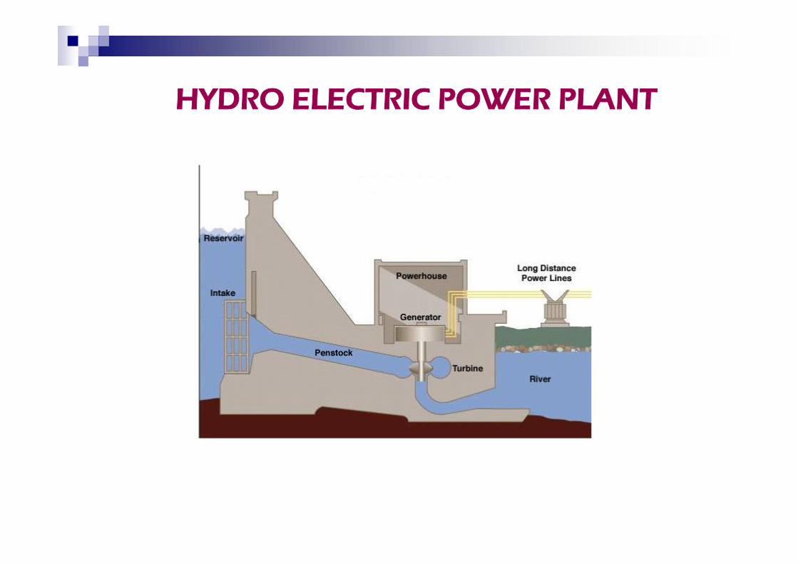
HYDRO ELECTRIC POWER PLANT
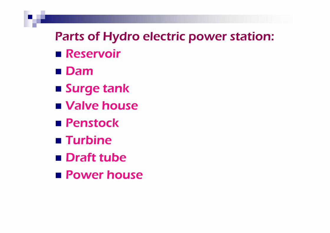
Parts of Hydro electric power station: Reservoir Dam Surge tank Valve house Penstock Turbine Draft tube Power house
Parts of Hydro electric power station: Reservoir Dam Surge tank Valve house Penstock Turbine Draft tube Power house
Advantages:
Water is the cheapest and reliable
source
No fuel transportation problem
Maintenance cost is low
Running cost is low
Life of this plant is more
Advantages:
Water is the cheapest and reliable
source
No fuel transportation problem
Maintenance cost is low
Running cost is low
Life of this plant is more
Disadvantages:
Long time for erection
Capital cost of the plant is high
Cost of transmission lines and
losses will be more
Depends on rain fall
Disadvantages:
Long time for erection
Capital cost of the plant is high
Cost of transmission lines and
losses will be more
Depends on rain fall
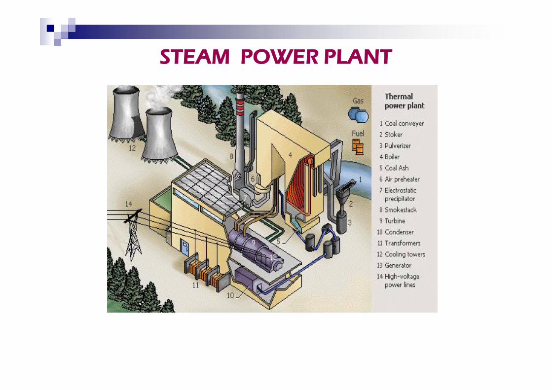
STEAM POWER PLANT
Advantages:
Fuel is the cheapest source
Capital cost is low
Cost of transmission lines and
losses will be low
Advantages:
Fuel is the cheapest source
Capital cost is low
Cost of transmission lines and
losses will be low
Disadvantages:
Maintenance cost of the plant is high
Running cost is high
Ash handling is difficult
Air is polluted
Disadvantages:
Maintenance cost of the plant is high
Running cost is high
Ash handling is difficult
Air is polluted
Nuclear Power plant
Energy released from the
continuous nuclear fission
Neutron from U-235 strikes
another nucleus and causes to
fission.
Energy released from the
continuous nuclear fission
Neutron from U-235 strikes
another nucleus and causes to
fission.
Main components: Fuel : pellets of
uranium - rods
Reactor core : no. of fuel rods
Moderator : to moderate the
neutron velocity
(graphite, heavy
and light water)
Fuel : pellets of
uranium - rods
Reactor core : no. of fuel rods
Moderator : to moderate the
neutron velocity
(graphite, heavy
and light water)
Coolant : to transfer heat
(water, liquid
metals)
Control rods : Neutron absorber
(cadmium, boron &
hafnium)
Pressure vessel : to maintain
constant pressure.
Coolant : to transfer heat
(water, liquid
metals)
Control rods : Neutron absorber
(cadmium, boron &
hafnium)
Pressure vessel : to maintain
constant pressure.
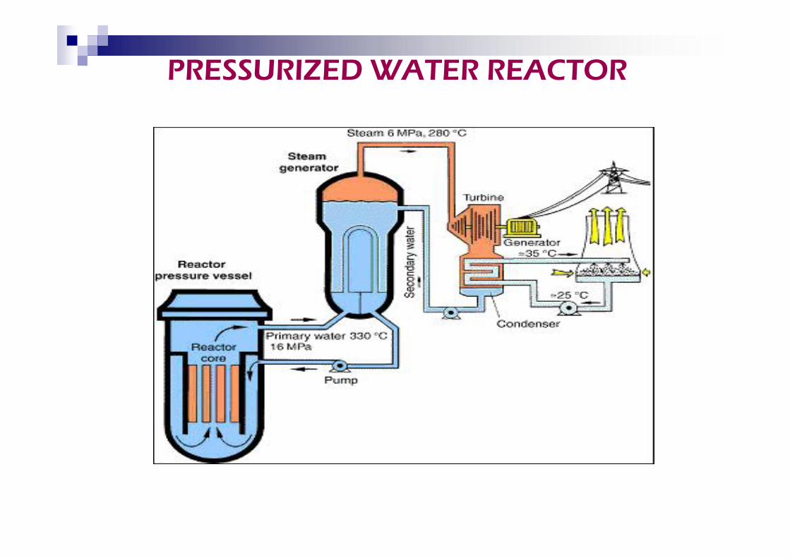
PRESSURIZED WATER REACTOR
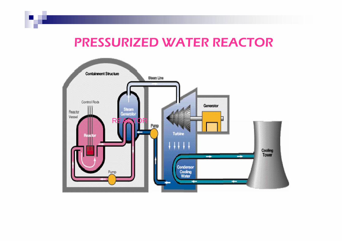
REACTOR
PRESSURIZED WATER REACTOR
REACTOR
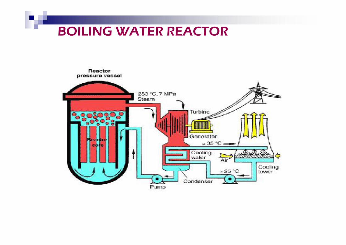
BOILING WATER REACTOR
Advantages:
Amount of fuel required is very
small
No fuel transportation problem
Less space is required
Located at load centre
Most economical
Advantages:
Amount of fuel required is very
small
No fuel transportation problem
Less space is required
Located at load centre
Most economical
Disadvantages:
Long time for erection
Capital cost and maintenance costof the plant are high
By products are radio active andcause pollution
Fuel is expensive
Disadvantages:
Long time for erection
Capital cost and maintenance costof the plant are high
By products are radio active andcause pollution
Fuel is expensive
TIDAL POWER PLANT
It is a rise and fall of water level of
sea
Due to the action of sun and moon
on the earth water.
It is a rise and fall of water level of
sea
Due to the action of sun and moon
on the earth water.
Classifications:
Single basin arrangement.
Double basin arrangement.
Classifications:
Single basin arrangement.
Double basin arrangement.
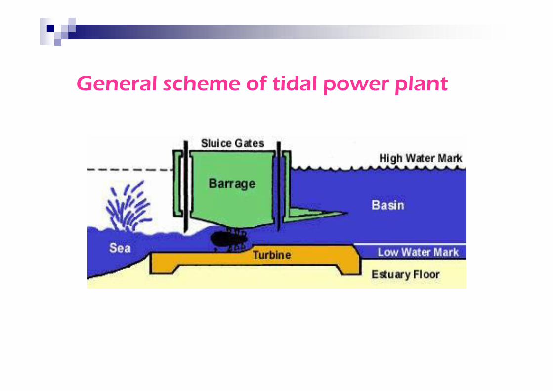
General scheme of tidal power plant
Main components:
a) Power house
b) Dam to form basin
c) Sluice gates
a) Power house
b) Dam to form basin
c) Sluice gates
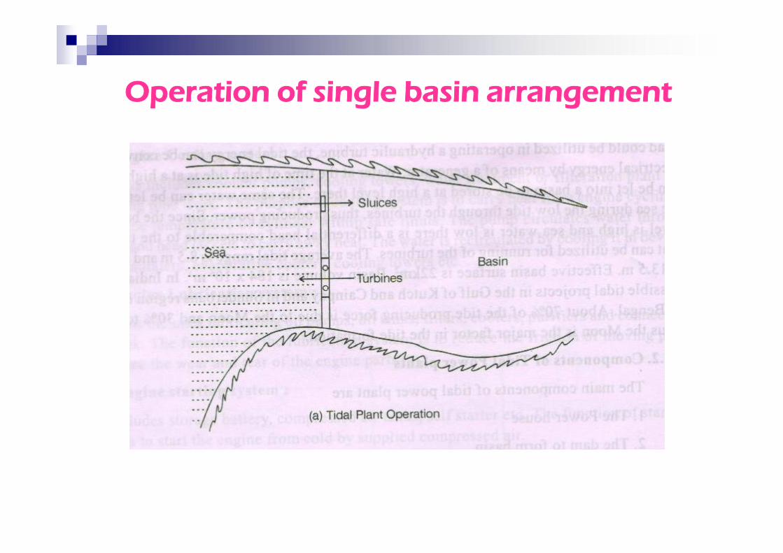
Operation of single basin arrangement
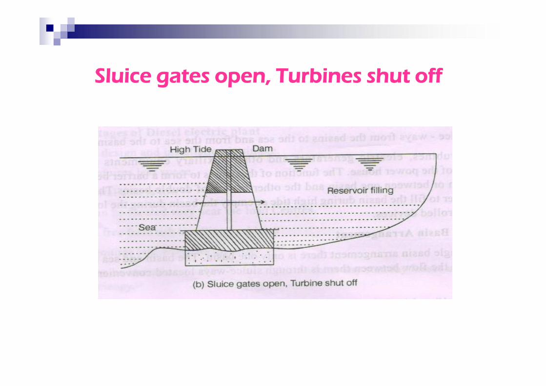
Sluice gates open, Turbines shut off
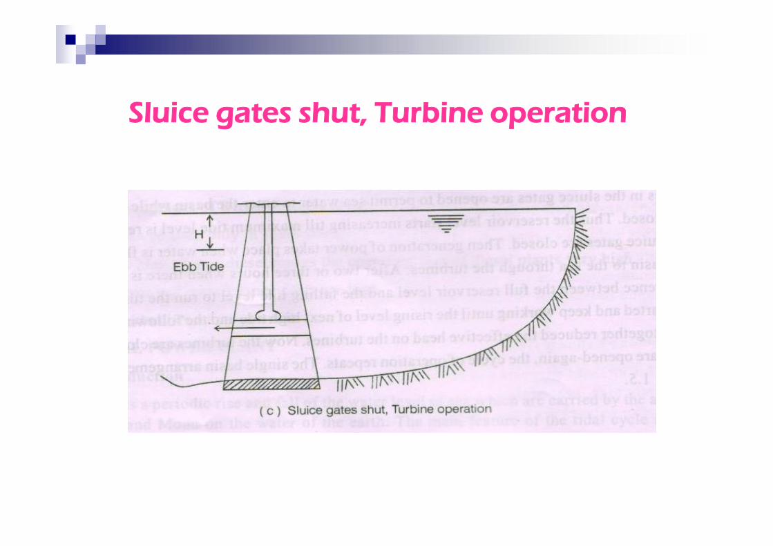
Sluice gates shut, Turbine operation
Advantages:
a) Renewable source of energy
b) Non polluting
c) No transportation problem
d) Cheaper
Advantages:
a) Renewable source of energy
b) Non polluting
c) No transportation problem
d) Cheaper
Disadvantages:
a) Tidal energy is fluctuating innature
b) Noisy in operation
c) Over all weight is very high
d) Not reliable
Disadvantages:
a) Tidal energy is fluctuating innature
b) Noisy in operation
c) Over all weight is very high
d) Not reliable
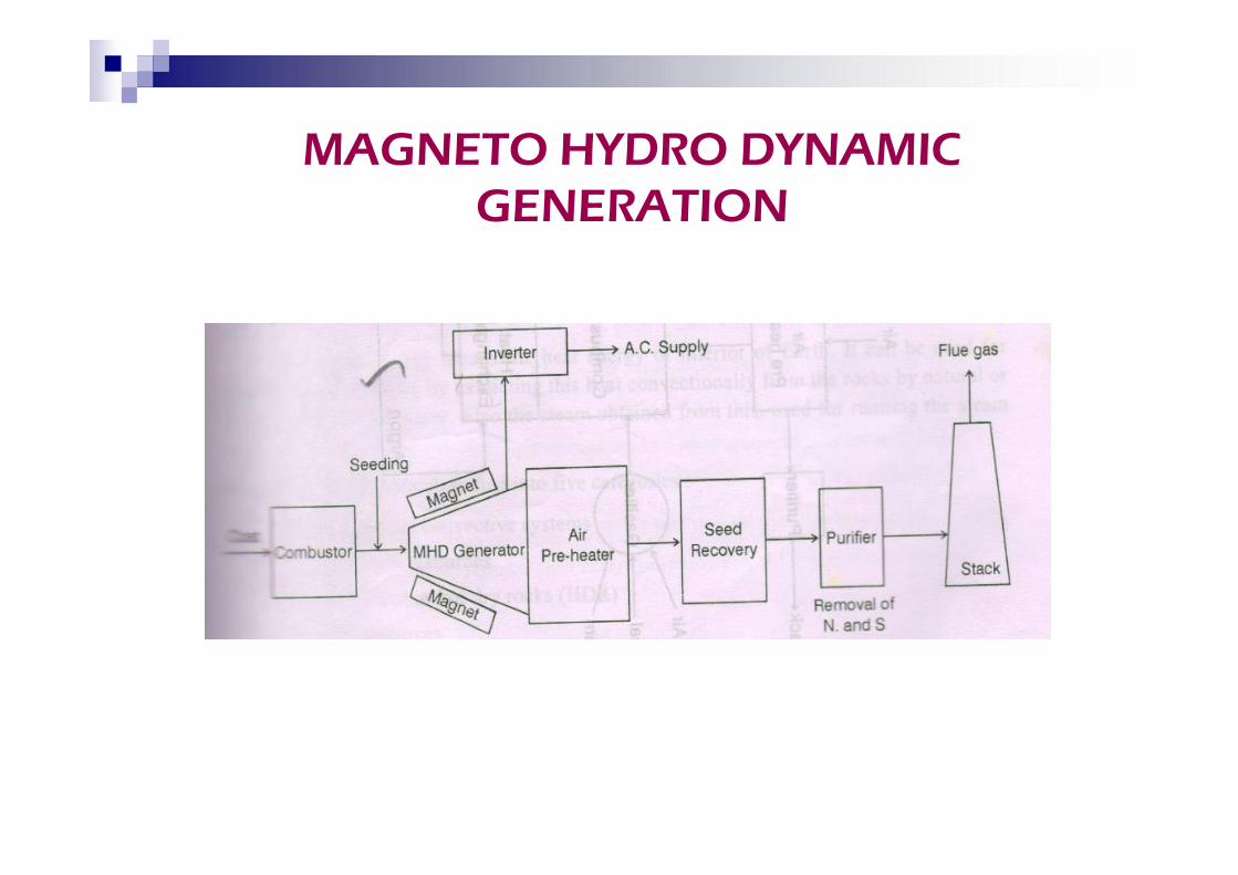
MAGNETO HYDRO DYNAMICGENERATION
Components:
a) Combustor
b) MHD generator
c) Air pre heater
Components:
a) Combustor
b) MHD generator
c) Air pre heater
a) Purifier
b) Inverter
c) Seed recovery
d) Stack
a) Purifier
b) Inverter
c) Seed recovery
d) Stack
ADVANTAGES
Conversion efficiency is around50%
Capital cost is less
Over all generation is less
No moving parts
Closed cycle system producespower, free of pollution
Conversion efficiency is around50%
Capital cost is less
Over all generation is less
No moving parts
Closed cycle system producespower, free of pollution
The heat energy of interior ofearth.
Classifications:
•Direct or dry steam PP
•Flash steam
•Binary fluid
GEOTHERMAL POWER PLANT The heat energy of interior of
earth.
Classifications:
•Direct or dry steam PP
•Flash steam
•Binary fluid
Components:
a) Hot brine
b) Turbine
c) Condenser
d) Heat exchanger
Components:
a) Hot brine
b) Turbine
c) Condenser
d) Heat exchanger
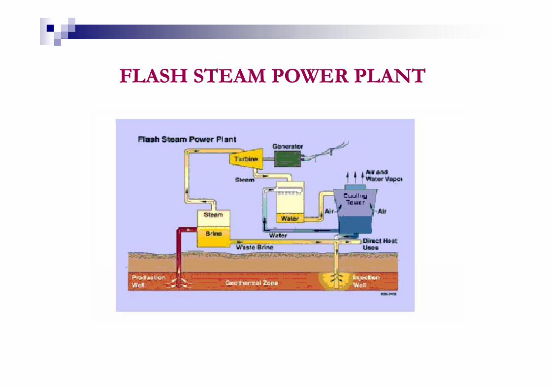
FLASH STEAM POWER PLANTFLASH STEAM POWER PLANT
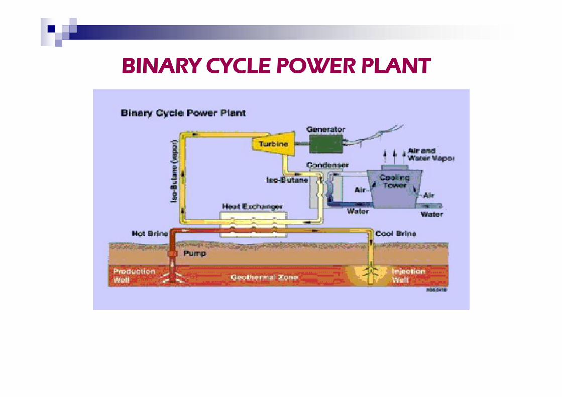
BINARY CYCLE POWER PLANTBINARY CYCLE POWER PLANT
Advantages:
Versatile in use
Cheaper
Highest annual load factor
Pollution less
Advantages:
Versatile in use
Cheaper
Highest annual load factor
Pollution less
Disadvantages:
Efficiency is low
Noisy drilling operation
Need large area
Disadvantages:
Efficiency is low
Noisy drilling operation
Need large area
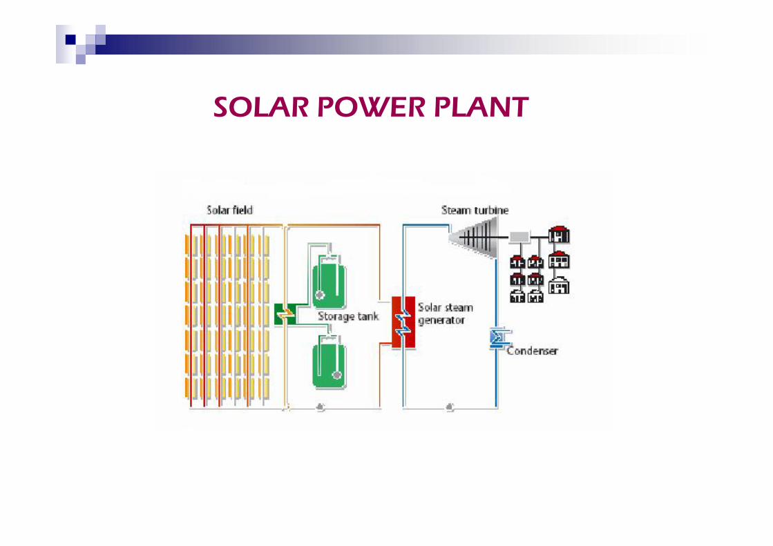
SOLAR POWER PLANT
Sub systems
Solar energy collection system
Thermal energy transfer system
Thermal energy storage system
Energy conversion system
Sub systems
Solar energy collection system
Thermal energy transfer system
Thermal energy storage system
Energy conversion system
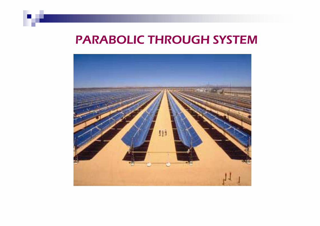
PARABOLIC THROUGH SYSTEM
Advantages:
It is free of pollution
Requires little maintenance
economical
Advantages:
It is free of pollution
Requires little maintenance
economical
Disadvantages:
Available only by day not whensun is cloudy
Not reliable
Located at high attitudes
Initial cost is high.
Disadvantages:
Available only by day not whensun is cloudy
Not reliable
Located at high attitudes
Initial cost is high.

DISTRIBUTED GENERATION
The integrated use of small generation
units directly connected to the system
They operate on a renewable fuel such
as sun light, wind, gas and biomass
The integrated use of small generation
units directly connected to the system
They operate on a renewable fuel such
as sun light, wind, gas and biomass
Example of technologies used :
Micro turbines
Fuel cells
Photovoltaic cell
Internal combustion engines
Example of technologies used :
Micro turbines
Fuel cells
Photovoltaic cell
Internal combustion engines

UNIT II
CONSERVATIONCONSERVATION
Economics of Generation
Connected load - sum of continuousratings of allsystems
Maximum demand - greatest demand ofload
Demand factor - Maximum demandConnected load
Connected load - sum of continuousratings of allsystems
Maximum demand - greatest demand ofload
Demand factor - Maximum demandConnected load
Load factor - Average load/Maximumdemand
Diversity factor - Sum of individualDemand / Max.demand
Capacity factor - Average demand/ plantcapacity
Load factor - Average load/Maximumdemand
Diversity factor - Sum of individualDemand / Max.demand
Capacity factor - Average demand/ plantcapacity
Load curve
Curve showing the load demand Very useful in determining the annual
requirements for energy
Curve showing the load demand Very useful in determining the annual
requirements for energy
Load duration curve
Obtained from load curveLoad elements of load curve are arranged
in descending order
Obtained from load curveLoad elements of load curve are arranged
in descending order
Load on the power station:
Base load - unvarying load occursthe whole day.
Peak load - various peak demandsof load over & abovebase load
Base load - unvarying load occursthe whole day.
Peak load - various peak demandsof load over & abovebase load
Cost of Electrical Energy
Fixed cost
Running cost (or ) cost of energy
Fixed cost
Running cost (or ) cost of energy
Fixed cost:
Cost which is independent of
maximum demand &units generated
Capital cost of power plant
Interest on capital, taxes &insurance
Fixed cost:
Cost which is independent of
maximum demand &units generated
Capital cost of power plant
Interest on capital, taxes &insurance
Running cost :
Depends on only upon the no of
units generated
Cost of fuel
Maintenance cost
Operation cost.
Depends on only upon the no of
units generated
Cost of fuel
Maintenance cost
Operation cost.
Tariff
Different methods of charging
consumers are known as tariff
It should be simple and
comprehensible to the public
It should be uniform
Different methods of charging
consumers are known as tariff
It should be simple and
comprehensible to the public
It should be uniform
Types of tariff:
Simple tariff
Flat rate tariff
Block rate tariff
Two part tariff
Maximum demand tariff
Power factor tariff
Simple tariff
Flat rate tariff
Block rate tariff
Two part tariff
Maximum demand tariff
Power factor tariff
Need for Electrical Energy Conservation
• In order to save the scarce and fastdepleting non renewable energy, sourcessuch as coal, gas etc.
• To protect the environment from thepollution caused by them
• In order to save the scarce and fastdepleting non renewable energy, sourcessuch as coal, gas etc.
• To protect the environment from thepollution caused by them
Effect on Energy Conservation
The energy conservation results in Optimal utilization energy
Prolong the usage of energyavailable in the earth
Reduce green house gas emission
Minimize the global warming
The energy conservation results in Optimal utilization energy
Prolong the usage of energyavailable in the earth
Reduce green house gas emission
Minimize the global warming
Energy Management
The judicious and effective use of energycost to minimize energy cost & tomaximize profits.
Reduce avoidable losses
Use energy efficient technologies
The judicious and effective use of energycost to minimize energy cost & tomaximize profits.
Reduce avoidable losses
Use energy efficient technologies
Energy management strategy
Appoint Energy Manager Conduct Energy Audit Formalize an Energy Management Policy
Statement Conduct Staff Awareness & Training
Programme Annual report
Appoint Energy Manager Conduct Energy Audit Formalize an Energy Management Policy
Statement Conduct Staff Awareness & Training
Programme Annual report
Energy Auditing
Key to a systematic approach for decisionmaking area of energy management.
Quantifies energy usage according to itsdiscrete function
Verification, Monitoring & Analysis of useof energy including submission oftechnical report
Key to a systematic approach for decisionmaking area of energy management.
Quantifies energy usage according to itsdiscrete function
Verification, Monitoring & Analysis of useof energy including submission oftechnical report
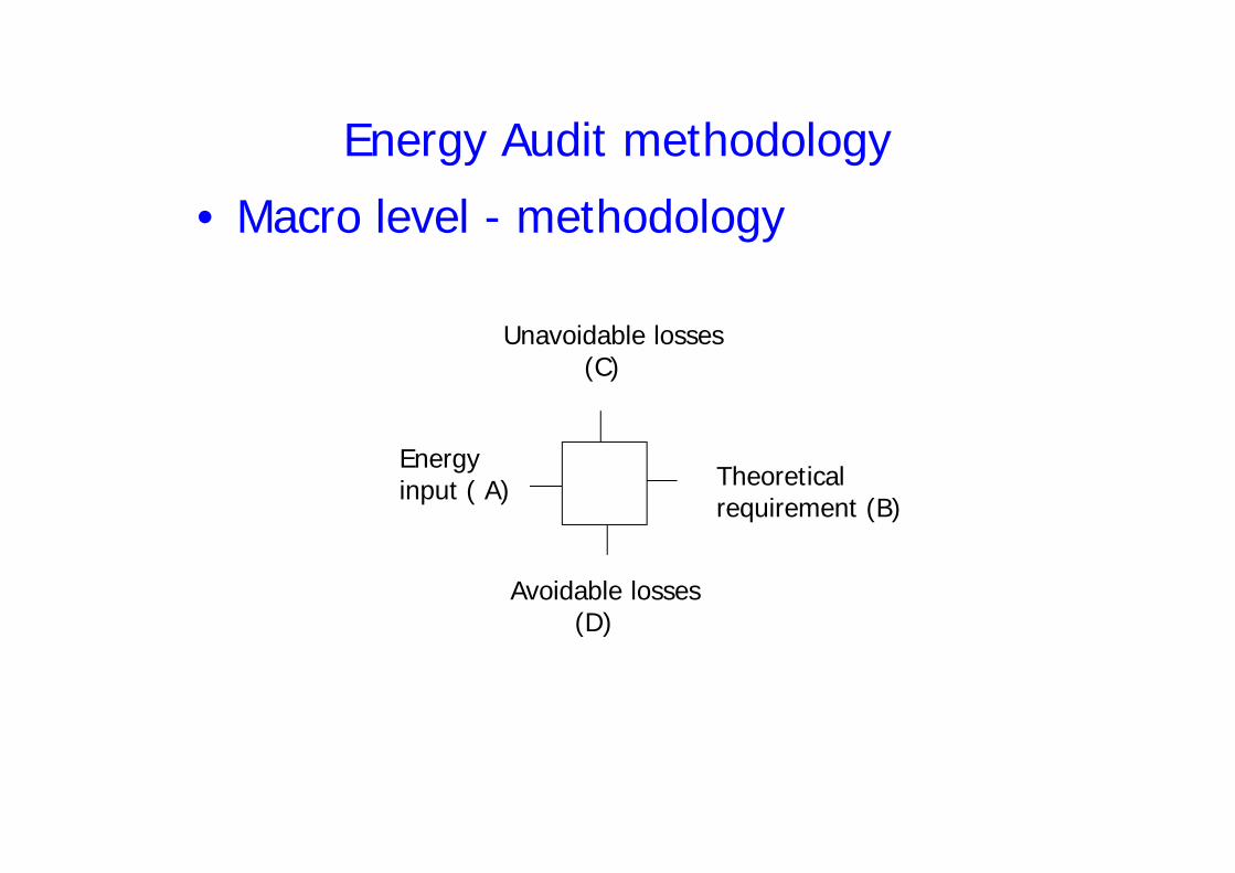
Energy Audit methodology
• Macro level - methodology
Energyinput ( A)
Unavoidable losses(C)
Energyinput ( A)
Avoidable losses(D)
Theoreticalrequirement (B)
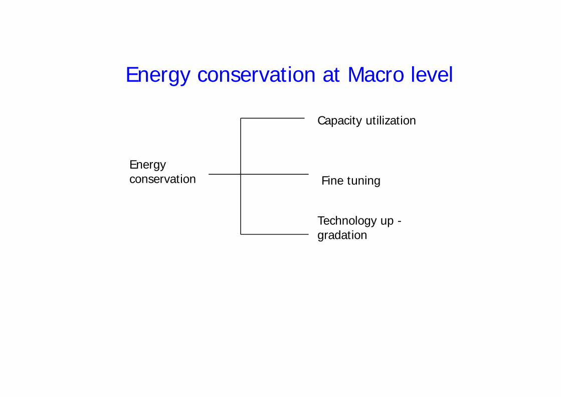
Energyconservation
Capacity utilization
Fine tuning
Energy conservation at Macro level
Technology up -gradation
Types of Energy Audit:
Preliminary Energy Audit
Detailed Energy Audit
Types of Energy Audit:
Preliminary Energy Audit
Detailed Energy Audit
Preliminary Energy Audit
To establish energy consumption
To estimate the scope for energy
savings
Identify simple energy saving
proposals
To establish energy consumption
To estimate the scope for energy
savings
Identify simple energy saving
proposals
Detailed Energy Audit
Pre Audit phase
Detailed Audit phase
Post Audit phase
Pre Audit phase
Detailed Audit phase
Post Audit phase
Economics of power factor improvement
The power factor can be improved by
Installing static power capacitors
Operating synchronous motor in over
excited
Installing static VAR compensators
The power factor can be improved by
Installing static power capacitors
Operating synchronous motor in over
excited
Installing static VAR compensators
Method of Power factor improvement
Centralized / group compensation
Distributed / Individual
compensation
Mixed compensation
Centralized / group compensation
Distributed / Individual
compensation
Mixed compensation
POWER QUALITY
It means that supply of powerwithin the permitted variation ofvoltage and frequency and withoutdistortion of sinusoidal wave form inbalance condition
It means that supply of powerwithin the permitted variation ofvoltage and frequency and withoutdistortion of sinusoidal wave form inbalance condition
Parameters
Voltage
Frequency
Harmonics
Power supply disturbances (sags,swells, transients, flickers, interruptsoutages etc.)
Voltage
Frequency
Harmonics
Power supply disturbances (sags,swells, transients, flickers, interruptsoutages etc.)
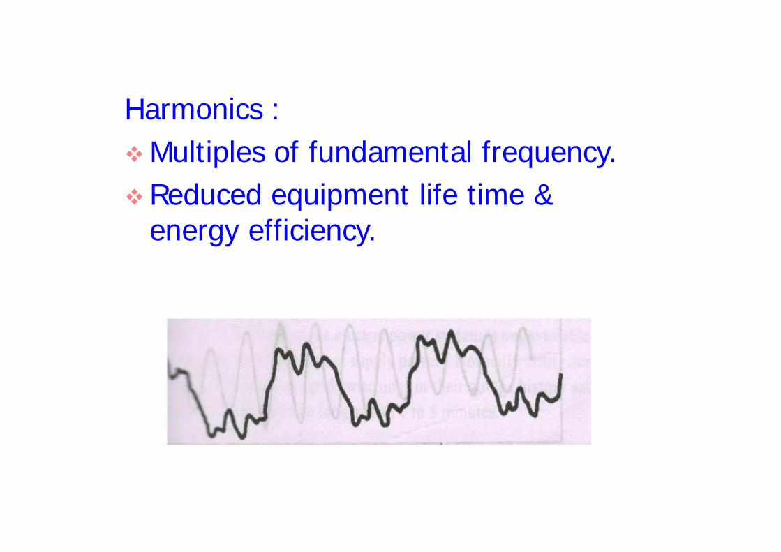
Harmonics :Multiples of fundamental frequency.Reduced equipment life time &
energy efficiency.
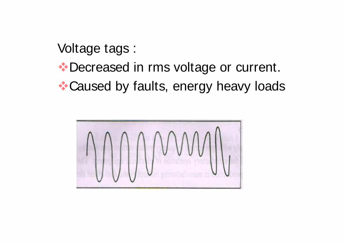
Voltage tags :Decreased in rms voltage or current.Caused by faults, energy heavy loads
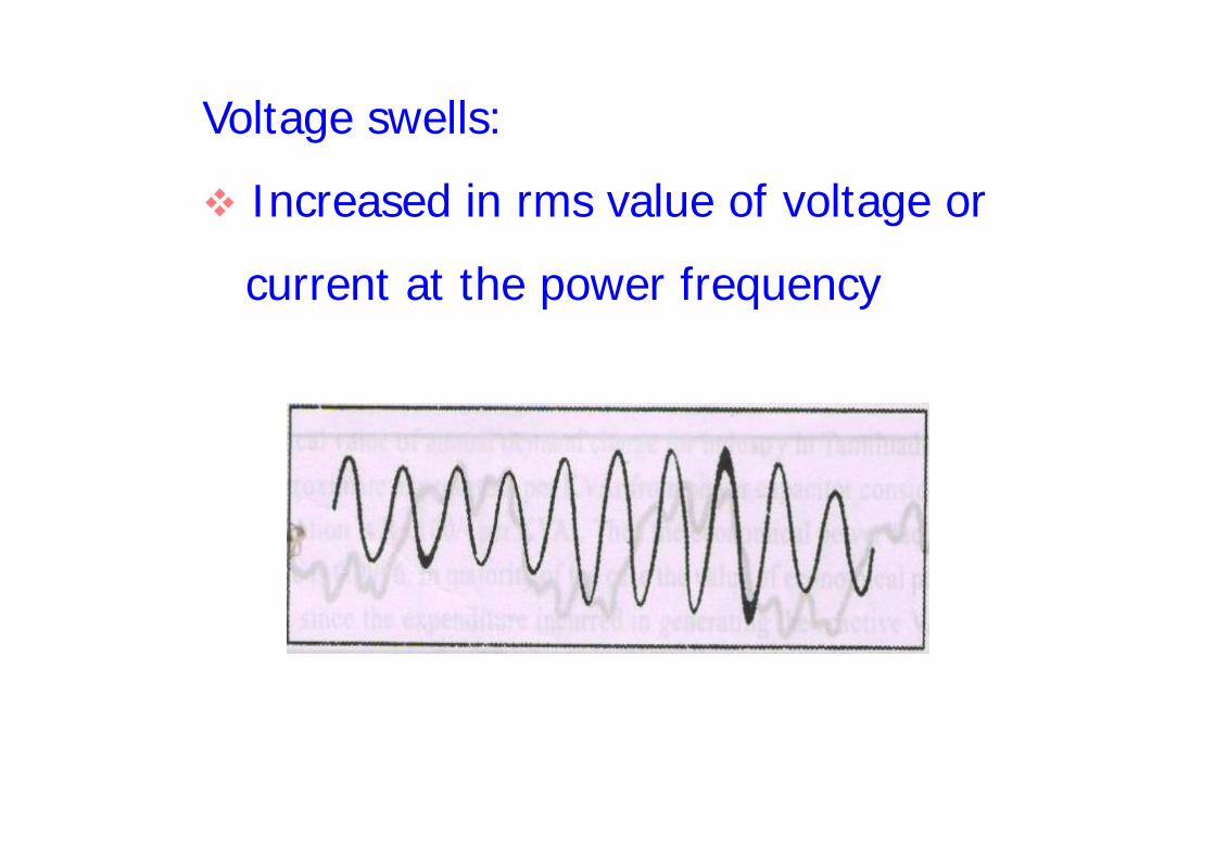
Voltage swells:
Increased in rms value of voltage or
current at the power frequency
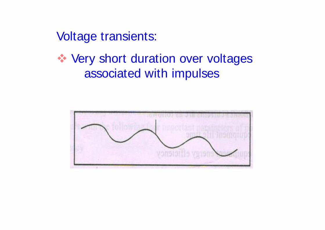
Voltage transients:
Very short duration over voltagesassociated with impulses
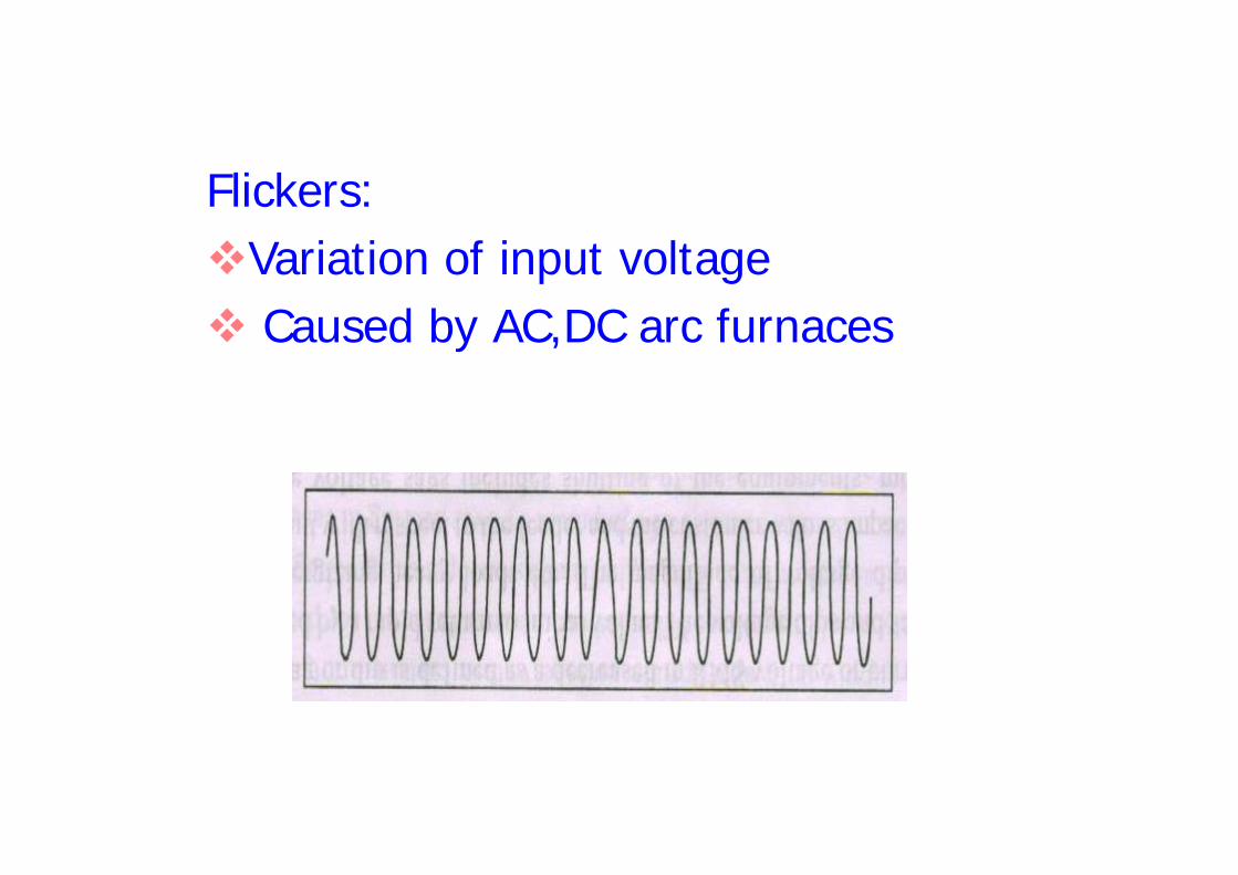
Flickers:Variation of input voltage Caused by AC,DC arc furnaces

UNIT III
ILLUMINATION, HEATINGAND WELDING
ILLUMINATION, HEATINGAND WELDING

ILLUMINATION

Definition of terms
Illumination : Result of lightingfalling on surface.
Luminous Intensity : light output fallingon unit squaremeter of surface,unit is lux
Reflection Factor : Ratio betweenreflected light to theincident light
Illumination : Result of lightingfalling on surface.
Luminous Intensity : light output fallingon unit squaremeter of surface,unit is lux
Reflection Factor : Ratio betweenreflected light to theincident light

MHSP : Mean Spherical CandlePower- total flux / 4 π
MHCP : Mean Horizontal CandlePower
Reduction factor : MSCP / MHCP
MHSP : Mean Spherical CandlePower- total flux / 4 π
MHCP : Mean Horizontal CandlePower
Reduction factor : MSCP / MHCP
Laws of Illumination
Inverse Square law
Lambert’s Cosine law
Inverse Square law
Lambert’s Cosine law
Measurement of Luminous intensity
Bunsen photometer head
Lummer – Brodhun photometer head
Flicker photometer head
Bunsen photometer head
Lummer – Brodhun photometer head
Flicker photometer head
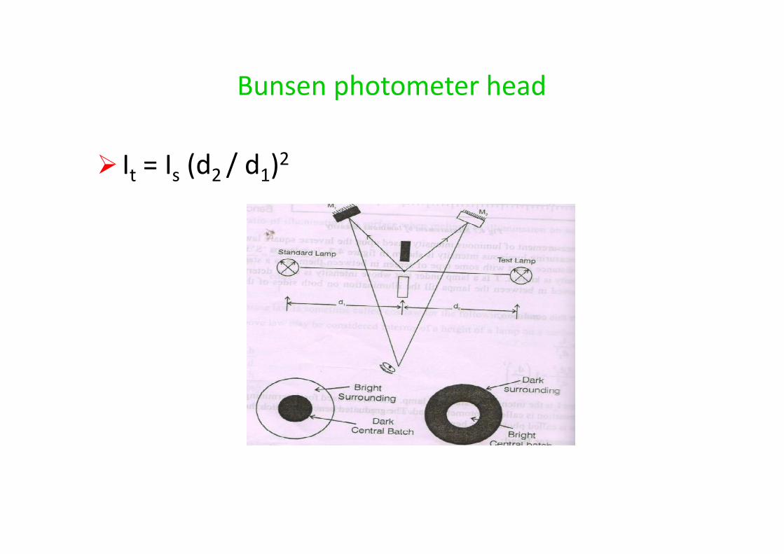
Bunsen photometer head
It = Is (d2 / d1)2
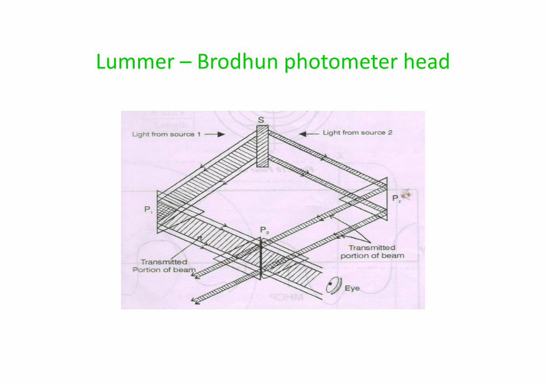
Lummer – Brodhun photometer head
Types of Lamp
Filament Lamp (GLS)
Tungsten Halogen Lamp
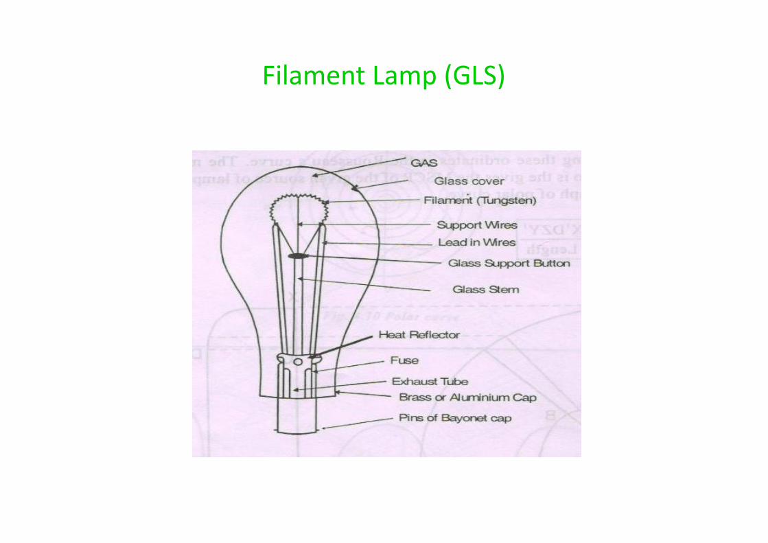
Filament Lamp (GLS)
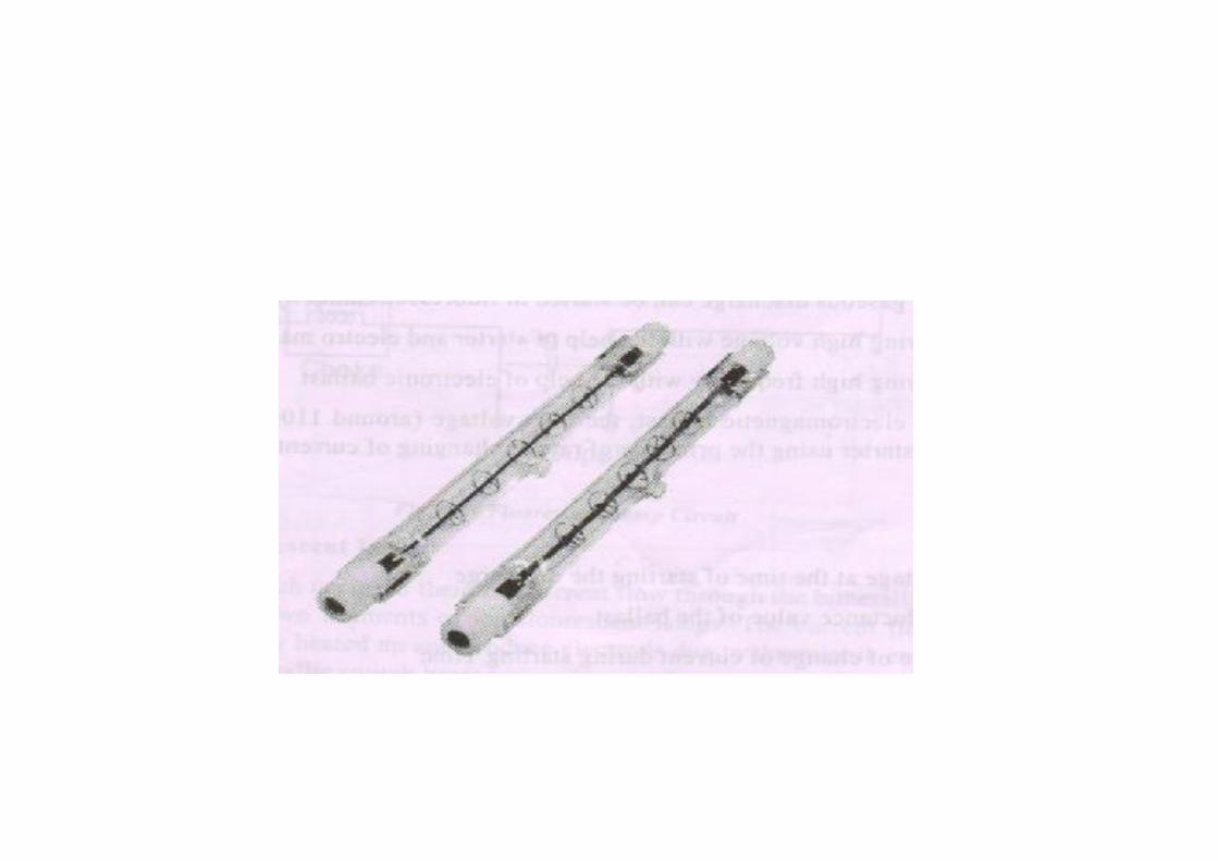
Tungsten Halogen Lamp
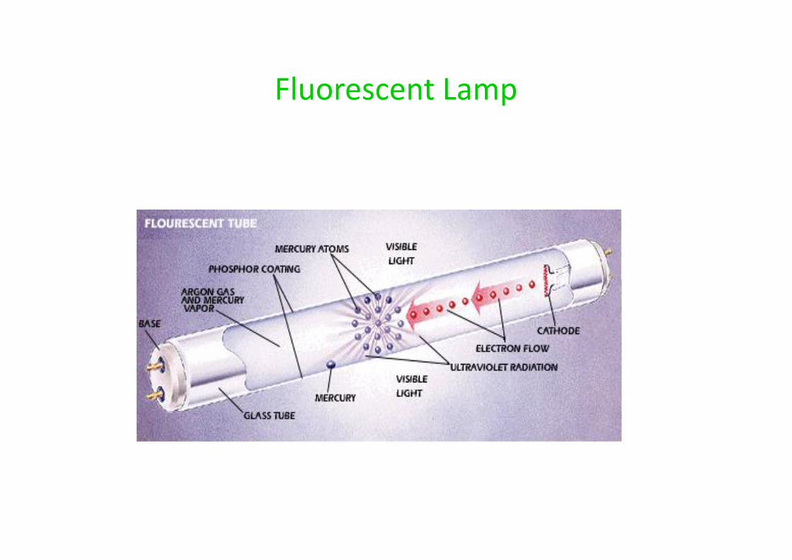
Fluorescent Lamp

High Pressure Mercury Vapour Lamp
Types of Lighting
Direct lighting
semi direct
Indirect
Semi indirect
Direct lighting
semi direct
Indirect
Semi indirect

HEATING
When electric current passes through amedium, heat is produced
H = I2 Rt Joules
Properties of heating materials
High specific resistance
High melting point
Freedom from oxidation
Small temperature coefficient
High specific resistance
High melting point
Freedom from oxidation
Small temperature coefficient
Types of Heating
Resistance heatinga) Directb) Indirect
Induction heatinga) Direct
b) Indirect Dielectric heating Arc heating
Resistance heatinga) Directb) Indirect
Induction heatinga) Direct
b) Indirect Dielectric heating Arc heating
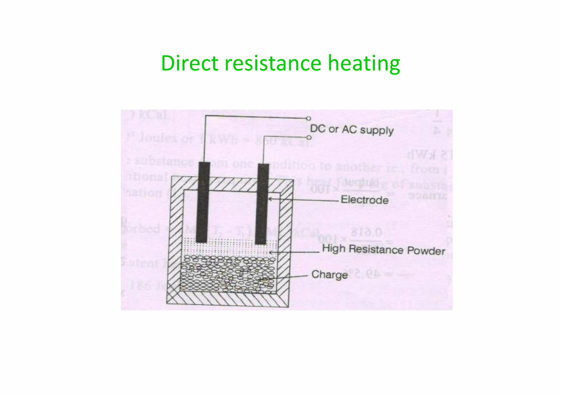
Direct resistance heating
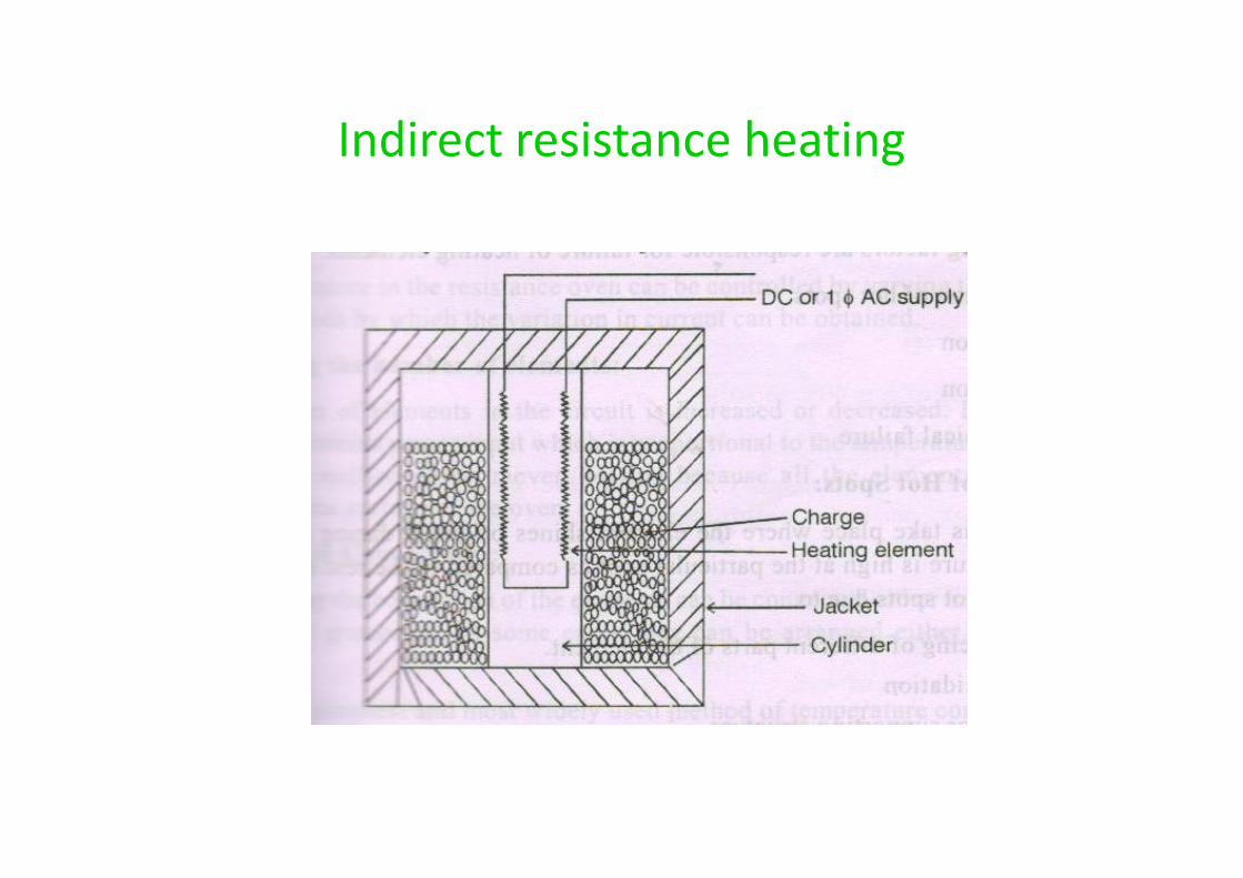
Indirect resistance heating
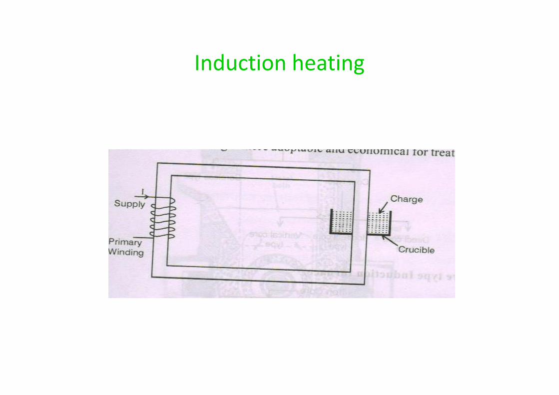
Induction heating
Types of Induction furnaces
Core typea) Directb) Indirectc) Vertical
Coreless type
Core typea) Directb) Indirectc) Vertical
Coreless type
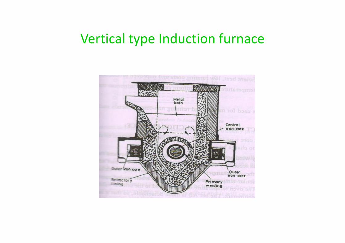
Vertical type Induction furnace
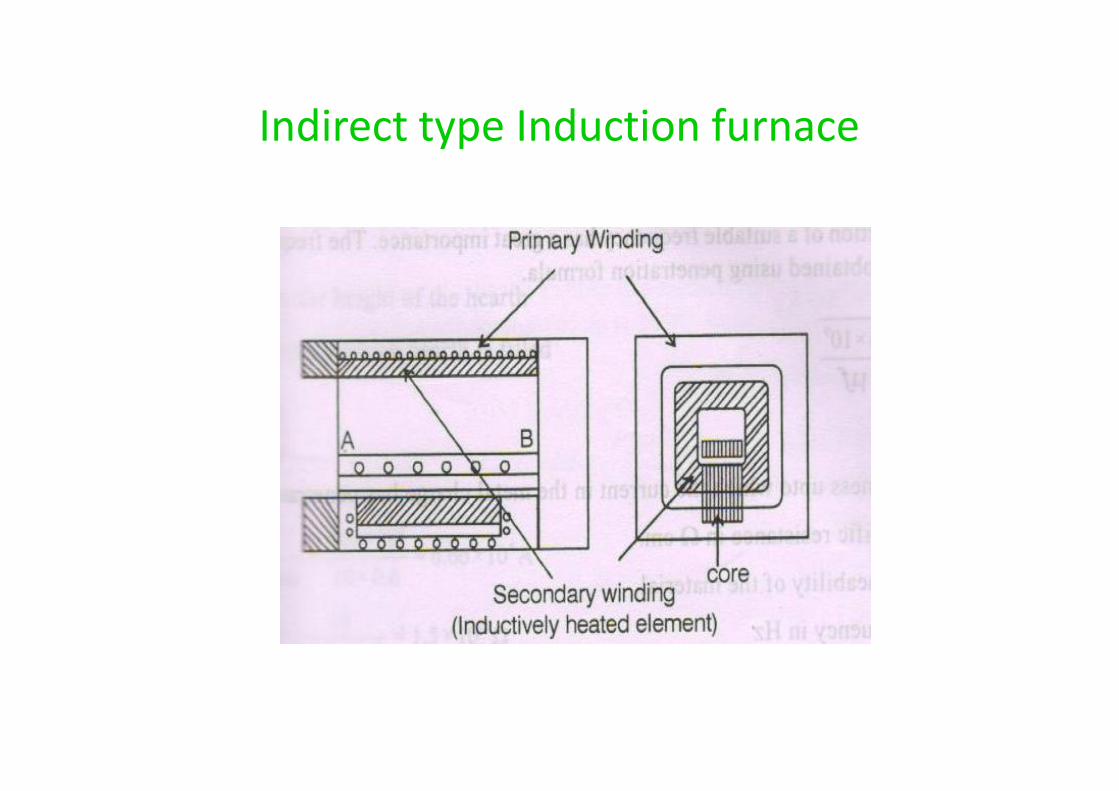
Indirect type Induction furnace
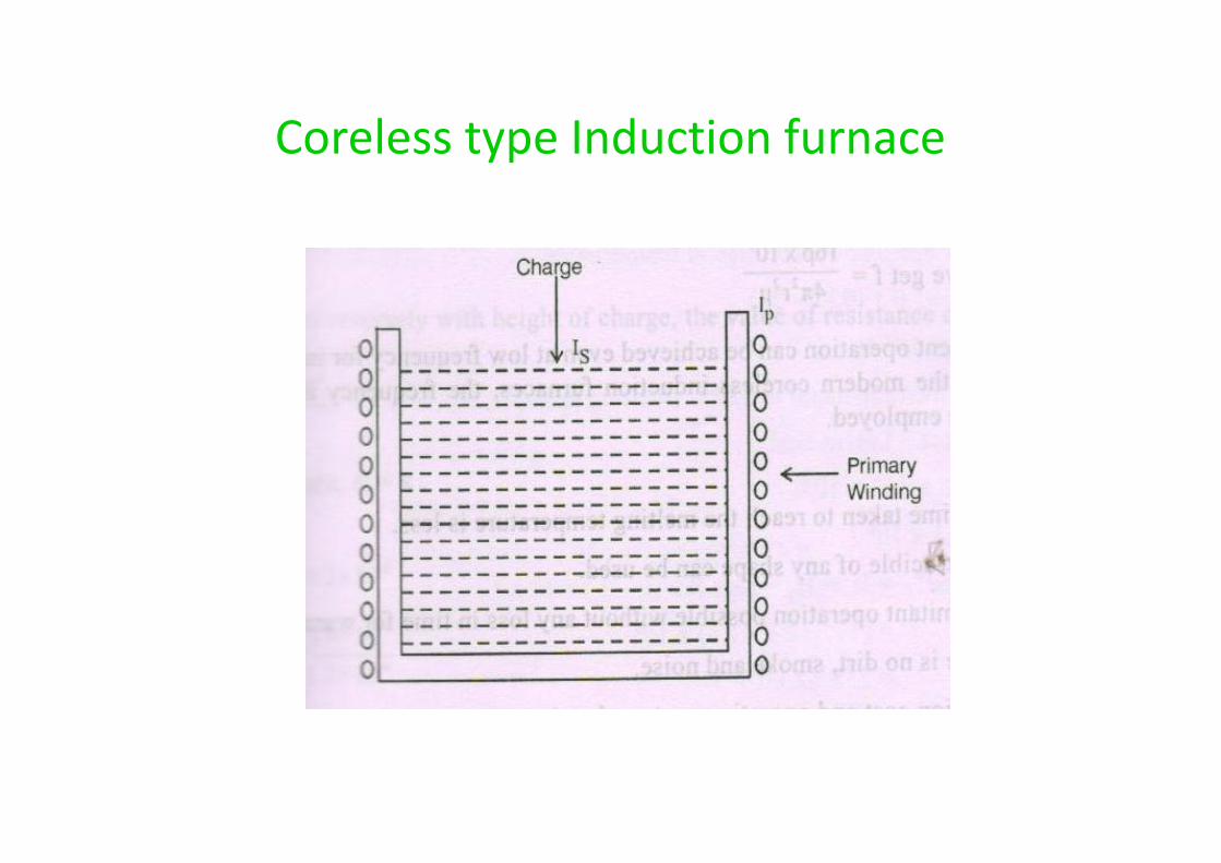
Coreless type Induction furnace
UNIT V
ELECTRIC TRACTION
INTRODUCTION
• Locomotion in which driving force is obtainedfrom motors
• Driving equipment should be capable ofoverloads for short periods
• Maximum tractive effort should be exerted atstarting
• Wear should be minimum
• Locomotion in which driving force is obtainedfrom motors
• Driving equipment should be capable ofoverloads for short periods
• Maximum tractive effort should be exerted atstarting
• Wear should be minimum
Advantages :
• Cheapest method• Free from smoke and flue gas• Very high starting torque• Smooth and rapid acceleration and braking• Adhesion coefficient is better• Great passenger carrying capacity
• Cheapest method• Free from smoke and flue gas• Very high starting torque• Smooth and rapid acceleration and braking• Adhesion coefficient is better• Great passenger carrying capacity
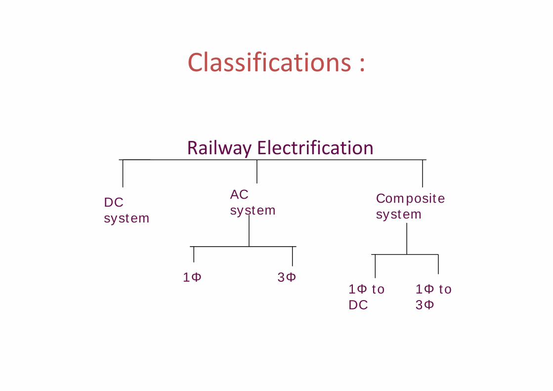
Classifications :
Railway Electrification
DCsystem
ACsystem
Compositesystem
DCsystem
ACsystem
Compositesystem
1Φ 3Φ1Φ toDC
1Φ to3Φ
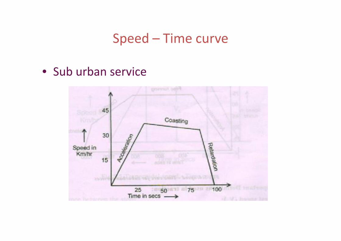
Speed – Time curve
• Sub urban service
It consists of
Acceleration period Free run period Coasting period Braking period
It consists of
Acceleration period Free run period Coasting period Braking period
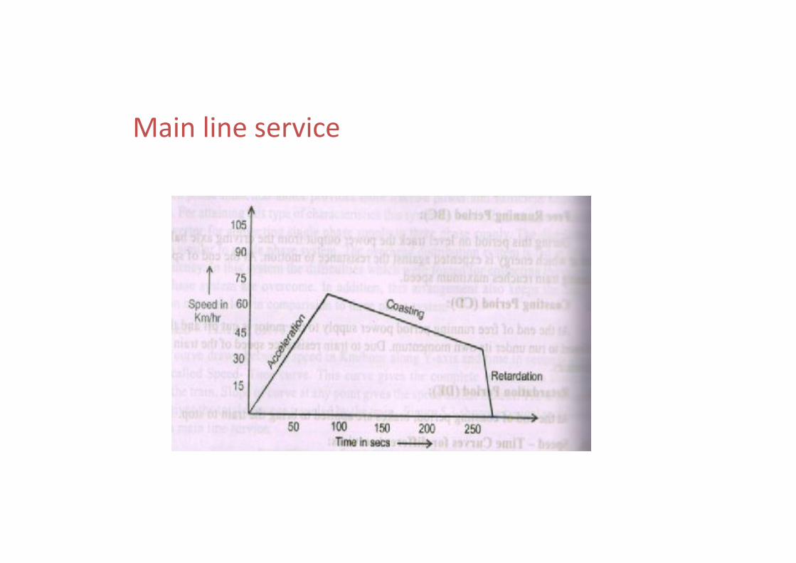
Main line service
Important terms
• Creset speed (Vc)
- maximum speed attained bytrain during run
Average speed (Va)
- Distance between stops in km
Actual time of run in hour
• Creset speed (Vc)
- maximum speed attained bytrain during run
Average speed (Va)
- Distance between stops in km
Actual time of run in hour
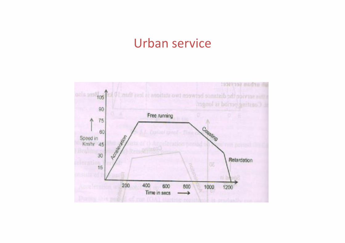
Urban service
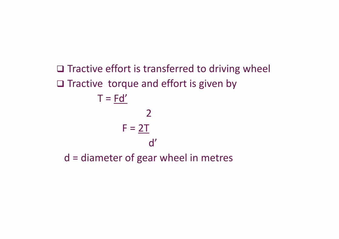
Tractive effort is transferred to driving wheel Tractive torque and effort is given by
T = Fd’2
F = 2Td’
d = diameter of gear wheel in metres
Tractive effort is transferred to driving wheel Tractive torque and effort is given by
T = Fd’2
F = 2Td’
d = diameter of gear wheel in metres
Tractive effort for propulsion of a train
• component needed to provide acceleration
• component needed to overcome trainresistance
• component needed to overcome gradients
• component needed to provide acceleration
• component needed to overcome trainresistance
• component needed to overcome gradients
Factors affecting specific energy consumption
• Distance between the stops
• Maximum speed
• Weight of the train
• Train resistance
• Acceleration and retardation
• Distance between the stops
• Maximum speed
• Weight of the train
• Train resistance
• Acceleration and retardation
Teaction motor control
• DC series motor control
• Series – parallel control of DC seriesmotor
• DC series motor control
• Series – parallel control of DC seriesmotor
DC series motor control
• At the time of starting, no back emf, so motorspeed is high.
• to limit the current, starting resistance isadded.
• Some energy is wasted in resistance
• At the time of starting, no back emf, so motorspeed is high.
• to limit the current, starting resistance isadded.
• Some energy is wasted in resistance
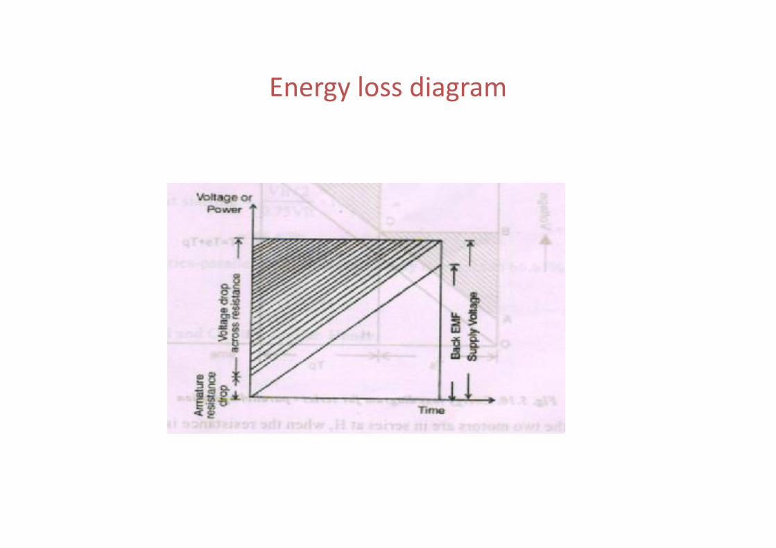
Energy loss diagram
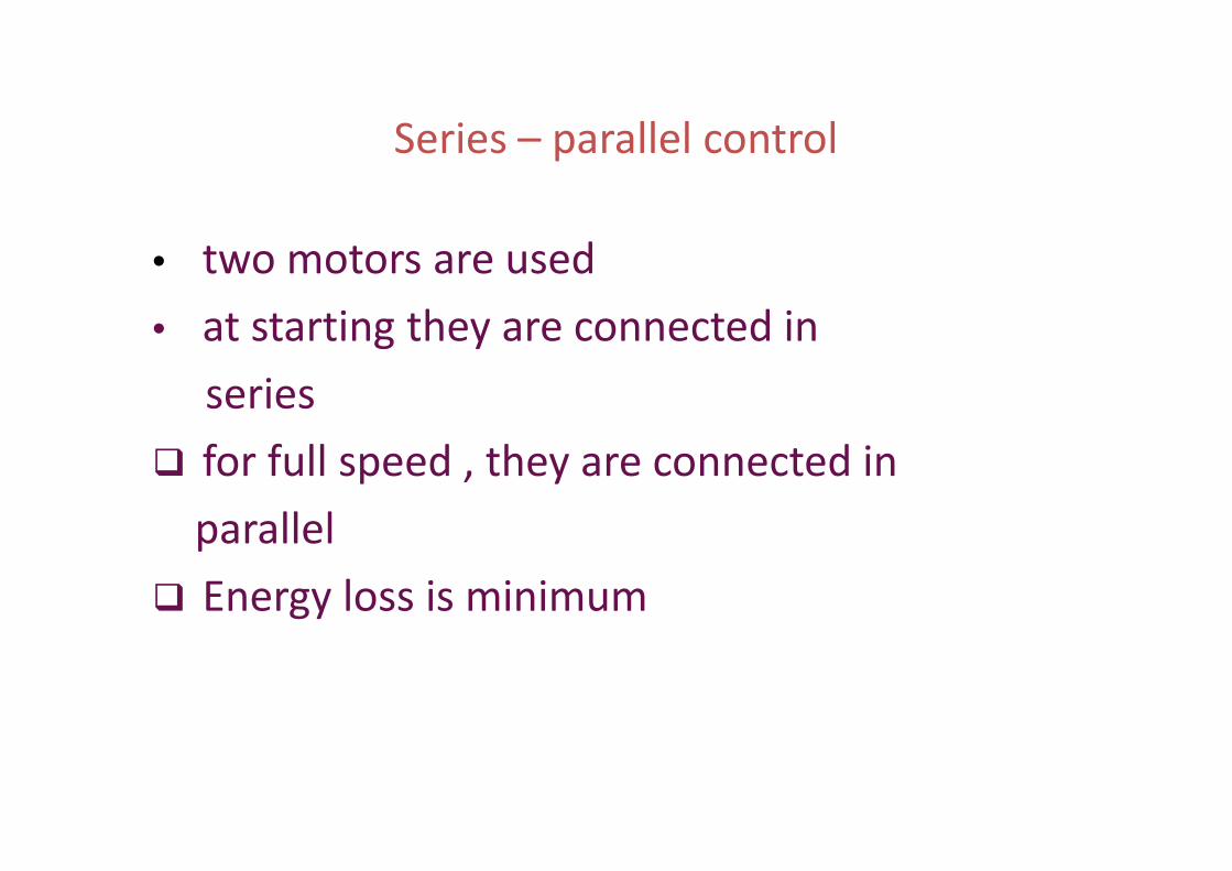
Series – parallel control
• two motors are used• at starting they are connected in
series for full speed , they are connected in
parallel Energy loss is minimum
• two motors are used• at starting they are connected in
series for full speed , they are connected in
parallel Energy loss is minimum
Energy loss diagram
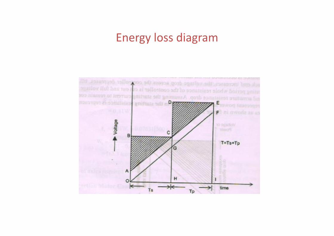
Series – parallel starting methods
• Shunt or short circuit transition method
• Bridge transition method
• Shunt or short circuit transition method
• Bridge transition method
Shunt transition methods
Full series first transitionSecond transitionThird transitionFirst parallel full parallel
Full series first transitionSecond transitionThird transitionFirst parallel full parallel
first seriesFull seriesTransition first parallel full parallel
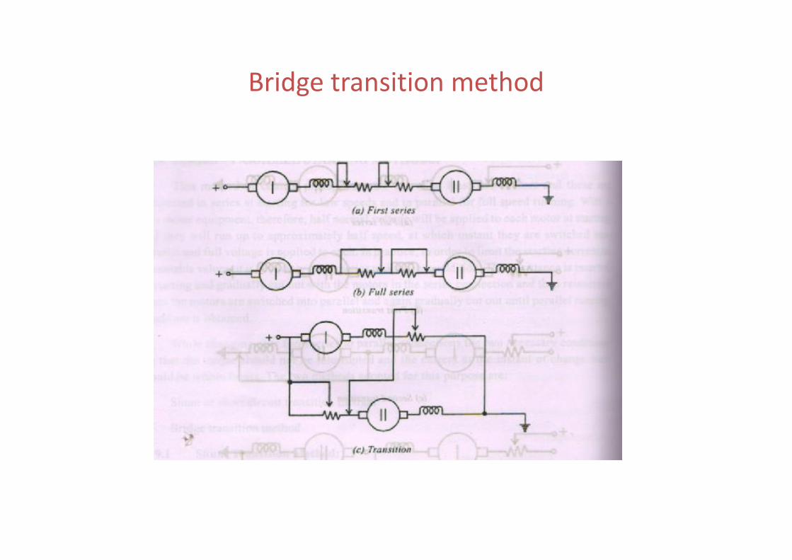
Bridge transition method
first seriesFull seriesTransition first parallel full parallel
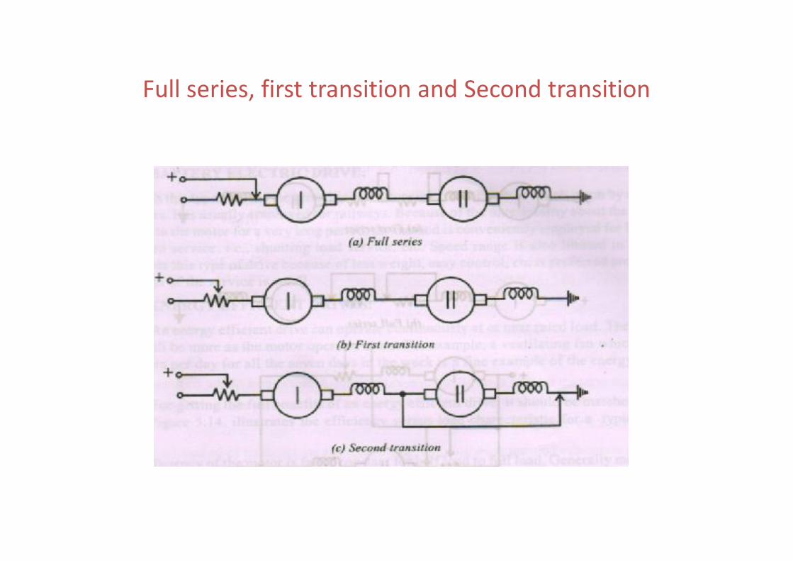
Full series, first transition and Second transition
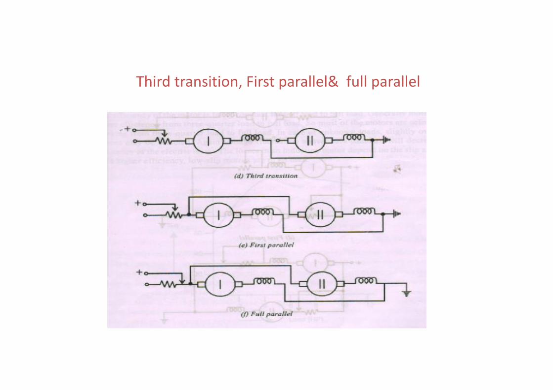
Third transition, First parallel& full parallel
Bridge transition method
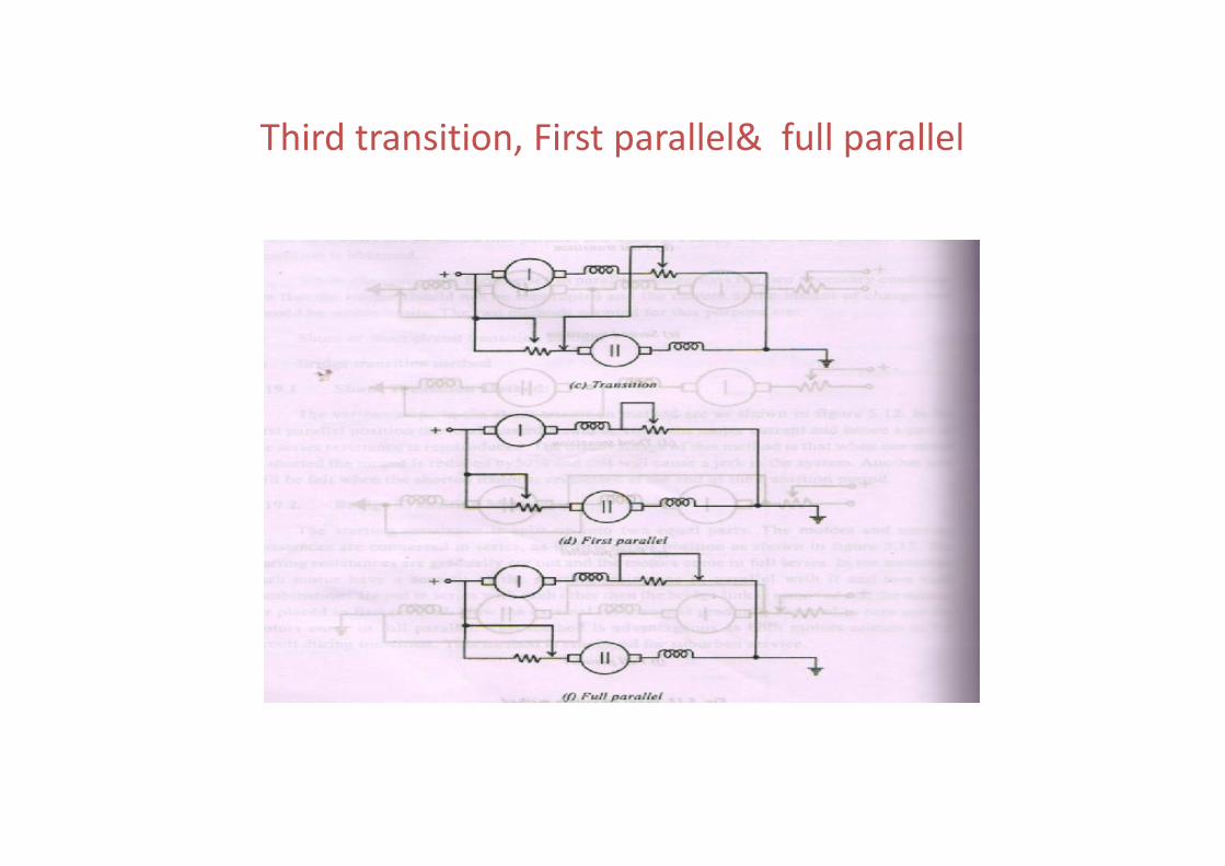
Third transition, First parallel& full parallel
Recent trends in electric traction
PWM technique is applied PWM AC drives used in subways, rail cars, trolley
buses, diesel electric and electric locomotives. GTOs are user in PWM inverter technologyMicroprocessors unit controls firing pulses to the
GTOs
PWM technique is applied PWM AC drives used in subways, rail cars, trolley
buses, diesel electric and electric locomotives. GTOs are user in PWM inverter technologyMicroprocessors unit controls firing pulses to the
GTOs
Advanced speed control
Tap changer control
Thyristor control
Chopper control
Microprocessor control
Tap changer control
Thyristor control
Chopper control
Microprocessor control
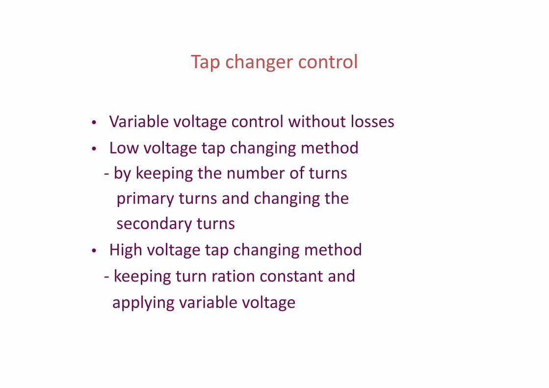
Tap changer control
• Variable voltage control without losses• Low voltage tap changing method
- by keeping the number of turnsprimary turns and changing thesecondary turns
• High voltage tap changing method- keeping turn ration constant and
applying variable voltage
• Variable voltage control without losses• Low voltage tap changing method
- by keeping the number of turnsprimary turns and changing thesecondary turns
• High voltage tap changing method- keeping turn ration constant and
applying variable voltage
Thyristor control
Magnitude of DC voltage is decided byaverage of the positive half cycles allowed topass through the rectifiers
by allowing positive half cycles
by not allowing certain portion of positive halfcycles
Magnitude of DC voltage is decided byaverage of the positive half cycles allowed topass through the rectifiers
by allowing positive half cycles
by not allowing certain portion of positive halfcycles
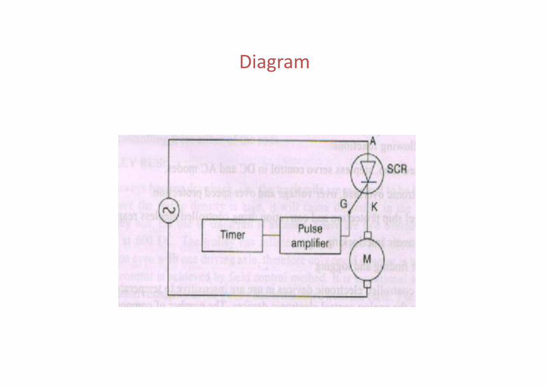
Diagram
Chopper control
• Pulse Width Modulation- time period constant with variation in Ton & Toff
• Pulse Width Modulation- time period constant with variation in Ton & Toff
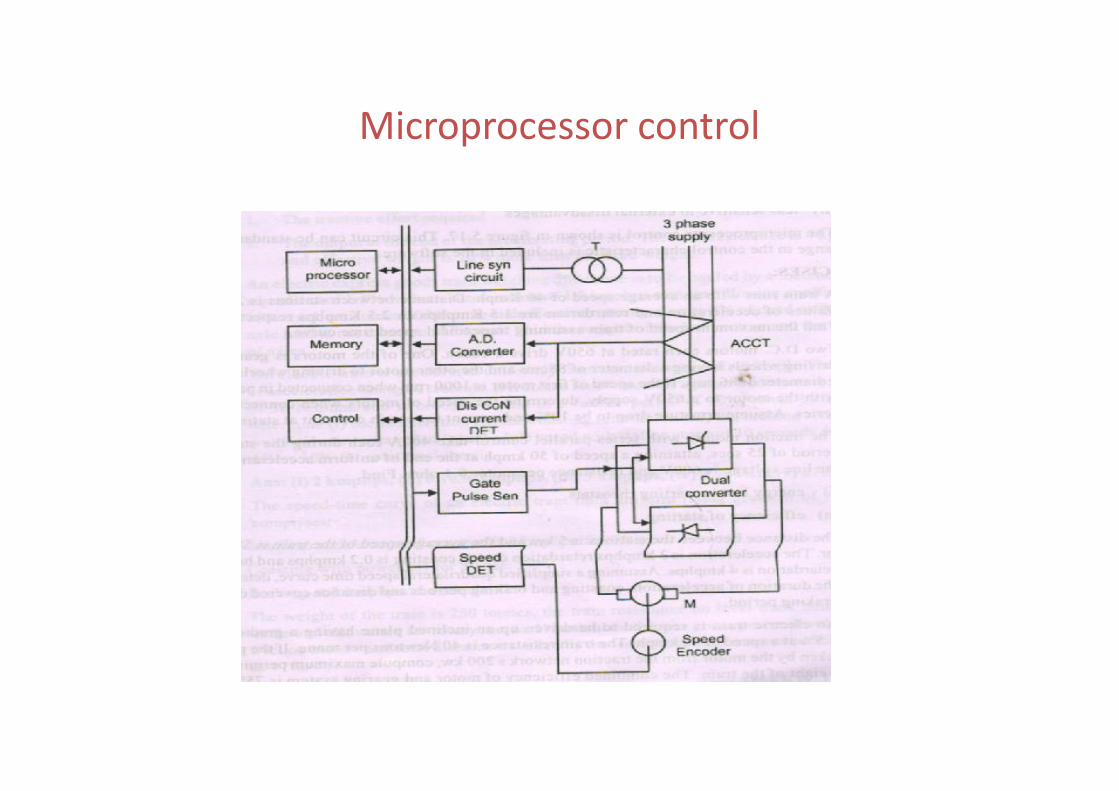
Microprocessor control


![Energy Conservation in Road Pavement Design, Maintenance ......EIE/06/039/SI2.448265 ECRPD [Type text] Energy Conservation in Road Pavement Design, Maintenance and Utilisation ECRPD](https://static.documents.pub/doc/80x56/613170e01ecc51586944bcae/energy-conservation-in-road-pavement-design-maintenance-eie06039si2448265.jpg)


