38
Electric Forces and Fields Chapter 16
| Date post: | 13-Jan-2016 |
| Category: |
Documents |
| Upload: | eugenia-cameron |
| View: | 226 times |
| Download: | 0 times |

Electric Forces and Fields
Chapter 16

Electrical Field
• Maxwell developed an approach to discussing fields
• An electric field is said to exist in the region of space around a charged object– When another charged object enters this electric
field, the field exerts a force on the second charged object
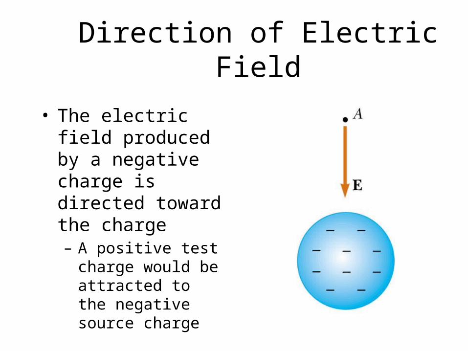
Direction of Electric Field
• The electric field produced by a negative charge is directed toward the charge– A positive test charge
would be attracted to the negative source charge

Electric Field, cont.
• A charged particle, with charge Q, produces an electric field in the region of space around it
• A small test charge, qo, placed in the field, will experience a force
See example 15.4 & 5

Coulomb’s Law
• Mathematically,
• ke is called the Coulomb Constant– ke = 8.99 x 10⁹ N m2/C2
• Typical charges can be in the µC range– Remember, Coulombs must be used in the equation
• Remember that force is a vector quantity
2
21e r
qqkF
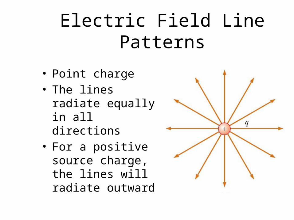
Electric Field Line Patterns
• Point charge• The lines radiate
equally in all directions
• For a positive source charge, the lines will radiate outward

Electric Field Lines, cont.
• The field lines are related to the field as follows:– The electric field vector, E, is tangent to the
electric field lines at each point– The number of lines per unit area through a
surface perpendicular to the lines is proportional to the strength of the electric field in a given region
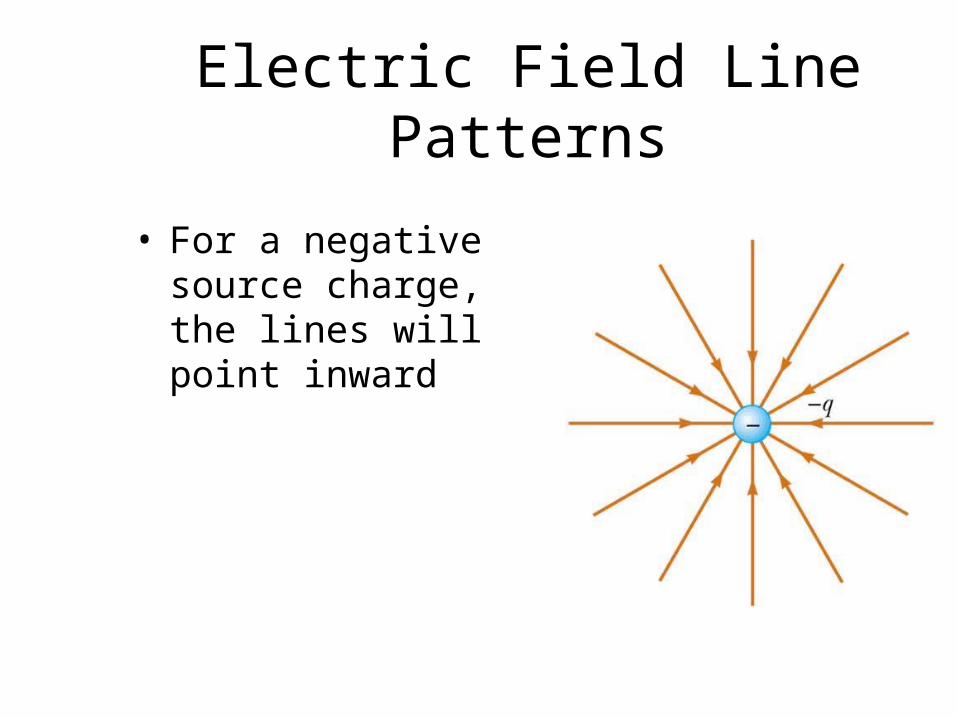
Electric Field Line Patterns
• For a negative source charge, the lines will point inward

Electric Field Line Patterns
• An electric dipole consists of two equal and opposite charges
• The high density of lines between the charges indicates the strong electric field in this region
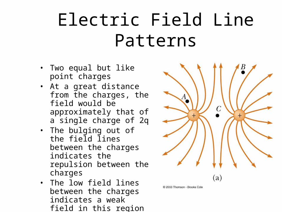
Electric Field Line Patterns
• Two equal but like point charges
• At a great distance from the charges, the field would be approximately that of a single charge of 2q
• The bulging out of the field lines between the charges indicates the repulsion between the charges
• The low field lines between the charges indicates a weak field in this region

Electric Field Patterns
• Unequal and unlike charges
• Note that two lines leave the +2q charge for each line that terminates on -q

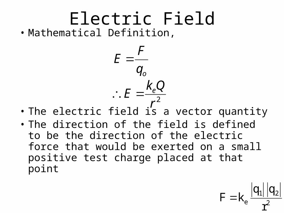
Electric Field• Mathematical Definition,
• The electric field is a vector quantity• The direction of the field is defined to be the
direction of the electric force that would be exerted on a small positive test charge placed at that point
2r
QkE
q
FE
e
o
2
21e r
qqkF
Chapter 17
Electric Energyand
Current
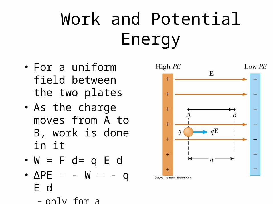
Work and Potential Energy
• For a uniform field between the two plates
• As the charge moves from A to B, work is done in it
• W = F d= q E d• ΔPE = - W = - q E d– only for a uniform field
Summary of Positive Charge Movements and Energy
• When a positive charge is placed in an electric field– It moves in the direction of the field– It moves from a point of higher potential to a
point of lower potential– Its electrical potential energy decreases– Its kinetic energy increases

Summary of Negative Charge Movements and Energy
• When a negative charge is placed in an electric field– It moves opposite to the direction of the field– It moves from a point of lower potential to a point
of higher potential– Its electrical potential energy decreases– Its kinetic energy increases
Potential Difference
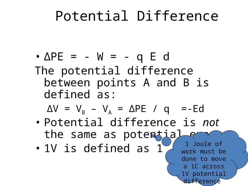
• ΔPE = - W = - q E dThe potential difference between points A
and B is defined as:ΔV = VB – VA = ΔPE / q =-Ed
• Potential difference is not the same as potential energy
• 1V is defined as 1 J/C 1 Joule of work
must be done to move a 1C across
1V potential difference
Electric Potential of a Point Charge
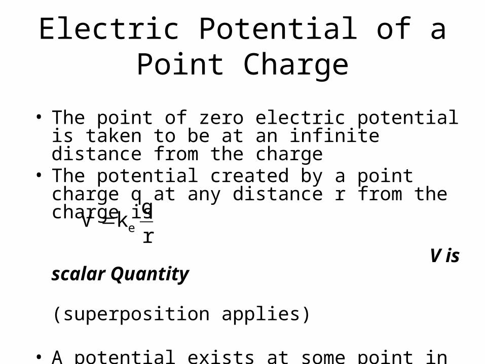
• The point of zero electric potential is taken to be at an infinite distance from the charge
• The potential created by a point charge q at any distance r from the charge is
V is scalar Quantity (superposition applies)
• A potential exists at some point in space whether or not there is a test charge at that point
• Ex. 16.4 p.540
r
qkV e
Potentials and Charged Conductors
• W = -ΔPE = -q(VB – VA), – Therefore no work is required to move a charge between
two points that are at the same electric potential i.e. W = 0 when VA = VB
• For two charges separated by rPE = ke q1q2
r Charged Surfaces and Conductors• All points on the surface of a charged conductor in
electrostatic equilibrium are at the same potential
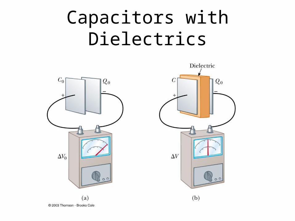
Capacitors with Dielectrics

Applications of Capacitors – Camera Flash
• The flash attachment on a camera uses a capacitor– A battery is used to charge the capacitor– The energy stored in the capacitor is released
when the button is pushed to take a picture– The charge is delivered very quickly, illuminating
the subject when more light is needed

Applications of Capacitors -- Computers
• Computers use capacitors in many ways– Some keyboards use
capacitors at the bases of the keys
– When the key is pressed, the capacitor spacing decreases and the capacitance increases
– The key is recognized by the change in capacitance
Capacitance
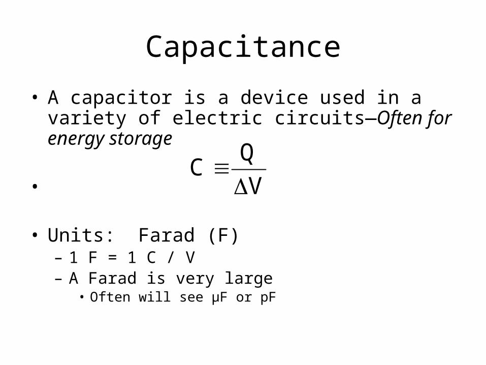
• A capacitor is a device used in a variety of electric circuits—Often for energy storage
•
• Units: Farad (F)– 1 F = 1 C / V– A Farad is very large
• Often will see µF or pF
V
QC
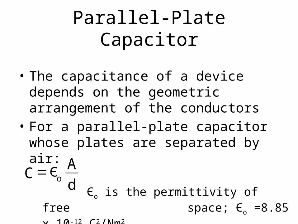
Parallel-Plate Capacitor
• The capacitance of a device depends on the geometric arrangement of the conductors
• For a parallel-plate capacitor whose plates are separated by air:
Єo is the permittivity of free space; Єo =8.85 x 10⁻¹²
C2/Nm2d
AC o
Є =
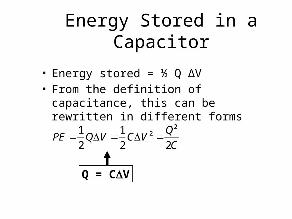
Energy Stored in a Capacitor
• Energy stored = ½ Q ΔV• From the definition of capacitance, this can be
rewritten in different forms
C
QVCVQPE
22
1
2
1 22
Q = CV

Electric Current
• Whenever electric charges of like signs move, an electric current is said to exist
• The current is the rate at which the charge flows through this surface– charges flowing perpendicularly to a
surface of area
• The SI unit of current is Ampere (A)– 1 A = 1 C/s
++
+
+
+
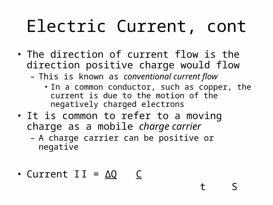
Electric Current, cont• The direction of current flow is the direction positive
charge would flow– This is known as conventional current flow
• In a common conductor, such as copper, the current is due to the motion of the negatively charged electrons
• It is common to refer to a moving charge as a mobile charge carrier– A charge carrier can be positive or negative
• Current I I = ΔQ C t S
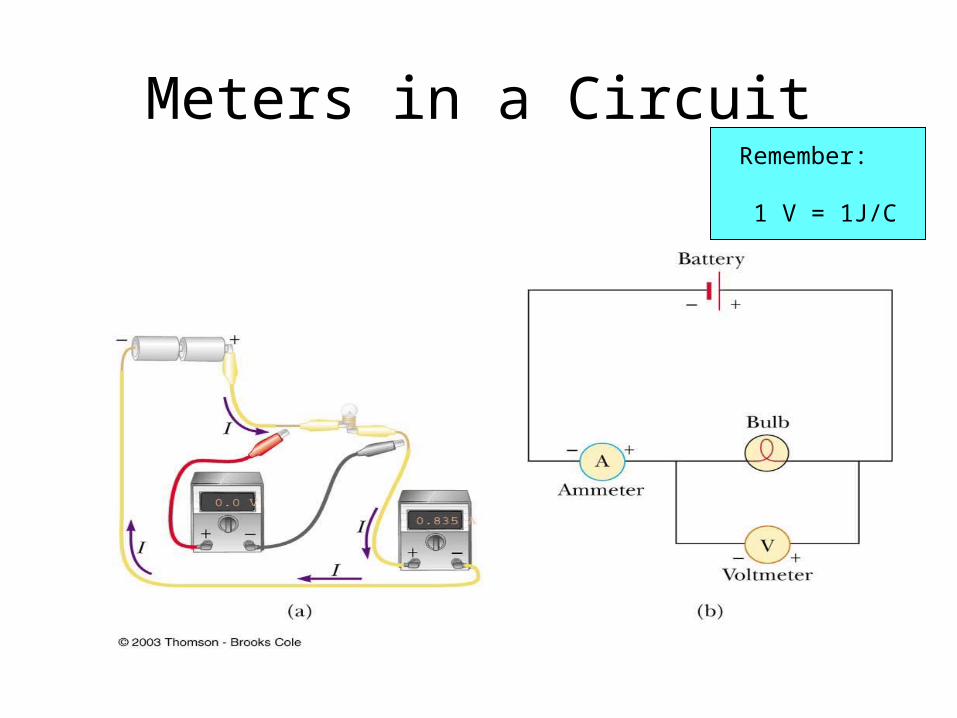
Meters in a Circuit Remember:
1 V = 1J/C

Resistance, cont
• Units of resistance are ohms (Ω)– 1 Ω = 1 V / A
• Resistance in a circuit arises due to collisions between the electrons carrying the current with the fixed atoms inside the conductor
Ohm’s Law• Experiments show that for many materials, including
most metals, the resistance remains constant over a wide range of applied voltages or currents
• This statement has become known as Ohm’s Law– ΔV = I R
• Ohm’s Law is an empirical relationship that is valid only for certain materials– Materials that obey Ohm’s Law are said to be ohmic

Ohm’s Law, cont
For an ohmic device• The resistance is
constant over a wide range of voltages
• The relationship between current and voltage is linear
• The slope is related to the resistance
V
slope=R
I

Electrical Energy and Power,
• The rate at which the energy is lost is the power
• From Ohm’s Law, alternate forms of power are
• Energy E = Pt W-s or kW-Hr
VIVt
QP
R
)V(RIP
22

Capacitors in Parallel(have the same voltage across them)
Q1 = C1ΔV Q2 = C2ΔV
Q1 + Q2 = Qtot = C1ΔV + C2ΔV
= (C1+ C2)ΔV
for capacitors in parallel Ceq= C1+ C2
Ex. 16.5 p.512

Capacitors in Series (have the same charge on each plate)
ΔV = Q Ceq
ΔVtot = ΔV1 + ΔV2
Q = Q1 + Q2
Ceq C1 C2
But Q=Q1= Q2
for capacitors in series 1 = 1 + 1Ceq C1 C2
Ex. 16.6 & 7 p. 515
Ceq = C1C2
C1 + C2

Chapter 15 Summary
2r
Qk
q
FE e
o
2
21e r
qqkF
ke is called the Coulomb Constantke = 8.99 x 10⁹ N m2/C2
εo is the permittivity of free space and equals 8.85 x 10⁻¹² C2/Nm2
oE
Q
ΦE = E A A is perpendicular to E
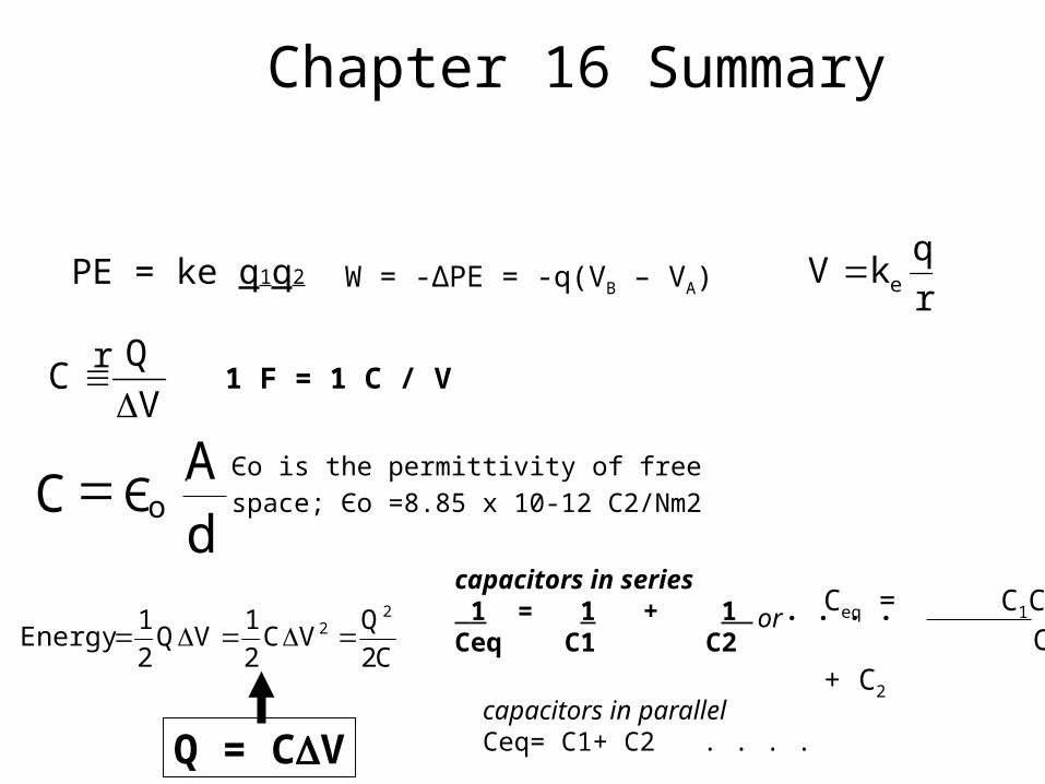
Chapter 16 Summary
V
QC
C2
QVC
2
1VQ
2
1Energy
22
Q = CV
capacitors in series 1 = 1 + 1 . . . . Ceq C1 C2
capacitors in parallel Ceq= C1+ C2 . . . .
Ceq = C1C2
C1 + C2
or
d
AC oЄ
= Єo is the permittivity of free space; Єo =8.85 x 10⁻¹² C2/Nm2
1 F = 1 C / V
r
qkV ePE = ke q1q2
r W = -ΔPE = -q(VB – VA)
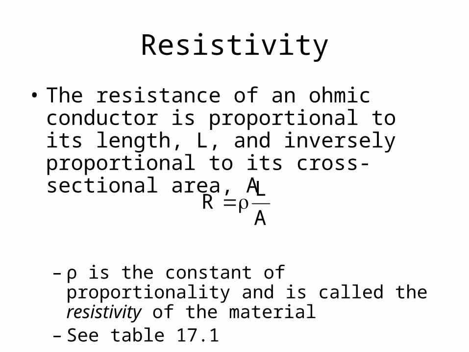
Resistivity
• The resistance of an ohmic conductor is proportional to its length, L, and inversely proportional to its cross-sectional area, A
– ρ is the constant of proportionality and is called the resistivity of the material
– See table 17.1
A
LR


