Page 1
- 45 -
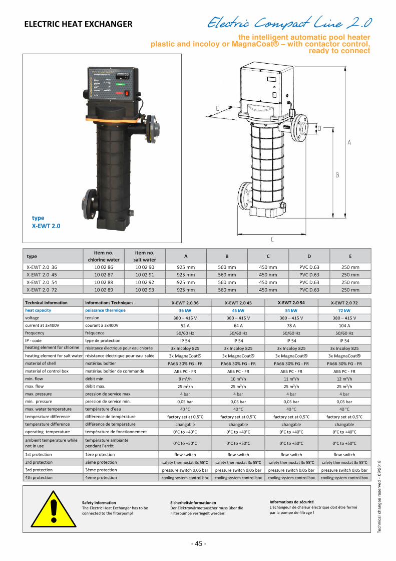
Electric Compact Line 2.0 the intelligent automatic pool heater
plastic and incoloy or MagnaCoat® – with contactor control, ready to connect
ELECTRIC HEAT EXCHANGER
type item no.
chlorine water
item no.
salt water A B C D E
X-EWT 2.0 36 10 02 86 10 02 90 925 mm 560 mm 450 mm PVC D.63 250 mm
X-EWT 2.0 45 10 02 87 10 02 91 925 mm 560 mm 450 mm PVC D.63 250 mm
X-EWT 2.0 54 10 02 88 10 02 92 925 mm 560 mm 450 mm PVC D.63 250 mm
X-EWT 2.0 72 10 02 89 10 02 93 925 mm 560 mm 450 mm PVC D.63 250 mm
Technical information Informations Techniques X-EWT 2.0 36 X-EWT 2.0 45 X-EWT 2.0 54 X-EWT 2.0 72
heat capacity puissance thermique 36 kW 45 kW 54 kW 72 kW
voltage tension 380 – 415 V 380 – 415 V 380 – 415 V 380 – 415 V
current at 3x400V courant à 3x400V 52 A 64 A 78 A 104 A
frequency fréquence 50/60 Hz 50/60 Hz 50/60 Hz 50/60 Hz
IP - code type de protection IP 54 IP 54 IP 54 IP 54
heating element for chlorine
water résistance électrique pour eau chlorée 3x Incoloy 825 3x Incoloy 825 3x Incoloy 825 3x Incoloy 825
heating element for salt water résistance électrique pour eau salée 3x MagnaCoat® 3x MagnaCoat® 3x MagnaCoat® 3x MagnaCoat®
material of shell matériau boîtier PA66 30% FG - FR PA66 30% FG - FR PA66 30% FG - FR PA66 30% FG - FR
material of control box matériau boîtier de commande ABS PC - FR ABS PC - FR ABS PC - FR ABS PC - FR
min. flow débit min. 9 m³/h 10 m³/h 11 m³/h 12 m³/h
max. flow débit max. 25 m³/h 25 m³/h 25 m³/h 25 m³/h
max. pressure pression de service max. 4 bar 4 bar 4 bar 4 bar
min. pressure pression de service min. 0,05 bar 0,05 bar 0,05 bar 0,05 bar
max. water temperature température d’eau 40 °C 40 °C 40 °C 40 °C
temperature difference différence de température factory set at 0,5°C factory set at 0,5°C factory set at 0,5°C factory set at 0,5°C
temperature difference différence de température changable changable changable changable
operating temperature température de fonctionnement 0°C to +40°C 0°C to +40°C 0°C to +40°C 0°C to +40°C
ambient temperature while
not in use
température ambiante
pendant l'arrêt 0°C to +50°C 0°C to +50°C 0°C to +50°C 0°C to +50°C
1st protection 1ère protection flow switch flow switch flow switch flow switch
2rd protection 2ème protection safety thermostat 3x 55°C safety thermostat 3x 55°C safety thermostat 3x 55°C safety thermostat 3x 55°C
3rd protection 3ème protection pressure switch 0,05 bar pressure switch 0,05 bar pressure switch 0,05 bar pressure switch 0,05 bar
4th protection 4ème protection cooling system control box cooling system control box cooling system control box cooling system control box
Safety Information
The Electric Heat Exchanger has to be
connected to the filterpump!
Sicherheitsinformationen
Der Elektrowärmetauscher muss über die
Filterpumpe verriegelt werden!
Informations de sécurité
L'échangeur de chaleur électrique doit être fermé
par la pompe de filtrage !
type
X-EWT 2.0
Tech
nic
al
ch
an
ge
s r
ese
rve
d -
09
/20
18
Page 2
- 1 -
Assembly
and Installation Instructions
Electric Heat Exchanger of the Series X-EWT 2.0 36-45-54-72
If you do not pay proper attention to these installation instructions the manufacturer cannot accept liability for any resulting
damage to the device itself, the environment, property, or personal injury.
Your safety is our concern!
These Electric Heat Exchangers consist of a non-flammable plastic shell and three already mounted electric heating
elements which are made out of Incoloy 825 or coated with a sea water resistant MagnaCoat® coating.
1. Purpose:
These Electric Heat Exchangers are made to heat up bathing water in swimming pools and whirlpools while
the pump is running. It is not permitted to change and/or modify the device without consulting the
manufacturer.
2. Safety Warning:
2.1 This device has not been designed for use by individuals (including children) with physical, mental or sensory
disabilities, or people who lack the necessary experience and/or knowledge unless under the supervision of
someone entrusted with their safety or instructed by that person in how the device should be used.
2.2 Attention: never open the control box without disconnecting it carefully from the electrical power supply
and to be secured against unintentional switching on.
3. Important:
3.1 Anybody involved with the installation, start-up, use, maintenance, and/or repair of the Electric Heat
Exchanger must be qualified and carefully follow the instructions.
3.1 Only a specialized electrical technician (VDE 0105) may operate the device following the DIN VDE 0100
safety standards.
4. Fire Hazard:
4.1 It is forbidden to install the device near flammable materials.
4.2 Do not use covers or insulation.
5. Safety Device:
5.1 This Electric Heat Exchanger is protected by seven safety switches.
5.2 Unless the client specifically requires less safety features, these electric heat exchangers are standard
equipped with
a) electric temperature regulator 1-40°C
b) three times with a safety thermosat 55°C, with a reset button on the outside
c) pressure switch
d) flow switch
e) overheating protection for the electric box
Do not operate the device through the flow switch but through the filter pump. See 11.7 and the circuit
layout!
5.3 If there is lack of water or overheating, the safety devices will switch the heat exchanger off.
6. Corrosion Prevention. 6.1 The electric heat exchanger has to be installed after the filter.
6.2 Be careful not to wash any metals into the Electric Heat Exchanger when connecting it to the water circuit.
Before activation the water pipes need to be full and without air.
6.3 The electric heat exchanger must be mounted in a way which allows the device to be always full of water.
During off season the heat exchanger can also be completely drained. Do not put a block valve between
electric heat exchanger and pool. If necessary a check valve can be put.
6.4 To avoid corrosion do not exceed the following water parameters.
chlorine water: chlorine content: max. 500 mg/l salt water: chlorine content: max. 3000 mg/l
free chlorine max. 1 mg/l free chlorine: no limit
pH max. 6,8 – 7,8 pH: max. 6,8 – 7,8
salt: max. 3,5%
Attention: Disinfection devices should be installed after the electric heat exchanger and in a way which
prevents chemicals or gases to enter while it is switched off.
Page 3
- 2 -
7. Frost:
During frost the Electric Heat Exchanger has to be completely empty.
8. Please Note:
The specific water resistance at 15°C may not be below 550 kg OHM x cm. When the limits are properly
taken into consideration (see above), the water resistance will remain between 1,5 Mega OHM x cm and 550
Kilo OHM x cm.
9. Operating Pressure:
Do not exceed the 4 bar operating pressure, otherwise the electric heat exchanger could start leaking.
10. Minimal Quantity of flow, minimal pressure in the shell:
9000 l/h , 0,05 bar for model X-EWT 2.0 36
10000 l/h , 0,05 bar for model X-EWT 2.0 45
11000 l/h , 0,05 bar for model X-EWT 2.0 54
12000 l/h , 0,05 bar for model X-EWT 2.0 72
11.Safety Device:
11.1 Before starting the Electric Heat Exchanger install an FI – safety switch (0,03 A) and a circuit breaker into the
power supply.
11.2 The Electric Heat Exchanger must be connected to the ground wire
11.3 The device has to be connected to permanently installed pipes.
11.4 For the electric connection it is necessary to use a H07 RNF cable.
11.5 While cross sectioning the cable, please consider VDE 0100.
11.6 It is imperative that the controller of the Electric Heat Exchanger had to be locked electrically through the
filter pump. (see circuit diagram)
12. Mode of Operation:
If the device was connected by following the circuit diagram, with pump lock, the following lock mode of
operation can be expected:
12.1 Step 1: put the operating switch on position „I“
12.2 Step 2: Start-up the filter pump and set the electric temperature control to the desired water temperature
(eg. 25°C). The necessary reference for the set up you can find in point 15.
12.3 As soon as the filter pump starts up, the lock and the flow switch will react. The display will be activated; the
red control lamp will switch on. With the default setting the heating elements will be switched onto the
circuit after a five minute delay. Now the green control lamp switches on, too.
12.4 As soon as the desired water temperature is reached, the heating elements will be switched off by the
temperature control. The green light switches off. The display shows the set temperature. The red light will
be on as long as there is no disturbance. All active lights and the display will switch off with the filter pump.
12.5 If the display switches off while the filter pump is running, there is not enough water flow. Another reason
could be that overheating took place and the safety thermostats switched off the device.
12.6 Set the operating switch and the circuit breaker to „0“ and find out why the overheating took place.
12.7 Attention: Never open the electric box without totally disconnecting the electric heat exchanger from the
circuit. Make sure it won’t turn on unintentionally. If necessary to switch on the device again, don’t forget to
Installation above water level Installation below water level
Water Level
Water Level
Page 4
- 3 -
push the reset – buttons of the safety-thermostats. You can find them under the removable black cover on
the electric box (left side).
12.8 The start delay is active after each new start-up. This feature is preventing the controllers from hammering
in the limit range and is therefore preventing damage. It is factory set at 5 minutes.
12.9 Summary: During the filtation time the red control lamp and the display have to be on. If that is not the case
a disturbance is going on! The bathing water temperature is shown on the display.
13.Circuit Diagram:
14. Instruction for the Digital Electric Temperature Regulator Ascon Z31Y
14.1 Contacts 1+2 supply 230V AC 50/60 Hertz
14.2 Contacts 10+11 Temperature sensor
14.3 Contacts 10+12 Temperature sensor for the electric box
14.4 After turning on the device a short test run will be shown on the
display, then it will show immediately the water temperature.
After the filter pump switched on the bathing water
temperature will be shown.
15. Setting of the desired bathing water
temperature:
15.1 Briefly press the button „P“. The display will show alternately
“SP” and the set point for the bathing water temperature.
15.2 By pressing the up or down arrow buttons ( oder ) the set point (bathing water temperature) can
be changed. The minimum temperature in 1°C and the maximum 40°C.
15.3 To confirm press „P“ or the selcted number will be saved automatically after 15 seconds.
16. Setting the Differential Temperature:
16.1 The difference is factory set at 0,5°C. When the bathing water has reached the set temperature, the heating
will switch off until the bathing water temperature has cooled down 0,5°C.
16.2 This differential value can be changed. By keeping the button „P“ pressed you will get to the menu . „r.d“
will appear. Press „P“ again shortly and the set value appears which can now be changed with the arrow
buttons. The range is from 0,1°C to 30°C and can be adjusted in 0,1°C increments. Confirm by pressing „P“
again.
circuit
breaker
fault
current
protection
switch
0,03A
heating
elements safety thermostat 1
safety thermostat 2
safety thermostat 3
flow switch
NTC
NTC
operating
switch
fan
contactor contactor
power
supply
12V
bimetal switch
pressure switch
filter pump interlock device
digital temperature
controller
red
green
fuse
Page 5
- 4 -
16.3 Exiting the menu will happen automatically after 30 seconds.
17.Changing the Heating Elements:
17.1 Please pay attention when you loosen or tighten the wire connections on the heating element. The lower
nut needs to be blocked with a second wrench in order to prevent damages on the connections of the
heating elements.
17.2 Please keep in mind the correct positioning of the heating elements which can be located looking at the
positioning of the thermowells.
18.Please save these Installation and Assembly Instructions and file them for later use. Thank you!
09.05.19 max dapràKG-daprà andreas&Co Grafenweg2 I-39050 Völs
Page 6
- 5 -
19.Troubleshooting Chart:
Problem Possible Causes Solutions/Helpful Hints
Display is not illuminated Low/no water flow Check the minimum water flow
Red lamp on the on/off switch One or more Reset the three safety thermostats
is on safety thermostats are
switched off
Red lamp on the on/off switch Defective fuse Check if the fuse is blown
is not lit even though there is
power available Defective on/off switch Check if the device still works;
in the control circuit maybe the switch has to be changed
Device doesn't switch on The start delay was not taken Attention: as long as the red dot on the
into consideration lower left of the display is blinking, the
the device won't switch on because it
has a 5 min. start delay
The temperature is set Check the temperature setting
incorrectly "SP". It has to be set higher than the
bathing water temperature
Device is not heating Circuit breaker or Activate both circuit breakers
even though the controller FI-safety switch is interrupted
works normally
Green LED-lamp is not Defective LED-lamp Check if the device is working anyway.
illuminated even though If the device is working,
the device should be heating change the LED-lamp
The device stops heating in the The temperature in the Check the temperature in the controller:
middle of the cycle controller is too high when pressing "U" the temperature inside
but after a while it switches the contoller will be shown
on automatically Attention: at 56°C the the device switches off
automatically and stays off until it
cooled down to 48°C
Clean the 2 filters of the ventillation system
Fan or power supply 12V Change the fan or the
are broken power supply 12V
FI-safety switch or Heating elements are broken Call a certified electrician
circuit breaker switched off Contol-device is broken
Page 7
- 6 -
Electric heat exchanger
X-EWT 2.0
EC – declaration of conformity
Herewith we declare that the products
Series:
comply with the following provisions:
Make:
Operating medium: liquid
Max. service pressure shell:
Test pressure shell:
Norms:
Date:
Signatory: Andreas Daprá
Daprà
4 bar
5,72 bar
09.05.2019
EN 60335-2-35:2016 / DIN EN 13732-1/DIN EN 60335-1 / DIN EN 60335-
2-15 /DIN EN 60335-2-35/DIN EN 60730-1/DIN EN 60730-2-9/
2006/95/EC Low voltage directive