Technical Manual Instructions for installation, operation and maintenance 748 ELECTRIC HEATER CONTROL (EHC) CABINET For ViscoSense ® , ViscoSense ® 2 (Viscosity control system) Publication nr TIB-748-GB-0711 Supersedes TIB-748-GB-0307
Transcript
Technical Manual
Instructions for installation, operation and maintenance
748 ELECTRIC HEATER CONTROL (EHC) CABINET
For ViscoSense® , ViscoSense®2 (Viscosity control system)
Publication nr TIB-748-GB-0711 Supersedes TIB-748-GB-0307
2. SYSTEM DESCRIPTION ................................................................ 4 2.1 Electric heater control cabinet (EHC cabinet) .............................................. 4 2.2 System components .................................................................................... 5
3. TECHNICAL SPECIFICATIONS ..................................................... 6 3.1 Cabinet construction .................................................................................... 6
7. OPERATING INSTRUCTIONS OF COMPLETE SYSTEM ............ 9 7.1 Operating controls ........................................................................................ 9 7.2 Operating instructions of the controller ........................................................ 9
7.2.1 Normal operation ................................................................................ 9 7.2.2 Beacon Display and Description ....................................................... 10
7.3 The operator buttons .................................................................................. 10 7.4 Operation levels and corresponding operation menus ............................... 11
7.4.1 Operational Level 1 (see par. 7.8.2 and 7.8.3) .................................. 11 7.4.2 Operational Level 2 (see par. 7.8.2 and 7.8.3) .................................. 11 7.4.3 How to change from Level 1 to Level 2 and visa versa ..................... 11
7.5 To set the required viscosity or temperature setpoint ................................ 12 7.5.1 Changing from viscosity control to temperature control (or visa versa)12
7.6 To select manual operation ........................................................................ 14 7.6.1 How to change controlling output in manual operation ..................... 14 7.6.2 To select manual operation ............................................................... 14
7.7 Alarm Indication ......................................................................................... 15 7.7.1 Absolute alarms ................................................................................ 15 7.7.2 To Acknowledge an Alarm ................................................................ 16
7.9 Start-up/Operating instrictions ................................................................... 20 7.9.1 Initial start-up .................................................................................... 20 7.9.2 Routine start-up ................................................................................ 21 7.9.3 Routine start-up with diesel oil and change over to HFO .................. 21 7.9.4 Routine start-up on heavy fuel .......................................................... 22 7.9.5 Shut-down with change-over from HFO to diesel oil ......................... 22 7.9.6 Fine tuning to process ....................................................................... 22
15. TROUBLE SHOOTING ............................................................. 26 15.1 Diagnostic information ............................................................................ 26 15.2 Trouble shooting related to the system ................................................... 26 15.3 Trouble shooting related to the EHC cabinet .......................................... 27
This manual contains instructions for installation, operation and maintenance of the Electric Heater Control Cabinet (EHC Cabinet). For instruction, operation and maintenance information of associated equipment supplied by VAF Instruments B.V., refer to the separate manual supplied with those products. This manual contains important information for the installer, the operator and for your maintenance department.
To ensure safe and correct installation and operation, read this manual completely before installing the equipment and starting operations.
For any additional information contact: VAF Instruments B.V. Tel. +31 78 618 3100 Vierlinghstraat 24, 3316 EL Dordrecht Fax +31 78 617 7068 P.O. Box 40, NL-3300 AA Dordrecht E-mail: [email protected] The Netherlands Internet: www.vaf.nl Or your local authorized VAF dealer. Their addresses can be found on www.vaf.nl
1.2 SYMBOLS
The following symbols are used to call attention to specific types of information.
A warning to use caution! In some instances, personal injury or damage to the EHC cabinet may result if these instructions are not followed properly.
An explanation or information of interest.
1.3 COPYRIGHT
This technical manual is copyrighted with all rights reserved. While every precaution has been taken in the preparation of this manual, no responsibility for errors or omissions is assumed. Neither is any liability assumed for damages resulting from the use of the information contained herein. Specifications can be changed without notice. ViscoSense® is a registered trademark of VAF Instruments B.V.
4
2. SYSTEM DESCRIPTION 2.1 ELECTRIC HEATER CONTROL CABINET (EHC CABINET)
The EHC cabinet has been designed for automatic control of the injection Viscosity of heavy fuel oil. The control action is realised by heating the fuel oil step by step to an appropriate temperature. The built-in viscosity/temperature controller with his programmed setpoint values activates more or less heater relays. Up to six stages are controlled by means of relays. The first stage is controlled by means of time proportional control. The function of this is to enable a linear control of power from zero to a maximum value. The power required under a certain load is adjusted by switching “ON” or “OFF” a number of stages, while the remaining fraction is added by the time-proportional control. The viscosity and temperature of the fuel oil will be measured with our VAF ViscoSense®, ViscoSense®2 system. For further details see Technical Manual 756 and TIB-761.
Figure 1 Typical example of system lay-out
5
2.2 SYSTEM COMPONENTS
The EHC cabinet consists of: 1 - Viscosity/temperature controller 2 Signal lamp main supply 3 thru 8 - Signal lamps heaters 9 - Lamp heater temperature alarm 10 - Main switch
Figure 2 EHC Cabinet front cover
6
3. TECHNICAL SPECIFICATIONS
3.1 CABINET CONSTRUCTION
Supply voltage 380 or 440 Vac, 3ph 50/60Hz
(Fluctuations should not exceed ± 10% of the nominal value).
Power consumption 250 VA Input
4-20mA
Measured viscosity and temperature signals from Interface box.
Output Power Alarms Heater Supply Power
230 Vac 50/60Hz to Interface box High/low alarm viscosity, high/low alarm temperature and overheat contact from electric heater Six heater elements and one thermostat sensor. 380 or 440 Vac Max. 10.0 kW @ 380Vac, max. 11.5 kW @ 440Vac
Ambient temperature 0 … + 50°C Humidity range 0 – 80% RH Protection class IP 55 Mounting Wall mounting
Cable connections
Power supply Input signals Output signals
cable diameter 18–25 mm (M32 x 1.5) cable diameter 6-12 mm (M20 x 1.5) cable diameter 9-16 mm (M25 x 1.5)
Fuses: Supply to heater elements Supply to heater element Output of transformer
6 automatic current breakers, 20A 2 fuses of 2A 1 fuse of 6.3A (24Vac), 1 fuse of 2A (230Vac) and 1 fuse of 1A to protect 24Vac, while one of the bulbs could have a short circuit.
Installation category 1 acc. to IEC 1010-1 Pollution degree 1 acc. to IEC 664 Material cabinet sheet steel Dimensions 760 x 600 x 350 mm (H x W x D) Colour Munsell 5Y 7/1 (RAL 7032) Ventilation requirements no special requirements Weight 40 kg
7
4. SAFETY INSTRUCTIONS 4.1 SAFETY PRECAUTIONS
To ensure the safety of personnel and EHC cabinet: Always follow the safety and installation recommendations in this manual. Always use personal protective means when working with hot, aggressive and toxic
process liquids. Always use insulated tools when working on electrical installations. Ensure that local safety regulations are met when installing and operating the EHC cabinet. All personnel who operate and service the EHC cabinet should read this manual completely
and make themselves acquainted with this cabinet before installing or operating.
5. UNPACKING Let the EHC cabinet acclimatize in the location where it is going to be installed for at least one hour inside the shipment box. This is to avoid moisture built-up inside the cabinet. Due to the weight of the EHC cabinet use proper tools to take it out of the box. When the cabinet is taken out of the box, please leave the special protection (if any) that is mounted on the cabinet as long as possible in place to avoid any damage to the enclosure, controller and other parts mounted on the front cover of the EHC cabinet.
6. INSTALLATION
6.1 TO RECORD NAMEPLATE DATA
Before installing an EHC cabinet, record type and serial number as stamped on the nameplate located on the right upper corner of the front door of the EHC cabinet.
Always quote the EHC cabinet serial number, type no. and if applicable the variant number when contacting the factory or local service representative.
Figure 3 An EHC cabinet may be part of a complete VAF viscosity/temperature control system. For information and instructions covering the other components of this system, refer to separate Technical Manuals as supplied with this cabinet.
8
6.2 MECHANICAL INSTALLATION
1. Before installation inspect the EHC cabinet for any visible signs of damage caused during transport.
2. Install the EHC cabinet in a suitable location, free from excessive vibrations, humidity and excessive temperature variations.
3. Allow sufficient space for installation of the cables, opening and closing of the door, operating the controller and for servicing.
4. Refer to drawing 0899-3075-3 sheet 5 of 6 for dimensions and mounting position of the brackets.
6.3 ELECTRICAL INSTALLATION
In order to maintain proper EMC protection a shielded cable should be used for all external signal connections such as; 4... 20 mA output signals and/or relay contacts. Recommended cable, twisted pair individually screened conductor (24 AWG or 0.25mm2) stranded wire, overall PVC insulated. Wire cross section max. 1.5 mm2.
6.3.1 Cable specifications
Main supply 4 x 2.5 mm²
Output 2 x 0.5 mm² (5 x) for high/low viscosity alarm, high/low temperature alarm and
viscosity – temperature control indication. 4 x 2.5 mm² (6 x) for the heater stages 3 x 1.0 mm² for the electric heater – overheat alarm 3 x 1.0 mm² for the thermostat sensor of the electric heater (Shielded cable)
Input 24 AWG or 0.25mm² (shielded cable) cable from Interface box.
9
7. OPERATING INSTRUCTIONS OF COMPLETE SYSTEM
Figure 4
7.1 OPERATING CONTROLS
Refer to drawing 0899-3075-3 sheet 5 of 6 for front door layout. The electric heater cabinet and control unit can be operated by means of the following switches on the front door: Main supply switch (10) Switches main power “ON” or “OFF”. Controller (1) Main operator user interface with system Signal lamp main supply (2) (White) Indicates mains power is “ON” or “OFF” Signal lamp heater stages (3 8) (Blue) Indicates which of the heater stages are active Heater temperature alarm (9) (Red) Indicates if the heating unit overheats (thermostat)
7.2 OPERATING INSTRUCTIONS OF THE CONTROLLER
7.2.1 Normal operation
Switch on the controller. Following a brief self-test sequence, the controller will start up in AUTO mode and Operator Level 1. This section describes the operation of the controller in this level. AUTO is the normal closed loop viscosity or temperature control mode which means that the output power is adjusted automatically by the controller in response to the measurement from the input sensor. In this mode the format of the display for a new instrument is shown below. It is called the HOME display.
10
7.2.2 Beacon Display and Description
MAN Illuminates when manual mode active ALM If an alarm occurs the red alarm beacon flashes. This is accompanied by a message
showing the source of the alarm, for example ‘Boiler overheating’. To acknowledge press and . The message disappears. If the alarm condition is still present the beacon lights continuously. When cleared it will extinguish. A full description of the alarm operation is given in section 7.7
IR Flashes when infra red communications active
7.3 THE OPERATOR BUTTONS
Page Scroll Lower Raise
A/MAN This button can be disabled
Manual operation means that the controller output power is adjusted by the user. The input sensor is still connected and reading the PV but the control loop is open. When pressed, this toggles between automatic and manual operation. If the controller is in manual mode, ‘MAN’ light will be indicated If the controller is powered down in Manual operation it will resume this mode when it is powered up again.
Press to select new PAGE headings (several menus)
Press to select a new parameter in the page
Press to decrease an analogue value, or to change the state of a digital value
Press to increase an analogue value, or to change the state of a digital value
Current level of access
Indication shown Lev1 Lev2
Config.
Indicator beacons (listed below)
Process Variable (PV) Setpoint (SP) Message display
11
7.4 OPERATION LEVELS AND CORRESPONDING OPERATION MENUS
7.4.1 Operational Level 1 (see par. 7.8.2 and 7.8.3)
a) HOME display b) Set point Menu c) Output Menu
7.4.2 Operational Level 2 (see par. 7.8.2 and 7.8.3)
a) HOME display b) Set point Menu c) Output Menu d) Viscosity Channel Menu (Controlling parameters) e) Temperature Channel Menu (Controlling parameters) f) Alarm Settings
Configuration Level Factory configuration level is only accessible by VAF Instruments B.V.
7.4.3 How to change from Level 1 to Level 2 and visa versa
From HOME display,
1. Press and hold down for a few seconds.
2. ACCESS display will now appear.
3. Press to change Level1 to Level2
4. After a few seconds a pass code is required.
5. Press to change pass code 0 to 2
6. The controller will after a few seconds automatically accept the pass code and jump back to the Home page.
7. The level of access is now changed from Level 1 to Level 2
8. To change back from Level 2 to Level 1 Press and hold down for a few seconds.
9. ACCESS display will now appear.
10.Press to change Level 2 to Level 1
11.After a few seconds the level of access will change from level2 to level1 and the controller will jump automatically back to the HOME display.
12
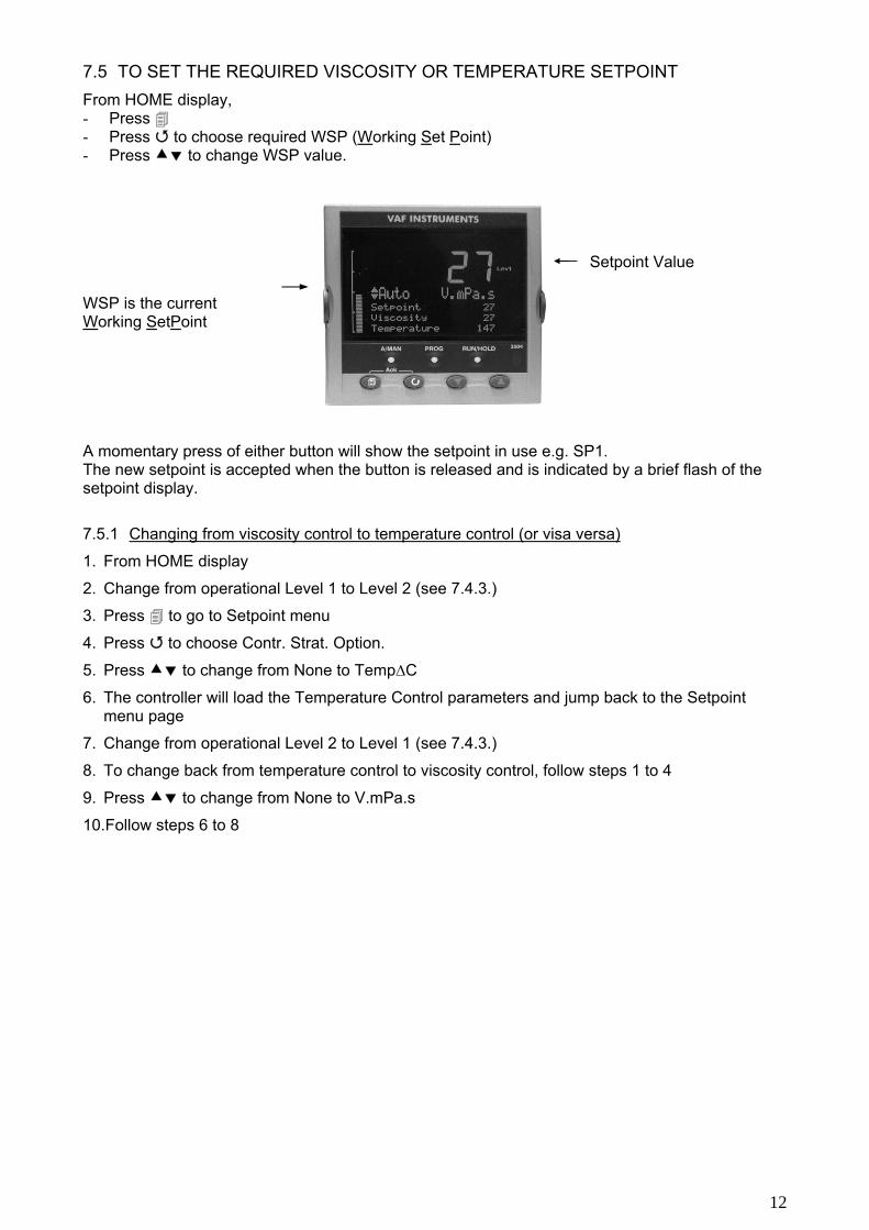
7.5 TO SET THE REQUIRED VISCOSITY OR TEMPERATURE SETPOINT
From HOME display, - Press - Press to choose required WSP (Working Set Point) - Press to change WSP value. WSP is the current Working SetPoint A momentary press of either button will show the setpoint in use e.g. SP1. The new setpoint is accepted when the button is released and is indicated by a brief flash of the setpoint display.
7.5.1 Changing from viscosity control to temperature control (or visa versa)
1. From HOME display
2. Change from operational Level 1 to Level 2 (see 7.4.3.)
3. Press to go to Setpoint menu
4. Press to choose Contr. Strat. Option.
5. Press to change from None to Temp∆C
6. The controller will load the Temperature Control parameters and jump back to the Setpoint menu page
7. Change from operational Level 2 to Level 1 (see 7.4.3.)
8. To change back from temperature control to viscosity control, follow steps 1 to 4
9. Press to change from None to V.mPa.s
10.Follow steps 6 to 8
Setpoint Value
13
Contr. strat. = Controller Strategy Controller used in EHC cabinet: Contr. Strat. will only appear in level 2.
14
7.6 TO SELECT MANUAL OPERATION
From HOME display,
1. Press A/MAN Button
2. Controller is now in Manual operation
Press button. ‘Man OP’ will be displayed ‘MAN’ beacon will be lit on
Bar graph for output level
7.6.1 How to change controlling output in manual operation
From Home Display.
1. Make sure controller is in manual operation (see 7.6).
2. Press twice.
3. Output menu display will now appear.
4. Press to choose Output option.
5. Press to increase/decrease the output. The bar graph output and percent output indication will change accordingly. The controller will, after a few seconds, automatically jump back to the Home page or press and (Ack) simultaneously to go back to the Home Page immediately.
7.6.2 To select manual operation
Bar graph for output % (level 1).
1. Press to choose output %.
2. Press to increase/decrease the output.
Upper display shows Actual Temperature (or Process Variable ‘PV’) Lower display shows output power
15
7.7 ALARM INDICATION
If an alarm occurs it is indicated as follows:
The red alarm (ALM) beacon in the top left of the display flashes
Alarm number is indicated together with the flashing
A default message or a pre-programmed message appears showing the source of the alarm.
Invitation to acknowledge the new alarm.
7.7.1 Absolute alarms
Controller Alarms PV Input (SBreak) Sensor break no input signal available AnAlm1 Viscosity high alarm AnAlm2 Temperature high alarm AnAlm3 Viscosity low alarm AnAlm4 Temperature low alarm
16
7.7.2 To Acknowledge an Alarm
Press and (Ack) together. The action, which now takes place, will depend on the type of latching, which has been configured
Non Latched Alarms
If the alarm condition is present when the alarm is acknowledged, the alarm beacon will be continuously lit. This state will continue for as long as the alarm condition remains. When the alarm condition disappears the indication will also disappear. Display indication: 1: Abs Hi 2: Abs Lo This up/down sign will be followed by the alarm setpoint value. If a relay has been attached to the alarm output, it will de-energise when the alarm condition occurs and remain in this condition until the alarm is acknowledged AND it is no longer present. If the alarm condition disappears before it is acknowledged the alarm indication disappears as soon as the condition disappears.
Automatic Latched Alarms
The alarm continues to be active until both the alarm condition is removed AND the alarm is acknowledged. The acknowledgement can occur BEFORE the condition causing the alarm is removed.
Manual Latched Alarms
The alarm continues to be active until both the alarm condition is removed AND the alarm is acknowledged. The acknowledgement can only occur AFTER the condition causing the alarm is removed.
17
7.8 CONTROLLER OPTIMIZATION
7.8.1 Manual optimization
An optimum adaptation of the control parameters (P,I) is necessary in order to balance an appearing deviation as quickly, non-oscillating and exactly as possible, according to the give operation conditions. Generally these adjustments require a lot of professional knowledge that cannot be replacement by this brief information. The following information is for help purpose only: P = proportional band Pb (%): Lower value = longer impulses, more sensitive reaction Higher value = shorter impulses, less sensitive reaction Examples - Oscillating temperature without distinct initial overshot: Pb too low;
- The set point is reached very slowly after initial exceeding: Pb too high.
I = integral action time Ti (min): Lower value = shorter impulse gaps, faster balancing Higher value = longer impulse gaps, slower balancing Examples the set value is reached very slowly without overshooting:
Tn too high; high initial overshot followed by fading oscillation: Tn too low.
18
7.8.2 Parameter navigation diagram level 2
To access Level 2 see paragraph
Home
→
Setpoint
→
Output
→
Viscosity Channel
→
TemperatureChannel
� ↓
� ↓
� ↓
� ↓
Viscosity Sp WSP setting Output %
Pb 34
Pb 34
� ↓
� ↓
� ↓
� ↓
Temperature Sp
WSP setting
Aut/Man Status
(indication) Ti
260 Ti
260
� ↓
� ↓
� ↓
� ↓
Temperature or
Viscosity control
Op on Time 2.00
High Viscosity Alarm
(Indication) 16 mPa.s
High Temperature
Alarm (Indication) 150°C
� ↓
� ↓
Hysteres high
0
Hysteres high
0
� ↓
� ↓
Low Viscosity Alarm
(Indication) 12 mPa.s
Low Temperature
Alarm (Indication) 50°C
� ↓
� ↓
Hysteres low
0 Hysteres low
0 (Bold and underlined indications are factory settings)
19
7.8.3 Parameter names
Name Description Set point Menu Viscosity Sp Controlling set point (see par 7.4) Temperature SP Controlling set point (see par 7.4) Contr. Strat Controller Strategy. To set controller in Viscosity or Temperature
control Output Menu Output % Control valve indication in Automatic mode.
Control valve indication and operation in Manual mode Aut/Man Status Operational status of controller OP on Time Minimum ON time of output pulse Viscosity Channel Pb Proportional band (see par 7.7.1.) Ti Integral time (see par 7.7.1.) Band Alarm Indication of band alarm in units Hysteres Alarm 1 Hysteresis in units Temperature Channel Pb Proportional band (see par 7.7.1.) Ti Integral time (see par 7.7.1.) Band Alarm Indication of band alarm in units Hysteres Alarm 2 Hysteresis in units Alarm setting 1: Abs Hi Alarm Absolute Alarm 1 setting in units 2: Abs Lo Alarm Absolute Alarm 2 setting in units
20
7.9 START-UP/OPERATING INSTRICTIONS
7.9.1 Initial start-up
Initial start-up should always be done with diesel oil. Refer to figure 4.
1. Fill the complete fuel system with diesel oil
2. Open block valves (K and M) and bypass valve (L) in fuel line around ViscoSense®, ViscoSense®2 assembly.
3. Allow diesel oil to enter fuel system and vent the fuel system.
4. Start the booster pump in fuel system and after approximately 15 minutes close bypass valve (L).
6. Be sure the controller is set for viscosity control, if not see chapter 7.5.1.
7. Set “viscosity set point” value to 5 cSt / mPa.s and “temperature set point” value to 20°C in the controller.
8. Depending upon the viscosity and temperature of the liquid it can take up to 30 seconds before the first reading appears. This is due to the automatic signal gain control.
9. Check operation of the viscosity/temperature controller as follows:
a. Set the controller to temperature control (refer to chapter 7.5.1)
b. Increase temperature set point in steps. Wait between each step and observe the result.
Caution: with diesel oil in the system never exceed a temperature of 50°C.
Increasing the temperature set point will cause heater stage 1 to activate with an increasing duty cycle, as shown by an increasing flashing intensity of the indicating lamp (3) of heater stage 1. A further increase of the temperature set point (do not exceed 50 °C!) will result in: - Switching on of heater stage 2, while at the same time the duty cycle of stage 1
reduces the duty cycle of stage no. 1 increases again as the set point is further increased;
- Switching on of heater stage 3 in addition to stage 2, while the duty cycle of stage 1 reduces and then increases again as the set point is further increased;
- etc., until maximum power output is achieved when all heater stages are activated. c. Decrease temperature set point to 20°C.
NOTE: Due to the integrating action of the controller during the previous procedures, the output power (number of heating stages + duty cycle) will gradually increase when the set point is higher than the actual value. Also, after returning the set point to 20°C there may remain output power as a result of the accumulated integrating action. However, when the difference between set point and actual value becomes higher than the P-band setting, the integrating action is eliminated and is reset to zero.
21
d. Set the controller back to viscosity control, see above. e. Decrease viscosity set point and check that output power (number of active heater stages) increases. f. Increase viscosity set point and check that number of active heater stages decreases.
NOTE: If the viscosity set point is lower than the measured value, the output power should slowly increase. If the viscosity set point is higher than the measured value, the output power should slowly decrease.
10. The initial start-up procedure is now complete.
7.9.2 Routine start-up
Refer to figure 4. When the system check-up and initial start-up procedures have been satisfactorily completed, the EHC cabinet can be taken into operation using the following procedures:
7.9.3 Routine start-up with diesel oil and change over to HFO
1. a. Check that the bypass valve (L) on the ViscoSense®, ViscoSense®2 sensor is open.
b. Check block valves (K and M) are open.
2. Switch mains switch (10) “ON”
3. Close the by-pass valve (L)
4. a. Be sure the controller is set for viscosity control (refer to chapter 7.5.1)
b. Set viscosity set point to required setpoint.
5. Change over to HFO, Check the temperature during start up procedure.
6. Initially the viscosity value displayed on the controller will be low but will increase as heavy fuel enters into the fuel system.
When the set points are at the desired value and the viscosity indication has stabilised, the start-up procedure is complete.
22
7.9.4 Routine start-up on heavy fuel
Refer to drawing figure 4
1. Check that the bypass valve (L) on ViscoSense®, ViscoSense®2 sensor is open.
2. Check block valves (K and M) are open.
3. Switch “main switch” (10) “ON”
4. Close the by-pass valve (L)
5. Use “manual control function” in the controller to heat up the fuel to a preheating temperature.
(Normally +/- 110 °C).
When the fuel temperature, indicated on display of the controller, reaches the pre-heating temperature observe viscosity reading on display. If the reading is higher than +/- 24 cSt / mPa.s (for system with range 0-25) or is higher than +/- 45 cSt / mPa.s (for system with range 0-50) increase the fuel temperature further by manual means on controller until the viscosity becomes below 23 cSt / mPa.s (for system with range 0-25) or below 44 cSt / mPa.s (for system with range 0-50).
6. If the viscosity reading is 23 cSt / mPa.s (for system with range 0-25) or below 44 cSt / mPa.s (for system with range 0-50) or lower. Set the controller to viscosity control (refer to chapter 7.5.1)
The system is now automatically controlled by the heater control cabinet.
7.9.5 Shut-down with change-over from HFO to diesel oil
Assuming the system is stable and is being automatically controlled and the controller is set for viscosity control.
1. Gradually switch fuel supply from HFO to diesel oil.
The viscosity will then gradually decrease to the viscosity of the diesel oil.
2. Switch off main power supply (10) to the EHC Cabinet.
3. Open bypass valve (L) on the ViscoSense®, ViscoSense®2 sensor assembly, refer to figure 4.
System shut-down is now complete.
7.9.6 Fine tuning to process
1. The control parameters were preset in the factory to certain values. Refer to technical manual 750. When the fuel system has been properly designed the process should be relatively stable with these control parameters. For optimal process control the preset parameters can be adjusted in the field as follows:
a. If the measured fuel viscosity is oscillating continuously around the set point value, increase the integrating time one step.
b. If this does not stop the oscillation, increase (widen) the proportional band also one step.
c. Continue increasing the integrating time and the proportional band until the process is stable.
2. If the process can not be stabilized check the trouble-shooting section in this manual or contact
VAF Instruments, or nearest VAF Instruments service facility. For details see www.vaf.nl.
23
8. MAINTENANCE
8.1 ROUTINE MAINTENANCE
Under normal working conditions and in OFF status, this EHC cabinet requires no maintenance. “Normal” means;
A clean operating environment
EHC cabinet installed in accordance with the installation instructions given.
Operation of the controller and related control system in accordance with this manual and other related publications
Uninterrupted power supply at normal specified values.
When cleaning of the controller facia is required use a soft cloth and a non aggressive fluid. Prevent any moisture penetrating the cabinet and the controller.
8.2 CUSTOMER REPAIR RESTRICTION
In case of faults, repair work by the customer should be restricted to the externally accessible leads, connections and components the customer is expressly permitted to deal with himself. (Bridge circuits, fuses). All further work, especially on internal components of the controller will terminate warranty, makes subsequent inspection and fault repair more difficult and can cause considerable damage to the circuitry. After determine the faulty parts in the EHC cabinet the customer is allowed to exchange these parts using proper tools and safety precautions.
24
8.3 REPAIR REMITANCE OF THE CONTROLLER
For repair remittance remove Controller from sleeve by clicking the Latching ears from the panel. Unplugging the Controller The controller can be unplugged from its sleeve by easing the latching ears outwards and pulling it forward out of the sleeve. When plugging it back into its sleeve, ensure that the latching ears click back into place to maintain the IP65 sealing
In case of remittance please give precise details of the fault to reduce time and cost of repair.
9. REPAIR See chapter 4, safety instructions. In cases where the EHC Cabinet can be repaired on site, proper tools and clothing should be used.
Caution in all cases: Switch OFF the main power (refer to chapter 7) during repair and DO NOT reconnect the mains after opening the EHC Cabinet.
10. TAKE OUT OF SERVICE Normally it is not necessary to take out the EHC cabinet for servicing. All internal components can easily be exchanged. Read chapter 15, Trouble shooting, first in order to track the faulty part or contact VAF Instruments BV for help. See chapter 12 for future actions.
Panel retaininig clips
Latching ears
Panel retaining clips
25
11. REMOVAL AND STORAGE OF EQUIPMENT Disconnect the main power to the EHC cabinet. Open the EHC cabinet, using the proper key, and disconnect all cables (provide the cables with a label for easy re-connection). Remove the EHC cabinet from the site in a proper way and take care of the environment. For storage or OFF status please do not drop the temperature lower than zero degrees Celsius.
Caution: After low temperature storage or OFF status please wait 2-3 hours after installation before switching ON the main power. The inside components are sensitive for temperature variations.
12. MALFUNCTION AND SEND FOR REPAIR If the EHC cabinet fails during normal use, please refer to chapter 15, trouble shooting. When the trouble shooting information is not giving the proper result please call VAF Instruments B.V. our local agent (representative) for assistance. Refer to chapter 1.1. When in an extreme situation the complete EHC Cabinet should be send back to VAF Instruments B.V. please use proper packing material, keeping approx. 15 cm between the EHC Cabinet and the inside of the parcel free for foam or other packing material and close the parcel without damaged the EHC cabinet unnecessary. Label in advance all cables in order to make reconnections afterwards easier.
13. ENVIRONMENT The EHC Cabinet is not producing extreme noise, smell or what so ever to harm our environment. The noise is far below 45 dB.
14. DISPOSAL Laws and restrictions for disposal of the EHC cabinet will be different in most countries. If in doubt or unable to dispose the EHC cabinet can be send back to VAF Instruments B.V. VAF Instruments B.V. will dispose it in the correct way.
26
15. TROUBLE SHOOTING
15.1 DIAGNOSTIC INFORMATION
The electronic controller has a provision for diagnostic indication. Failures and errors are displayed by a code. Refer to chapter 7.4 for explanation of the controller diagnostics codes.
15.2 TROUBLE SHOOTING RELATED TO THE SYSTEM
Viscosity signal too low (May be indicated by wrong temperature of the fuel oil) Possible cause Corrective action Air entrapped in fuel oil system. Vent the system at the bypass valve.
Viscosity signal remains at maximum value
Fuel too cold during start-up. Check fuel line heat tracing and/or fuel heater.
Fuel too cold during normal system operation, due to insufficient heating.
Increase output signal of viscosity controller to heat exchanger. Consult factory if this does not solve the problem.
No viscosity signal
Air entrapped in fuel oil system. Vent the system at the bypass valve.
No electrical supply to viscosity sensor Check mains supply. Check fuses of control unit and/or power supply unit. Check integrity of electrical connections.
Current loop connection broken. Check electrical wiring of 4... 20 mA output signal.
Viscosity sensor malfunctioning Contact VAF Instruments or nearest service
representative for repair.
No temperature signal
No electrical supply to temperature transmitter. Check mains supply. Check fuses of control unit and/or power supply
unit. Check integrity of electrical connections.
Current loop connection broken. Check electrical wiring of 4... 20 mA output signal.
Temperature transmitter malfunctioning Contact VAF Instruments or nearest service
representative for repair.
27
15.3 TROUBLE SHOOTING RELATED TO THE EHC CABINET
(See drawings 0899-3075-3 sheets 5 of 6 and 6 of 6)
Consult the factory or nearest authorized VAF service representative if the hints in this section will not solve the problem.
Problem Possible solution
Signal lamp main supply (2) does not burn when mains switch is “ON”.
-Check bulb - Check that mains power supply is available - Check if 24 VAC voltage is available at EHC cabinet.
If 24 VAC voltage fails, check fuses and transformer 2T2.
Blue lamp (3) does not burn when first heater stage is activated.
- Check bulb - Check power supply to controller. - Check fuses
Neither blue lamp burns. - Check whether red “heater temperature alarm” light is on, indicating that heater was shut-down by breaking maximum thermostat contact of heater.
- Check bulb(s) if red lamp is not on. - Check fuses
Some of the blue lamps are not on when they should be.
- Check the bulb(s) - Check heater step relays
One or more heater steps are not receiving power, though blue indicating lamp(s) is (are) on.
- Check relevant circuit breakers
Indicated fuel oil temperature not realistic
- Check wiring from ViscoSense®, ViscoSense®2 sensor to interface box
- Check wiring from interface box to EHC cabinet.
Alarm contact for external use is not activated when alarm situation exists.
- Check relay on controller.
28
16. CERTIFICATES Not applicable. Some of the internal components are Lloyds/BV/DNV approved.
17. DRAWINGS / DIMENSIONS
17.1 VISCOSENSE®, VISCOSENSE®2 INTERFACE BOX AND HOUSING
Refer to technical manual TIB-756 (ViscoSense®), TIB-761 ViscoSense®2. 17.2 ELECTRIC HEATER CONTROL CABINET Refer to drawing 0899-3075, sheet 5 of 6
17.2 SYSTEM ARRANGEMENT
29
17.3 SCHEMATIC DIAGRAM EHC CABINET FOR VISCOSENSE®, VISCOSENSE®2, SHEET 1 OF 6
30
17.4 SCHEMATIC DIAGRAM EHC CABINET FOR VISCOSENSE®, VISCOSENSE®2, SHEET 2 OF 6
31
17.5 SCHEMATIC DIAGRAM EHC CABINET FOR VISCOSENSE®, VISCOSENSE®2, SHEET 3 OF 6
32
17.6 SCHEMATIC DIAGRAM EHC CABINET FOR VISCOSENSE®, VISCOSENSE®2, SHEET 4 OF 6
33
17.7 SCHEMATIC DIAGRAM EHC CABINET FOR VISCOSENSE®, VISCOSENSE®2, SHEET 5 OF 6
34
18. ABBREVIATIONS
EHC Cabinet Electric Heater Control Cabinet
35
19. PARTS LIST
36
20. WARRANTY CONDITIONS 1. Without prejudice to the restrictions stated hereinafter, the contractor guarantees both the
soundness of the product delivered by him and the quality of the material used and/or delivered for it, insofar as this concerns faults in the product delivered which do not become apparent during inspection or transfer test, which the principal shall demonstrate to have arisen within 12 months from delivery in accordance with subarticle 1A exclusively or predominantly as a direct consequence of unsoundness of the construction used by the contractor or as a consequence of faulty finishing or the use of poor materials.
1A. The product shall be deemed to have been delivered when it is ready for inspection (if inspection at the premises of the contractor has been agreed) and otherwise when it is ready for shipment.
2. Articles 1 and 1a shall equally apply to faults which do not become apparent during inspection or transfer test which are caused exclusively or predominantly by unsound assembly/installation by the contractor. If assembly/installation is carried out by the contractor, the guarantee period intended in article 1 shall last 12 months from the day on which assembly/installation is completed by the contractor, with the understanding that in this case the guarantee period shall end not later than 18 months after delivery in accordance with the terms of subarticle 1A.
3. Defects covered by the guarantee intended under articles 1, 1a and 2 shall be remedied by the contractor by repair or replacement of the faulty component either on or off the premises of the contractor, or by shipment of a replacement component, this remaining at the discretion of the contractor. Subarticle 3A shall equally apply if repair or replacement takes place at the site where the product has been assembled/installed. All costs accruing above the single obligation described in the first sentence, such as are not restricted to shipment costs, travelling and accommodation costs or disassembly or assembly costs insofar as they are not covered by the agreement, shall be paid by the principal.
3A.If repair or replacement takes place at the site where the product has been assembled/installed, the principal shall ensure, at his own expense and risk, that:
a. the employees of the contractor shall be able to commence their work as soon as they have arrived at the erection site and continue to do so during normal working hours, and moreover, if the contractor deems it necessary, outside the normal working hours, with the proviso that the contractor informs the principal of this in good time;
b. suitable accommodation and/or all facilities required in accordance with government regulations, the agreement and common usage, shall be available for the employees of the contractor;
c. the access roads to the erection site shall be suitable for the transport required;
d. the allocated site shall be suitable for storage and assembly;
e. the necessary lockable storage sites for materials, tools and other goods shall be available;
f. the necessary and usual auxiliary workmen, auxiliary machines, auxiliary tools, materials and working materials (including process liquids, oils and greases, cleaning and other minor materials, gas, water, electricity, steam, compressed air, heating, lighting, etc.) and the measurement and testing equipment usual for in the business operations of the principal, shall be available at the correct place and at the disposal of the contractor at the correct time and without charge;
37
g. all necessary safety and precautionary measures shall have been taken and adhered to, and all measures shall have been taken and adhered to necessary to observe the applicable government regulations in the context of assembly/installation;
h. the products shipped shall be available at the correct site at the commencement of and during assembly.
4. Defects not covered by the guarantee are those which occur partially or wholly as a result of:
A. non-observance of the operation and maintenance instructions or other than foreseeable normal usage;
B. normal wear and tear;
C. assembly/installation by third parties, including the principal;
D. the application of any government regulation regarding the nature or quality of the material used;
E. materials or goods used in consultation with the principal;
F. materials or goods provided by the principal to the contractor for processing;
G. materials, goods, working methods and constructions insofar as are applied at the express instruction of the principal, and materials or goods supplied by or on behalf of the principal;
H. components obtained from third parties by the contractor insofar as that party has given no guarantee to the contractor.
5. If the principal fails to fulfil any obligation properly or on time ensuing from the agreement concluded between the principal and the contractor or any agreement connected to it, the contractor shall not be bound by any of these agreements to any guarantee regardless of how it is referred to. If, without previous written approval from the contractor, the principal commences disassembly, repair or other work on the product or allows it to be commenced, then every agreement with regard to guarantee shall be void.
6. Claims regarding defects must be submitted in writing as quickly as possible and not later than 14 days after the discovery of such. All claims against the contractor regarding faults shall be void if this term is exceeded. Claims pertaining to the guarantee must be submitted within one year of the valid complaint on penalty of invalidity.
7. If the contractor replaces components/products under the terms of his guarantee obligations, the replaced components/products shall become the property of the contractor.
8. Unless otherwise agreed, a guarantee on repair or overhaul work carried out by the contractor or other services shall only be given on the correctness of the manner in which the commissioned work is carried out, this for a period of 6 months. This guarantee only covers the single obligation of the contractor to carry out the work concerned once again in the event of unsound work. In this case, subarticle 3A shall apply equally.
9. No guarantee shall be given regarded the inspection conducted, advice given and similar matters.
10.Alleged failure to comply with his guarantee commitments on the part of the contractor shall not absolve the principal from his obligations ensuing from any agreement concluded with the contractor.
11.No guarantee shall be given on products which form a part of, or on work and services on, goods older than 8 years.
38
Revision 0305: Drawing 0899-3075-3 sheet 2,3,4 and 6 of 6 overheat alarm function added and wiring lamp 3H10 changed. Revision 0706: Manual changed for use with new controller Revision 1106: Solid state relays replaced by one relay 3Q12.
Revision 0307: ViscoSense® added Revision 0711 House style change
VAF Instruments B.V.
Vierlinghstraat 24, 3316 EL Dordrecht, The Netherlands