Electric Linear Actuators, Hydraulic Systems & Manual Operation: Important Criteria for Selecting Suitable Motion Technologies for OEM Applications This whitepaper explains key considerations that impact the selection of motion devices for OEM designs. The suitability of electric linear actuators, hydraulics systems, and manual operation overlaps in many applications. Understanding key considerations aids engineers in the selection of the most appropriate solution.
Transcript
Electric Linear Actuators, Hydraulic Systems & Manual Operation:Important Criteria for Selecting Suitable Motion Technologies for OEM Applications
This whitepaper explains key considerations that impact the selection of motion
devices for OEM designs. The suitability of electric linear actuators, hydraulics
systems, and manual operation overlaps in many applications. Understanding key
considerations aids engineers in the selection of the most appropriate solution.
2
www.linak-us.com/techline
2
7
Electric Linear Actuators, Hydraulic Cylinders & Manual Options: Important Criteria for Selecting Suitable Technologies for OEM Applications
Table of Contents
Section One:
Basic Guidelines for Selection
of a Motion Solution ........................................
www.linak-us.com/techlineSection One: Basic Guidelines for Selection of a Motion Solution
Section One: Basic Guidelines for Selection of a Motion Solution
Electric actuators are linear designs that incorporate a motor, rotary-to-linear mechanical converter, power regulation, and controls in one self-contained unit. Electric actuators are becoming more prevalent in OEM designs traditionally associated with fl uid power and even manual mechanisms.
Recent advances in motion technology provide design engineers a wide array of options to meet their needs for movement. However, these developments have also complicated the selection process for determining the most appropriate solution. This whitepaper is designed to aid OEM design engineers in the selection of the most appropriate technology for a given application.
This planter is a typical application for LINAK® electric actuators, which provide movement to simplify rugged designs for both manufacturers and end users. Here, the actuators (under command of controls) intelligently adjust the hatch opening to ensure that the right amount of seed is released.
LINAK TECHLINE® actuation is also found in harvesters, ventilation applications, lawn mowers, adjustable workstations, and a myriad of industrial applications.
4
www.linak-us.com/techline
4
Section One: Basic Guidelines for Selection of a Motion Solution
Before discussing specifi c selection criteria, several central guidelines can help narrow the focus to suitable technologies:
Applications requiring the movement of 3,000 lb or greater preclude most electric and manual options, so hydraulic systems may be the most appropriate solution. One exception is applications in which multiple electric actuators can be used in tandem.
Where loads are less than 200 lb; where precision has no bearing on overall system performance and where the design’s cost structure cannot accommodate the higher cost of a hydraulic or electric solution, manual operation is the clear choice for actuation.
In applications requiring movement of 200 to 3,000-lb loads, both electric and hydraulic solutions are viable. Here, consideration of less sweeping guidelines is required to identify the most suitable technology.
Basic considerations for OEM motion applications include loads, speeds and travel (or stroke) lengths.
LoadsThe load that must be moved in an application is a key factor in determining the most appropriate motion solution. As mentioned, load is one central specification that immediately disqualifies certain solutions. The units of measure for load — defined here as the force interacting with the motion device — are pounds (lb) and Newtons (N).
Consider an application in which a part weighing 500 lb must be moved. Depending on the mechanical advantage or disadvantage of the design, the load experienced by the electric actuator, hydraulic cylinder or operator can actually exceed or be less than the weight of the parts. It is this load interacting with the motion device that must be factored into the design.
Myriad load types exist. One is peak (or maximum) dynamic load — the largest load experienced while the application is in motion. Another is peak (or maximum) static load — the largest load experienced while the mechanism is stationary. Static load ratings are important to consider when determining whether a mechanism will retain its position when subject to outside forces such as shock and vibration.
Consideration should also be given to any side-loading forces — those loads acting perpendicular to the motion device. Machinery must be designed to support these forces, or serious damage can occur. Typically the risk of damage is greatest when an electric actuator or hydraulic cylinder is in an extended position.
Many times, the dynamic load of an application will change as the motion device moves. Here, it’s useful to record these changes as load over the travel of the motion device. Called mapping the load curve, this task can be executed with an appropriately designed load cell and oscilloscope.
Finally, consideration should be given to whether the load creates a compression or tension force on the motion device. In fact, some installations subject the motion device to both compression and tension as the unit travels through its range of motion.
Travel or StrokeTypically, the amount of travel required by the application is defi ned as the stroke length of a motion device. Maximum stroke length is limited by how the device is designed and the load experienced by the actuator, especially in the extended position.
For example, an electric actuator or hydraulic cylinder may move a dynamic load to 10,000 Nover 1,000 mm of stroke with no problems — if it experiences the highest load when the device is in the retracted position, and load is signifi cantly lower when the device is extended. However, the reverse may be unacceptable due to the potential of damage.
Power sourceThe power source (if any is available) should also be considered during the evaluation process. Obviously, electric actuators and most hydraulic systems require some type of electrical power source to operate, but their voltage and current requirements vary. The designer should ask: Is the supply voltage 12 V, 24 V or another value? Is the voltage stable or variable? AC or DC? What is the frequency? Also, actual voltage near the usage point (typically at a motor) must be ascertained since there is a potential for a voltage drop over the distance between the power source and usage point.
Finally, current draw must also be considered to determine that it is appropriate for the system design. Current required by an electric actuator or hydraulic system helps determine the power supply, wiring gauge and method of controlling and activating the motion device.
Section Three: Performance RequirementsAssuming that a motion device can meet an application’s basic requirements for moving a certain load over the required length of travel, the next consideration is performance. Included are some of the most important considerations regarding actual device performance. This is not an all-inclusive list so further examination of the requirements of the application is required.
SpeedSpeed is typically measured in inches per second or millimeters per second. Often, motion device speed has an inverse relationship to the load at any given point in time — so the higher the load, the slower the speed at a given point in travel. As mentioned, because load on a motion device may change while the application is moving so will its speed. Therefore, it may be more valid to calculate the time required to perform a certain function (in other words, one full cycle) than the nominal speed rating at a given load.
To illustrate, assume that an application requires the movement of 1,000 N over 50 mm in one second. A motion device that has a speed rating of 50 mm per second at 1,000 N may not be the best solution if the load changes greatly over the length of travel. Instead, the optimal design for this application is rated for the average load and subsequent average speed required to travel the 50 mm in the time required.
The LA36 LINAK actuator is designed specifi cally for applications in harsh environments. Features include max load rating of 10,000 N and an integrated clutch.
Environmental conditionsConsideration should be given to the environmental conditions experienced by the application — including (but not limited to) temperature, moisture, dust and exposure to corrosive substances.
Varying temperatures, particularly in outdoor applications, can significantly impact motion system performance. For example, cold temperatures can increase the viscosity of hydraulic fluids and grease, alter subcomponent dimensions, change the properties of elastomers used for seals and more. Oftentimes, performance specifications such as load ratings, speed and current are limited to a specific temperature range. A design operated at temperatures below or above its rated range yields unpredictable output. For example, current draw may significantly increase in low temperatures due to increased internal friction caused by higher grease viscosity, or dimensional changes of essential subcomponents.
Where motion devices may be exposed to dust or moisture, ratings such as IP (ingress protection) should be considered, in this case IP65. Here, the first number designates the level of protection from ingress of dust particulates and the second number indicates the design’s protection against moisture ingress. IP ratings and their explanations can be found on the Internet.
In certain applications, designs may require industry-specific certification — particularly those engineered for use in applications that may be exposed to explosive gas or dust. Exposure to corrosive environments necessitates specialized components. In the same way, exposure to salts, fertilizers, pollution (such as sulfur dioxide), moisture and other corrosive materials requires a solution that can sufficiently withstand corrosion. Failure to do so significantly reduces the length of a motion design’s life.
RuggednessConsideration should be given to the ruggedness required by the application. For example, two motion control solutions may be rated to the same maximum dynamic loads, but when exposed to significant shock loading, the weaker of the two solutions may be damaged. Here, the design intent of the motion device should be examined. Typically, a designer should review vibration, shock load and other test results, as well as a potential technology’s success in past applications that resemble the one at hand.
Duty cyclesDuty cycle is the amount of time a motion control device operates relative to the amount of time it is idle. Therefore, the maximum duty cycle rating indicates the maximum amount of time a given device can effectively operate before it requires a period of inactivity. The value increases if the device is not loaded at its maximum rating; it is decreased if the device must operate in extreme temperatures.
Noise levelIn working environments that require noise minimization, the amount of sound produced by the motion device should be considered and quiet-running components chosen.
Product lifetimeThe length of time that a product is expected to operate before being replaced should also be determined. Chosen system life should ultimately account for the effects of downtime and repair costs associated with failure.
For years, Case (the construction division of CNH) has used LINAK actuators to operate engine hoods on their mid-size wheel loaders. The actuators are used for their strength, reliability and resistance to environmental conditions. More recently, new generations of wheel loaders are being designed to incorporate an even more rugged LA36 for engine hood lifts. An additional factor here is the presence of LINAK subsidiaries in the U.S., Italy and Brazil, where wheel loaders are manufactured.
10
www.linak-us.com/techlineSection Four: Controlling the Application
Section Four: Controlling the Application
Applications incorporating motion require some method for controlling the movement. Here, the nature of operator-device interactions is a key consideration.
Motion controls abound — from simple solutions for manual movement, to double-pole, double-throw (DPDT) switches, to highly sophisticated controllers. The full suite of motion control options is not explained in this whitepaper. Instead, we outline key considerations — including budget constraints, safety and coordination with other devices — that establish the most appropriate control technology for common OEM applications.
Some applications require positioning feedback from motion controls — to allow the operator or system to precisely track movements or command the device through paths and positions. The information can be used to coordinate multiple axes or ensure design safety.
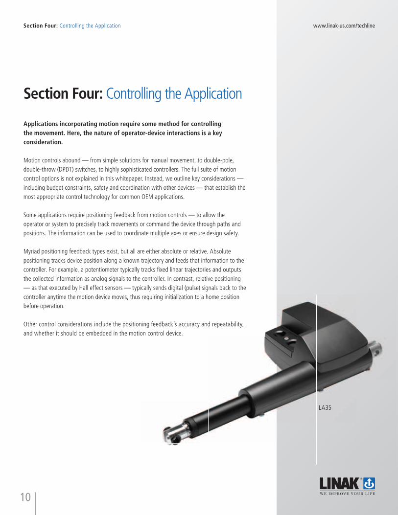
Myriad positioning feedback types exist, but all are either absolute or relative. Absolute positioning tracks device position along a known trajectory and feeds that information to the controller. For example, a potentiometer typically tracks fi xed linear trajectories and outputs the collected information as analog signals to the controller. In contrast, relative positioning — as that executed by Hall effect sensors — typically sends digital (pulse) signals back to the controller anytime the motion device moves, thus requiring initialization to a home position before operation.
Other control considerations include the positioning feedback’s accuracy and repeatability, and whether it should be embedded in the motion control device.
LA35
11
www.linak-us.com/techlineSection Five: Standards and Safety
Section Five: Standards and SafetySome applications must meet safety standards and industry certifications. These requirements depend on the application, the country in which the application will be used, and other considerations. For example, some applications may require evaluation and approval from groups such as Underwriters Laboratory (UL), CSA, ETL and CE.
In regards to functional safety, factors requiring evaluation are the effective protection of the operator and other personnel, as well as the application itself.
Different applications emphasize different aspects of safety but the following are most common:
• Ergonomics – Is the application designed to protect the operator from injury during operation? Injuries can be sustained both when the application is functioning properly and when the application has failed in some manner. Could the application injure someone in a one-time incident, as in a back injury from lifting a heavy load? Could the application injure someone as a result of frequent, repetitive motions over a longer period of time?
• Failure modes – The design should eliminate or mitigate the risk of damage and safety breaches resulting from application or motion device failure. Another consideration is the replacement procedure for various actuator positions, should the motion device happen to fail at each failure mode.
• Environmental issues – Issues related to environmental effects of the application should be considered — including when the motion control device is working properly and in case of failure (as when a hydraulic design leaks).
• Other foreseeable risks – Designers should assess reasonably foreseen dangers resulting from both proper and improper use of the design. Once potential safety risks and hazards are identified, they should be averted with preventive design features.
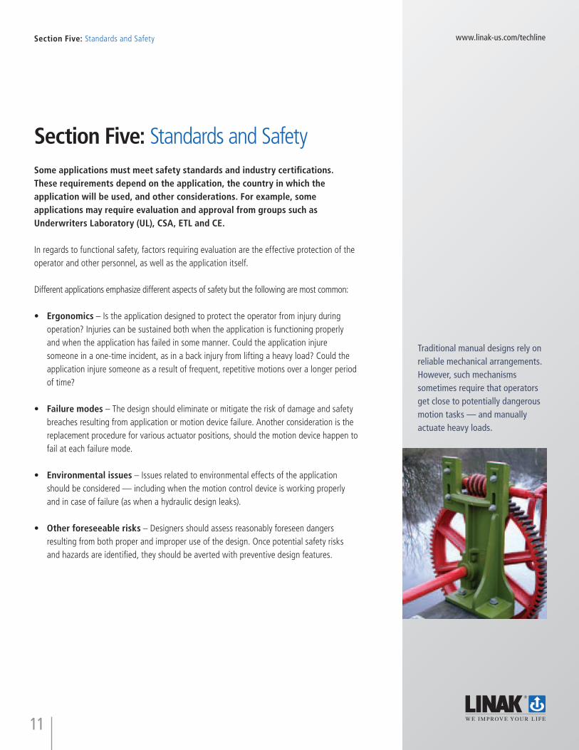
Traditional manual designs rely on reliable mechanical arrangements. However, such mechanisms sometimes require that operators get close to potentially dangerous motion tasks — and manually actuate heavy loads.
12
www.linak-us.com/techlineSection Five: Standards and Safety
When considering motion control devices, the following items can apply:
• Load limiters – Devices to control the maximum load (including clutches, current sensing, pressure sensors and load cells).
• Positioning feedback – Used to confirm proper application positioning and synchronization it with other application operations.
• Backup safety devices – Devices (including gates, emergency shutoffs and safety circuits) that protect operators and machinery in the event of misuse or failure.
• Safety factors – Design the application for forces that do not exceed specified limits.
• Ergonomic evaluation – Includes analysis of all human interaction with the machinery, to anticipate and prevent injuries.
Section Six: Economic FactorsAs mentioned, sometimes the selection of electric linear actuators, hydraulic systems or manual operation can come down to the costs of the solution. In some applications there is simply no capacity to include the costs of anything more than a manually operated system in the design. This section identifi es some of the considerations of the cost of a system:
• System costs – Associated with the motion device, including its controls and subcomponents. Other costs include those associated with inventoried repair parts, multiple vendors or subcomponents sourced from different manufacturers and the amount of space required for the design.
• Installation costs – Associated with the system’s installation, including any temporary loss of production, setup of motion controls, initialization and (in the case of hydraulics) fi lling supply lines with fl uids, priming and confi rming proper system operation with adjustments as needed.
• Design costs – Associated with the costs of engineering software plus analysis executed by engineering personnel tasked with the system design.
• Validation costs – Associated with testing and validating that the solution is appropriate for the intended use with respect to all other considerations (such as temperature, failure modes and lifetime expectations).
• Preventative maintenance costs – Associated with maintenance of the system prior to a system failure.
• Failure costs – Associated with the repair and replacement of the motion control device. Should also include the cost of the downtime due to the failure, as well as those related to its evaluation, where applicable.
• Warranty costs – Associated with the warranty given on the motion control device or system relative to the warranty given for the application.
• Quality costs – Associated with poor quality from suppliers including line rejects, corrective actions, incoming inspections and so on.
• Purchasing costs – Associated with selection and approval of a supplier including site audits, logistic costs, taxes and duties.
• Operating costs – Associated with the energy required to operate the system over a specifi c period of time.
This whitepaper identifi es many considerations useful for evaluating motion-control options, but does not provide an all-inclusive list of design factors. Actual design specifi cations and how they are prioritized vary with the specifi c application at hand. For specifi c questions and design assistance, please contact a LINAK applications engineer at (502) 413-0320 or visit www.linak-us.com/techline.
LINAK is an industry leader in linear actuators and linear motion solutions. The company has a global understanding of various technologies and how they are applied.
LINAK A/S, Guderup, Denmark
LINAK U.S. Inc., Louisville, Kentucky
15
www.linak-us.com/techline
Grain tank coversGrain tank extension and /or open and close the grain tank covers for inspection
BlowerAirfl ow adjustment of blowers
Sieve meshAdjustment of the size of the sieve mesh depending on the crop
ConcaveConcave adjustment depending on the crop
HeaderForward and backwardmovement as well as speed regulation
TrencherEngage and disengage of the trencher unit
LadderAccess ladder extension or retraction, or have an angle on the ladder for easy access
AugerBend the unloading auger in transport situations
OutletWind compensation, changing directions of the outlet i.e. In heavy side wind situations
CutterEngage and disengage the cutter unit
SieveGrain sieve adjustment to keep the sieve in horizontal level when operating in hill areas
Natural ventilationOpen and close the cabin roof
Steering column and driver seatFor easy access and comfort during operation
What the LINAK actuators do for the combine harvester
TECHLINE® actuator systems provide advanced motion control with superior position feedback for a number of different applications
The list of possible actuator solutions to improve ergonomics, comfort and productivity is virtually endless.
16
www.linak-us.com/techline
Terms of useThe user is responsible for determining the suitability of LINAK products for a specific application. LINAK takes great care in providing accurate and up-to-date information on its products. However, due to continuous development in order to improve its products, LINAK products are subject to frequent modifications and changes without prior notice. Therefore, LINAK cannot guarantee the correct and actual status of said information on its products. While LINAK uses its best efforts to fulfil orders, LINAK cannot, for the same reasons as mentioned above, guarantee the availability of any particular product. Therefore, LINAK reserves the right to discontinue the sale of any product displayed on its website or listed in its catalogues or other written material drawn up by LINAK.
All sales are subject to the Standard Terms of Sale and Delivery for LINAK. For a copy hereof, please contact LINAK.
LINAK has a well-developed sales and service organization in Europe, America, Asia and Australia. Therefore, we can assist you and your customers locally, under the global sales concept idea: Be global, act local.
Global presence
For further information, please visit our website:www.linak-us.com/techline
Publ
ishe
d: 0
9.12
.Sal
es_L
itera
ture
/LIN
AK_
eBoo
k
LINAK U.S. Inc.North and South American Headquarters
2200 Stanley Gault Parkway Louisville, Kentucky 40223