1 Electric Motors RSS Technical Lecture 2 Friday, 10 Feb 2012 Prof. Seth Teller RSS I (6.141J / 16.405J) S12 My Research Focus • Perceptive machines alongside people – Integrating experience, models of the environment, and sensor data to plan and carry out useful behaviors • Natural interfaces involving speech gesture • Natural interfaces involving speech, gesture – References to shared surroundings • Fielded robots for real-world utility – Engagement with user communities DARPA Urban Challenge: Self-driving passenger vehicle Agile Robotics for Logistics: Gesture-commandable forklift Voice-commandable autonomous wheelchair
Transcript
1
Electric Motors
RSS Technical Lecture 2
Friday, 10 Feb 2012
Prof. Seth Teller
RSS I (6.141J / 16.405J) S12
My Research Focus• Perceptive machines alongside people
– Integrating experience, models of the environment, and sensor data to plan and carry out useful behaviors
• Current (from datasheet) = ~2 A; Power = I V = 2A * 12V = ~25 W
Interfacing Motor and Microprocessor• So far, we’ve looked only at constant 12V DC• In practice, control motor direction and speed• Accomplished through electronic supportp g pp
– 1. How do we control the motor speed?• PWM handled by PSOC on ORC• Java code provides percent-on of duty cycle
– 2. How do we control motor direction?• Handled by an H-BridgeHandled by an H Bridge
9
PWM: Pulse Width Modulation• Apply motor voltage as a square
wave at fixed frequency (from 60Hz to 50KHz; Orc uses ~16KHz)
• Control motor speed/power by changing the duty cycle (orchanging the duty cycle (or pulse width) of voltage signal– At 0% duty cycle, motor is off– At 100%, full power– At 50%, half power etc.
• Effectively produces a time-averaged voltage signal
• Inductive load of motorth i t i l i ilsmoothes input signal in coils
• Duty cycle: Laptop sends 8-bit value (0..255) to ORC PSOC
Clark and Owings
Sensing speed: Motor Shaft Encoders• Report motor shaft speed (easy) or position (harder)• Codewheel: Circular disk with alternating black
and white regions, mounted on motor shaft
• Optical sensor detects codewheel region transitions
Agilent
• Optical sensor detects codewheel region transitions• Counting the pulses produced in any time interval yields
change in shaft angle (how to compute distance traveled?)• This is basic odometry used for control & “dead reckoning,”
or estimation of position relative to some starting point
10
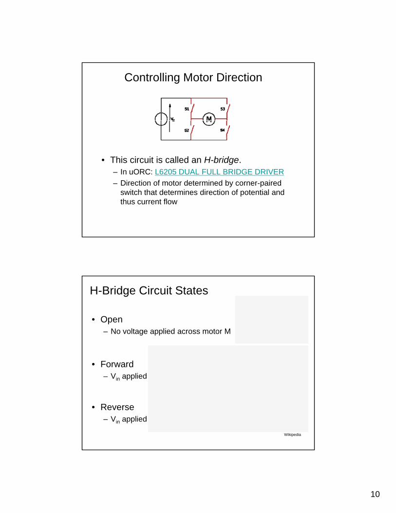
Controlling Motor Direction
• This circuit is called an H-bridge. – In uORC: L6205 DUAL FULL BRIDGE DRIVER
– Direction of motor determined by corner-paired switch that determines direction of potential and thus current flow
H-Bridge Circuit States
• Open– No voltage applied across motor MNo voltage applied across motor M
• Forward– Vin applied left to right across M
• Reverse– Vin applied right to left across M
Wikipedia
11
Servomechanisms (servo motors, servos)• DC motor in an integrated
package with 3 extra elements:– Gearbox between motor
shaft and output shaftshaft and output shaft• Provides low-speed,
high-torque output
– Feedback-based position controlcircuit (pulse-width control)
• Drives servo to commanded “position” (shaft angle)
• Shaft angle sensing (potentiometer)Shaft angle sensing (potentiometer)• Current sense for torque sensing
– Limit stops on output shaft• These mechanically delimit servo’s
minimum & maximum “position”
Stepper Motor (Example: 90-degree bipolar)Rotor: permanentmagnet(s) mountedon output drive shaft
Stator: even N coilsarrayed aroundrotor symmetry axis(out of plane of page)
Clark and Owings• Controller does commutation:Energizes coils in rotationalsequence; rotor swings intoalignment to successive states
• When the coil is kept energized, motor produces “holding torque”
• Adv: holding torque, speed and position control without using encoders or feedback
• Angular resolutions of < 1deg are available!• Brushless!
12
Comparison of Motor Types
Type: Pluses: Minuses: Best For:
DC Motor
Common
Wide variety of sizes
Most powerful
Too fast (needs gearbox)High current (usually)Expensive
Large robots
Most powerful
Easy to interface
Must for large robots
pPWM is complex
Hobby Servo
All in one package
Variety; cheap; easy to mount and interface
Medium power required
Low weight capability
Little speed controlSmall, legged robots
Stepper Precise speed control Heavy for output power Line Motor Great variety
Good indoor robot speed
Cheap, easy to interface
High current
Bulky / harder to mount
Low weight capability, low power
Complex to control
followers, maze solvers
Clark and Owings, p. 29
Supplementary Reading
• Theoretical– Foundations of Electric Power,
J.R. Cogdell
– Electric Motors and their Controls: An Introduction, Tak Kenjo
• Practical– Building Robot Drive Trains,
D Clark and M OwingsD. Clark and M. Owings
– Mobile Robots: Inspiration to Implementation,J.L. Jones, B. Seiger, A.M. Flynn


![Ep118 Lec02 Reflection Refraction[1]](https://static.documents.pub/doc/80x56/563db822550346aa9a90df0d/ep118-lec02-reflection-refraction1.jpg)


