65
ELECTRICAL AND TRAFFIC ENGINEERING MANUAL Section 600 Intelligent Transportation Systems Electrical and ITS Engineering January 2019

ELECTRICAL AND TRAFFIC ENGINEERING MANUAL
Section 600
Intelligent Transportation Systems
Electrical and ITS Engineering
January 2019

TABLE OF CONTENTS
Electrical and ITS Engineering 600 Intelligent Transportation Systems January 2019
Electrical & Traffic Engineering Manual Page i
600 INTELLIGENT TRAFFIC SYSTEMS
601 INTRODUCTION ...................................................................................... 1 601.1 INTRODUCTION .......................................................................... 1 601.2 PURPOSE OF ITS ....................................................................... 1 601.3 ITS ENGINEERING AND REFERENCE DOCUMENTS ............... 1 601.4 TYPES OF ITS SYSTEMS ........................................................... 2 601.5 PLANNING ................................................................................... 2 601.6 ITS PROJECT SCALE .................................................................. 4 601.7 PROJECT PHASING .................................................................... 5 601.8 PROCESS MODEL ...................................................................... 7 601.9 FINANCE ...................................................................................... 8 601.10 INFORMATION MANAGEMENT BRANCH .................................. 8 601.11 DESIGN ........................................................................................ 8 601.12 DOCUMENTATION .................................................................... 10 601.13 DEPLOYMENT ........................................................................... 10 601.14 HANDOVER ............................................................................... 11 601.15 MAINTENANCE ......................................................................... 11
602 ITS COMMUNICATIONS SYSTEMS ..................................................... 12 602.1 GENERAL .................................................................................. 12 602.2 BACKGROUND .......................................................................... 12 602.3 POLICY ...................................................................................... 13 602.4 PLANNING ................................................................................. 14 602.5 DESIGN ...................................................................................... 15
602.5.1 Fibre – General .......................................................................... 15 602.5.2 Fibre – Conduits. ....................................................................... 15 602.5.3 Fibre – Vaults, Boxes and Termination. .................................... 18 602.5.4 Fibre – Cables. .......................................................................... 19 602.5.5 Point-to-Point Wireless. ............................................................. 19 602.5.6 Cellular. ...................................................................................... 20 602.5.7 Dial-up – PSTN. ......................................................................... 22 602.5.8 Satellite. ..................................................................................... 22

TABLE OF CONTENTS
Electrical and ITS Engineering 600 Intelligent Transportation Systems January 2019
Electrical & Traffic Engineering Manual Page ii
602.6 TESTING AND COMMISSIONING ............................................. 23 602.7 DECOMMISSIONING ................................................................. 24
603 ITS POWER ........................................................................................... 25 603.1 GENERAL .................................................................................. 25 603.2 POWER CONSIDERATIONS ..................................................... 25 603.3 SERVICE .................................................................................... 25 603.4 WIRING ...................................................................................... 25 603.5 BACKUP POWER ...................................................................... 25 603.6 ALTERNATIVE POWER SOURCES .......................................... 26
604 ITS SIGNS ............................................................................................. 29 604.1 GENERAL .................................................................................. 29 604.2 POLICY ...................................................................................... 29 604.3 PLANNING ................................................................................. 30 604.4 SIGN NAMING ........................................................................... 30 604.5 DMS DESIGN ............................................................................. 33 604.6 INSTALLATION .......................................................................... 34 604.7 TESTING AND COMMISSIONING ............................................. 34 604.8 DECOMMISSIONING ................................................................. 34
605 CAMERAS ............................................................................................. 36 605.1 GENERAL .................................................................................. 36 605.2 BACKGROUND .......................................................................... 36 605.3 POLICY ...................................................................................... 37 605.4 SITE SELECTION ...................................................................... 37 605.5 DESIGN ...................................................................................... 38 605.6 INSTALLATION .......................................................................... 40 605.7 TESTING AND COMMISSIONING ............................................. 40 605.8 ACCEPTANCE ........................................................................... 41 605.9 MAINTENANCE ......................................................................... 41 605.10 DECOMMISSIONING ................................................................. 41
606 SENSORS ............................................................................................. 42 606.1 GENERAL .................................................................................. 42 606.2 BACKGROUND .......................................................................... 42 606.3 INDUCTIVE DETECTOR LOOP ................................................. 42 606.4 RADAR DETECTION ................................................................. 43 606.5 VIDEO DETECTION ................................................................... 44 606.6 PROBE BASED SAMPLING ....................................................... 44 606.7 ENVIRONMENTAL SENSORS .................................................. 45
606.7.2 Weather Sensors ....................................................................... 45 606.7.3 Road Surface ............................................................................. 46

TABLE OF CONTENTS
Electrical and ITS Engineering 600 Intelligent Transportation Systems January 2019
Electrical & Traffic Engineering Manual Page iii
606.7.4 Ambient Light ............................................................................. 46 606.8 DESIGN ...................................................................................... 46 606.9 INSTALLATION .......................................................................... 47 606.10 TESTING AND COMMISSIONING ............................................. 47 606.11 DECOMMISSIONING ................................................................. 47
607 ADVANCED TRAVELLER INFORMATION SYSTEMS ......................... 48 607.1 GENERAL .................................................................................. 48 607.2 BACKGROUND .......................................................................... 48 607.3 POLICY ...................................................................................... 48 607.4 PLANNING ................................................................................. 48 607.5 DESIGN ...................................................................................... 49 607.6 INSTALLATION .......................................................................... 49 607.7 TESTING, CALIBRATION AND COMMISSIONING .................... 49 607.8 MAINTENANCE ......................................................................... 50 607.9 DECOMMISSIONING ................................................................. 50
608 REVERSIBLE LANE CONTROL SYSTEMS ......................................... 51 608.1 GENERAL .................................................................................. 51 608.2 BACKGROUND .......................................................................... 51 608.3 PLANNING AND DESIGN .......................................................... 51 608.4 DOCUMENTATION .................................................................... 52 608.5 TESTING AND COMMISSIONING ............................................. 52 608.6 MAINTAINANCE ........................................................................ 53 608.7 DECOMMISSIONING ................................................................. 53
609 MAINTENANCE ..................................................................................... 54 609.1 GENERAL .................................................................................. 54 609.2 MAINTENANCE SPECIFICATIONS ........................................... 54 609.3 ENCLOSURES AND CABINETS ................................................ 54 609.4 ALTERNATIVE POWER SOURCES .......................................... 55 609.5 ELECTRONIC SIGNS ................................................................ 56 609.6 CAMERAS .................................................................................. 56 609.7 SENSORS .................................................................................. 56
610 PRIVACY AND SECURITY.................................................................... 58 610.1 GENERAL .................................................................................. 58 610.2 PRIVACY .................................................................................... 58 610.3 SECURITY ................................................................................. 58

TABLE OF CONTENTS
Electrical and ITS Engineering 600 Intelligent Transportation Systems January 2019
Electrical & Traffic Engineering Manual Page iv
LIST OF TABLES Table 1. ITS Project Scale (Courtesy of PBX Engineering ............................................... 4 Table 2. ITS Project Scale (Courtesy of PBX Engineering).............................................. 6 Table 3. Cellular Signal Strength Guide......................................................................... 21 Table 4. Fibre Attenuation Limits ................................................................................... 23 Table 5. ITS Sign Functions and Abbreviations ............................................................. 31 Table 6. DMS and Warning Sign Naming Example ....................................................... 32
LIST OF FIGURES
Figure 1. V-Model and Ministry Phases ........................................................................... 7 Figure 2. Typical Fibre Optic Conduit Crossing ............................................................. 17 Figure 3. ITS Sign Naming Example ............................................................................. 32
LIST OF APPENDICES 600.1 Camera Warrant 600.2 Camera Installation and Field Check List 600.3 Local Area Specification Example 600.4 Maintenance Check Sheet Example 600.5 Decommissioning Process 600.6 Example Fibre Test Report 600.7 ITS Project Check List 600.8 Maintenance Specification Example
Electronic versions of this manual and appendices available at: http://www.th.gov.bc.ca/publications/eng_publications/electrical/electrical_and_traffic_eng/Electrical_Signing_Design_Manual/tableofcontents.htm

Electrical and ITS Engineering 600 Intelligent Transportation Systems January 2019
Electrical & Traffic Engineering Manual Page 1
601 INTRODUCTION
601.1 INTRODUCTION .1 Section 600 provides guidelines, information, and polices for various
Intelligent Transportation Systems (ITS) elements currently in use or contemplated by the ministry.
.2 Section 600 provides design requirements for ministry ITS projects, but is generally a guidance document. ITS Engineering is relatively new and changes continually as standards and technologies continue to evolve.
.3 Engineering judgement is heavily used in the planning and design of ITS projects. Engineering judgement in the transportation industry is defined as “the evaluation of available pertinent information, and the application of appropriate principles, provisions, and practices as contained in [publications], for the purpose of deciding upon the applicability, design, operation, or installation of a traffic control device. Engineering judgment shall be exercised by an engineer, or by an individual working under the supervision of an engineer, through the application of procedures and criteria established by the engineer. Documentation of engineering judgment is not required.” (FHWA MUTCD 2009 Section 1A.13.03.64).
601.2 PURPOSE OF ITS .1 ITS Canada defines “Intelligent Transportation Systems (ITS) as the
application of advanced and emerging technologies (computers, sensors, control, communications, and electronic devices) in transportation to save lives, time, money, energy and the environment” (www.itscanada.ca).
.2 The need for improved transportation and commercial vehicle safety, operation, and efficiencies are important to the ministry; ITS can provide cost effective means to this end.
601.3 ITS ENGINEERING AND REFERENCE DOCUMENTS .1 ITS share many elements of electrical, electronic, and information
technology. The following manuals and documents are referred in this section:
Ministry Electrical and Traffic Engineering Manual – Section 400/500 Ministry Web Camera Installation and Maintenance Manual Rev 1.1 Ministry Principles for Sharing, Swapping, and Co-building Fibre
Optic Infrastructure (October 2017) Previous ministry ITS studies and reports

601 INTRODUCTION
Electrical and ITS Engineering 600 Intelligent Transportation Systems January 2019
Electrical & Traffic Engineering Manual Page 2
Manual on Uniform Traffic Control Devices (MUTCD) Canadian Electrical Code (CEC) US DOT Federal Highway Administration (FHWA) Telecommunications Industry Association (TIA) Standards
601.4 TYPES OF ITS SYSTEMS .1 ITS can be deployed similar to traditional traffic control signs, such that it
provides information for motorists to use in real-time. ITS can be divided in the following categories:
.2 Regulatory ITS Systems. Regulatory ITS systems notify motorists of traffic regulations using signals, displays and signs. The motorist is expected to follow the direction from the ITS System. Disregarding the ITS signals, displays, or signs constitutes a legal offense. Legislation providing authorization for the ITS signals, displays or signs may be found in the Motor Vehicle Act. Example: The lane signals at a tunnel or bridge is considered regulatory because drivers must follow the signals.
.3 Advisory ITS Systems. Advisory ITS Systems call attention to potentially hazardous or dangerous conditions using displays or signs. The motorist is expected to adjust their driving behaviour upon receiving advice from the ITS System displays or signs. Example: Severe Weather Conditions Signs (SWCS), advises drivers that the road conditions have changed due to weather, and they should pay additional attention to the road, and alter their driving behaviour to account for the conditions.
.4 Informational ITS Systems. Informational ITS Systems can provide route, travel time or other information to the motorist. The motorist can choose to adjust their route or expectations based on the information from the sign. Example: Advanced Travelers Information Systems (ATIS) can provide approximate travel times, allowing motorists to decide their route ahead of time.
601.5 PLANNING .1 Planning is a critical element in to any ITS program. ITS should be planned
on an area basis, keeping in mind the needs, defined vision, and strategic plan of the ministry.
.2 Pilots are often deployed prior to a wide scale deployment. A before and after analysis of a pilot should be conducted to determine its efficacy.
.3 In 2013 the British Columbia’s Provincial ITS Vision and Strategic Plan was updated. The strategic plan presents a blueprint for the deployment of multi-modal, multi-jurisdictional ITS throughout the Province of British Columbia. This Vision and Strategic Plan is road map followed by the ministry with

601 INTRODUCTION
Electrical and ITS Engineering 600 Intelligent Transportation Systems January 2019
Electrical & Traffic Engineering Manual Page 3
respect to ITS planning. A copy of the plan can be obtained by contacting ministry Electrical and ITS Engineering.
.4 In 2009 Transport Canada developed the “Regional ITS Architecture Guidance for Canada: Developing, Using and Maintaining an ITS Architecture For Your Region”. This is a guide for transportation professionals who are involved in the development, use, or maintenance of regional ITS architectures. The document describes a process for creating a regional ITS architecture with supporting examples of each architecture product. This document is used by the ministry in conjunction with their Vision and Strategic Plan, and the TransLink Regional Telecommunications and Infrastructure Plan (RTIP).
601 INTRODUCTION
Electrical and ITS Engineering 600 Intelligent Transportation Systems January 2019
Electrical & Traffic Engineering Manual Page 4
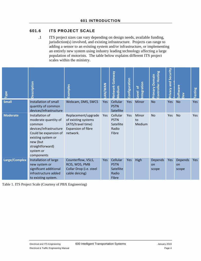
601.6 ITS PROJECT SCALE .1 ITS project sizes can vary depending on design needs, available funding,
jurisdiction(s) involved, and existing infrastructure. Projects can range to adding a sensor to an existing system and/or infrastructure, or implementing an entirely new system using industry leading technology affecting a large population of motorists. The table below explains different ITS project scales within the ministry.
Type
Desc
riptio
n
Exam
ples
LAN
/WAN
Net
wor
k G
atew
ay
Med
ium
Conf
igur
atio
n
Leve
l of
In
tegr
atio
n
Prim
ary
Dom
ain
Cont
rolle
r Hos
ting
Priv
acy
and
Secu
rity
Asse
ssm
ent
Soft
war
e De
v
Test
ing
Small Installation of small quantity of common devices/infrastructure
Webcam, DMS, SWCS Yes Cellular PSTN Satellite
Yes Minor No Yes No Yes
Moderate Installation of moderate quantity of common devices/infrastructure Could be expansion of existing system or new (but straightforward) system or components
Replacement/upgrade of existing systems (ATIS/travel time) Expansion of fibre network.
Yes Cellular PSTN Satellite Radio Fibre
Yes Minor to Medium
No Yes No Yes
Large/Complex Installation of large new system or significant additional infrastructure added to existing system.
Counterflow, VSLS, RCIS, WDS, PMB Collar Drop (i.e. steel cable deicing)
Yes Cellular PSTN Satellite Radio Fibre
Yes High Depends on scope
Yes Depends on scope
Yes
Table 1. ITS Project Scale (Courtesy of PBX Engineering)
601 INTRODUCTION
Electrical and ITS Engineering 600 Intelligent Transportation Systems January 2019
Electrical & Traffic Engineering Manual Page 5
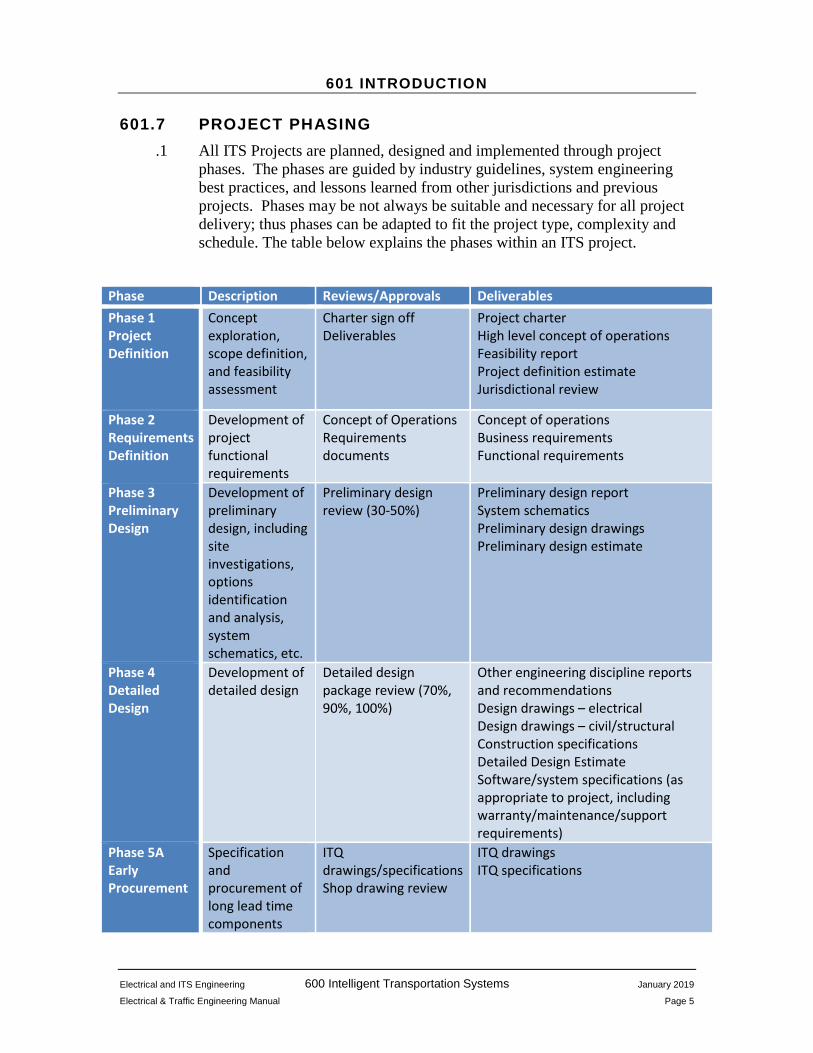
601.7 PROJECT PHASING .1 All ITS Projects are planned, designed and implemented through project
phases. The phases are guided by industry guidelines, system engineering best practices, and lessons learned from other jurisdictions and previous projects. Phases may be not always be suitable and necessary for all project delivery; thus phases can be adapted to fit the project type, complexity and schedule. The table below explains the phases within an ITS project.
Phase Description Reviews/Approvals Deliverables Phase 1 Project Definition
Concept exploration, scope definition, and feasibility assessment
Charter sign off Deliverables
Project charter High level concept of operations Feasibility report Project definition estimate Jurisdictional review
Phase 2 Requirements Definition
Development of project functional requirements
Concept of Operations Requirements documents
Concept of operations Business requirements Functional requirements
Phase 3 Preliminary Design
Development of preliminary design, including site investigations, options identification and analysis, system schematics, etc.
Preliminary design review (30-50%)
Preliminary design report System schematics Preliminary design drawings Preliminary design estimate
Phase 4 Detailed Design
Development of detailed design
Detailed design package review (70%, 90%, 100%)
Other engineering discipline reports and recommendations Design drawings – electrical Design drawings – civil/structural Construction specifications Detailed Design Estimate Software/system specifications (as appropriate to project, including warranty/maintenance/support requirements)
Phase 5A Early Procurement
Specification and procurement of long lead time components
ITQ drawings/specifications Shop drawing review
ITQ drawings ITQ specifications

601 INTRODUCTION
Electrical and ITS Engineering 600 Intelligent Transportation Systems January 2019
Electrical & Traffic Engineering Manual Page 6
Phase 5B Construction
Supply and installation of equipment; testing as appropriate to scope
Field inspections Software deployment planning Test plan review Test plan approval
Test plans Inspection reports
Phase 6 Integration, Testing and Calibration
As appropriate to the project, configure and test software/system components through various levels of testing
Traceability matrix Test plans (SAT/SIT/FAT/UAT)
Traceability matrix Test plans (Factory, Field, System, User)
Phase 7 Operations & Maintenance
Operations and maintenance of system, including asset lifecycle management.
Training plans Maintenance requirements
Training plans Training Operations manuals Maintenance manuals Preventive/corrective maintenance procedures
Table 2. ITS Project Scale (Courtesy of PBX Engineering)
601 INTRODUCTION
Electrical and ITS Engineering 600 Intelligent Transportation Systems January 2019
Electrical & Traffic Engineering Manual Page 7
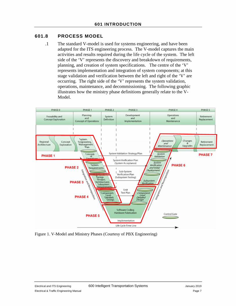
601.8 PROCESS MODEL .1 The standard V-model is used for systems engineering, and have been
adapted for the ITS engineering process. The V-model captures the main activities and results required during the life cycle of the system. The left side of the ‘V’ represents the discovery and breakdown of requirements, planning, and creation of system specifications. The centre of the ‘V’ represents implementation and integration of system components; at this stage validation and verification between the left and right of the ‘V’ are occurring. The right side of the ‘V’ represents the system validation, operations, maintenance, and decommissioning. The following graphic illustrates how the ministry phase definitions generally relate to the V-Model.
Figure 1. V-Model and Ministry Phases (Courtesy of PBX Engineering)

601 INTRODUCTION
Electrical and ITS Engineering 600 Intelligent Transportation Systems January 2019
Electrical & Traffic Engineering Manual Page 8
601.9 FINANCE .1 ITS project funding can come as part of a larger capital project
announcement. The project will typically come with a defined scope, funding, and timeframe.
.1 Business units can seek funding from the Capital Program Board (CPB) for large ITS projects over $1 million. A project proposal package is required for CPB review and consideration.
.2 ITS Programs can submit proposals to the CPB for smaller and pilot projects with ITS components. ITS Programs assists with pilots with seed money and expertise before engaging in a larger scope.
601.10 INFORMATION MANAGEMENT BRANCH .1 The ministry Information Management Branch (IMB) provides information
technology direction, guidance, and support. Modern ITS technology has high data and network requirements. IMB should be included for ITS projects as team members, as they are the subject matter experts for software application development, cybersecurity, data architecture, and network security.
.1 Software used and developed for the ITS applications must follow IMB’s guidance regarding Software Development Lifecycle (SDLC). As a general guidance for project teams, SDLCs must also take into account of the physical infrastructure of ITS equipment on roadways, and transportation industry standards/practices.
601.11 DESIGN .1 Specific design considerations for systems and components are discussed in
detail in subsequent chapters. General considerations for ITS include:
Traffic: Traffic Engineering should identify the ultimate intent of the system and what the intended impacts are for the users of the transportation systems. Traffic benefits and risks should be weighed to help guide the design requirements.
Electrical: Electrical and ITS Engineering should identify the feasibility and level of resources required to implement ITS infrastructure on the roadway. Electrical and ITS Engineering must identify power, communication, and integration challenges.
Resource sharing: When possible, ITS projects should maximize existing infrastructure (i.e. structure, power, and communication) to save on cost. In addition, ITS projects should reach out to other

601 INTRODUCTION
Electrical and ITS Engineering 600 Intelligent Transportation Systems January 2019
Electrical & Traffic Engineering Manual Page 9
program areas to ensure that ministry infrastructure usage is maximized.
Jurisdictional Reviews and Industry Standard: For new ITS projects piloted by the ministry, a jurisdictional review and study of current industry standards should be conducted. Jurisdictional reviews allow the ministry to capture lessons learned from other organizations, providing additional background for design decisions.
Future Expandability: When piloting new ITS projects and technologies, the design should consider if the project can be expanded to other locations and additional features. It is important to have strategic input and vision to ensure that piloted systems with a potential to expand will have the correct hardware and software for the future. Systems that are considered standalone must be documented thoroughly for future reference.
Data: ITS can generate a large amount of data. The data can be used for real-time applications, or archived for future studies. Data structure, security, archival period, and sharing must be thoroughly discussed during the first phases of design. IMB shall be consulted whenever data is created or consumed by ITS.
Network: Modern ITS have been shaped greatly from the improvements in networking. Networking design considerations should include bandwidth, data consumption, security, and expandability of network. IMB shall be consulted whenever networking is involved.
Software Design Cycle: ITS projects that have a software component should have a design process that is in alignment with the ‘V’ design process (see 601.7 and Table 2). Design considerations for software would include cybersecurity, privacy, hosting location, and redundancy. Patch and update procedures would also be analyzed, based on engineering risk assessments. IMB shall be consulted whenever software is designed or procured.
Maintenance: The maintainability of system and components must be considered during the design phases. The system must be maintainable for operations after the project is complete. Considerations such as vendor support, ease of procuring replacement components, access to infrastructure for maintenance, extended warranty, etc. must all be considered in the design phase. For new systems and field components, training and maintenance documents are required.
Lifespan and Renewal: Closely related to maintenance, the lifespan of the system and components should be considered in the design phase. All components will have an estimated lifetime, and it is important to plan for when the system will likely need a complete renewal to avoid
601 INTRODUCTION
Electrical and ITS Engineering 600 Intelligent Transportation Systems January 2019
Electrical & Traffic Engineering Manual Page 10
unplanned system failures, which are often expensive and frustrating to fix.
601.12 DOCUMENTATION .1 All drawings shall follow the drafting standards listed in Section 700 of the
Electrical and Traffic Engineering Manual. The ministry has specific information and details which will need to be presented on drawings. See Appendix 700 for examples of ITS designs.
.1 Finalized documentation from the consultant or designer must include:
As-built drawings; Network settings (if applicable); System Manuals; and Test/Commissioning reports.
Additional documentation may be required depending on size and complexity of system.
601.13 DEPLOYMENT .1 The deployment is typically undertaken by the consultant or designers with
guidance from the ministry. Depending on the scope and size of the project, deployment typically involves elements such as engineering (preparing plans, specifications, and estimates), project management, software selection or design, equipment specification, and selection, equipment set-up, testing and commissioning, documentation and training.

601 INTRODUCTION
Electrical and ITS Engineering 600 Intelligent Transportation Systems January 2019
Electrical & Traffic Engineering Manual Page 11
601.14 HANDOVER .1 After the project is commissioned, a handover process will be conducted.
Electrical and ITS Engineering will review, and file finalized record drawings and documentation. Ministry ITS Operations and maintenance contractors may conduct site visits and receive technical training for new equipment and systems.
.2 Ministry ITS Operations, under the guidance of Electrical and ITS Engineering, will coordinate operational and maintenance issues as they arise. ITS Operations acts as the stewards of all ITS systems and their components. They provide support and operational guidance for Regions, Districts and maintenance contractors.
601.15 MAINTENANCE .1 Typically, ITS projects are maintained by the electrical maintenance
contractor. New ITS projects may require additional training for the maintenance contractor. The project manager should include training and maintenance documentation as part of the project. Chapter 609 will discuss maintenance in further detail.
.2 Examples of maintenance documents are found in Appendix 600.
.3 Maintenance contractors can contact ministry ITS Operations for guidance once systems are in operation.

Electrical and ITS Engineering 600 Intelligent Transportation Systems January 2019
Electrical & Traffic Engineering Manual Page 12
602 ITS COMMUNICATIONS SYSTEMS
602.1 GENERAL .1 This chapter describes communication methods used by ministry ITS
systems. Communication systems provide the medium to exchange data between field devices, software, and the user. Network design is not discussed in this chapter. Consult with ministry Information Management Branch (IMB) regarding network designs.
602.2 BACKGROUND .1 Data communications between field devices and processing units is a key
component in ITS systems. Data communications may be local to the system or to a remote central server where data may be analyzed, displayed, archived, and/or input into systems to affect output or be evaluated for decisions.
.2 From an electronic perspective, communication systems can as simple as a single wire conductor, an RF link, or as complicated as fibre optic network spanning across the country. A communication system should be carefully selected to ensure it is appropriate for the task.
.3 Communication systems can be broken down into the physical medium and protocol.
The physical medium describes the conduit for the signal: is how the data travels. Examples of physical medium can include fibre optic, copper conductors, and/or radio frequency (RF) signals. A communication system network can consist of a single or multiple physical mediums.
The protocol are the rules communicating devices must follow in order to complete a successful data exchange. Standard protocols for transportation related ITS devices include National Transportation Communications for ITS Protocol (NTCIP) and for general networking protocols include Transmission Control Protocol/Internet Protocol (TCP/IP) and Secure Shell (SSH).
.4 Ministry ITS devices are used across the province in both urban and rural areas. Communication to these devices varies as it is dependent on the availability of choices.
Device on Internet. The device communicates through the internet. Both device and processing system have internet connections for communication. The internet service provider at the device level can vary depending on the availability at the location.

602 ITS COMMUNICATIONS SYSTEMS
Electrical and ITS Engineering 600 Intelligent Transportation Systems January 2019
Electrical & Traffic Engineering Manual Page 13
Device on Private Network. The field device communicates through a private network. The field device and processing system reside on thesame network for direct communication. Traditionally, private networks have been constricted to a small geographic location. However, as fibre optics is continually added to ministry infrastructure, wide area private networks are becoming more common. It should be noted that ministry ITS on fibre optic networks may use other protocols than TCP/IP.
Device on Direct Connections. The field device does not have internet access and is communicated to on an as-and-when basis. Examples of such connections include PSTN and direct serial (RS232/485).
602.3 POLICY .1 Any roadwork in urban areas that meets all the following criteria must
include fibre communication conduit for ITS purposes. Any Provincial Numbered Roadway or Provincial Major Road
Network, overpass, bridge or tunnel that does not already have fibre communication conduit;
Any project that has an estimated construction cost of greater than $250,000; and
Any project within the Metro Vancouver limits, including Highway 99 to Whistler and Highway 1 to Chilliwack OR any urban population in the province greater than 75,000.
.2 Any roadwork in rural areas that meets all the following criteria must include fibre communication conduit for ITS purposes:
Any Provincial Numbered Roadway or Provincial Major Road Network overpass, bridge or tunnel that does not already have fibre communication conduit.
.3 The most practical and cost-effective means should be used for ITS communications. An engineering assessment may be required to determine the most suitable method.
.4 As a general guideline, the order of preference for communication systems is as follows:
Ministry Owned Fibre. A fibre optic network built and owned by the ministry. The ministry owned fibre network should be the first choice as it provides high bandwidth, unlimited volume, and has no fees.
Shared/Leased Fibre. A fibre optic network shared or leased between jurisdictions that provides high bandwidth and typically unlimited data usage. Coordination between jurisdictions for connection and changes may be required.

602 ITS COMMUNICATIONS SYSTEMS
Electrical and ITS Engineering 600 Intelligent Transportation Systems January 2019
Electrical & Traffic Engineering Manual Page 14
Managed Service. Network and IT services outsourced to a third party dedicated to supporting all aspects of network and data communications. This is typically reserved for high bandwidth and high reliability applications and requires an annual or monthly fee.
Point-to-Point Wireless. Wireless nodes may provide a solution when a physical connection is not practical or cost effective.
Cellular Internet Connection. Internet access can be provided to isolated or standalone ITS devices. Generally, there are data bandwidth and volume restrictions and a monthly fee is typically required.
Dial-up Connection. In areas where wireless services are not available, dial-up (also called land-line or Public Switched Telephone Network (PSTN)) can be used to access standalone ITS devices. This method is generally reserved for low bandwidth, low volume applications that are self-sufficient and require little remote maintenance or configuration. Typically, a monthly fee is required.
Satellite Connection. Internet access can be provided to isolated or standalone ITS devices where no other means of communications exist. Applications should be self-sufficient and require little remote maintenance or configuration. Typically, monthly fee is required which may be reduced by committing to a multi-year plan.
.5 IMB shall be consulted on all new communications systems types. IMB will provide further guidance regarding communication equipment procurement and security.
.6 The ministry document Principles for Sharing, Swapping, and Co-building Fibre Optic Infrastructure (October 2017) describes various scenarios in which the ministry share, swaps, and co-builds fibre optic telecommunications infrastructure, and provides specific guiding principles for different scenarios.
602.4 PLANNING .1 ITS strategies and guiding documents should be consulted with ITS
Engineering prior to the planning phase. The Regional Telecom Infrastructure Plan is an example of a document that provides strategies and guidance for a future state system between different jurisdictions.
.2 The planning of ITS communications should capitalize on existing infrastructure when possible by using existing communication systems for new ITS devices.
.3 Careful analysis of communication availability, bandwidth, estimated data usage, cost, security, and effect on existing systems should be considered prior to design.
602 ITS COMMUNICATIONS SYSTEMS
Electrical and ITS Engineering 600 Intelligent Transportation Systems January 2019
Electrical & Traffic Engineering Manual Page 15
Communication Availability. In an urban environment it is possible that any of the communication systems noted above may be available. In a rural environment the communication options may be limited and an analysis should be completed to determine which option, if any, is suitable for the application.
Bandwidth. The bandwidth for the application should be approximated at the planning stage. Applications involving live streaming video, and/or high capacity data packets will likely require high bandwidth.
Estimated Data Usage. Applications that require continual data transmission will communicate high data volume. Using Internet based communication through an ISP may result in higher subscription costs.
Cost. Cost can be generalized into two categories: capital and operational. A cost-benefit analysis should be completed for ITS devices that require high levels of bandwidth and data usage. In many cases, it may be beneficial to invest a higher capital cost for a private network connection, rather than paying operational costs that could increase over time.
Security. Security must be given high priority in the selection of communication systems. The system must be sufficiently secure to protect data and ITS device from intrusion. IMB shall be consulted in all matters relating to cyber security.
Effect on Existing Systems. If communication systems are to be shared careful analysis should be completed to ensure that new ITS devices do not compromise or diminish the performance of the system.
602.5 DESIGN
602.5.1 Fibre – General .1 New fibre infrastructure may vary depending on the application. The design
should take into consideration several factors, including difficulty of installation, construction costs and also provisions for future expandability and upgrades. The design should consider whether the conduits and cables are for backbone or distribution. At the discretion of the designer and in consultation with ministry Electrical and ITS Engineering, the guidelines below may be modified to meet requirements.
602.5.2 Fibre – Conduits. .1 Where communication ducting is required, HDPE or RPVC conduits shall be
provided on the main highway and cross streets. The number of

602 ITS COMMUNICATIONS SYSTEMS
Electrical and ITS Engineering 600 Intelligent Transportation Systems January 2019
Electrical & Traffic Engineering Manual Page 16
communication and power conduits in the common trench shall be determined by the highway classification.
Major Urban Highway (6 lanes or more): .1 4 – 32mm or 50mm communication conduits; and .2 1 – 50mm ITS power conduit (use RVPC only).
Major Highway (4 lanes or less): .1 2 – 32mm or 50mm communication conduits; and .2 1 – 50mm ITS power conduit (use RVPC only).
.2 Conduit road crossings shall be provided where ITS equipment is planned such as strategic locations, intersections and interchanges. Conduit road crossings shall include a minimum of 1-50mm for ITS power and 2 – 32mm or 50mm for ITS communications. See Figure 2 below for fibre optic conduit crossings.

602 ITS COMMUNICATIONS SYSTEMS
Electrical and ITS Engineering 600 Intelligent Transportation Systems January 2019
Electrical & Traffic Engineering Manual Page 17
Figure 2. Typical Fibre Optic Conduit Crossing
.3 Conduit, excavation, backfill, etc. shall meet all ministry requirements. See
Standard Specifications for Highway Construction for details. .4 Where conduit crosses bridge and overpass structures it shall be:
RPVC cast into the parapet or, Galvanized Rigid Metal Conduit (RMC) surface mounted on the
structure. Surface mount the conduit and the supports shall be reviewed by a structural engineer registered with the EGBC. Fibreglass Reinforced Epoxy (FRE™) may also be considered for surface mount where weight is an issue. In areas where the FRE is being used extra heavy wall FRE shall be considered to reduce the

602 ITS COMMUNICATIONS SYSTEMS
Electrical and ITS Engineering 600 Intelligent Transportation Systems January 2019
Electrical & Traffic Engineering Manual Page 18
potential for mechanical damage and vandalism. Support spacing shall meet Canadian Electrical Code requirements.
The conduit shall be designed to accommodate differential soil settlements of the bridge structure.
Conduits shall be designed with expansion fittings to accommodate expansion and contraction of the conduit and bridge structure. Conduit manufacturers typically provide information regarding conduit expansion and contraction and the bridge design engineer can provide information with respect to expansion and deflection on the bridge structure.
See Figure 2 for a typical bridge and tunnel crossing. Unused ducts shall be capped and plugged. The contractor shall verify
the ducting is free of obstruction without breaks or damage. It is recommended the project contractor check pull strings by pulling at both ends. If cable jetting is proposed the contractor should use a cable jetting system to install pull strings under the witness of the ministry representative.
602.5.3 Fibre – Vaults, Boxes and Termination.
.1 Small concrete vaults shall be installed at appropriate intervals based on the scope of the design and consideration for future expansion. Considerations for expansion should include whether the fibre is to function as a backbone or a distribution network. Spacing for vaults is typically up to 600m; vault spacing shall be determined by the designer in consultation with ministry Electrical and ITS Engineering.
.2 All vaults and box lids shall be labelled “COMM”.
.3 Concrete vaults shall be ministry approved.
.4 Vaults shall be sized appropriately to accommodate cable slack and splice cases. Individual cables and splice cases should be freely accessible and removable without impediment from other cables and splice cases.
.5 Conduit entry and exit orientation should be consistent throughout the installation.
.6 Concrete vaults on bridge structures should be avoided. If it is not possible to avoid they shall be a suitably sized aluminum product with a grey powder coat finish and NEMA 3R rating.
.7 Vaults shall be secured against unauthorized access and vandalism.

602 ITS COMMUNICATIONS SYSTEMS
Electrical and ITS Engineering 600 Intelligent Transportation Systems January 2019
Electrical & Traffic Engineering Manual Page 19
602.5.4 Fibre – Cables.
.1 All fibre colour coding shall conform to current TIA-598 and IEC 60304 standards.
.2 Fibre optic cables come in two basic types, single mode and multimode:
Single Mode (SM) fibres have a small glass core, approximately 9-10μm in diameter. They are identified with a yellow coloured outer sheath. SM fibres are used for high speed data transmission over long distances. They are less susceptible to attenuation than multimode fibres, with an attenuation rate of 0.2 to 0.4 dB/km. SM fibres shall conform to ITU-T G.652 (IEC 60793 OS1) or G.652D (IEC 60793 OS2). Other SM fibres may be used for special applications.
Multimode (MM) fibres have large cores, typically 50, 62.5, 80 and 100μm. They are identified with an orange or aqua coloured outer sheath. Because of the higher attenuation rate of 1 to 6 dB/km, they are best for shorter distances, such as inside buildings.
.3 All fibre runs shall use SM fibre.
.4 The fibre cable size shall be determined by the highway classification. Major Urban Highway (6 lanes or more) – 144C per conduit. Major Highway (4 lanes or less) – 48C per conduit. Minor Roadways or Lateral crossings – 12C per conduit.
.5 All permanent fibre splices shall be fused. Fuses shall not have attenuation greater than 0.1dB.
.6 Designers shall provide signal loss calculations for each continuous segment of fibre optic cable between patch panel and terminations.
.7 The ministry currently has no written specifications for fibre cable and splice box assemblies. The designer shall document the product(s) and all technical and performance specifications and have their use approved by ministry Electrical and ITS Engineering.
.8 Patch panels shall be sized to allow for future expansion and cabling shall be clearly labelled.
602.5.5 Point-to-Point Wireless. .1 Point-to-point wireless should only be used when hardwired networks are
impracticable or costly.

602 ITS COMMUNICATIONS SYSTEMS
Electrical and ITS Engineering 600 Intelligent Transportation Systems January 2019
Electrical & Traffic Engineering Manual Page 20
.2 Frequency hopping spread spectrum radios operating in the 900MHz, 2.4GHz, and 5.9GHz band are readily available, do not require a license, and integrate easily into TCP/IP based networks.
.3 Wireless devices must comply with ministry networking security requirements. Consult IMB for further information.
602.5.6 Cellular.
.1 When cellular communication is used signal strength must be evaluated.
Cellular service in urban areas is typically good. The effect of manmade structures must be considered as they can attenuate signal strength.
Cellular service in rural areas reception is not consistent across the Province. Natural obstructions can create dead zones. Seasonal topographical changes, such as snow or changes in vegetation density can also affect signal propagation. The location of the nearest cellular tower should be noted for directional antenna usage (see 602.6.4.2 below).
.2 When testing a site for signal strength and quality, the modem and antenna specified for the design should be used to ensure the designed performance is consistent with the operational performance.
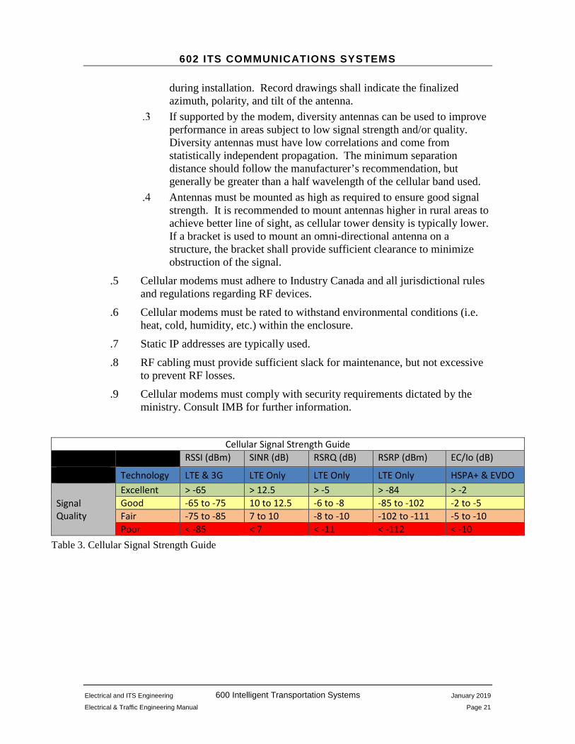
.3 The ministry does not have a standard for minimum signal strength for cellular modems. The requirements of the ITS device may vary and it may be that a lower data rate due to weaker signal may suffice for one application, but not another. Generally, the device should not be subject to outages due to poor cellular receptions. Refer to Table 1 Cellular Signal Strength Guide below for a summary of signal strengths for various cellular technologies.
.4 Designers can select omni-directional or directional antennas. Omni-directional antennas shall be the norm for any site that has good cellular reception.
Omni-directional antennas that specify the requirement for a physical ground plane shall include one.
Directional antennas shall only be used when there is significant improvement over omni-directional antennas. Design drawings shall specify the azimuth and polarity of directional antennas. Final adjustments to ensure the best signal possible shall be conducted
602 ITS COMMUNICATIONS SYSTEMS
Electrical and ITS Engineering 600 Intelligent Transportation Systems January 2019
Electrical & Traffic Engineering Manual Page 21
during installation. Record drawings shall indicate the finalized azimuth, polarity, and tilt of the antenna.
If supported by the modem, diversity antennas can be used to improve performance in areas subject to low signal strength and/or quality. Diversity antennas must have low correlations and come from statistically independent propagation. The minimum separation distance should follow the manufacturer’s recommendation, but generally be greater than a half wavelength of the cellular band used.
Antennas must be mounted as high as required to ensure good signal strength. It is recommended to mount antennas higher in rural areas to achieve better line of sight, as cellular tower density is typically lower. If a bracket is used to mount an omni-directional antenna on a structure, the bracket shall provide sufficient clearance to minimize obstruction of the signal.
.5 Cellular modems must adhere to Industry Canada and all jurisdictional rules and regulations regarding RF devices.
.6 Cellular modems must be rated to withstand environmental conditions (i.e. heat, cold, humidity, etc.) within the enclosure.
.7 Static IP addresses are typically used.
.8 RF cabling must provide sufficient slack for maintenance, but not excessive to prevent RF losses.
.9 Cellular modems must comply with security requirements dictated by the ministry. Consult IMB for further information.
Cellular Signal Strength Guide RSSI (dBm) SINR (dB) RSRQ (dB) RSRP (dBm) EC/Io (dB)
Technology LTE & 3G LTE Only LTE Only LTE Only HSPA+ & EVDO
Signal Quality
Excellent > -65 > 12.5 > -5 > -84 > -2 Good -65 to -75 10 to 12.5 -6 to -8 -85 to -102 -2 to -5 Fair -75 to -85 7 to 10 -8 to -10 -102 to -111 -5 to -10 Poor < -85 < 7 < -11 < -112 < -10
Table 3. Cellular Signal Strength Guide

602 ITS COMMUNICATIONS SYSTEMS
Electrical and ITS Engineering 600 Intelligent Transportation Systems January 2019
Electrical & Traffic Engineering Manual Page 22
602.5.7 Dial-up – PSTN. .1 Dial-up systems use the Public Switched Telephone Network (PSTN) to
connect systems to field devices. This method is used when cellular internet connection is not available and land-line telephone service is in proximity.
.2 The dial-up modem must support 56K download speeds or greater.
.3 The dial-up modem must be controllable and configurable using Hayes (AT) commands or native UI.
.4 The dial-up modem may include ports for serial and/or Ethernet enabled devices.
.5 Depending on the application, the modem should include a request-for-line option; this is typical of IP cameras using dial-up modems.
.6 The dial-up modem shall use an in-line surge protector between the demarcation and modem to prevent damage from voltage spikes.
.7 The designer shall indicate location of the telephone line drop and demarcation on the drawing. If a new demarcation is required for the design, it shall be accessible to service personnel.
.8 Dial-up modems selected must be able to comply with ministry security requirements. Consult IMB for further information. Dial-up internet services shall be arranged through IMB.
.9 Modems selected must be able to withstand environmental conditions (i.e. heat, cold, humidity, etc.) within the enclosure.
602.5.8 Satellite. .1 Satellite connections may be used when cellular and PSTN networks are not
available, or in applications where PSTN does not provide sufficient bandwidth.
.2 Designers shall indicate the azimuth, elevation, and polarity of parabolic satellite antennas on drawings. The contractor shall record the actual azimuth, elevation, polarity, and signal strength and a record shall be left inside the equipment cabinet.
.3 Accumulations of ice can affect performance during the winter season. The designer may choose to use covers or heated shield to reduce ice accumulation on antennas.
.4 Static IP addresses shall be provided with each new modem subscription.
.5 Satellite receivers must comply with ministry security requirements. Consult IMB for further information. Satellite subscription services shall be arranged through IMB.
602 ITS COMMUNICATIONS SYSTEMS
Electrical and ITS Engineering 600 Intelligent Transportation Systems January 2019
Electrical & Traffic Engineering Manual Page 23
.6 Modems selected must be able to withstand environmental conditions (i.e. heat, cold, humidity, etc.) within the enclosure.
.7 Cable installation must include drip loops.
.8 Cabling must provide sufficient slack for maintenance and re-termination of exposed antenna connections.
602.6 TESTING AND COMMISSIONING .1 Prior to the testing and commissioning date, the designer shall provide a
complete commissioning checklist to ministry Electrical and ITS Engineering for their review and approval. A copy will be distributed to ITS Operations and contractor.
.2 Communication devices and systems for smaller projects are typically tested together. Large projects may have staged approaches and may involve separate testing and commissioning processes for communication devices and systems.
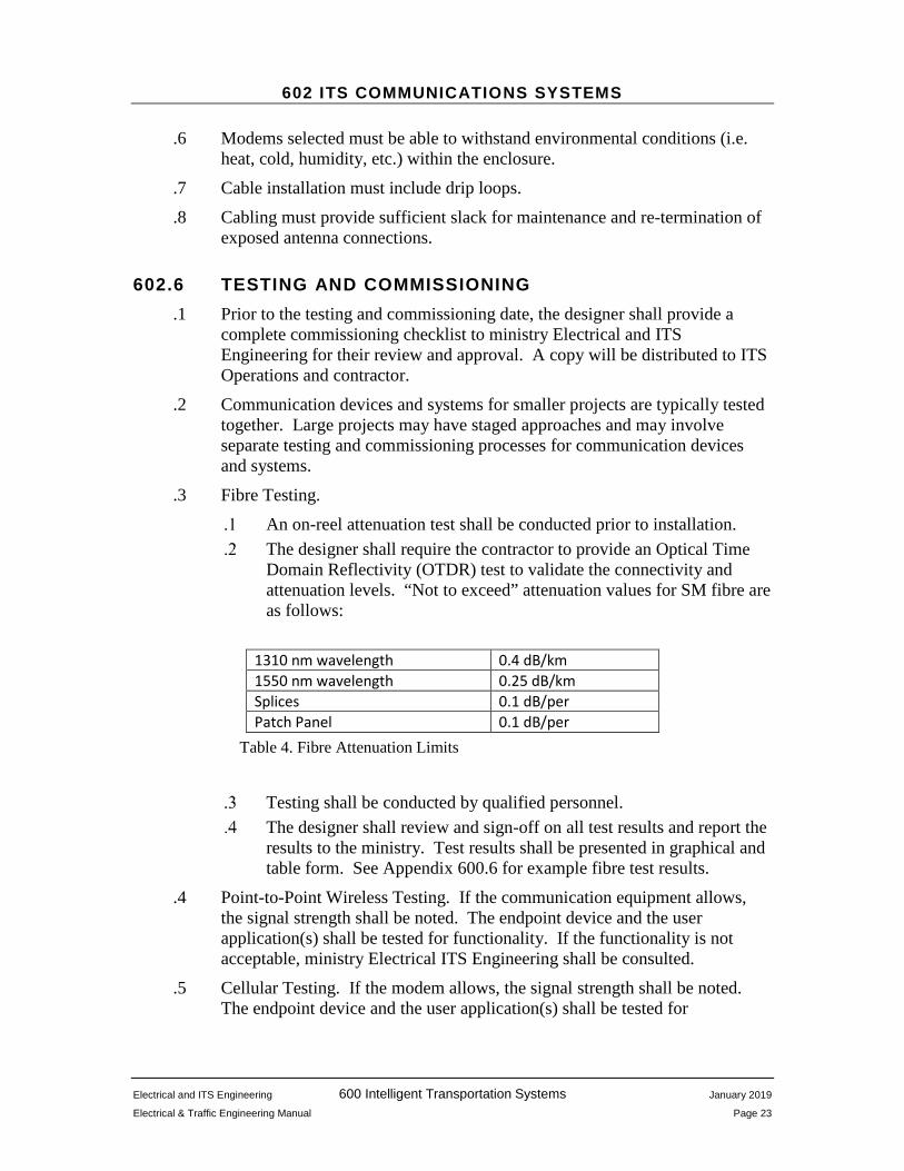
.3 Fibre Testing. An on-reel attenuation test shall be conducted prior to installation. The designer shall require the contractor to provide an Optical Time
Domain Reflectivity (OTDR) test to validate the connectivity and attenuation levels. “Not to exceed” attenuation values for SM fibre are as follows:
1310 nm wavelength 0.4 dB/km 1550 nm wavelength 0.25 dB/km Splices 0.1 dB/per Patch Panel 0.1 dB/per
Table 4. Fibre Attenuation Limits
Testing shall be conducted by qualified personnel. The designer shall review and sign-off on all test results and report the
results to the ministry. Test results shall be presented in graphical and table form. See Appendix 600.6 for example fibre test results.
.4 Point-to-Point Wireless Testing. If the communication equipment allows, the signal strength shall be noted. The endpoint device and the user application(s) shall be tested for functionality. If the functionality is not acceptable, ministry Electrical ITS Engineering shall be consulted.
.5 Cellular Testing. If the modem allows, the signal strength shall be noted. The endpoint device and the user application(s) shall be tested for

602 ITS COMMUNICATIONS SYSTEMS
Electrical and ITS Engineering 600 Intelligent Transportation Systems January 2019
Electrical & Traffic Engineering Manual Page 24
functionality. If the functionality is not acceptable, ministry Electrical and ITS Engineering shall be consulted.
.6 Dial-up Testing. The connection speed of the modem shall be noted for future reference. It is preferable that the line be checked for noise; if an unacceptable amount of noise exists, the contractor should work with the telephone utility to resolve any line issues. The endpoint device and the user application(s) shall be tested for functionality. If the functionality is not acceptable, ministry Electrical ITS Engineering shall be consulted.
.7 Satellite Testing. The modem signal strength shall be noted for future reference. The endpoint device and the user application(s) shall be tested for functionality. If the functionality is not acceptable, ministry Electrical ITS Engineering shall be consulted.
602.7 DECOMMISSIONING .1 Communication systems and/or devices may be decommissioned if one of
the following has occurred: The system and/or device are deemed obsolete, redundant, or end of
useful life; or A new communication system will replace the current system.
.2 Field devices associated with a decommissioned communication system must be transferred to the new system. Any operational interruptions must be minimized. The amount of downtime permitted is dependent on the application and should be confirmed with ministry Electrical ITS Engineering.
.3 Communication equipment (i.e. modems) removed must be returned to ITS Operations for repurposing or disposal. Data subscription services must be cancelled through IMB. Record drawings must be updated to reflect removed equipment.
.4 See Appendix 600.5 for further decommission guidance.

Electrical and ITS Engineering 600 Intelligent Transportation Systems January 2019
Electrical & Traffic Engineering Manual Page 25
603 ITS POWER
603.1 GENERAL .1 This chapter focuses on the power requirements of ITS field components.
ITS power requirements are dependent on the function of the equipment and the electrical load.
.2 Electrical installations shall meet the requirements of the latest edition of the Canadian Electrical Code (CEC), applicable Canadian Standards Association (CSA) standards, and follow ministry construction standards as detailed in the ministry Standard Specifications for Highway Construction.
603.2 POWER CONSIDERATIONS .1 Generally, the power for the system is calculated to suite the initial
requirements and then consideration is given for future expansion. .2 Utility service meters shall be installed at all new or upgraded ITS electrical
services. See 504.4.9. .3 It is recommended that ITS installations be powered by the local power
utility whenever possible. It is possible for ITS installations to be powered by alternative sources such as solar, wind, fuel cell, and internal combustion generators. Alternative power sources must be carefully evaluated to determine suitability and reliability for the application. See 603.6 for further guidance.
603.3 SERVICE .1 Electrical services shall conform to all applicable codes and standards. Refer
to 504.4 for ministry service standards.
603.4 WIRING .1 Wiring shall conform to all applicable codes and standards. Refer to 504.5
for ministry wiring standards.
603.5 BACKUP POWER .1 An Uninterruptable Power Supply (UPS) may be required to ensure
uninterrupted operation of critical equipment. .2 Regulatory ITS (see 601.4.2), such as lane control systems and VSLS, shall
have backup power that is automatically switched to in the event of a utility power failure. Backup power sources can include a separate service, generator, and/or UPS. The run time of the backup power source is based on

604 ITS SIGNS
Electrical and ITS Engineering 600 Intelligent Transportation Systems January 2019
Electrical & Traffic Engineering Manual Page 26
power outage statistics and how critical the ITS system is. The run time should provide time for maintenance staff to correct the fault of the primary power source, or allow the backup power source runtime to be extended. Regulatory systems must provide an alarm to alert maintenance staff that backup power is in use.
.3 Advisory and Informational ITS (see 601.4.3) should include a backup source of power that allows for uninterrupted operation through short outages, typically 4 to 6 hours.
DMS shall be designed to include an UPS with sufficient capacity to provide 6 to 8 hours of run time.
Cameras generally do not require a UPS.
603.6 ALTERNATIVE POWER SOURCES .1 Alternative power sources shall only be used when electrical utility power is
not available or is cost prohibitive to install. .2 For some ITS applications alternative power sources may be a viable
solution. Alternative power sources include solar, wind, fuel cell or gas/diesel generator. Engineering analysis is required to determine feasibility and practicability of alternative power sources.
.3 Regulatory ITS shall not be powered by a single alternative power source unless directed otherwise by ministry Electrical and ITS Engineering.
.4 ITS sites using alternative power should not include equipment that requires high power, such as cabinet heating.
.5 Sites where alternative power is dependent on the environment (i.e. sunlight or wind) should be analyzed by statistical data provided by weather services, such as Environmental Canada or the ministry’s Avalanche and Weather department. Site evaluations should include a study of terrain to identify any potential natural or manmade barrier that will hinder or lower a natural source of energy.
.6 Solar panels are typically mounted fixed at an angle of about 11 to 15 degrees from vertical. Tilt angles are calculated based on the location’s latitude and manufacturer’s recommendations. They may be mounted vertically in areas having a high amount of snow accumulation. Solar panels must face south to capture the maximum amount of sunlight.
.7 Wind power is an unpredictable natural resource. It is best used in combination with other methods as a supplemental source of energy. As with solar power, wind turbines must be paired up with a charge controller and storage batteries and require thorough analysis of wind patterns and speed to determine if feasible.
604 ITS SIGNS
Electrical and ITS Engineering 600 Intelligent Transportation Systems January 2019
Electrical & Traffic Engineering Manual Page 27
.8 Batteries are required to store the energy captured by photovoltaic cells or wind generation. Batteries shall be lead-acid absorbed glass mat (AGM). Design specifications must take into consideration ambient temperature, charge cycles and maintenance requirements. Batteries must be oriented vertically or horizontally as specified by the manufacturer. Regular maintenance is required to ensure capacity is within original design parameters and the integrity of the battery case has not been compromised. They should be installed in a secure cabinet.
.9 Fuel cells use electrochemical reaction of fuel oxidation to generate electricity. The type of fuel cell is typically defined by the electrolyte and fuel used. Fuels include hydrogen and hydrocarbon-based fuels (i.e. methanol, ethanol), creating by-products of water and carbon dioxide, respectively.
Fuel cells require a constant supply of fuel for operation. During the design phase it should be determined whether the location makes it practical to refuel the system.
Fuel cost and availability are also considerations. The required fuel is usually highly refined and available only through specific vendors making re-supply logistically difficult.
Fuel cells may be used as a stand-alone power source or as a supplemental power source for solar and wind powered ITS installations.
.10 Generators use an internal combustion engine to generate electrical power. Common fuels are gasoline, diesel and natural gas. Generators are used in other road construction projects and maintenance contractors are familiar with their use.
When running, generators require a constant supply of fuel. During the design phase, it should be determined whether it is practical for maintenance contractor to resupply the generator at a regular basis. Generators can also act a reliable secondary source of power for solar and wind powered ITS installations, reducing resupply work of the maintenance contractor. When generators are used as a secondary source of power, it is recommended that regular mechanical maintenance and testing be conducted as per manufacturer’s recommendations.
Generators are reliable, practical and easy to use. However, they are not sustainable as the primary source of power due to long term logistical, maintenance, and environmental cost. Careful consideration must be made if they are to be used as part of a permanent design.
The fuel capacity of the generator should be sufficient to provide logistically practical refueling intervals.

604 ITS SIGNS
Electrical and ITS Engineering 600 Intelligent Transportation Systems January 2019
Electrical & Traffic Engineering Manual Page 28
Placement of generators should avoid environmentally sensitive locations.
Careful attention must be given to fuel storage and delivery methods to reduce impact of potential fuel spills Fuel spill kits should be available on site in the event of a minor spill.
.11 ITS sites that use alternative power sources should consider additional security measures to deter and prevent damage from theft and vandalism.

604 ITS SIGNS
Electrical and ITS Engineering 600 Intelligent Transportation Systems January 2019
Electrical & Traffic Engineering Manual Page 29
604 ITS SIGNS
604.1 GENERAL .1 ITS signs make up a significant component of the ministry’s Traffic
Management and Information System. The purpose of ITS signs is to provide real-time advisory information to road users allowing motorists to react to conditions and events as they occur. Information displayed includes travel times, road open/closed status, weather conditions, and public service/safety announcements.
.2 ITS signs are comprised of two basic types: Dynamic Message Signs (DMS) and hybrid signs. DMS are text-message LED displays of various sizes and configuration and hybrid signs are a static aluminum sign augmented with a small DMS or flashing beacons.
.3 ITS signs can be controlled remotely by operators at the Regional Transportation Management Centre (RTMC), independently by an automated system, and locally (on site) by road maintenance personnel. See Chapter 607 (ATIS) for automated systems.
.4 DMS currently in use by the ministry have modular displays and use industry standard communications protocols, such as NTCIP. The discrete modules isolate failure to sections of the display and allow relatively easy field replacement of sections. The use of standard communications protocols ensures system compatibility across multiple vendors.
.5 The size of a DMS varies depending on the application. The size is expressed as the number of rows and columns of sections, or modules that make up the sign.
.6 Hybrid signs are used specific purposes, such as the Border Advanced Traveler Information System (ATIS) or Severe Weather Conditions Signs (SWCS).
.7 For ease of identification and tracking, ITS signs follow a naming convention. This convention incorporates the function as well as the location as part of the sign name. For details on sign naming see 604.4.5.
604.2 POLICY .1 The ministry policy, Guidelines for the Operation of Changeable Message
Signs (CMSs) and Portable Changeable Message Signs (PCMSs), provides guidelines for the use of CMSs and PCMSs on the British Columbia highway system. These guidelines ensure that messages displayed convey pertinent and consistent information to road users and also ensures the deployment of these devices follows established procedures. (See Technical Circular T6/16).

604 ITS SIGNS
Electrical and ITS Engineering 600 Intelligent Transportation Systems January 2019
Electrical & Traffic Engineering Manual Page 30
.2 ITS signs shall be installed in locations approved by the ministry Senior Traffic Operations Engineer.
.3 Signs shall rest in blank state or with a pre-defined message.
.4 Typically, ITS signs are controlled by the RTMC.
604.3 PLANNING .1 The location of an ITS sign must be carefully considered before it is
installed. Location selection is determined through consultation with the District and ministry Traffic Engineering. Criteria for sign location includes ensuring a sufficient sight line that allows the motorist to read and understand the sign, as well as having route options ahead so that an alternate route can be taken if required.
.2 Working in conjunction with the District and ministry Traffic Engineering site studies should be conducted to consider special applications (e.g. U-turn routes, chain-up areas, etc.), audience, traffic flow pattern, existing land use, and possible future developments.
.3 Technical considerations for sign legibility include roadway geometrics, and proximity to the well-known areas that requires regular messaging. See MUTCD (2009), Chapter 2L for additional guidance regarding legibility, visibility and design characteristics.
604.4 SIGN NAMING .1 ITS sign names shall be provided by ministry Electrical and ITS
Engineering. Sign naming will follow the convention provided below which supersedes all previous naming conventions.
.2 ITS sign names have four components that provide key information that allows users to quickly identify its function, approximate location, and direction. The format is as follows:

604 ITS SIGNS
Electrical and ITS Engineering 600 Intelligent Transportation Systems January 2019
Electrical & Traffic Engineering Manual Page 31
Function –An abbreviation describing the function of the sign or system it supports. A list of abbreviations will be kept and updated by ministry Electrical and ITS Engineering for consistency. At the time of the writing, ministry DMS are used for the following functions:
Function Abbreviation Information INFO Open/Closed OC Road Weather Information System RWIS Chain-up CHAIN Advanced Traveler Information System – (Canada/USA) Border BRDR Advanced Traveler Information System – Hwy 99/91 ATIS Advanced Traveler Information System – Lions Gate Bridge LGB Congestion Warning CONG Variable Speed Limit System VSLS Port Mann Highway 1 (Travel Time) PMH1 Parks Canada PARKS Warning Signs (Pull-outs, Icy, Slow Down, etc.) WARN
Table 5. ITS Sign Functions and Abbreviations
Locality – A 3 to 5 letter abbreviation describing the community, geographical landmark, or well-known area in proximity to the sign. A list of abbreviations will be kept and updated by ministry Electrical and ITS Engineering for consistency. XY – X refers to the highway number and Y refers to the direction of travel for which the sign is facing. If a stretch of highway uses two highway numbers, the longer highway is used. Direction of travel is based upon the overall direction of the highway, not upon the orientation of the particular segment of roadway the sign is on. Sequential Numbering – The last part of the name provides differentiation from signs that have the same three previous attributes. General rules:
• First sign in an area will be ‘1’. • The numbering increases numerically or alphabetically when signs are
added north or east of the existing sign(s). • Numbers and letters are alternated when new signs are inserted between
signs when the next sequential number or letter is not available. • ‘0’ is used for new signs south or west of sign AAAA-BBBB-XY-1. (using
the example below, INFO-HOPE-1E-0 is a new DMS south of INFO-HOPE-1E-1)

604 ITS SIGNS
Electrical and ITS Engineering 600 Intelligent Transportation Systems January 2019
Electrical & Traffic Engineering Manual Page 32
• ‘X’ will be used for new signs south or west of existing signs that does not have any letters or numbers available. Any subsequent signs added to south or west of this sign will be have another ‘X’ added to its name. (i.e INFO-HOPE-1E-0AX is a new DMS inserted between DMS INFO-HOPE-1E-0A and INFO-HOPE-1E-0).
Note: When appropriate, it is recommended to select another geographical location rather than using ‘X’. ITS Engineering will provide direction and guidance.
In the example below, new signs are sequentially added to the original three signs (i.e. INFO-HOPE-1E-1, -2, -3).
New Signs Applicable Rule
1 INFO-HOPE-1E-1A Numbers and letters alternate 2 INFO-HOPE-1E-1B Sequential Numbering 3 INFO-HOPE-1E-1A1 Numbers and letters alternate 4 INFO-HOPE-1E-0 0 (zero) is used new signs south or west of first sign 5 INFO-HOPE-1E-0A Numbers and letters alternate 6 INFO-HOPE-1E-0AX X inserted when there is no alternating character 7 INFO-HOPE-1E-0AXX X inserted when there is no alternating character
Table 6. DMS and Warning Sign Naming Example
Figure 3. ITS Sign Naming Example

604 ITS SIGNS
Electrical and ITS Engineering 600 Intelligent Transportation Systems January 2019
Electrical & Traffic Engineering Manual Page 33
604.5 DMS DESIGN .1 DMSs shall be designed to meet the requirements of NEMA TS-4 Hardware
Requirements for Dynamic Message Signs (DMS) with NTCIP 1203 (v03). .2 Large DMSs shall be installed on cantilever or sign bridge structures
designed and fabricated in accordance with ministry Electrical and Signing Material Standards Section 306 Cantilever and Sign Bridge Structures. The sign structure supplier shall also provide the hardware required to attach the sign to the structure. Sign bridge and cantilever structures will require engineered concrete bases. A catwalk to service the sign face is not normally required.
.3 The ministry standard for a full-sized DMS is a 2-line, 20 column line-matrix made up of high-density LED modules. These signs can display complete alphanumeric messages.
.4 Small DMSs have a lesser number of rows and/or columns. Warning signs have limited display space and may be a hybrid type (see 604.1). Small DMS are installed on ministry standard structures.
.5 DMSs must be approved for use by Electrical and ITS Engineering and shall be listed on the ministry Recognized Products List (RPL).
.6 A DMS or warning sign requires a control cabinet and an electrical service panel with a utility power meter.
The control cabinet may be mounted on the same pole as the electrical service, or on the pole used for the sign. If a larger cabinet is required a ministry approved ITS cabinet shall be used. If more than two cabinets are required to be mounted on the pole, consult with Electrical and ITS Engineering.
The service panel and meter shall be designed as described in Section 504.4 of this manual.
Electrical service panel and utility power meter shall be installed as specified in the ministry Standard Specifications for Highway Construction SP635-2.4.1 to SP635-2.4.20.
A full sized 2 X 20 DMS shall have a 30A or 100A metered service depending upon power requirements. The service equipment and sign controls may also be mounted in a ministry approved electrical kiosk. See Chapter 603 for power and UPS guidance.
.7 Design considerations include maintenance, ease of access, communications, power quality and reliability, clear-zone and all ministry specifications for roadside construction.
.8 Often, a new sign can be installed on an existing structure. In such cases, the structure must be evaluated by ministry structural engineering ¬¬¬-personnel to ensure it is meets current specifications.

604 ITS SIGNS
Electrical and ITS Engineering 600 Intelligent Transportation Systems January 2019
Electrical & Traffic Engineering Manual Page 34
604.6 INSTALLATION .1 The installation shall be undertaken by a qualified electrical contractor and
follow all applicable codes and standards. .2 Prior to installation the operation of the sign shall be confirmed by the
supplier or designate at their place of business. All aspects of the sign and supporting systems should function as specified below under Testing and Commissioning. The modem that is to be used in the actual operation of the sign (cellular, PSTN or satellite) must be included as part of the testing to confirm device and network settings are correct. Communication testing may be exempt if the communication is by fibre in which case testing can take place in the field.
604.7 TESTING AND COMMISSIONING .1 Prior to the testing and commissioning date, the contractor shall provide a
complete commissioning checklist to the Project Supervisor who shall forward it to the Designer for review and acceptance.
.2 On-site commissioning shall be done by the contractor and, where applicable, the Designer. Commissioning shall include the following, but not be limited to:
Communication Integration into ATMS, including network settings Display modules (test message from ATMS) Confirm display of specified font sizes Photocell response to bright and dark conditions Communication and power failure modes UPS operation Local operation Error reporting Cabinet environmental control systems
.3 Once the ITS sign is commissioned and integrated into the ATMS, it shall remain blank. ministry ITS Operations will notify the RTMC that it is ready for use.
.4 The contractor shall provide a mark-up for record drawing purposes.
604.8 DECOMMISSIONING .1 ITS signs may be decommissioned if the sign is deemed obsolete or
redundant.
604 ITS SIGNS
Electrical and ITS Engineering 600 Intelligent Transportation Systems January 2019
Electrical & Traffic Engineering Manual Page 35
.2 ITS Operations shall remove the sign from the ATMS and other associated systems.
.3 DriveBC will be notified that the sign is removed from service.
.4 signs and ancillary equipment shall be removed from the site. Communication equipment (i.e. modems) removed must be returned to ministry ITS Operations for repurposing or disposal.
.5 Record drawings must be updated to reflect removed equipment.
.6 The sign structure may be re-used, if not it should be removed.
.7 See Appendix 600.5 for further decommission guidance.

Electrical and ITS Engineering 600 Intelligent Transportation Systems January 2019
Electrical & Traffic Engineering Manual Page 36
605 CAMERAS
605.1 GENERAL .1 Video cameras make up a significant component of the ministry’s Traffic
Management Information System. They are used by the ministry to provide traffic and weather conditions to the public and also to support ministry operations and construction projects.
.2 This chapter describes background, policy, site selection, design, installation, commissioning, testing, handover, maintenance and decommissioning of cameras and camera systems.
605.2 BACKGROUND .1 Cameras were initially used by the ministry for internal ministry operations
such as reversible lane control systems, swing bridges, and monitoring of tunnels.
.2 Camera use was expanded to include roadside cameras to provide the public a means to view remote road, weather, and traffic conditions. Over time, the applications for cameras has expanded to include construction site monitoring, traffic management (operations), and wildlife detection.
.3 The increase in use of cameras has been due to public demand, improved communications technologies, and decreased operational costs. The near real-time situational awareness provided by images is beneficial to both the public and ministry operations. The public benefits from road, traffic, and weather information that provide guidance for travel planning and ministry operations and construction projects benefit from remote monitoring
.4 Ministry cameras are used for: Road and weather conditions; Traffic conditions; Reversible lane control systems; Traffic management; Construction projects; Special events; Security; DMS message verification; Assisting emergency responders; Wildlife Detection Systems;

606 SENSORS
Electrical and ITS Engineering 600 Intelligent Transportation Systems January 2019
Electrical & Traffic Engineering Manual Page 37
.5 The preferred camera type is Pan-Tilt-Zoom (PTZ) with the following functionalities: remote control optical zoom (minimum 10X), 360 degree panning, and 180 degree tilt. In locations where power and communications bandwidth is limited PTZ cameras may not respond adequately and stationary cameras may be used. Examples of this are remote locations where there is no roadway lighting and an infra-red illuminator is required to illuminate the field of view for night images.
.6 The ministry uses digital cameras with TCP/IP networking. Analog cameras are still in operation where it is cost-prohibitive to replace them. These cameras require a separate analog-to-digital conversion device and network interface to format and transmit the image over the TCP/IP network.
.7 An important component of the camera system is the enclosure. The enclosure provides a weatherproof housing for the camera, and may include the modem, environmental controls, and power supply. Enclosures types vary to suit the application (i.e. pan-tilt-zoom, stationary, and should have a minimum Ingress Protection rating of IP66. See the ministry Recognized Products List for approved enclosures.
605.3 POLICY .1 Camera locations are derived through consultation with the Regions,
Districts and Camera Program Manager based upon the criteria described below.
.2 Cameras are generally strategically placed to provide traffic, weather, and road conditions as well as monitor the status of known congestion points such as border crossings or inland ferry queues. Generally, in urban areas cameras are prioritized for traffic monitoring and in rural areas cameras are placed at locations subject to inclement weather.
.3 Cameras are subject to privacy and security policies. See Chapter 610.
.4 Cameras are often installed to monitor the status of major construction projects and may provide images to ministry personnel and/or the public. Construction cameras are often left in place and made public once the project is complete.
605.4 SITE SELECTION .1 Selecting a location for a camera requires consideration of many criteria,
including: local preferences, camera function, availability of communications, power, and lighting, proximity to other cameras, and roadway construction policies.
.2 Before beginning a design, the exact location of the camera must be established. The steps are as follows:

606 SENSORS
Electrical and ITS Engineering 600 Intelligent Transportation Systems January 2019
Electrical & Traffic Engineering Manual Page 38
Consultation with the Region, District and Camera Program Manager to agree upon a general area.
Identify potential locations within the general area. Evaluate each location, considering:
.1 Camera field of view: sun washout, obstructions, view of road, privacy, commercial entities.
.2 The function of the camera is best served: weather, road conditions, traffic, security, construction view.
.3 Communications: availability of ministry fibre optic network, cellular service and strength and quality of cellular signal,
.4 Power: availability of utility power, sun exposure if solar.
.5 Lighting: existing roadway lighting, if an additional luminaire is required, infrared illuminator required if no roadway lighting.
.6 Proximity to known landmarks: cross road, rest area, brake check, geographical.
.7 Availability of infrastructure: existing poles, lighting, electrical service, conduit.
Maintenance: room for service vehicles, including bucket trucks; consider winter road conditions with snow build-up. .1 Compliance with roadside construction standards: clearances
from overhead utility lines, underground checks, clear zones. .2 Installation cost;
See Appendix 600.1 for a complete camera warrant check list.
605.5 DESIGN .1 The first step is to contact the Camera Program Manager. The Camera
Program Manager will ensure that all policies and procedures related to the installation of a new camera are followed. These include ensuring:
.2 Engineering drawings are created or updated;
.3 Security procedures are followed;
.4 Approved equipment is used;
.5 Information is added to the camera program database;
.6 Privacy Impact Assessment (PIA) is completed.
.7 IMB is informed and provided with networking security information.
.8 Camera site design should consider the following:
.9 Field of View: The camera view should be free of obstruction from structures, power/telephone lines, vegetation etc. and offer a clear view of as

606 SENSORS
Electrical and ITS Engineering 600 Intelligent Transportation Systems January 2019
Electrical & Traffic Engineering Manual Page 39
much roadway as possible and include special infrastructure such as break checks, rest areas, or chain up areas if applicable. The field of view should not include private residence or commercial entities.
.10 Lighting: The viewing area should take advantage of existing roadway lighting for night images. A new luminaire can be installed, but should located where a motorist would normally expect it, such as at a cross road or pull out. If this is not possible, an infra-red illuminator may be used. If an infra-red illuminator is used with a pan-tilt-zoom camera, the infra-red illuminator must move with the camera to illuminate all fields of view. It may be more cost-effective to use a stationary camera with a stationary infra-red illuminator.
.11 Ambient Light: To ensure consistent ambient light, it is preferable to face the camera north. Where this is not possible the camera should be oriented in the direction that has the most elevated horizon (such as distant mountain(s) or trees) to reduce morning/evening solar wash out.
.12 Mounting Structure: Typically cameras are mounted on ministry standard poles; the shaft height for these poles varies from 6.5 to 11.0 meters. Cameras should be mounted at the highest point possible between 8.0 – 11.0 meters. Heights greater than 11.0 meters can make maintenance awkward and do not offer significant advantage. Cameras shall not be mounted on bridge structures without consultation with ministry Bridge & Structural Engineering. Vibration and difficulty of access for maintenance personnel should be taken into consideration when mounting cameras on bridge structures. With PTZ cameras, the mounting hardware and structure should not interfere with the desired field of view.
.13 Road wash: It may be preferable to orient the camera in the same direction as traffic at the 8.0m mark or higher in areas where road wash is significant.
.14 Maintenance: The camera should be located to facilitate access by maintenance personnel taking into consideration potential snow build-up during winter months.
.15 Power Cabling: Generally, it is preferable to keep cable runs from the electrical service as short as possible. Selection of a one lighting pole from a group of poles should take into consideration the available roadway lighting and distance from the electrical service. The camera should be installed on the same pole as the electrical service-panel if all other aspects of the installation can be satisfied.
.16 DMS Verification: If a camera is located in proximity to a DMS, the camera can be used to confirm operation of the sign.
.17 Construction Standards: If new structures are installed the installation must follow all ministry guidelines regarding clear zones and breakaway devices and adhere to construction standards as defined in the appropriate sections of

606 SENSORS
Electrical and ITS Engineering 600 Intelligent Transportation Systems January 2019
Electrical & Traffic Engineering Manual Page 40
this manual and the ministry Standard Specifications for Highway Construction.
605.6 INSTALLATION .1 Prior to onsite installation, power, communication, and camera configuration
shall be tested at the contractor’s place of business with coordination from ITS Operations. The operational modem (cellular, PSTN or satellite) must be used as part of the pre-installation testing – this is to confirm that the device and network settings are correct prior to onsite installation.
.2 ITS Operations shall confirm with the installer on site regarding sight lines, PTZ tours, programs/scripts and communication strength.
605.7 TESTING AND COMMISSIONING .1 Testing and commissioning will vary based upon the degree of complexity of
the camera system. Standard installations where the camera, cellular modem, and supporting equipment are contained in an enclosure will require simple operational testing to ensure the camera and communication equipment function as designed. More complex installations will require confirmation of battery voltages, solar charge controller operation, satellite parameters and signal strength, infra-red illuminator operation, and operation of remote devices, if so equipped. A commissioning checklist shall be provided to the contractor by the Camera Program Manager; this will be completed by the contractor under the guidance of ITS Operations and the Camera Program Manager. Once complete, the Camera Program Manager will distribute to ministry Electrical and ITS Engineering for review and acceptance. Once accepted, a copy will be distributed the ministry Electrical Maintenance Contractor.
.2 Onsite testing and commissioning shall be carried out by the contractor under the guidance of ministry ITS Operations. Testing shall include:
Communications signal strength and quality; Integration into other systems, if required; Low light camera performance; Infra-red illuminator operation and performance, if applicable; Camera aiming or pan-tilt-zoom positions, as applicable; Uploading to correct server at correct interval;
.3 Once complete the contractor shall provide a mark-up drawing showing any changes to the design and/or existing infrastructure.
606 SENSORS
Electrical and ITS Engineering 600 Intelligent Transportation Systems January 2019
Electrical & Traffic Engineering Manual Page 41
605.8 ACCEPTANCE .1 Once accepted by ministry ITS Operations notification shall be sent to the
ministry Camera Program Manager who will inform Electrical and ITS Engineering, the District, and the RTMC.
605.9 MAINTENANCE .1 Preventative and corrective maintenance is normally performed by ministry
Electrical Maintenance Contractor. Preventative and corrective maintenance is detailed in the applicable Electrical Maintenance Agreement for the service area. This agreement stipulates limits to corrective maintenance and multiple call outs may result in additional charges to the ministry.
.2 Upon completion of the installation, the designer shall provide ministry Electrical and ITS Engineering and the Camera Program Manager with a copy of the operations and maintenance information along with any unique preventative maintenance requirements, such as annual satellite signal strength testing or battery load testing. Non-standard maintenance requirements will be added to the Local Area Maintenance Specifications.
.3 Ministry ITS Operations is the initial point-of-contact for day to day technical support; all camera related communications should include the ministry Camera Program Manager.
605.10 DECOMMISSIONING .1 See Chapter 610 - Privacy and Security for appropriate standards for
cameras. .2 See Appendix 600.5 for general decommissioning process.
Electrical and ITS Engineering 600 Intelligent Transportation Systems January 2019
Electrical & Traffic Engineering Manual Page 42
606 SENSORS
606.1 GENERAL .1 Sensors provide information from the field that is used by operational control
systems to make decisions and take appropriate action. Accurate and reliable sensors are essential for effective ITS operations. The ministry employs a variety of sensors based upon the requirements of the system.
.2 This section covers various sensor technologies used by the ministry and their typical applications.
606.2 BACKGROUND .1 The ministry uses many types of sensors for ITS purposes. The most
common sensor is the inductive loop used in traffic controllers for vehicle detection. Other sensors include radar, temperature, precipitation, and optical all of which are used for various applications such as detect vehicle travel speeds, volume, occupancy, vehicle classifications, wildlife detection, weather, and road surface conditions. The increased level of accuracy and versatility has allowed for more sophisticated ITS systems such as the Variable Speed Limit System (VSLS) and Wildlife Detection System (WDS).
606.3 INDUCTIVE DETECTOR LOOP .1 This section focuses on the inductor detector loop for ITS purposes only. .2 Inductive loops are simply cables buried in the pavement. The cable is run
from the roadside out to a circular or rectangular detection area where it is ‘looped’ around several times, then run back to the roadside. A detector card feeds a signal into the loop that resonates at a particular frequency, typically in the kilohertz range.
.3 When a large mass of metal (a vehicle) passes in proximity to the detection area, the inductance effectively changes, which in turn alters resonant frequency signifying the presence of a vehicle. Detectors typically have different frequency and sensitivity settings to reduce crosstalk between loops and for tuning, respectively. See 406.6.11 for traffic control cabinet applications for intersection. See ministry Traffic Controller Assembly Section 600 for detailed technology background.
.4 Inductive loops can be installed two ways: cut into the road after pavement is down, or pre-formed and installed before the final lift of pavement is down. Loops that are cut into the pavement will typically need to be replaced at some point. Preformed loops installed before the final lift of pavement have a

606 SENSORS
Electrical and ITS Engineering 600 Intelligent Transportation Systems January 2019
Electrical & Traffic Engineering Manual Page 43
much longer service life. Installation may be difficult in colder regions and cannot be completed in rainy conditions. Pre-formed loops, even if installed prior to road paving, will require cutting into the pavement for future modifications.
.5 Loops are normally installed in groups of 2 or more as a single loop is generally not sufficient for data input. Multiple loops strategically positioned in a lane can provide approximate speed, volume, occupancy, queue length and approximate vehicle classification. Detector loops are applied to ITS projects such as Advanced Traveler Information Systems (ATIS) for queue wait time, active bus lane warning signs, and count stations.
.6 Specialized loops can also be used for other applications such as warning sign activation and cyclist detection. Detection of some bicycles may not be reliable due to low metallic content (i.e. carbon fibre).
606.4 RADAR DETECTION .1 Radar sensors use high-frequency electromagnetic waves to determine the
size, distance, direction, and velocity of moving objects. A roadway radar unit uses a low power transmitter to send electromagnetic pulses which are reflected from objects back to the source. The changes in the reflected electromagnetic waves are captured by the radar receiver and processed to determine the object size, distance, direction and velocity.
.2 Depending on the radar sensor’s capability, a single detector can be mounted on a pole and be orientated to cover multiple lanes, including vehicles traveling in different directions.
.3 Because of their small size and low weight radar sensors can be mounted on most infrastructure. They typically require no underground work, making them suitable for applications where it is impractical or too expensive to install inductive loops. They must be configured and positioned to cover the target detection zones and should be periodically examined to ensure they are functioning as intended.
.4 A series of radar detectors along a highway corridor can provide travel time, incident detection, vehicle classification, and volume information. A higher concentration of radar detection increases the resolution for travel time and queue lengths. In addition, a high concentration of radar detectors provides some redundancy when data is unavailable due to technical issues.
.5 Some radar detectors can detect cyclists and pedestrians and may be deployed in cyclist and pedestrian crossing warning systems.

606 SENSORS
Electrical and ITS Engineering 600 Intelligent Transportation Systems January 2019
Electrical & Traffic Engineering Manual Page 44
606.5 VIDEO DETECTION .1 Digitized video and image processing may be used for vehicle detection and
classification. This technology continues to evolve and some systems are capable of counting, speed, and detection of cyclists and pedestrians.
.2 In simple terms video detection is based on capturing sequential frames and determining if the changes between frames are caused by vehicles, cyclists or pedestrians. It should be noted that changes to images can be caused by other factors such as changing weather, large shadows, or wildlife and these systems can be challenged when attempting to distinguish between video that is relevant and video that is not. Also, low visibility conditions such as fog, may affect functionality. When selecting a video detection sensor, it is important to consider the conditions it will be subject to as well as the environmental conditions to ensure reliable detection.
.3 Video detectors consist of a camera and video processing unit. The video processing unit can be integrated into the camera or separate hardware located in the cabinet.
.4 In most systems, detection zones must be configured by the user. It is possible for video detection software to “learn” how an intersection or roadway works and setup detection zones automatically. Detection zones should be confirmed by Traffic Engineering prior to operation.
.5 Thermal imaging cameras may be used for special applications such as wildlife detection.
.6 The video used for detection can be used for other purposes such as traffic monitoring for public use or ministry operations.
606.6 PROBE BASED SAMPLING .1 Cellular phones, automobiles and other mobile devices now commonly have
Bluetooth and Wi-Fi capabilities. By sampling and matching the Media Access Control (MAC) addresses of the device at two points of known distance and measuring the time of travel between these two points, the travel speed can be calculated. Depending on the vendor these devices may include other capabilities such as error filtering and statistical analysis.
.2 Bluetooth and Wi-Fi sensors must have at least two nodes separated by a distance to estimate speed and travel time. The MAC addresses collected at each node is transmitted to a centralized server where it is processed to determine the approximate traffic speed. Sensors and systems should include an anonymized MAC address feature to ensure that privacy concerns are met. IMB shall be consulted for Privacy Impact Assessment (PIA) concerns. Refer to Chapter 610 Privacy and Security for guidance.

606 SENSORS
Electrical and ITS Engineering 600 Intelligent Transportation Systems January 2019
Electrical & Traffic Engineering Manual Page 45
.3 The location of sensors should be considered carefully to include travel corridors that have a regular volume to ensure that there is sufficient sample size for an accurate calculation. Sensors should be placed between two points that have few roadway exits to ensure vehicles are moving through two consecutive points. Higher match-counts increase accuracy of the data. Some systems will not produce a valid travel time if the processing algorithm determines that the sample size is insufficient. Traffic Engineering should be consulted for sensor placement to ensure sampling is achieved at strategic locations.
.4 Bluetooth and Wi-Fi detection sensors typically require an external processing service to provide the analysis. Device administration may be required be to done on an external web portal. When selecting Bluetooth and Wi-Fi detection devices and systems, data processing services that must be acquired outside ministry resources must be further considered; IMB shall be consulted prior to system and/or service acquisition. Refer to Chapter 610 Privacy and Security for guidance.
.5 The data from Bluetooth and Wi-Fi detection sensor systems can be used for Traffic Engineering statistical studies, operational awareness for real-time traffic management (i.e. RTMC), and populating DMSs with live travel times (i.e. ATIS).
606.7 ENVIRONMENTAL SENSORS .1 Environmental sensors are used on roadways to provide real-time road and
weather conditions. The data collected from these sensors and systems is used together with traffic data to provide comprehensive monitoring of roadway conditions. For example, Variable Speed Limit Systems use road conditions and traffic data to recommend safe traveling speeds.
606.7.2 Weather Sensors .1 Weather conditions have a direct impact on driver behavior and driving
conditions. Weather data can be used to better manage transportation routes that suffer from inclement weather.
.2 Weather sensors can detect precipitation, fog, wind speed, temperature, and more. Depending on the vendor and model, sensors can use a variety of technologies and methodologies to collect this data, including spectroscopic analysis, and physical probes (e.g. thermometer, anemometer, etc.).
.3 Sensors should not be influenced by natural or man-made objects such as vegetation or proximity to heat generating equipment such as transformers, luminaires, etc. ministry Avalanche and Weather technicians should be consulted for weather sensor placement.
606 SENSORS
Electrical and ITS Engineering 600 Intelligent Transportation Systems January 2019
Electrical & Traffic Engineering Manual Page 46
606.7.3 Road Surface .1 Road surface sensors detect how environmental conditions affect the road by
indicating if the road is bare, wet, icy, slushy or slippery. Sensors can be in the form of a probe or non-intrusive (i.e. spectroscopic).
606.7.4 Ambient Light .1 Ambient light sensors can provide another subset of data for ITS algorithms.
Ambient light sensors should be normally faced north and be situated away from artificial light sources, such as roadway lighting, vehicle headlights, electronic signage, etc. Mounting the sensor high can avoid the effects of unwanted light sources.
.2 Photoelectric cells (PEC) are used to control roadway lighting, switching luminaire circuits on and off based upon ambient light levels. Light sensors can provide several outputs such as DC signal or binary output to indicate the light level.
606.8 DESIGN .1 Sensors must be industrial grade for operations in the field and must have
CSA or equivalent certification. Any equipment or protective enclosures that reside outside of a cabinet must have an appropriate Ingress Protection (IP) or National Electrical Manufacturers Association (NEMA) rating for outdoor use.
.2 When sensors and associated systems are used in a networked environment they must meet IM/IT requirements from IMB with regards to data structure, networking and cybersecurity best practices and policies. Refer to Chapter 610 Privacy and Security for guidance.
.3 Sensors may require a control cabinet and a metered electrical service. Where practical, sensors should be powered from existing services. Protection such as fuses, surge protectors and/or lightning arrestors shall be included when required by the design or recommended by the sensor manufacturer. See Chapter 603 ITS Power for additional guidance.
.4 Sensor ancillary equipment should be housed in a ministry approved cabinet.
.5 The mounting of sensors shall follow the procedures specified by the manufacturer. Consideration should be given to vibration, water ingress, vehicle road-wash, maintenance, damage by vehicles, vandalism, and any other effects particular to the surrounding area.

606 SENSORS
Electrical and ITS Engineering 600 Intelligent Transportation Systems January 2019
Electrical & Traffic Engineering Manual Page 47
606.9 INSTALLATION .1 The installation shall be undertaken by a qualified electrical contractor. The
designer shall define contractor qualifications and experience, if required. For trial and evaluation of new sensors, it may be advantageous to invite a manufacturer representative to provide training and demonstrate correct installation procedures.
.2 Prior to installation in the field, the sensor, communications equipment, and any other components shall be tested at the contractor’s place of business or at a location agreed upon with ministry ITS Operations. The operational modem (cellular, PSTN or satellite) must be used in the testing to confirm that the device and network settings are functioning correctly.
.3 Calibration, if applicable, shall be done as per manufacturer’s instructions.
606.10 TESTING AND COMMISSIONING .1 Prior to the testing and commissioning date, the designer shall provide a
complete commissioning checklist to Electrical and ITS Engineering for their review and approval. A copy will be distributed to ministry ITS Operations and contractor.
.2 A period of time may be required to validate and confirm the accuracy of the sensor(s). Electrical and ITS Engineering will provide testing criteria and parameters.
606.11 DECOMMISSIONING .1 Sensors may be decommissioned if one of the following has occurred:
The system is deemed obsolete or redundant; or A new system will replace the existing system.
.2 Systems associated with decommissioned sensors must be removed to avoid errors.
.3 Sensors and its ancillary equipment shall be removed from the site. Communication equipment (i.e. modems) removed must be returned to ministry ITS Operations for repurposing or disposal.
.4 Record drawings must be updated to reflect removed equipment
.5 See Appendix 600.5 for general decommissioning process.
Electrical and ITS Engineering 600 Intelligent Transportation Systems January 2019
Electrical & Traffic Engineering Manual Page 48
607 ADVANCED TRAVELLER INFORMATION SYSTEMS
607.1 GENERAL .1 This chapter provides general guidance regarding policy, planning, design,
installation, testing, commissioning, maintenance, and decommissioning of Advance Traveler Information Systems (ATIS).
607.2 BACKGROUND .1 ATIS is a system designed to advise motorists of potential delays or
estimated travel times at key areas such as congested urban highways, border crossings, tunnels and bridges.
.2 Generally, ATIS includes vehicle detector sensors placed at strategic locations to detect volume, queues, congestion, or incidents. For example, data is used by software algorithms to determine messages displayed on strategically located DMS’s advising motorists of alternate routes in real time. The information can also be shared through DriveBC and other subscription services.
.3 Data collection and processing methods may vary between different systems.
607.3 POLICY .1 ATIS are typically used to provide travel-time for routes that are normally
congested but are served by several roadways. Traffic Engineering shall be consulted for further understanding of the road networks and travel patterns prior to design.
.2 ATIS are advisory systems that provide estimates. Information provided by ATIS is only guidance to the public. There may be a margin of error dependent on sensor accuracy, algorithm used, sample size, sampling method, and time of day.
.3 Any possible data collected through ATIS that may impact privacy should be referred to Director, Security and Privacy, IMB. See Chapter 610, Privacy and Security.
607.4 PLANNING .1 A preliminary study and conceptual design shall be completed to understand
the requirements, system options, and cost.
608 REVERSIBLE LANE CONTROL SYSTEMS
Electrical and ITS Engineering 600 Intelligent Transportation Systems January 2019
Electrical & Traffic Engineering Manual Page 49
.2 Traffic Engineering shall provide input to DMS and sensor locations to ensure that the correct data is collected and information is displayed at strategic locations that allows the motorist to choose an alternate route.
.3 Electrical and ITS Engineering shall provide input to the feasibility of DMS and sensor locations based on the availability of power and communication infrastructure.
.4 IMB shall be consulted for any network, privacy, security and software requirements.
.5 RTMC shall have read and write control of any DMS associated with any ATIS in the event of emergency message (e.g. Amber Alert) and incident management.
607.5 DESIGN .1 All ATIS system information must be detailed on ministry electrical
drawings and submitted to the ministry Electrical and ITS Engineering for acceptance. The designer shall define all installation details, specifications and information required for a contractor to supply and install the equipment. Electrical and ITS Engineering may request additional deliverables from designer. See Appendix 600.7 for ITS project checklist guidance.
.2 See Chapter 602 for communication design guidance.
.3 See Chapter 603 for power design guidance.
.4 See Chapter 604 for DMS design guidance.
.5 See Chapter 606 for sensor design guidance.
.6 The system shall be designed for reliability, durability, and ease of maintenance.
607.6 INSTALLATION .1 The installation shall be performed by a qualified contractor as part of the
construction contract. The designer shall define contractor qualifications and experience, if required.
.2 ATIS are made up of different sub-components (DMS, sensors, processing unit, etc.). Prior to field installation, each sub-component of the system shall be tested individually.
607.7 TESTING, CALIBRATION AND COMMISSIONING .1 Testing of the ATIS shall be done by designer and/or system integrator.
Testing plans shall be reviewed and approved by ITS Engineering.

608 REVERSIBLE LANE CONTROL SYSTEMS
Electrical and ITS Engineering 600 Intelligent Transportation Systems January 2019
Electrical & Traffic Engineering Manual Page 50
Completed test results shall become part of the project documentation delivered to the ministry.
.2 ATIS deployment may require a longer testing period to determine if it is accurate and effective. Field tests should be conducted to determine system accuracy. Designers should be prepared to reevaluate and adjust travel-time algorithms after the initial commissioning process.
607.8 MAINTENANCE .1 Maintenance shall be undertaken by ministry Electrical Maintenance
Contractor. A Local Area Specification (LAS) shall be produced as part of the project documentation. See Appendix 600.3 for LAS example.
.2 Recalibration of the system may be required periodically. Designers shall provide a recalibration schedule for all sensors used. Normally, calibration of the overall system should be conducted annually.
.3 Upon completion of the installation the designer shall provide ministry ITS Engineering and ITS Operations with manuals and preventative maintenance checklists. See Chapter 609 for maintenance guidance.
607.9 DECOMMISSIONING .1 ATIS may be decommissioned when there is no longer a requirement for its
respective travel/delay time information, or if the road network has changed. Traffic Engineering will provide guidance on whether a system is still required for the road network.
.2 After the decommissioning process, ATIS sub-components may be used for other systems.
.3 See Appendix 600.5 for the general ITS device decommissioning process for ATIS sub-components.

Electrical and ITS Engineering 600 Intelligent Transportation Systems January 2019
Electrical & Traffic Engineering Manual Page 51
608 REVERSIBLE LANE CONTROL SYSTEMS
608.1 GENERAL .1 Reversible Lane Control Systems (RLCS) or counterflow systems reduce
traffic congestion during morning and afternoon peak periods. During this time, an extra lane is created for traffic in the peak direction by reversing the flow of traffic in one of the lanes in the off-peak direction. The reversed lane is known as the counterflow lane because it carries traffic in the opposite direction.
.2 This section is a high-level overview of RLCS which shall include policy, planning, design, documentation, installation, commissioning, testing and maintenance, and decommissioning.
.3 Refer to Chapter 409, for further information regarding lane use traffic control signals.
608.2 BACKGROUND .1 A reversible lane (counterflow lane) is a lane in which traffic may travel in
either direction to improve traffic flow during rush hours. .2 Traffic control devices may include signals, signs, pavement markings, gates,
and delineation. .3 Reversible lanes are found at tunnels and bridges, where adding additional
lanes to existing infrastructure to handle increased rush hour traffic is often cost prohibitive or impractical.
.4 Reversible lanes are an effective means of increasing roadway capacity as they take advantage of the unused capacity of the minor flow direction to increase capacity in the major flow direction.
608.3 PLANNING AND DESIGN .1 The information below is a general and high-level overview. Control details
and equipment are not discussed as these are specific to each design. .2 The Transportation Association of Canada (TAC) Guidelines for the
Planning, Design, Operation and Evaluation of Reversible Lane Systems shall be followed.
.3 RLCS uses multiple lane-use traffic signals that span the length of the roadway (i.e. tunnel or bridge). Each instance of the lane-use traffic signal shall have a localized Conflict Monitoring Unit or Malfunction Monitoring Unit (CMU or MMU) (similar to signalized intersections) to ensure that signal heads do not display conflicting states.

608 REVERSIBLE LANE CONTROL SYSTEMS
Electrical and ITS Engineering 600 Intelligent Transportation Systems January 2019
Electrical & Traffic Engineering Manual Page 52
.4 The lane-use traffic signals shall be changed in phases similar to three-colour operations, to allow a gradual transition for drivers. The timing and phases shall be determined by Traffic Engineering.
.5 Contrary to the TAC guidelines referenced above, at least two lane-use traffic signal heads shall be visible to the driver at any one time.
.6 To ensure the operator can visually confirm reversible lanes are clear of vehicles before transitions are initiated, a closed circuit video system shall be included in the design. Lighting shall be provided to permit operation of the video system during night.
.7 Controllable gates must be installed at key points to prevent drivers from entering reversed or closed lanes.
.8 The design shall include control unit redundancy that includes automated switch over to a secondary master control unit in the event of a primary master control unit failure. The master control unit software shall also be installed on a backup server.
.9 Uninterruptible Power Supplies (UPS) shall be of sufficient capacity to ensure system operation through transition to secondary power and shall include a generator with automated switching. If practical, power should be supplied from two separate power grids. Alarms shall be actuated when there is a loss in primary power.
.10 Communication between all lane traffic control signals and the master control unit must be designed to include redundant communication paths and must be dedicated to sole use of signal control.
.11 All system alarms, events, changes, status, and transitions must be time-date stamped and recorded for legal purposes.
.12 Diagnostics and fault management should be considered in the design. As the lane control systems are operator controlled and monitored, alarms should be enabled at the operator’s work station.
608.4 DOCUMENTATION .1 As RLCS are all different in design and operations, it is expected that the
designer shall provide comprehensive operation, incident management, and maintenance manuals. The designer shall provide detailed training sessions and packages for engineering and maintenance contractors.
.2 See Appendix 600.7 for general ITS project checklist guidance.
608.5 TESTING AND COMMISSIONING .1 Prior to the testing and commissioning date, the designer shall provide a
complete commissioning checklist to Electrical and ITS Engineering for their

608 REVERSIBLE LANE CONTROL SYSTEMS
Electrical and ITS Engineering 600 Intelligent Transportation Systems January 2019
Electrical & Traffic Engineering Manual Page 53
review and acceptance. A copy will be distributed to ITS Operations and maintenance contractor.
.2 System testing will be completed off-site before installation. Once installed, field testing shall be scheduled to minimize traffic disruption and may be required to be done at night. District Operations and Traffic Engineering shall be consulted at all stages of the testing.
608.6 MAINTAINANCE .1 Preventative or corrective maintenance shall not alter the operation of the
RLCS in any way. After commissioning and acceptance by the ministry, any changes to the system shall be approved by Electrical and ITS Engineering.
.2 All maintenance shall be performed by the ministry Electrical Maintenance Contractor. A Local Area Specification (LAS) shall be produced as part of the project documentation. Manager, Electrical Services and ITS Engineering can provide additional requirement and guidance for the development of the LAS.
.3 An inventory of spare equipment shall be kept by the Electrical Maintenance Contractor. This inventory will be specific to each installation but will include any component that affects the safe operation of the system, including signal heads, flashers, gates and gate control components, cabinets and any control equipment contained in the cabinet.
.4 Upon completion of the installation the designer shall provide ministry Electrical and ITS Engineering an operations manual and a preventative maintenance checklist for the system.
608.7 DECOMMISSIONING .1 RLCS may be decommissioned as requirements change. .2 After decommissioning, RLCS components may be used for other systems. .3 See Appendix 600.5 for the general ITS device decommissioning process for
RLCS components.

Electrical and ITS Engineering 600 Intelligent Transportation Systems January 2019
Electrical & Traffic Engineering Manual Page 54
609 MAINTENANCE
609.1 GENERAL .1 This chapter deals with the preventative and corrective maintenance of ITS
devices. It provides designers guidance with respect to maintenance and does not supersede existing Electrical Maintenance Service Agreements (EMSA).
.2 The ministry Electrical Maintenance Contractor (EMC) conducts regular and corrective maintenance on behalf of the ministry. ITS Operations will provide additional technical support as and when required.
.3 This chapter does not cover server and workstation maintenance. Contact IMB for further information.
609.2 MAINTENANCE SPECIFICATIONS .1 The EMSA includes performance-based maintenance specifications that
outline the response times for corrective maintenance and intervals for preventative maintenance for general ministry infrastructure (roadway lighting, traffic signals, DMS, etc). See Appendix 600.8 for an example.
.2 Local Area Specifications (LAS) are a performance-based maintenance specification that outline the response times for corrective maintenance and intervals for preventative maintenance of specific ministry infrastructure (Variable Speed Limit System, Wildlife Detection System, etc). Local Area Specifications for specific infrastructure take precedence over maintenance specifications for general infrastructure. See Appendix 600.3 for an example.
.3 A LAS should be created as part of the project to ensure that new equipment will be maintained to a standard acceptable to the ministry. When creating the LAS, manufacturer’s manuals and recommendations may be referenced.
.4 Preventative maintenance checklists shall be created for all new systems. Checklists are typically broken down to sub-system components for ease of use. See Appendix 600.4 for example.
609.3 ENCLOSURES AND CABINETS .1 Enclosures and cabinets provide environmental protection and security for
electrical system components. They may have air filtration, ventilation, heating, and cooling. These environmental controls shall be inspected regularly to ensure that they function as intended.

609 MAINTENANCE
Electrical and ITS Engineering 600 Intelligent Transportation Systems January 2019
Electrical & Traffic Engineering Manual Page 55
.2 Enclosures include housings for sensors, communications equipment, and cameras. They are typically small and mounted high on a structure such as a pole. Access for maintenance requires an aerial work platform, usually in the form of a bucket-truck. The design must consider worker safety and impact on traffic when selecting the location for these devices.
.3 Cabinets are typically large, house multiple devices, and are installed at grade level on a concrete pad, allowing for easy maintenance. The design must consider worker safety and impact on traffic when selecting the location for cabinets.
.4 Cabinets should be inspected for structural strength, interior and exterior cleanliness, unwanted vegetation, water intrusion, corrosion, and any other issues that may affect the contained equipment.
609.4 ALTERNATIVE POWER SOURCES .1 Alternative power sources (see Chapter 603) require additional maintenance
requirement depending on the technology. .2 Solar Power: Maintenance for solar power systems should focus on the
photovoltaic cells (solar panels) and batteries. Solar panels should be inspected regularly to ensure that there are no obstructions (i.e. foliage, snow, etc.) and no physical damage. Batteries should be regularly inspected to ensure that they retain sufficient capacity and have no signs of corrosion or other physical damage. Refer to the manufacturer’s manual for further recommendations when creating maintenance documents.
.3 Fuel Cells: Refer to the manufacturer’s manual for further recommendations when creating maintenance documents.
.4 Wind power: Maintenance for wind power systems should focus on the turbine and batteries. The turbine should be inspected regularly to ensure that it can rotate freely without any obstruction or object that increases the friction for rotation. Batteries should be regularly inspected to ensure they retain sufficient capacity and show no signs of corrosion or physical damage. Refer to the manufacturer’s manual for further recommendations when creating maintenance documents.
.5 Generators: Fuel must be resupplied regularly. Motor fluids should be inspected regularly and replaced at specified intervals. Batterie(s) used for motor-starting should be regularly inspected to ensure they retain sufficient capacity and show no signs of corrosion or physical damage. Refer to the manufacturer’s manual for further recommendations when creating maintenance documents.
609 MAINTENANCE
Electrical and ITS Engineering 600 Intelligent Transportation Systems January 2019
Electrical & Traffic Engineering Manual Page 56
609.5 ELECTRONIC SIGNS .1 Electronic signs must be capable of displaying a legible message. The most
common problem affecting the legibility of a sign is pixel failure. The point at which Dynamic Message Sign is considered ‘failed’ and the response time for corrective maintenance, is defined in the maintenance specification for electronic message signs. Refer to the EMSA or Manager, Electrical Services for further direction and clarification.
.2 DMS or warning signs shall be kept clear of debris or obstructions that prevent legibility for road users.
.3 If so equipped, the photoelectric cell that determines the brightness level of the DMS shall be periodically checked. Brighter ambient lighting would increase the brightness of the DMS, and dimmer ambient lighting would decrease the brightness of the DMS.
.4 For line matrix DMSs, the font selected shall be large as possible to occupy the line. For full matrix DMSs, the font selected shall be large as possible to occupy the number of lines determined by the design. Contact ITS Operations for further guidance and direction when configuring in the field.
.5 Maintenance on communication equipment should only typically be done on as-required basis. If communication is determined to have deteriorated, the EMC should contact ITS Operations for further guidance.
609.6 CAMERAS .1 The camera enclosure glass shall be clean regularly according to the EMSA
maintenance specification. Cameras outside of the EMSA can be cleaned as required.
.2 Before dispatching maintenance personnel, attempts should be made to resolve corrective maintenance issues remotely. I this cannot be accomplished; the EMC should be advised that corrective action is required.
.3 Manually focused cameras should be refocused as required.
.4 Camera enclosures should be inspected regularly for integrity, water/dust intrusion, and the function of environmental control equipment such as heaters, filtres, and fans.
609.7 SENSORS .1 The ministry uses a variety of sensors for ITS applications. This subsection
does not address maintenance for all types but provides some general guidance for sensor maintenance. LAS should provide EMC with the checklist and tasks for preventative maintenance.

609 MAINTENANCE
Electrical and ITS Engineering 600 Intelligent Transportation Systems January 2019
Electrical & Traffic Engineering Manual Page 57
.2 Sensors that are mounted to structures and poles are more susceptible to vibration and movement. Sensors that require alignment and positioning for correct operations should be checked periodically to ensure the alignment is correct.
.3 Wireless communication systems (i.e. cellular, satellite, or point-to-point) should be checked periodically to ensure that signal levels are sufficient. Obstructions such as foliage or newly installed structures will affect signal reception and adjustments to antennas or removal of the obstruction may be required. Other factors such as change in cellular tower location, deteriorated cable connections, worn antenna components, etc. must be checked as part of preventative maintenance procedures.
.4 The operational life of electronic equipment varies. Manufacturers may provide an expected operational life based on number of actuations, duty cycle, or environmental conditions. Operational life expectancy should be made clear to the EMC if it impacts the cost of maintaining operation of the system.
.5 Changes to roadway geometrics can affect the ability of the sensor to acquire data. ITS Engineering should be consulted when roadway geometrics are altered in locations where sensors are dependent upon specific location and/or aiming.
.6 Modern sensors often have updateable firmware that can improve or fix performance, security, and functionality. ITS Operations and IMB are the primary contacts for firmware updates and tracking.

Electrical and ITS Engineering 600 Intelligent Transportation Systems January 2019
Electrical & Traffic Engineering Manual Page 58
610 PRIVACY AND SECURITY
610.1 GENERAL .1 This section outlines the general policy and standards regarding privacy and
security for ITS devices.
610.2 PRIVACY .1 To protect the privacy rights of the public all ITS devices must adhere to
established privacy standards. The protection of personal privacy must be considered in all aspects of system planning, design, deployment, operation, and maintenance.
.2 A Privacy Impact Assessment (PIA) may be conducted in parallel with design, but it must be completed before operations. The PIA is used to evaluate and manage how the system impacts privacy and to ensure compliance with privacy policies. For government, completing a PIA is a legislative requirement. Information Owners must complete a PIA when they are developing or changing an enactment, system, project, program or activity. A PIA can make the difference between an initiative that invades privacy and one that enhances it.
Details regarding privacy impact assessments can be found at: https://www2.gov.bc.ca/gov/content/governments/services-for-government/information-management-technology/privacy/privacy-impact-assessments ;or
Contact Director – Security and Privacy, IMB. .3 All devices must be designed and installed in such a manner that they do not
display recognizable personal information. Even in cases where personal information is not collected a PIA must still be completed.
610.3 SECURITY .1 ITS devices owned or operated by the ministry must be appropriately
secured. The ministry will receive the device in a factory reset state and apply security policies before the device is configured for program use. Any customizations, firmware upgrades, or patches that have been applied must be tracked to ensure a consistent baseline across all ministry devices.
.2 A Security Threat and Risk Assessment (STRA) is a process designed to identify potential security weaknesses in ITS systems. STRA’s help determine appropriate risk management processes to reduce risk and the impact threatening events may have on system operation.

610 PRIVACY AND SECURITY
Electrical and ITS Engineering 600 Intelligent Transportation Systems January 2019
Electrical & Traffic Engineering Manual Page 59
.3 STRAs are intended to raise the awareness of risks to a level at which risk-based decisions can effectively occur on a continuous basis. STRAs ensure that all information is protected commensurate with its sensitivity and in compliance with the Office of the Chief Information Officer (OCIO) Information Security Branch, Risk Management Branch, standards, Information Security Policy (ISP), Core Policy, and applicable legislation.
.4 STRAs are mandated by the OCIO and are mandatory as per the government’s Information Security Policy (ISP). Information Owners must conduct a Security Threat and Risk Assessment for new and existing assets that have been significantly changed.
Details regarding STRA’s can be found at the Security Threat and Risk Assessment website at: https://www2.gov.bc.ca/gov/content/governments/services-for-government/information-management-technology/information-security/security-threat-and-risk-assessment
.5 When installing a new device, refer to the manufacturer guidelines for security. Additionally, many manufacturers publish a hardening guide or similar document which can provide additional security information.
.6 Security Protocol – When possible and practical, password standards for all new ITS devices must:
Enable encryption – minimum for admin logins, ideally for all communications (HTTPS, SFTP, etc.);
Enable remote system log to record successful and unsuccessful access attempts;
Disable any unused ports; Disable any unused protocols (SSH, SOCKS, etc.); Disable Universal Plug and Play (UPnP) unless absolutely necessary; Change username from default. Default usernames should not be used
if possible; Change administrative and operational password from default. Default
passwords shall not be used. .7 Configure passwords based on criteria from Camera Program Manager or
ITS Operations Manager. At the time of writing, password criteria is TBD. .8 All new devices must be added to the tracking registry (serial number,
firmware, and patches). At the time of writing, tracking registry is TBD. .9 When devices are decommissioned, all data and credentials must be removed
regardless of whether the devices are being disposed of or recycled for other ministry programs. This includes:
Passwords and user information;

610 PRIVACY AND SECURITY
Electrical and ITS Engineering 600 Intelligent Transportation Systems January 2019
Electrical & Traffic Engineering Manual Page 60
All stored data; Configuration settings.


