Properties of Electricity Since eddy current inspection makes use of electromagnetic induction, it is important to know about the scientific principles of electricity and magnetism. For a review of these principles, the Science of NDT materials on this Internet site may be helpful. A review of the key parameters will be provided here. Electricity It is well known that one of the subatomic particles ofan atom is the electron. Atoms can and usually do have a number of electrons circling its nucleus. The electrons carry a negative electrostatic charge and under certain conditions can move from atom to atom. The direction of movement between atoms is random unless a force causes the electrons to move in one direction. This directional movement of electrons due to some imbalance of force is what is known as electricity. Amperage The flow of electrons is measured in units called amperes oramps for short. An amp is the amount of electrical current that exists when a number of electrons, having one coulomb of charge, move past a given point in one second. A coulomb is the charge carried by 6.25 x 10 18 electrons or6,250,000,000,000,000,000 electrons. Electromotive Force The force that causes the electrons to move in an electrical circuit is called the electromotive force, orEMF. Sometimes it is convenient to think of EMF as electrical pressure. In other words, it is the force that makes electrons move in a certain direction within a conductor. There are many sources of EMF, the most common being batteries and electrical generators. The Volt The unit of measure for EMF is the volt. One volt is defined as the electrostatic difference between two points when one joule of energy is used to move one coulomb of charge from one point to the other. A joule is the amount of energy that is being consumed when one watt of power works for one second. This is also known as a watt-second. For our purposes, just accept the fact that one joule of energy is a very, very small amount of en ergy. For example, a typical 60-watt light bulb consumes about 60 joules of energy each second it is on. Resistance Resistance is the opposition of a body or substance to the flow of electrical current through it, resulting in a change of electrical energy into heat, light, or other forms ofenergy. The amount of resistance depends on the type of material. Materials with low 1
Since eddy current inspection makes use of electromagnetic induction, it is important to knowabout the scientific principles of electricity and magnetism. For a review of these principles, theScience of NDT materials on this Internet site may be helpful. A review of the key parameterswill be provided here.
Electricity
It is well known that one of the subatomic particles of an atom is the electron. Atoms can and usually do havea number of electrons circling its nucleus. The electronscarry a negative electrostatic charge and under certainconditions can move from atom to atom. The directionof movement between atoms is random unless a forcecauses the electrons to move in one direction. Thisdirectional movement of electrons due to some
imbalance of force is what is known as electricity.Amperage
The flow of electrons is measured in unitscalled amperes or amps for short. An amp is the amount of electrical current thatexists when a number of electrons, having one coulomb of charge, move past a given
point in one second. A coulomb is the charge carried by 6.25 x 10¹⁸electrons or 6,250,000,000,000,000,000 electrons.
Electromotive Force
The force that causes the electrons to move in an electrical circuit is
called the electromotive force, or EMF. Sometimes it is convenient tothink of EMF as electrical pressure. In other words, it is the force thatmakes electrons move in a certain direction within a conductor. Thereare many sources of EMF, the most common being batteries andelectrical generators.
The Volt
The unit of measure for EMF is the volt. One volt is defined as the electrostaticdifference between two points when one joule of energy is used to move one coulombof charge from one point to the other. A joule is the amount of energy that is beingconsumed when one watt of power works for one second. This is also known as
a watt-second. For our purposes, just accept the fact that one joule of energy is avery, very small amount of energy. For example, a typical 60-watt light bulbconsumes about 60 joules of energy each second it is on.
Resistance
Resistance is the opposition of a body or substance to the flow of electrical currentthrough it, resulting in a change of electrical energy into heat, light, or other forms of energy. The amount of resistance depends on the type of material. Materials with low
resistance are good conductorsof electricity. Materials with high resistance aregood insulators.
Current Flow and Ohm's Law
Ohm's law is the most important, basic law of electricity. It defines the relationship
between the three fundamental electrical quantities: current, voltage, and resistance.When a voltage is applied to a circuit containing only resistive elements (i.e. no coils),current flows according to Ohm's Law, which is shown below.
I = V / R
Where:I =Electrical Current (Amperes)
V = Voltage (Voltage)
R =Resistance (Ohms)
Ohm's law states that the electrical current (I) flowing in an circuit is proportional tothe voltage(V) and inversely proportional to the resistance (R). Therefore, if thevoltage is increased, the current will increase provided the resistance of the circuitdoes not change. Similarly, increasing the resistance of the circuit will lower thecurrent flow if the voltage is not changed. The formula can be reorganized so that the
relationship can easily be seen for all of the three variables.The Java applet below allows the user to vary each of these three parameters in Ohm'sLaw and see the effect on the other two parameters. Values may be input into thedialog boxes, or the resistance and voltage may also be varied by moving the arrowsin the applet. Current and voltage are shown as they would be displayed on anoscilloscope with the X-axis being time and the Y-axis being the amplitude of thecurrent or voltage. Ohm's Law is valid for both direct current (DC) and alternatingcurrent (AC). Note that in AC circuits consisting of purely resistive elements, thecurrent and voltage are always in phase with each other.
Exercise: Use the interactive applet below to investigate the relationship of thevariables in Ohm's law. Vary the voltage in the circuit by clicking and dragging thehead of the arrow, which is marked with the V. The resistance in the circuit can beincreased by dragging the arrow head under the variable resister, which is marked R.Please note that the vertical scale of the oscilloscope screen automatically adjusts toreflect the value of the current.
See what happens to the voltage and current as the resistance in the circuit isincreased. What happens if there is not enough resistance in a circuit? If the resistanceis increased, what must happen in order to maintain the same level of current flow?
Induction and Inductance
InductionIn 1824, Oersted discovered that current passing thougha coil created a magnetic field capable of shifting acompass needle. Seven years later, Faraday and Henrydiscovered just the opposite. They noticed that a movingmagnetic field would induce current in an electricalconductor. This process of generating electrical currentin a conductor by placing the conductor in a changingmagnetic field is calledelectromagnetic induction or
just induction. It is called induction because the current
is said to be induced in the conductor by the magneticfield.
Faraday also noticed that the rate at which the magnetic field changed also had aneffect on the amount of current or voltage that was induced. Faraday's Law for anuncoiled conductor states that the amount of induced voltage is proportional to therate of change of flux lines cutting the conductor. Faraday's Law for a straight wire isshown below.
Where:
VL = the induced voltage in voltsdø/dt = the rate of change of magnetic flux in webers/second
Induction is measured in unit of Henries (H) which reflects this dependence on therate of change of the magnetic field. One henry is the amount of inductance that isrequired to generate one volt of induced voltage when the current is changing at therate of one ampere per second. Note that current is used in the definition rather thanmagnetic field. This is because current can be used to generate the magnetic field andis easier to measure and control than magnetic flux.
Inductance
When induction occurs in an electrical circuitand affects the flow of electricity it iscalled inductance,L. Self-inductance, or
simply inductance, is the property of a circuit whereby a change in current causes achange in voltage in the same circuit. When one circuit induces current flow in asecond nearby circuit, it is known as mutual-inductance. The image to the rightshows an example of mutual-inductance. When an AC current is flowing through a
piece of wire in a circuit, an electromagnetic field is produced that is constantly
growing and shrinking and changing direction due to the constantly changing currentin the wire. This changing magnetic field will induce electrical current in another wireor circuit that is brought close to the wire in the primary circuit. The current in thesecond wire will also be AC and in fact will look very similar to the current flowing inthe first wire. An electrical transformer uses inductance to change the voltage of electricity into a more useful level. In nondestructive testing, inductance is used togenerate eddy currents in the test piece.
It should be noted that since it is the changing magnetic field that is responsible for inductance, it is only present in AC circuits. High frequency AC will result in greater inductive reactance since the magnetic field is changing more rapidly.
Self-inductance and mutual-inductance will be discussed in more detail in thefollowing pages.
Self-Inductance and Inductive Reactance
The property of self-inductance is a particular form of electromagnetic induction. Self inductance is defined as the induction of a voltage in a current-carrying wire when thecurrent in the wire itself is changing. In the case of self-inductance, the magnetic fieldcreated by a changing current in the circuit itself induces a voltage in the same circuit.Therefore, the voltage is self-induced.
The term inductor is used to describe a circuit element possessing the property of inductance and a coil of wire is a very common inductor. In circuit diagrams, a coil or wire is usually used to indicate an inductive component. Taking a closer look at a coilwill help understand the reason that a voltage is induced in a wire carrying a changingcurrent. The alternating current running through the coil creates a magnetic field inand around the coil that is increasing and decreasing as the current changes. Themagnetic field forms concentric loops that surround the wire and join to form larger loops that surround the coil as shown in the image below. When the current increasesin one loop the expanding magnetic field will cut across some or all of the
neighboring loops of wire, inducing a voltage in these loops. This causes a voltage to be induced in the coil when the current is changing.
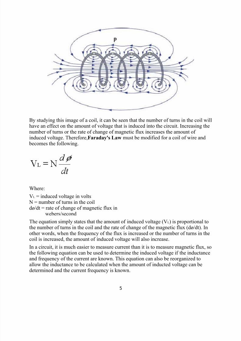
By studying this image of a coil, it can be seen that the number of turns in the coil willhave an effect on the amount of voltage that is induced into the circuit. Increasing thenumber of turns or the rate of change of magnetic flux increases the amount of induced voltage. Therefore,Faraday's Law must be modified for a coil of wire and
becomes the following.
Where:
VL = induced voltage in volts N = number of turns in the coildø/dt = rate of change of magnetic flux in
webers/second
The equation simply states that the amount of induced voltage (VL) is proportional tothe number of turns in the coil and the rate of change of the magnetic flux (dø/dt). Inother words, when the frequency of the flux is increased or the number of turns in the
coil is increased, the amount of induced voltage will also increase.In a circuit, it is much easier to measure current than it is to measure magnetic flux, sothe following equation can be used to determine the induced voltage if the inductanceand frequency of the current are known. This equation can also be reorganized toallow the inductance to be calculated when the amount of inducted voltage can bedetermined and the current frequency is known.
VL = the induced voltage in voltsL = the value of inductance in henriesdi/dt = the rate of change of current in amperes per second
Lenz's Law
Soon after Faraday proposed his law of induction, Heinrich Lenz developed a rule for determining the direction of the induced current in a loop. Basically, Lenz's law
states that an induced current has a direction such that its magnetic field opposesthe change in magnetic field that induced the current. This means that the currentinduced in a conductor will oppose the change in current that is causing the flux tochange. Lenz's law is important in understanding the property of inductive reactance,which is one of the properties measured in eddy current testing.
Inductive Reactance
The reduction of current flow in a circuit due to induction is called inductivereactance. By taking a closer look at a coil of wire and applying Lenz's law, it can beseen how inductance reduces the flow of current in the circuit. In the image below, thedirection of the primary current is shown in red, and the magnetic field generated by
the current is shown in blue. The direction of the magnetic field can be determined bytaking your right hand and pointing your thumb in the direction of the current. Your fingers will then point in the direction of the magnetic field. It can be seen that themagnetic field from one loop of the wire will cut across the other loops in the coil andthis will induce current flow (shown in green) in the circuit. According to Lenz's law,the induced current must flow in the opposite direction of the primary current. Theinduced current working against the primary current results in a reduction of currentflow in the circuit.
It should be noted that the inductive reactance will increase if the number of winds inthe coil is increased since the magnetic field from one coil will have more coils to
Similarly to resistance, inductive reactance reduces the flow of current in a circuit.However, it is possible to distinguish between resistance and inductive reactance in acircuit by looking at the timing between the sine waves of the voltage and current of the alternating current. In an AC circuit that contains only resistive components, thevoltage and the current will be in-phase, meaning that the peaks and valleys of their sine waves will occur at the same time. When there is inductive reactance present inthe circuit, the phase of the current will be shifted so that its peaks and valleys do notoccur at the same time as those of the voltage. This will be discussed in more detail inthe section on circuits.
Mutual Inductance(The Basis for Eddy Current Inspection)
The magnetic flux through a circuit can be related to the current in that circuit and thecurrents in other nearby circuits, assuming that there are no nearby permanentmagnets. Consider the following two circuits.
The magnetic field produced by circuit 1 will intersect the wire in circuit 2 and createcurrent flow. The induced current flow in circuit 2 will have its own magnetic fieldwhich will interact with the magnetic field of circuit 1. At some point P, the magnetic
field consists of a part due toi1 and a part due to i2. These fields are proportional to thecurrents producing them.
The coils in the circuits are labeled L1 and L2 and this term represents the self inductance of each of the coils. The values of L1 and L2 depend on the geometricalarrangement of the circuit (i.e. number of turns in the coil) and the conductivity of thematerial. The constant M, called themutual inductance of the two circuits, isdependent on the geometrical arrangement of both circuits. In particular, if the circuitsare far apart, the magnetic flux through circuit 2 due to the current i1 will be small andthe mutual inductance will be small. L2 and M are constants.
We can write the flux, B through circuit 2 as the sum of two parts.
B2 = L2i2 + i1M
An equation similar to the one above can be written for the flux through circuit 1.
B1
= L1
i1
+ i2
MThough it is certainly not obvious, it can be shown that the mutual inductance is thesame for both circuits. Therefore, it can be written as follows:
M1,2 = M2,1
How is mutual induction used in eddy currentinspection?
In eddy current inspection, the eddy currents aregenerated in the test material due to mutual induction. The test probe is basically a coil of wire through which
alternating current is passed. Therefore, when the probe is connected to an eddyscope instrument, it is basicallyrepresented by circuit 1 above. The second circuit can beany piece of conductive material.
When alternating current is passed through the coil, amagnetic field is generated in and around the coil. Whenthe probe is brought in close proximity to a conductivematerial, such as aluminum, the probe's changingmagnetic field generates current flow in the material. The
induced current flows in closed loops in planes perpendicular to the magnetic flux. They are named eddycurrents because they are thought to resemble the eddy currents that can be seenswirling in streams.
The eddy currents produce their own magnetic fields thatinteract with the primary magnetic field of the coil. Bymeasuring changes in the resistance and inductive
reactance of the coil, information can be gathered about the test material. Thisinformation includes the electrical conductivity and magnetic permeability of thematerial, the amount of material cutting through the coils magnetic field, and thecondition of the material (i.e. whether it contains cracks or other defects.) Thedistance that the coil is from the conductive material is called liftoff, and this distance
affects the mutual-inductance of the circuits. Liftoff can be used to makemeasurements of the thickness of nonconductive coatings, such as paint, that hold the
probe a certain distance from the surface of the conductive material.
It should be noted that if a sample is ferromagnetic, the magnetic flux is concentratedand strengthened despite opposing eddy current effects. The increase inductivereactance due to the magnetic permeability of ferromagnetic materials makes it easyto distinguish these materials from nonferromagnetic materials.
In the applet below, the probe and the sample are shown in cross-section. The boxesrepresent the cross-sectional area of a group of turns in the coil. The liftoff distance
and the drive current of the probe can be varied to see the effects of the sharedmagnetic field. The liftoff value can be set to 0.1 or less and the current value can bevaried from 0.01 to 1.0. The strength of the magnetic field is shown by the darkness of the lines.
Circuits and Phase
A circuit can be thought of as a closed path in which current flows through thecomponents that make up the circuit. The current (i) obeys Ohm's Law, which isdiscussed on the page oncurrent flow. The simple circuit below consists of a voltagesource (in this case an alternating current voltage source) and a resistor. The graph
below the circuit diagram shows the value of the voltage and the current for this
circuit over a period of time. This graph shows one complete cycle of an alternatingcurrent source. From the graph, it can be seen that as the voltage increases, the currentdoes the same. The voltage and the current are said to be "in-phase" since their zero,
peak, and valley points occur at the same time. They are also directly proportional toeach other.
In the circuit below, the resistive component has been replaced with an inductor.When inductance is introduced into a circuit, the voltage and the current will be "out-of-phase," meaning that the voltage and current do not cross zero, or reach their peaksand valleys at the same time. When a circuit has an inductive component, the current(iL) will lag the voltage by one quarter of a cycle. One cycle is often referred to as360o, so it can be said that the current lags the voltage by 90o.
This phase shift occurs because the inductive reactance changes with changingcurrent. Recall that it is the changing magnetic field caused by a changing current that
produces inductive reactance. When the change in current is greatest, inductivereactance will be the greatest, and the voltage across the inductor will be the highest.When the change in current is zero, the inductive reactance will be zero and thevoltage across the inductor will be zero. Be careful not to confuse the amount of current with the amount of change in the current. Consider the points where thecurrent reaches it peak amplitude and changes direction in the graph below (0o, 180o,and 360o). As the current is changing directions, there is a split second whenthe change in current is zero. Since the change in current is zero, no magnetic fieldis generated to produce the inductive reactance. When the inductive reactance is zero,the voltage across the inductor is zero.
The resistive and inductive components are of primary interest in eddy current testingsince the test probe is basically a coil of wire, which will have both resistance andinductive reactance. However, there is a small amount of capacitance in the circuits so
a mention is appropriate. This simple circuit below consists of an alternating currentvoltage source and a capacitor. Capacitance in a circuit caused the current (ic) to leadthe voltage by one quarter of a cycle (90o current lead).
When there is both resistance and inductive reactance (and/or capacitance) in a circuit,the combined opposition to current flow is known as impedance. Impedance will bediscussed more on the next page.