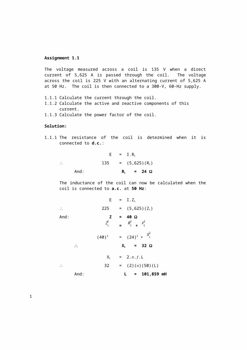
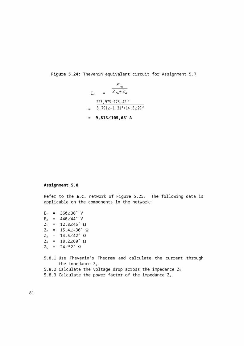
Assignment 1.1 The voltage measured across a coil is 135 V when a direct current of 5,625 A is passed through the coil. The voltage across the coil is 225 V with an alternating current of 5,625 A at 50 Hz. The coil is then connected to a 300-V, 60-Hz supply. 1.1.1 Calculate the current through the coil. 1.1.2 Calculate the active and reactive components of this current. 1.1.3 Calculate the power factor of the coil. Solution: 1.1.1 The resistance of the coil is determined when it is connected to d.c.: E = I.R L 135 = (5,625)(R L ) And: R L = 24 The inductance of the coil can now be calculated when the coil is connected to a.c. at 50 Hz: E = I.Z L 225 = (5,625)(Z L ) And: Z = 40 Z L 2 = R L 2 + X L 2 (40) 2 = (24) 2 + X L 2 X L = 32 X L = 2...L 32 = (2)()(50)(L) And: L = 101,859 mH 1
Transcript
Assignment 1.1
The voltage measured across a coil is 135 V when a direct current of 5,625 A is passed through the coil. The voltage across the coil is 225 V with an alternating current of 5,625 A at 50 Hz. The coil is then connected to a 300-V, 60-Hz supply.
1.1.1 Calculate the current through the coil.1.1.2 Calculate the active and reactive components of this current.1.1.3 Calculate the power factor of the coil.
Solution:
1.1.1 The resistance of the coil is determined when it is connected to d.c.:
E = I.RL
135= (5,625)(RL)
And: RL= 24
The inductance of the coil can now be calculated when the coil is connected to a.c. at 50 Hz:
E = I.ZL
225= (5,625)(ZL)
And: Z= 40
ZL2 = RL
2 + X L
2
(40)2 = (24)2 + X L2
XL= 32
XL = 2...L
32 = (2)()(50)(L)
And: L = 101,859 mH
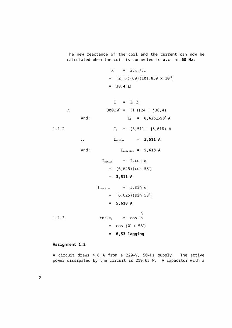
The new reactance of the coil and the current can now be calculated when the coil is connected to a.c. at 60 Hz:
XL = 2...L
= (2)()(60)(101,859 x 103)
= 38,4
1
E = IL.ZL
3000= (IL)(24 + j38,4)
And: IL= 6,62558 A
1.1.2 IL = (3,511 j5,618) A
Iactive = 3,511 A
And: Ireactive = 5,618 A
Iactive = I.cos
= (6,625)(cos 58)
= 3,511 A
Ireactive = I.sin
= (6,625)(sin 58)
= 5,618 A
1.1.3 cos L= cosI L
V L
= cos (0 + 58)
= 0,53 lagging
Assignment 1.2
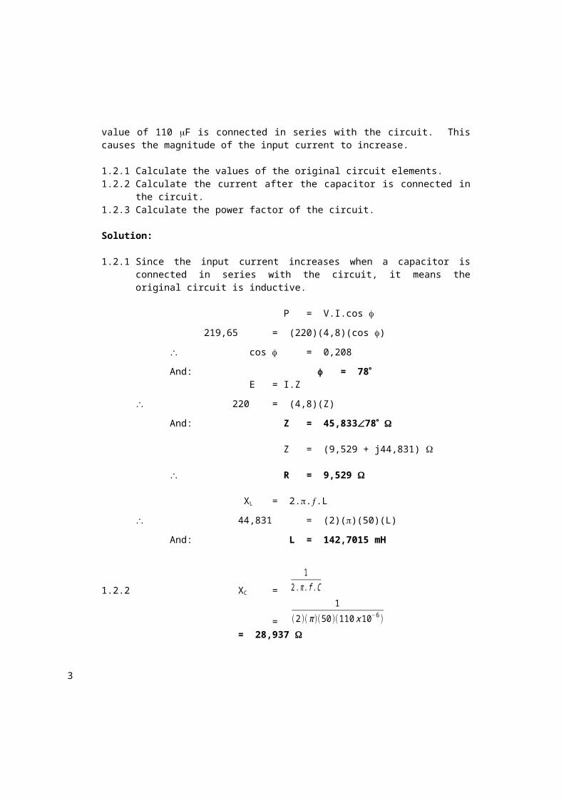
A circuit draws 4,8 A from a 220-V, 50-Hz supply. The active power dissipated by the circuit is 219,65 W. A capacitor with a value of 110 F is connected in series with the circuit. This causes the magnitude of the input current to increase.
1.2.1 Calculate the values of the original circuit elements.1.2.2 Calculate the current after the capacitor is connected in the circuit.1.2.3 Calculate the power factor of the circuit.
Solution:
1.2.1 Since the input current increases when a capacitor is connected in series with the circuit, it means the original circuit is inductive.
P = V.I.cos
219,65= (220)(4,8)(cos )
cos = 0,208
2
And: = 78 E = I.Z
220= (4,8)(Z)
And: Z= 45,83378
Z = (9,529 + j44,831)
R = 9,529
XL = 2...L
44,831 = (2)()(50)(L)
And: L = 142,7015 mH
1.2.2 XC =
12. π . f .C
=
1
(2)( π )(50)(110 x 10−6 )= 28,937
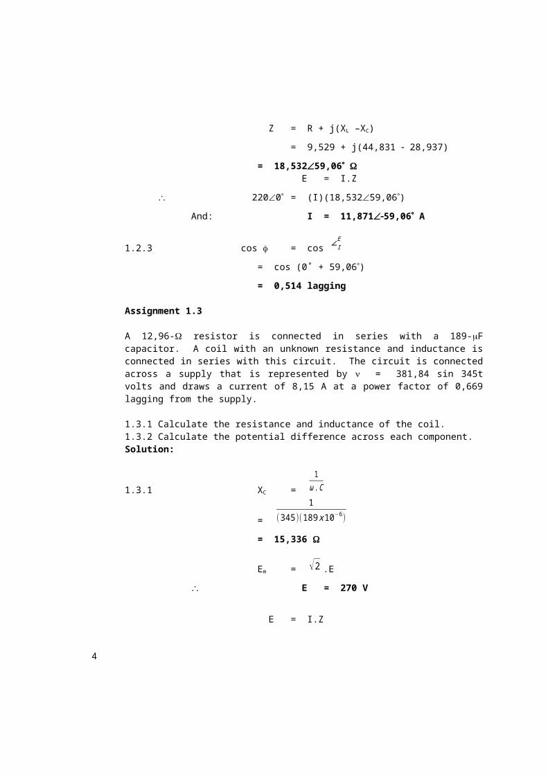
Z = R + j(XL –XC)
= 9,529 + j(44,831 28,937)
= 18,53259,06 E = I.Z
2200= (I)(18,53259,06)
And: I= 11,87159,06 A
1.2.3 cos = cos ∠IE
= cos (0˚ + 59,06)
= 0,514 lagging
Assignment 1.3
A 12,96- resistor is connected in series with a 189-F capacitor. A coil with an unknown resistance and inductance is connected in series with this circuit. The circuit is connected across a supply that is represented by = 381,84 sin 345t volts and draws a current of 8,15 A at a power factor of 0,669 lagging from the supply.
1.3.1 Calculate the resistance and inductance of the coil.1.3.2 Calculate the potential difference across each component.
3
Solution:
1.3.1 XC =
1ω .C
=
1
(345 )(189 x 10−6 )
= 15,336
Em = √2 .E
E= 270 V
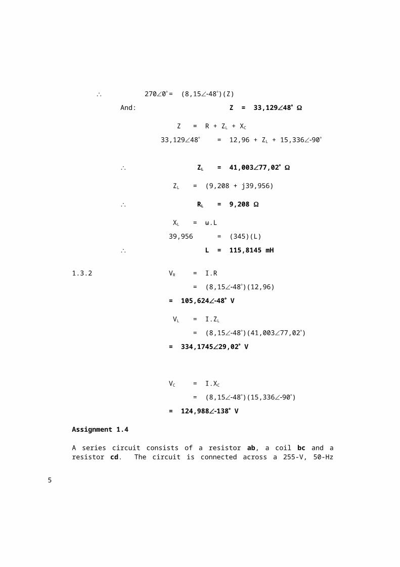
E = I.Z
2700= (8,1548)(Z)
And: Z = 33,12948
Z = R + ZL + XC
33,12948 = 12,96 + ZL + 15,33690
ZL= 41,00377,02
ZL = (9,208 + j39,956)
RL= 9,208
XL = ω.L
39,956 = (345)(L)
L = 115,8145 mH
1.3.2 VR = I.R
= (8,1548)(12,96)
= 105,62448 V
VL = I.ZL
= (8,1548)(41,00377,02)
= 334,174529,02 V
VC = I.XC
4
= (8,1548)(15,33690)
= 124,988138 V
Assignment 1.4
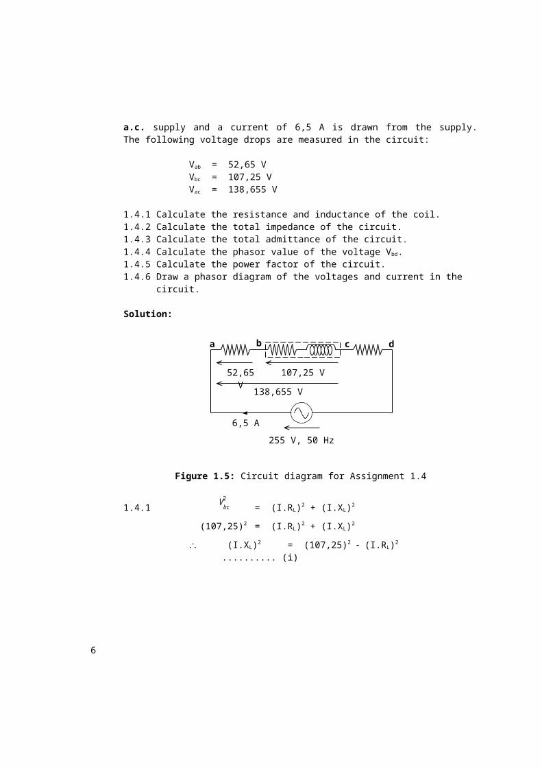
A series circuit consists of a resistor ab, a coil bc and a resistor cd. The circuit is connected across a 255-V, 50-Hz a.c. supply and a current of 6,5 A is drawn from the supply. The following voltage drops are measured in the circuit:
Vab = 52,65 VVbc = 107,25 VVac = 138,655 V
1.4.1 Calculate the resistance and inductance of the coil.1.4.2 Calculate the total impedance of the circuit.1.4.3 Calculate the total admittance of the circuit.1.4.4 Calculate the phasor value of the voltage Vbd.1.4.5 Calculate the power factor of the circuit.1.4.6 Draw a phasor diagram of the voltages and current in the circuit.
Solution:
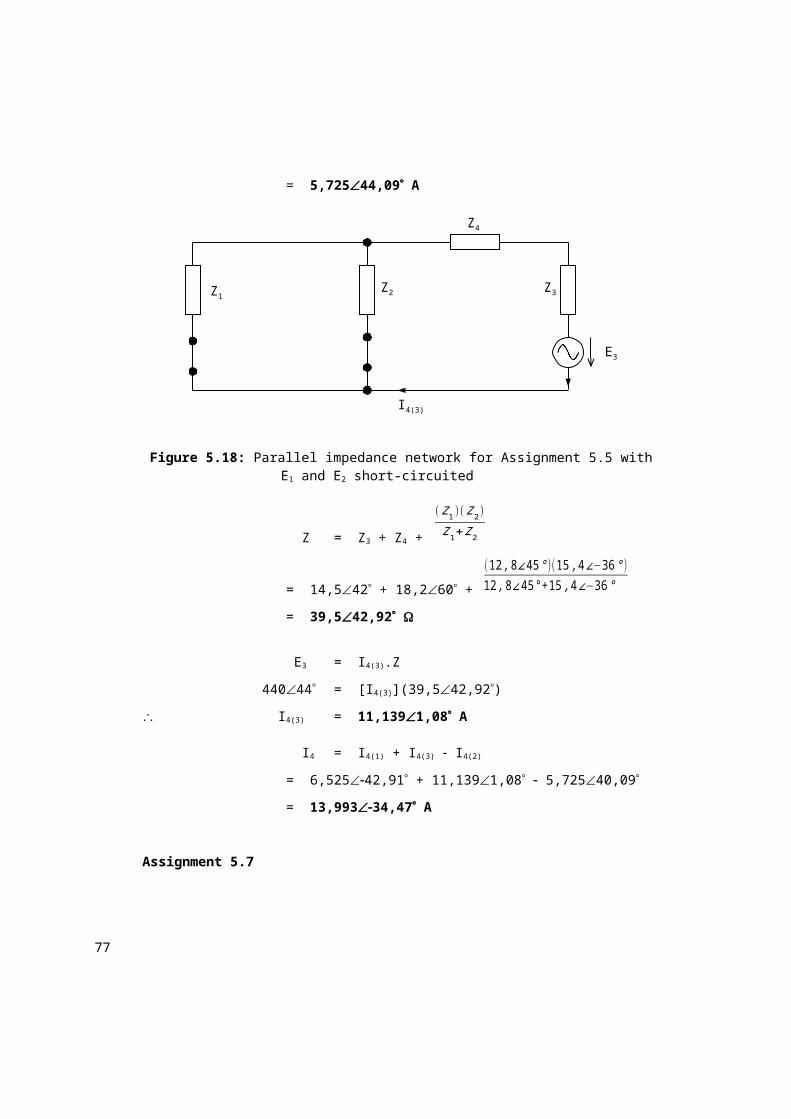
Figure 1.5: Circuit diagram for Assignment 1.4
1.4.1 V bc2
= (I.RL)2 + (I.XL)2
(107,25)2= (I.RL)2 + (I.XL)2
(I.XL)2 = (107,25)2 (I.RL)2 .......... (i)
dcba
255 V, 50 Hz
6,5 A
138,655 V
107,25 V52,65 V
5
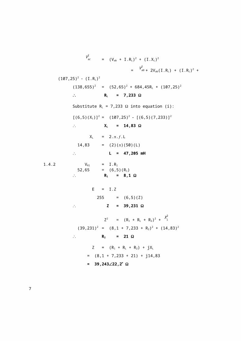
V ac2
= (Vab + I.RL)2 + (I.XL)2
= V ab2
+ 2Vab(I.RL) + (I.RL)2 + (107,25)2 (I.RL)2
(138,655)2= (52,65)2 + 684,45RL + (107,25)2
RL= 7,233
Substitute RL = 7,233 into equation (i):
[(6,5)(XL)]2 = (107,25)2 [(6,5)(7,233)]2
XL= 14,83
XL = 2...L
14,83= (2)()(50)(L)
L = 47,205 mH
1.4.2 VR1 = I.R1
52,65= (6,5)(R1) R1 = 8,1
E = I.Z
255 = (6,5)(Z)
Z= 39,231
Z2= (R1 + RL + R2)2 + X L2
(39,231)2= (8,1 + 7,233 + R2)2 + (14,83)2
R2 = 21
Z = (R1 + RL + R2) + jXL
= (8,1 + 7,233 + 21) + j14,83
= 39,24322,2
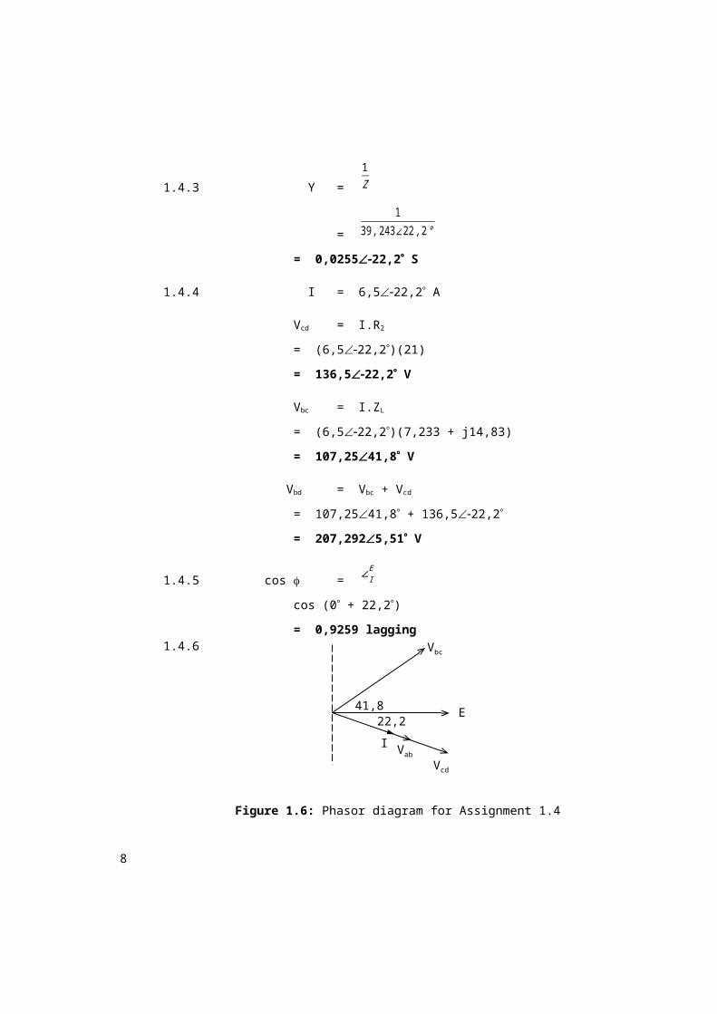
1.4.3 Y =
1Z
=
139 ,243∠22 ,2 °
= 0,025522,2 S
6
1.4.4 I = 6,522,2 A
Vcd = I.R2
= (6,522,2)(21)
= 136,522,2 V
Vbc = I.ZL
= (6,522,2)(7,233 + j14,83)
= 107,2541,8 V
Vbd = Vbc + Vcd
= 107,2541,8 + 136,522,2
= 207,2925,51 V
1.4.5 cos = ∠IE
cos (0 + 22,2)
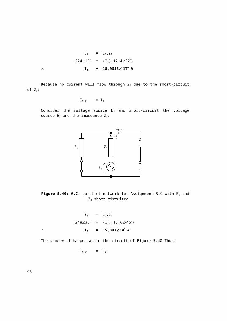
= 0,9259 lagging1.4.6
Figure 1.6: Phasor diagram for Assignment 1.4
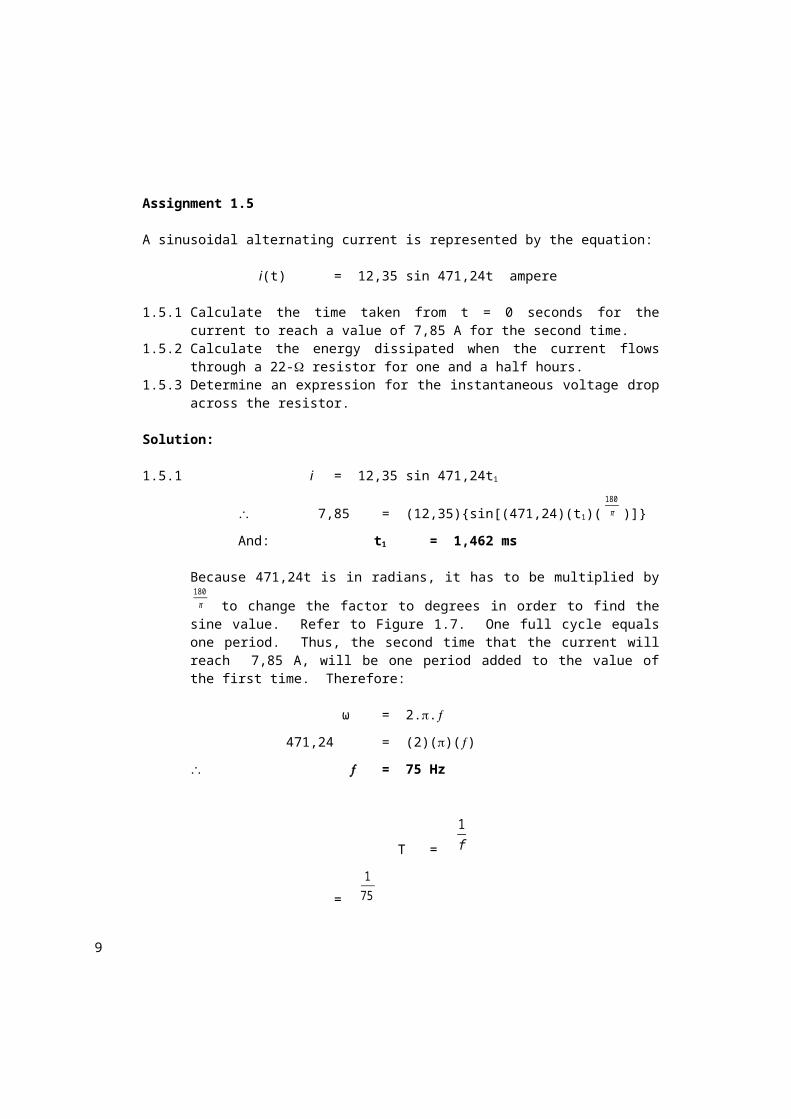
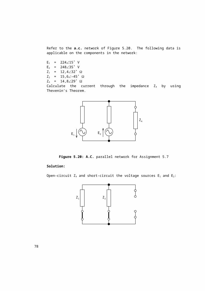
Assignment 1.5
A sinusoidal alternating current is represented by the equation:
i(t) = 12,35 sin 471,24t ampere
1.5.1 Calculate the time taken from t = 0 seconds for the current to reach a value of 7,85 A for the second time.
1.5.2 Calculate the energy dissipated when the current flows through a 22- resistor for one and a half hours.
1.5.3 Determine an expression for the instantaneous voltage drop across the resistor.
Solution:
I Vab
Vcd
Vbc
E22,2
41,8
7
1.5.1 i = 12,35 sin 471,24t1
7,85= (12,35){sin[(471,24)(t1)(180π )]}
And: t1 = 1,462 ms
Because 471,24t is in radians, it has to be multiplied by 180π to change
the factor to degrees in order to find the sine value. Refer to Figure 1.7. One full cycle equals one period. Thus, the second time that the current will reach 7,85 A, will be one period added to the value of the first time. Therefore:
ω = 2..
471,24= (2)()()
= 75 Hz
T =
1f
=
175
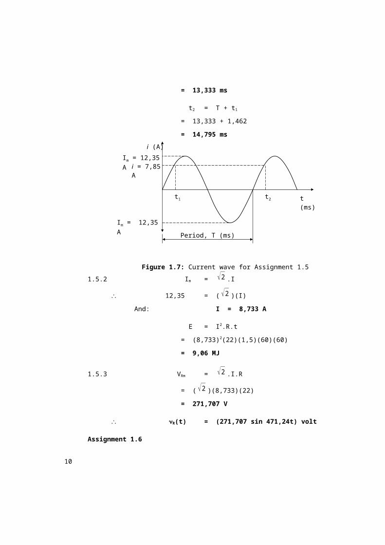
= 13,333 ms
t2 = T + t1
= 13,333 + 1,462
= 14,795 ms
Figure 1.7: Current wave for Assignment 1.5
Im = 12,35 A
i = 7,85 AIm = 12,35 A
Period, T (ms)
t2t1 t (ms)
i (A)
8
1.5.2 Im = √2 .I
12,35= (√2 )(I)
And: I= 8,733 A
E = I2.R.t
= (8,733)2(22)(1,5)(60)(60)
= 9,06 MJ
1.5.3 VRm = √2 .I.R
= (√2 )(8,733)(22)
= 271,707 V
R(t) = (271,707 sin 471,24t) volt
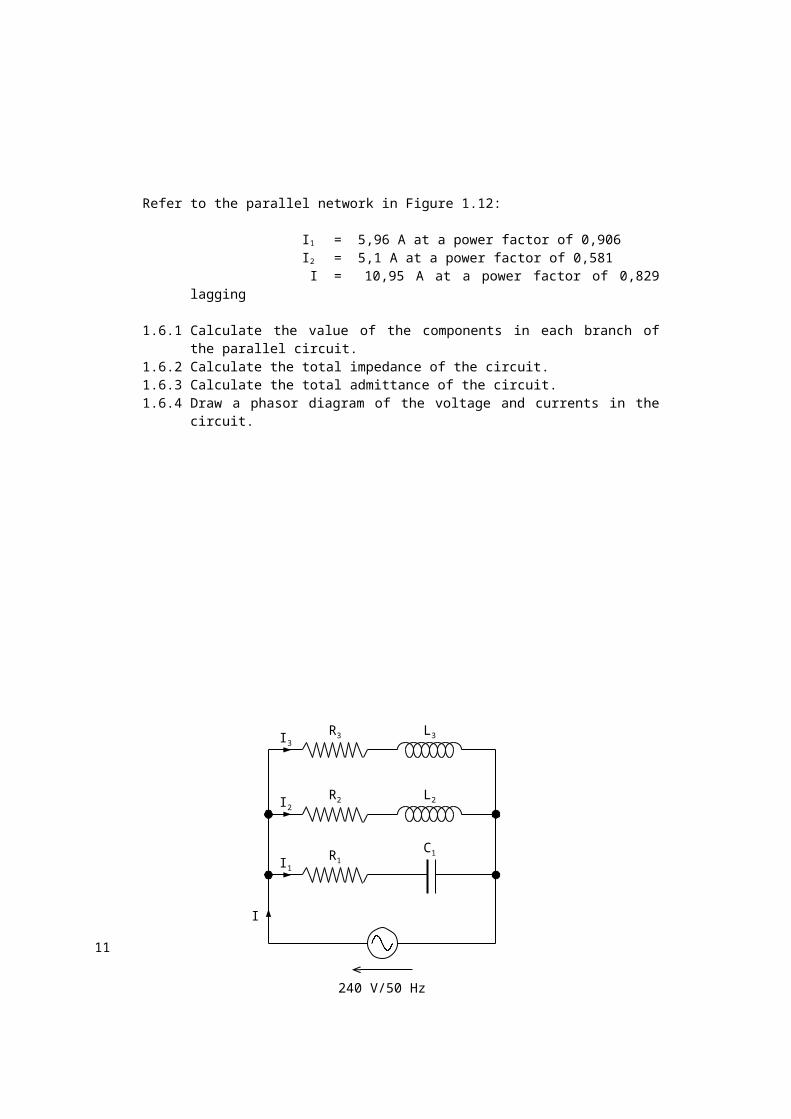
Assignment 1.6
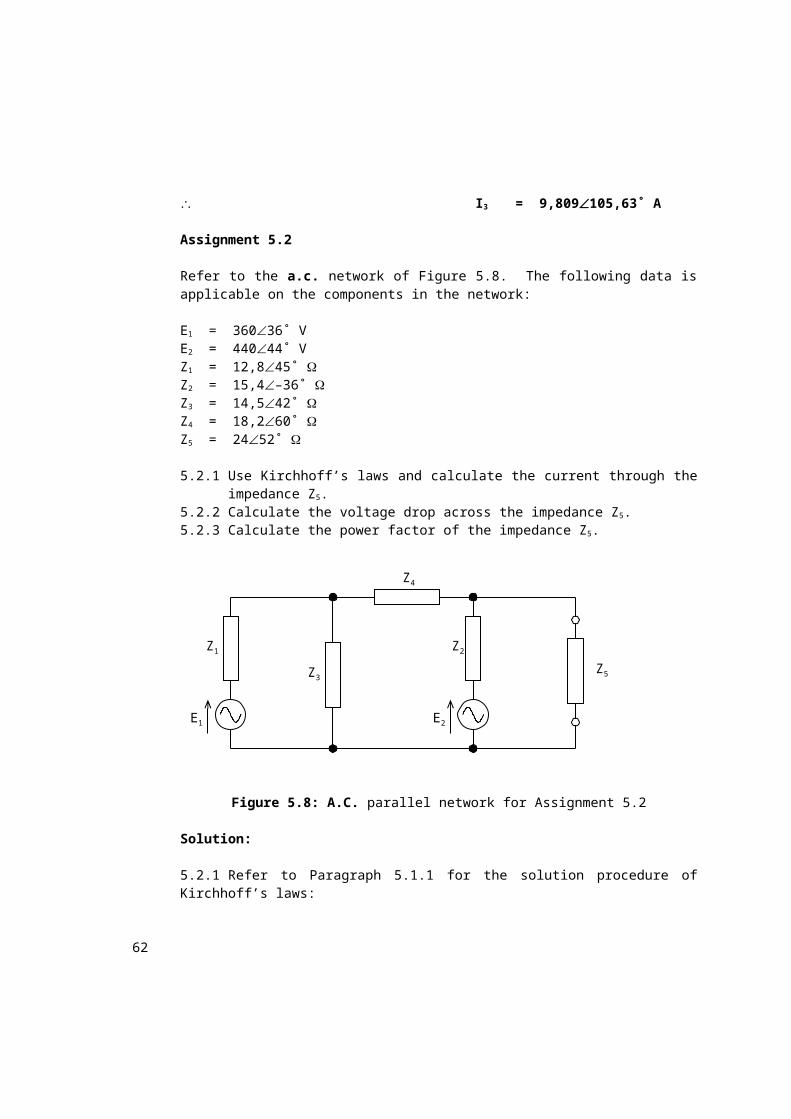
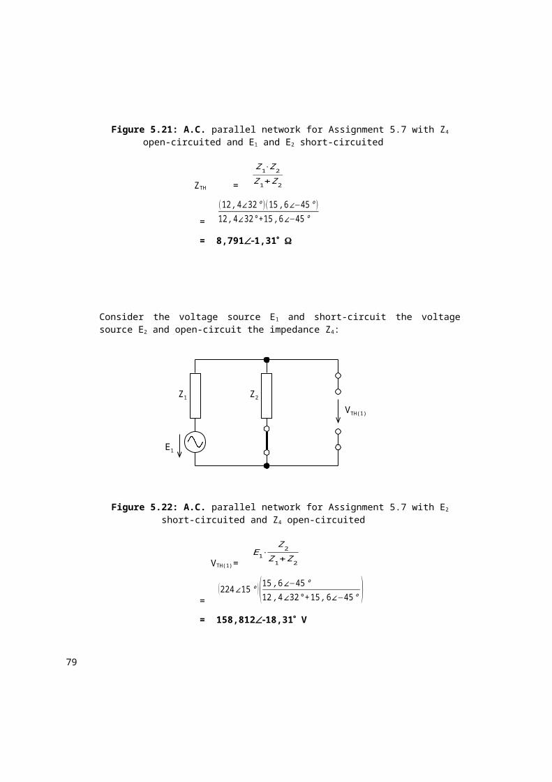
Refer to the parallel network in Figure 1.12:
I1 = 5,96 A at a power factor of 0,906 I2 = 5,1 A at a power factor of 0,581 I = 10,95 A at a power factor of 0,829 lagging
1.6.1 Calculate the value of the components in each branch of the parallel circuit.
1.6.2 Calculate the total impedance of the circuit.1.6.3 Calculate the total admittance of the circuit.1.6.4 Draw a phasor diagram of the voltage and currents in the circuit.
9
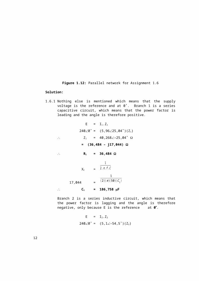
Figure 1.12: Parallel network for Assignment 1.6
Solution:
1.6.1 Nothing else is mentioned which means that the supply voltage is the reference and at 0˚. Branch 1 is a series capacitive circuit, which means that the power factor is leading and the angle is therefore positive.
E = I1.Z1
2400˚ = (5,9625,04˚)(Z1)
Z1 = 40,268–25,04˚
= (36,484 – j17,044)
R1 = 36,484
XC =
12. π . f .C
17,044=
1(2)( π )(50)(C1)
C1 = 186,758 F
C1R1
L2R2
L3R3
I
I3
I2
I1
240 V/50 Hz
10
Branch 2 is a series inductive circuit, which means that the power factor is lagging and the angle is therefore negative, only because E is the reference at 0.
E = I2.Z2
2400˚ = (5,1–54,5˚)(Z2)
Z2 = 47,05954,5˚
= (27,327 + j38,311)
R2 = 27,327
XL = 2...L2
38,311= (2)()(50)(L2)
L2 = 121,95 mH
I = I1 + I2 + I3
10,95–34˚ = 5,9625,04˚ + 5,1–54,5˚ + I3
I3 = 4,551–80,94˚ A
E = I1.Z1
2400˚ = (4,551–80,94˚)(Z3)
Z3 = 52,73680,94˚
= (8,304 + j52,078) R3 = 8,304
XL = 2...L
52,078= (2)()(50)(L)
L3 = 165,769 mH
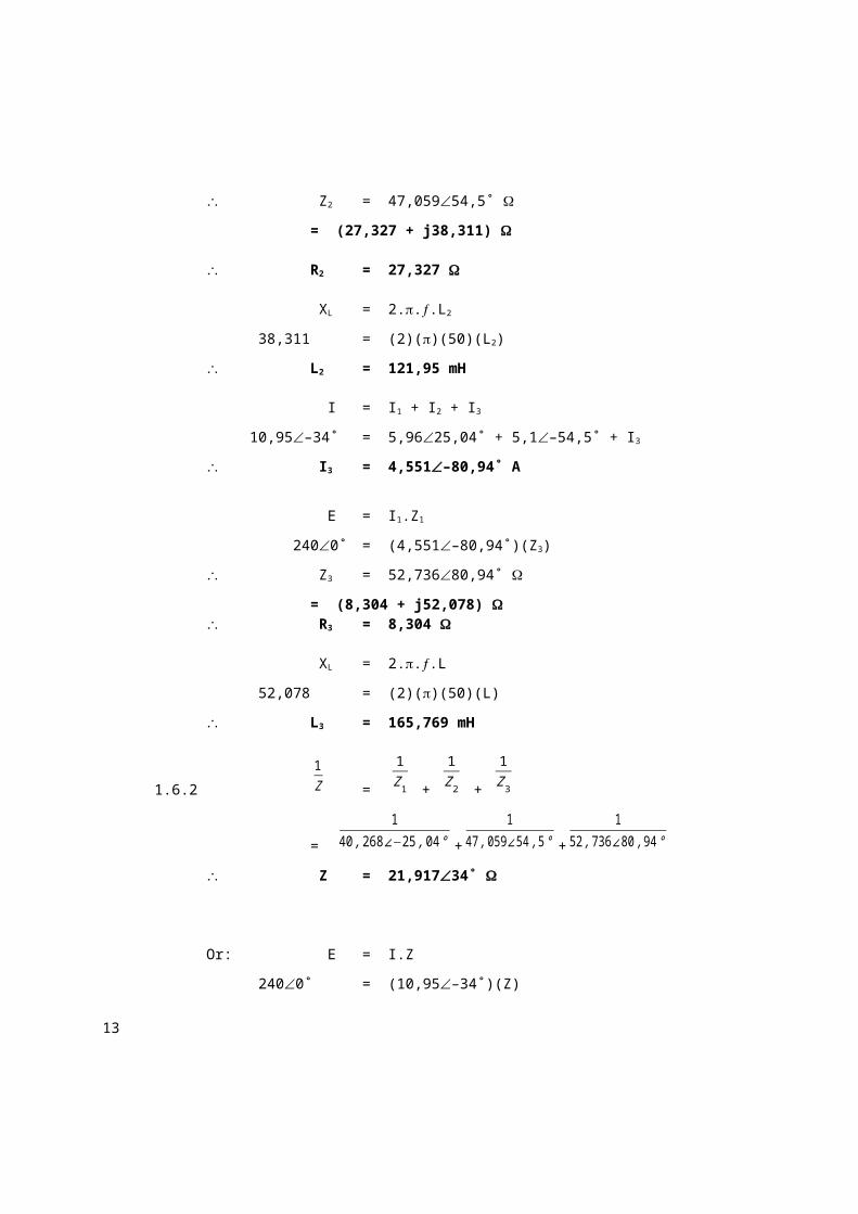
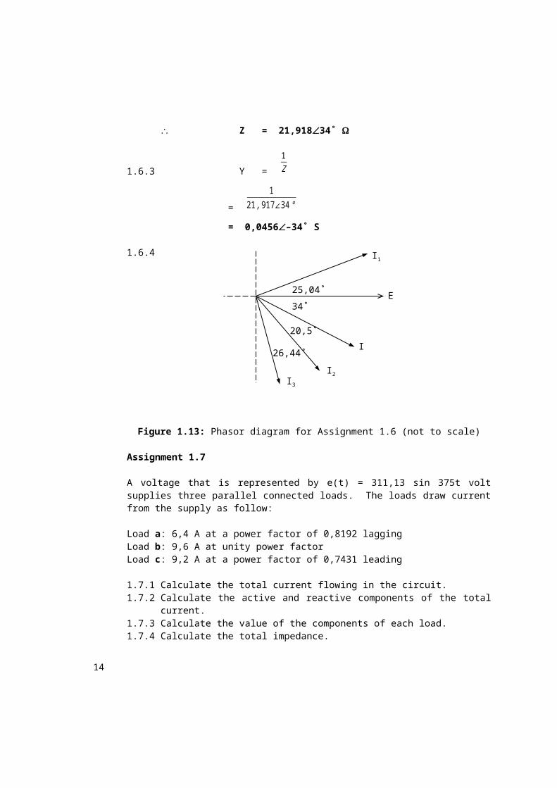
1.6.2
1Z =
1Z1 +
1Z2 +
1Z3
=
140 ,268∠−25 ,04 ° +
147 ,059∠54 ,5 ° +
152 ,736∠ 80 ,94 °
Z = 21,91734˚
Or: E = I.Z
11
2400˚ = (10,95–34˚)(Z)
Z= 21,91834˚
1.6.3 Y =
1Z
=
121 ,917∠34 °
= 0,0456–34˚ S
1.6.4
Figure 1.13: Phasor diagram for Assignment 1.6 (not to scale)
Assignment 1.7
A voltage that is represented by e(t) = 311,13 sin 375t volt supplies three parallel connected loads. The loads draw current from the supply as follow:
Load a: 6,4 A at a power factor of 0,8192 laggingLoad b: 9,6 A at unity power factorLoad c: 9,2 A at a power factor of 0,7431 leading
1.7.1 Calculate the total current flowing in the circuit.1.7.2 Calculate the active and reactive components of the total current.1.7.3 Calculate the value of the components of each load.1.7.4 Calculate the total impedance.1.7.5 Calculate the overall power factor of the circuit.1.7.6 If these loads were to be connected in series across the same supply,
what would be the current and overall power of the series circuit?
Solution:
1.7.1 I = I1 + I2 + I3
E
26,44˚
20,5˚
34˚
25,04˚
I3I2
I
I1
12
= 6,4–35˚ + 9,60˚ + 9,242˚
= 21,82156,54˚ A
1.7.2 I = (21,6795 + j2,485) A
Iactive = 21,6795 A
And: Ireactive = 2,485 A
1.7.3 Em = √2 .E
E =
311 ,13
√2
= 220 V
E = Ia.Za
2200˚ = (6,4–35˚)(Za)
Za = 34,37535˚
= (28,158 + j19,717) Ra = 28,158
XL = ω.La
19,717= (375)(La)
La = 52,579 mH
E = Ib.Zb
2200˚ = (9,6)(Zb)
Zb = 22,917
Rb = 22,917
E = Ic.Zc
2200˚ = (9,242˚)(Zc)
Zc = 23,913–42˚
= (17,771 – j16,001) Rc= 17,771
XC =
1ω .C
13
16,001=
1(375 )(Cc )
Cc = 166,656 F
1.7.4
1Z =
1Z1 +
1Z2 +
1Z3
=
134 ,375∠35 ° +
122 ,917 +
123 ,913∠−42 °
Z = 10,082–6,54˚
1.7.5 cos = cos ∠IE
= cos (0 6,54˚)
= 0,9935 leading
1.7.6 Z = Z1 + Z2 + Z3
= 34,37535˚ + 22,917 + 23,913–42˚
= 68,9463,09˚
E = I.Z
2200˚ = (I)(68,9463,09˚)
I = 3,191–3,09˚ A
cos = cos ∠IE
= cos (0 3,09˚)
= 0,99855 lagging
Assignment 1.8
A coil is connected in parallel with an 18,75- resistor across a 50-Hz supply. The currents through the coil and resistor are 6,4 A and 4,8 A respectively. The current drawn from the supply by the circuit is 9,6 A.
14
1.8.1 Calculate the resistance and inductance of the coil.1.8.2 Calculate the power factor of the circuit.1.8.3 Draw a phasor diagram of the voltage and currents in the circuit.
Solution:
1.8.1
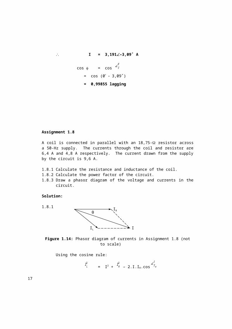
Figure 1.14: Phasor diagram of currents in Assignment 1.8 (not to scale)
Using the cosine rule:
IL2
= I2 + IR2
– 2.I.IR.cos∠I R
I
(6,4)2 = (9,6)2 + (4,8)2 – (2)(9,6)(4,8)(cos θ)
cos θ = 0,8056
And: θ = 36,34˚
The circuit is inductive and the overall power factor will therefore be lagging.
I = IL + IR
9,6–36,34˚ = IL + 4,80˚
IL = 6,4–62,73˚ A
E = I.Z
= (4,8)(18,75)
= 90 V
E = I.ZL
900˚= (6,4–62,73˚)(ZL)
ZL = 14,062562,73˚
= (6,443 + j12,5)
θ
IL I
IR
15
RL = 6,443
XL = 2...L
12,5= (2)()(50)(L)
L = 39,789 mH
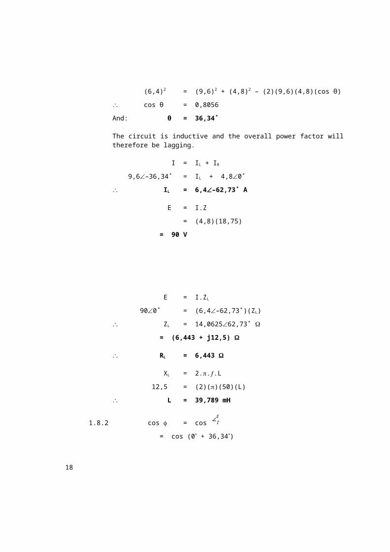
1.8.2 cos = cos ∠IE
= cos (0 + 36,34)
= 0,8055 lagging
1.8.3
Assignment 1.9
A single-phase a.c. parallel network consists of three branches with the current flowing in each branch represented by the equations:
i1(t) = 21,3 cos (ωt – π
1,5 ) A
i2(t) = 27,4 sin (ωt + π6 ) A
i3(t) = 18,6 sin (ωt + π3 ) A
The circuit is connected across a supply that is represented by the equation:
e(t) = 311,127 sin (315t + 0,085) V
1.9.1 Calculate the total current drawn from the supply expressing it in the same form as the branch currents.
1.9.2 Calculate the total admittance in the circuit.1.9.3 Calculate the overall power factor of the circuit.1.9.4 Draw the equivalent circuit for the parallel network.1.9.5 Calculate the total current drawn from the supply and the overall
power factor of the circuit if these impedances are connected in series across the same supply.
Solution:
26,39
36,34E
IL
I
IR
16
1.9.1 Im1 = 21,3(– 120˚ + 90˚) A
= 21,3–30˚ A
Im2 = 27,430˚ A
Im3 = 18,660˚ A
Im = I1 + I2 + I3
= 21,3–30˚ + 27,430˚ + 18,660˚
= 54,92520,41˚ A
i(t) = 54,925 sin (ωt + 0,356) A
1.9.2 Em = Im.Z
311,12715,3˚ = (54,92520,41˚)(Z)
Z = 5,665–5,11˚
Y =
1Z
=
15 ,665∠−5 ,11°
= 0,17655,11˚ S
1.9.3 cos = cos ∠IE
= cos (15,3˚ – 20,41˚)
= 0,996 leading
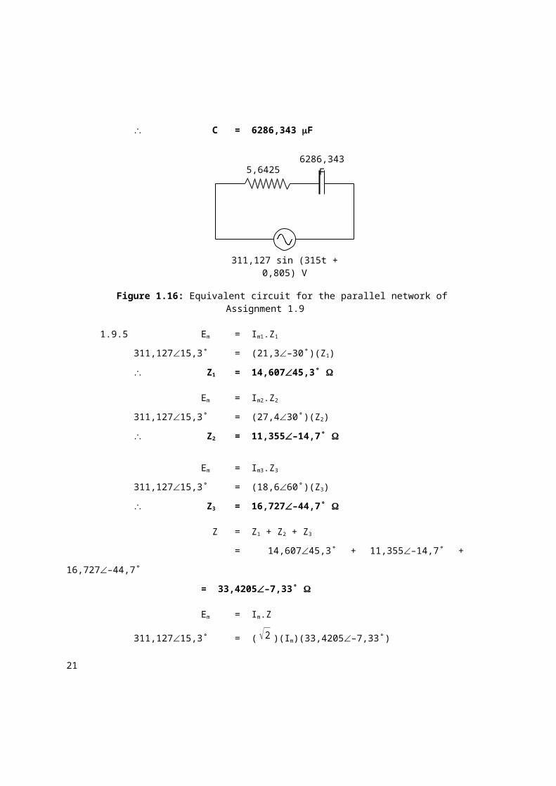
1.9.4 Z = (5,6425 – j0,505)
XC =
1ω .C
0,505=
1(315 )(C )
C = 6286,343 F
17
Figure 1.16: Equivalent circuit for the parallel network of Assignment 1.9
1.9.5 Em = Im1.Z1
311,12715,3˚ = (21,3–30˚)(Z1)
Z1 = 14,60745,3˚
Em = Im2.Z2
311,12715,3˚ = (27,430˚)(Z2)
Z2 = 11,355–14,7˚
Em = Im3.Z3
311,12715,3˚ = (18,660˚)(Z3)
Z3 = 16,727–44,7˚
Z = Z1 + Z2 + Z3
= 14,60745,3˚ + 11,355–14,7˚ + 16,727–44,7˚
= 33,4205–7,33˚
Em = Im.Z
311,12715,3˚ = (√2 )(Im)(33,4205–7,33˚)
Im = 6,58322,63˚ A
cos = cos ∠IE
= cos (15,3˚ – 22,63˚)
= 0,9918 leading
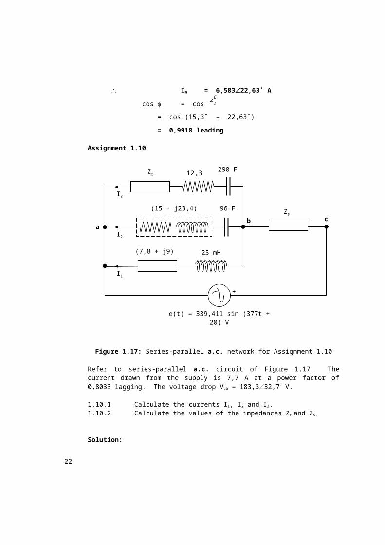
Assignment 1.10
311,127 sin (315t + 0,805) V
6286,343 F5,6425
I3
I2
I1
bZs
Zx 12,3 290 F
c
25 mH(7,8 + j9)
(15 + j23,4) 96 F
a
18
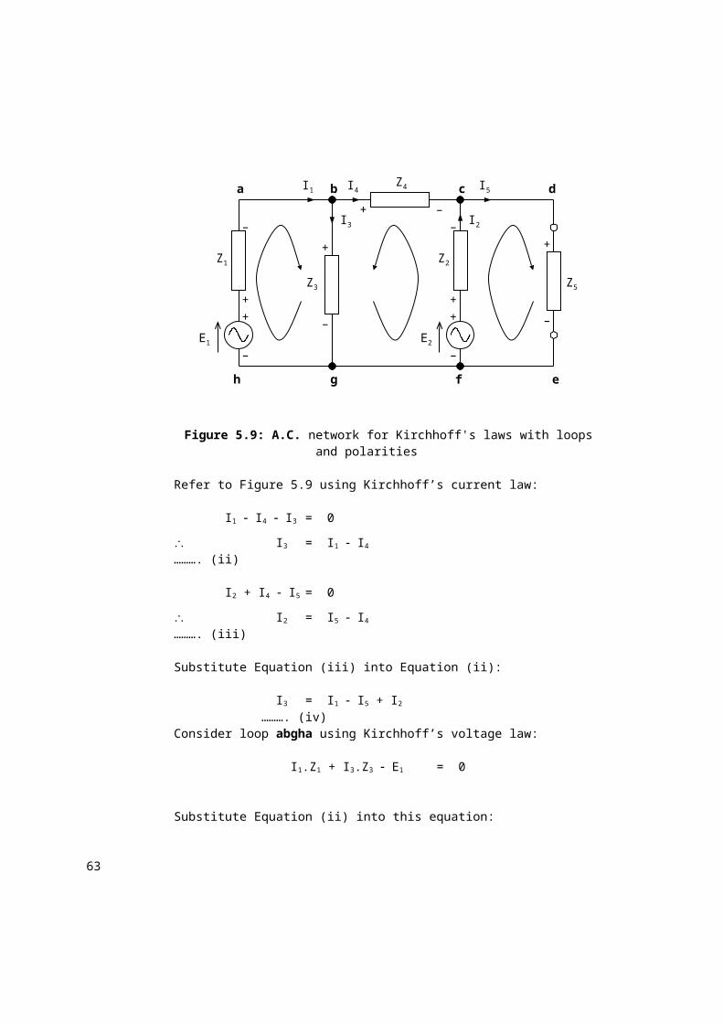
Figure 1.17: Series-parallel a.c. network for Assignment 1.10
Refer to series-parallel a.c. circuit of Figure 1.17. The current drawn from the supply is 7,7 A at a power factor of 0,8033 lagging. The voltage drop Vcb
= 183,332,7 V.
1.10.1 Calculate the currents I1, I2 and I3.1.10.2 Calculate the values of the impedances Zx and Zs.
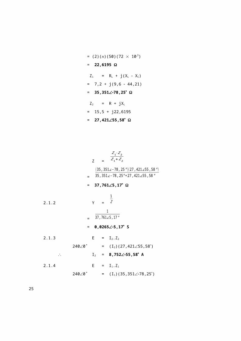
A coil of (7,2 + j9,6) is connected in series with a capacitor of 72 F. Another series circuit consists of a 15,5- resistor and a 72-mH inductor. The two circuits are then connected in parallel across a 240-V, 50-Hz supply.
2.1.1 Calculate the impedance of the circuit2.1.2 Calculate the admittance of the circuit.2.1.3 Calculate the current through the inductor.2.1.4 Calculate the current through the coil.2.1.5 Do the necessary calculations and draw the power triangle.2.1.6 Calculate the voltage drops across the inductor and the resistor.
20
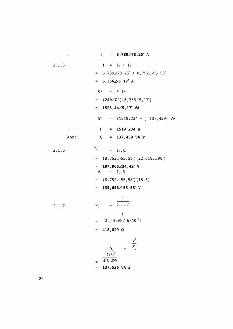
2.1.7 Calculate the power factor of the circuit if a capacitor of 7,6 F is connected in parallel with the circuit to improve the power factor.
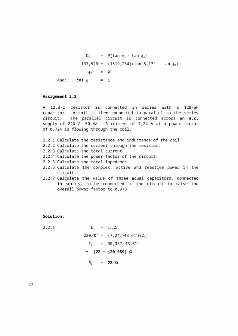
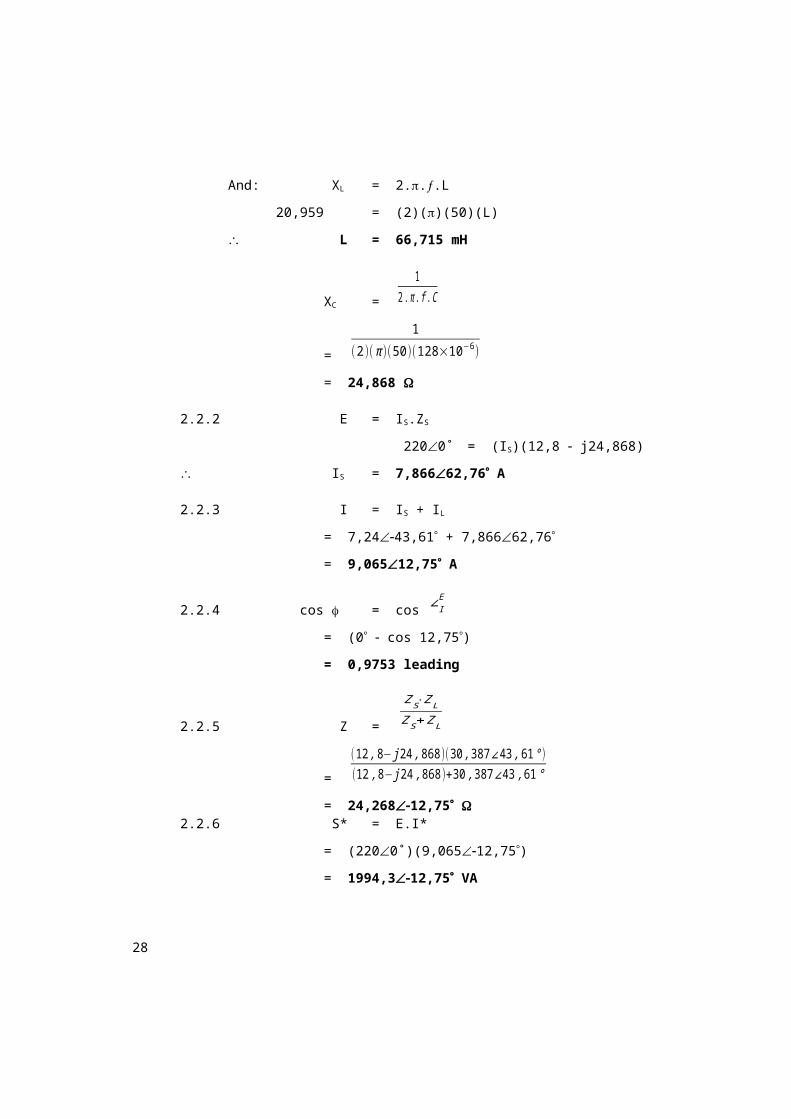
A 12,8- resistor is connected in series with a 128-F capacitor. A coil is then connected in parallel to the series circuit. The parallel circuit is connected across an a.c. supply of 220-V, 50-Hz. A current of 7,24 A at a power factor of 0,724 is flowing through the coil.
2.2.1 Calculate the resistance and inductance of the coil.2.2.2 Calculate the current through the resistor.2.2.3 Calculate the total current.2.2.4 Calculate the power factor of the circuit.2.2.5 Calculate the total impedance.2.2.6 Calculate the complex, active and reactive power in the circuit.2.2.7 Calculate the value of three equal capacitors, connected in series, to
be connected in the circuit to raise the overall power factor to 0,978.
Four elements are connected in parallel across a sinusoidal a.c. voltage supply that is represented by:
e(t) = 339,41 sin (314t π3 ) volt
The current drawn from the supply is represented by:
i(t) = 17,35 cos (314t 82,5˚) ampereThe instantaneous values of the current flowing through three of the elements are represented by:
i1(t) = 7,35 sin (314t +π
7,5 ) ampere
i2(t) = 8,1 sin (314t +π45 ) ampere
i3(t) = 7,1 sin (314t +π15 ) ampere
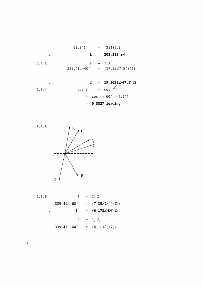
2.3.1 Determine the expression for the current of the fourth element.2.3.2 Calculate the component values of the fourth element.2.3.3 Calculate the impedance of the circuit.2.3.4 Calculate the power factor of the circuit.2.3.5 Draw a phasor diagram of the voltage and currents in the circuit.
25
2.3.6 If these impedances were connected in series, what would be the current flowing in the circuit?
2.3.7 Calculate the power factor of the series circuit.2.3.8 Calculate the value of a capacitor bank to be connected in parallel to
the parallel circuit to raise the overall power factor to 0,809 lagging.
Solution:
2.3.1 Im = Im1 + Im2 + Im3 + Im4
17,357,5 = 7,3524 + 8,14 + 7,112 + Im4
Im4 = 5,315148,64 A
i4(t) = 5,315 sin (314t 148,64) A
2.3.2 E = I4.Z4
339,41–60˚ = (5,315–148,64˚)(Z4)
Z4 = 63,85988,64
= (1,516 + j63,841)
R = 1,516
And: XL = ω.L
63,841= (314)(L)
L = 203,315 mH
2.3.3 E = I.Z 339,41–60˚ = (17,357,5˚)(Z)
Z = 19,562567,5
2.3.4 cos = cos ∠IE
= cos (– 60˚ – 7,5˚)
= 0,3827 leading
5.3.5
I4
I2
I3I1
I
E
26
2.3.6 E = I1.Z1
339,41–60˚ = (7,3524˚)(Z1)
Z1= 46,17884
E = I2.Z2
339,41–60˚ = (8,14˚)(Z2)
Z2 = 41,902564
E = I3.Z3
339,41–60˚ = (7,112˚)(Z2)
Z3 = 47,80472
ZS = Z1 + Z2 + Z3 + Z4
= 46,17884 + 41,902564 + 47,80472 + 63,86388,64
= 76,22558,8
Em = Im.Z
339,41–60˚ = (Im)(76,225–58,8˚)
Im = 4,453–1,2 A
Im = √2 .I
4,453–1,2˚ = (√2 )(I)
I = 3,149–1,2˚ A
2.3.7 cos = cos ∠IE
= cos [– 60˚ – (– 1,2˚)]
= 0,518 leading
2.3.8 P = E.I.cos
27
= (240)(12,268)(0,3827)
= 1126,791 W
QC = P(tan 1 tan 2)
= (1126,791)(tan 67,5˚ – tan 36˚)
= 1901,6525 VA’r
QC =
V C2
XC
1901,6525 =
(240 )2
XC
XC = 30,28945
XC =
1ω .C
30,28945 =
1(314 )(C )
C= 105,143 F
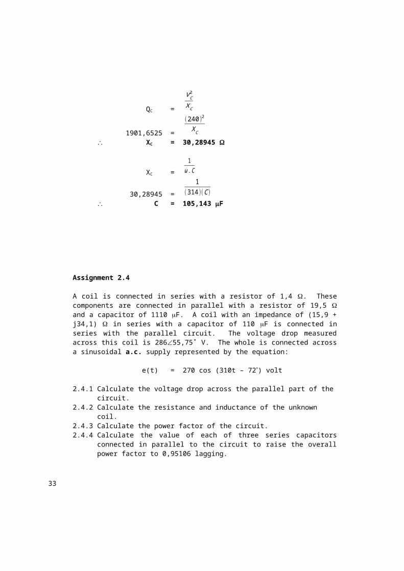
Assignment 2.4
A coil is connected in series with a resistor of 1,4 . These components are connected in parallel with a resistor of 19,5 and a capacitor of 1110 F. A coil with an impedance of (15,9 + j34,1) in series with a capacitor of 110 F is connected in series with the parallel circuit. The voltage drop measured across this coil is 28655,75˚ V. The whole is connected across a sinusoidal a.c. supply represented by the equation:
e(t) = 270 cos (310t – 72) volt
2.4.1 Calculate the voltage drop across the parallel part of the circuit.2.4.2 Calculate the resistance and inductance of the unknown coil.2.4.3 Calculate the power factor of the circuit.2.4.4 Calculate the value of each of three series capacitors connected in
parallel to the circuit to raise the overall power factor to 0,95106 lagging.
Solution:
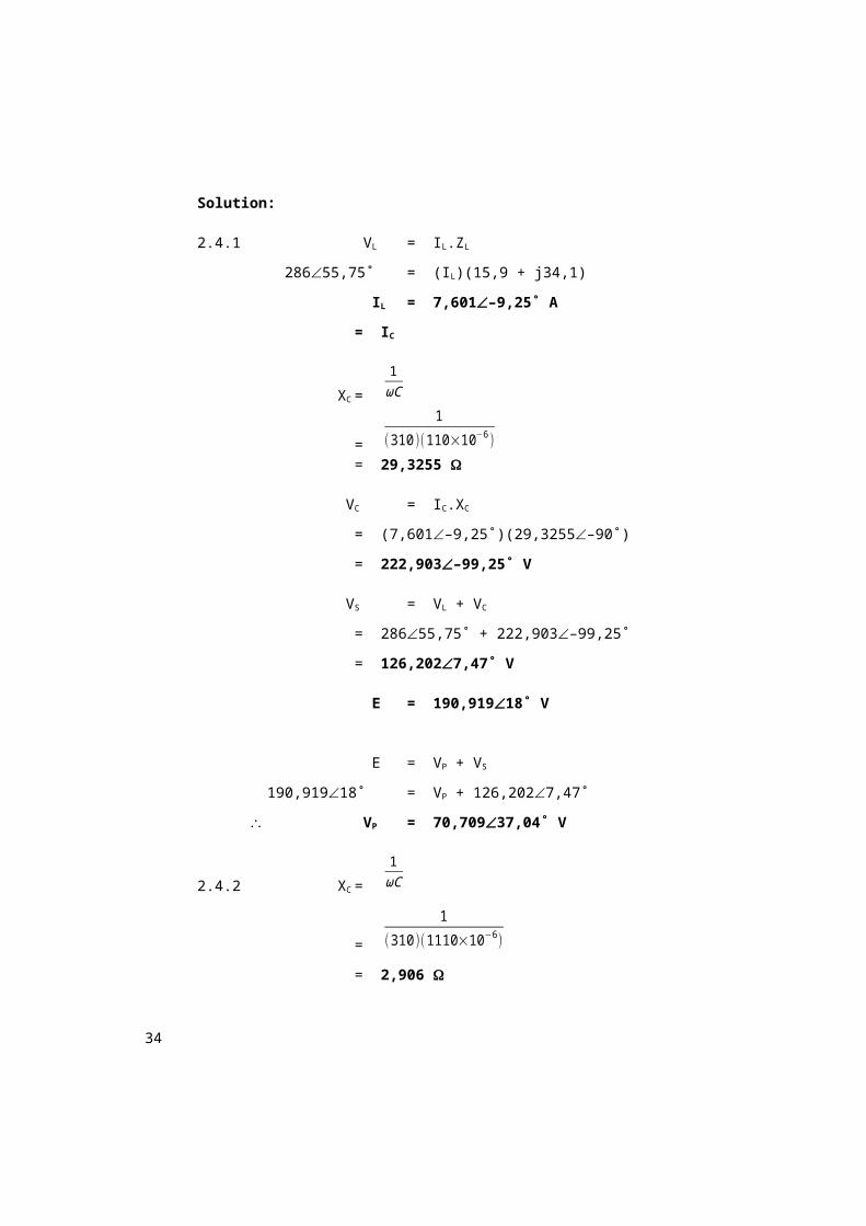
28
2.4.1 VL = IL.ZL
28655,75˚ = (IL)(15,9 + j34,1)
IL= 7,601–9,25˚ A
= IC
XC =
1ωC
=
1
(310 )(110×10−6 )= 29,3255
VC = IC.XC
= (7,601–9,25˚)(29,3255–90˚)
= 222,903–99,25˚ V
VS = VL + VC
= 28655,75˚ + 222,903–99,25˚
= 126,2027,47˚ V
E= 190,91918˚ V
E = VP + VS
190,91918˚ = VP + 126,2027,47˚
VP = 70,70937,04˚ V
2.4.2 XC =
1ωC
=
1
(310 )(1110×10−6 )
= 2,906
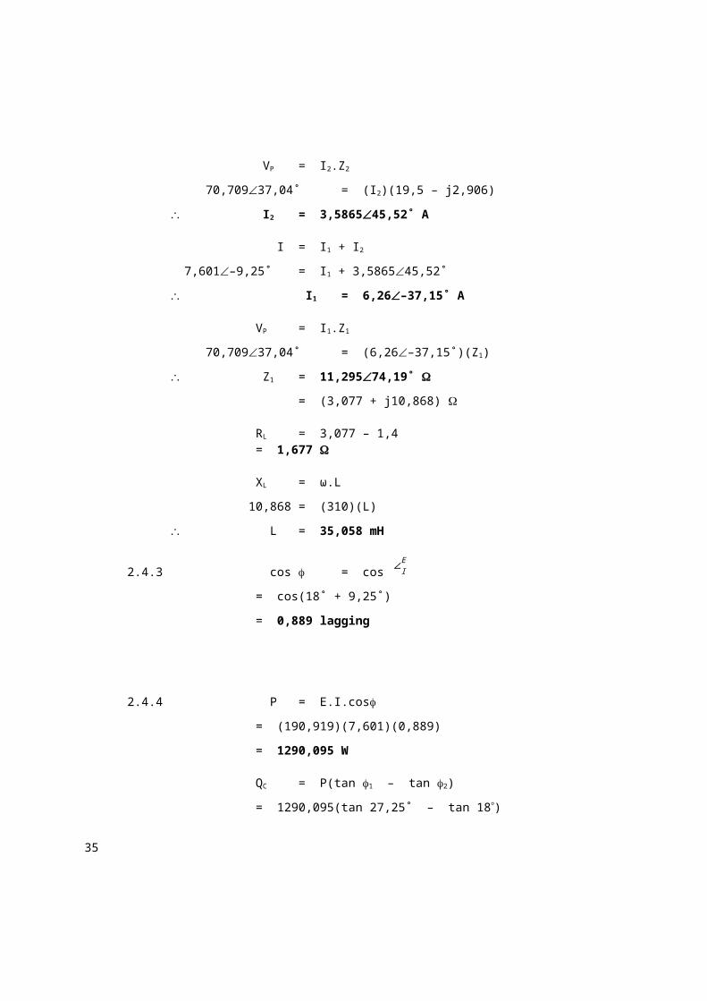
VP = I2.Z2
70,70937,04˚ = (I2)(19,5 – j2,906)
I2 = 3,586545,52˚ A
I = I1 + I2
29
7,601–9,25˚ = I1 + 3,586545,52˚
I1 = 6,26–37,15˚ A
VP = I1.Z1
70,70937,04˚ = (6,26–37,15˚)(Z1)
Z1 = 11,29574,19˚
= (3,077 + j10,868)
RL = 3,077 – 1,4= 1,677
XL = ω.L
10,868 = (310)(L)
L = 35,058 mH
2.4.3 cos = cos ∠IE
= cos(18˚ + 9,25˚)
= 0,889 lagging
2.4.4 P = E.I.cos
= (190,919)(7,601)(0,889)
= 1290,095 W
QC = P(tan 1 – tan 2)
= 1290,095(tan 27,25˚ – tan 18)
= 245,265 VAr
QC =
V C2
XC
245,265 =
(190 ,919)2
XC
XC = 148,615
30
XC =
1ω .C
148,615 =
1(310 )(C )
C = 21,706 F
1C =
1C1
+ 1C2
+ 1C3
121 ,706 =
3C1
C1 = 65,118 F
= C2
= C3
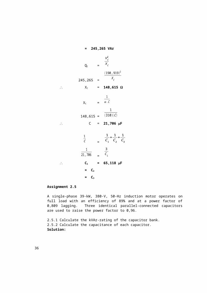
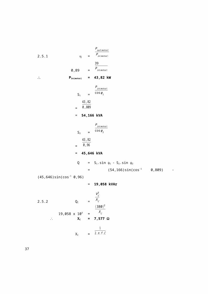
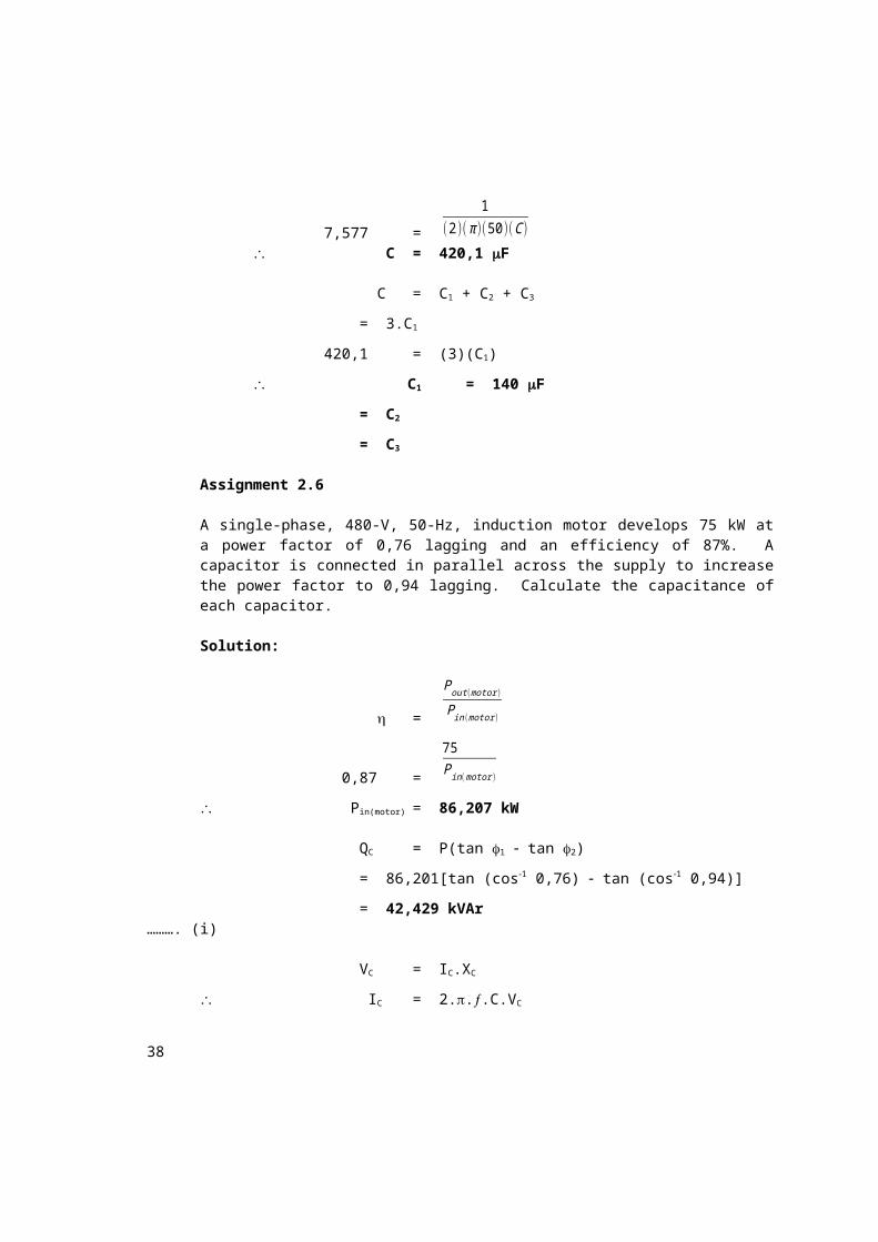
Assignment 2.5
A single-phase 39-kW, 380-V, 50-Hz induction motor operates on full load with an efficiency of 89% and at a power factor of 0,809 lagging. Three identical parallel-connected capacitors are used to raise the power factor to 0,96.
2.5.1 Calculate the kVAr-rating of the capacitor bank. 2.5.2 Calculate the capacitance of each capacitor.Solution:
A single-phase, 480-V, 50-Hz, induction motor develops 75 kW at a power factor of 0,76 lagging and an efficiency of 87%. A capacitor is connected in parallel across the supply to increase the power factor to 0,94 lagging. Calculate the capacitance of each capacitor.
Solution:
32
=
Pout (motor )
Pin(motor )
0,87=
75P in(motor )
Pin(motor) = 86,207 kW
QC = P(tan 1 tan 2)
= 86,201[tan (cos1 0,76) tan (cos1 0,94)]
= 42,429 kVAr ………. (i)
VC = IC.XC
IC = 2...C.VC
= (2)()(50)(C)(480)
= 150,79645(C) kA ………. (ii)
QC = VC.IC ………. (iii)
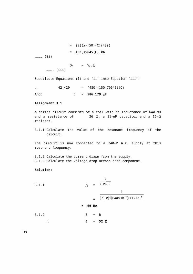
Substitute Equations (i) and (ii) into Equation (iii):
42,429= (480)(150,79645)(C)
And: C = 586,179 F
Assignment 3.1
A series circuit consists of a coil with an inductance of 640 mH and a resistance of 36 , a 11-F capacitor and a 16- resistor.
3.1.1 Calculate the value of the resonant frequency of the circuit.
The circuit is now connected to a 240-V a.c. supply at this resonant frequency:
3.1.2 Calculate the current drawn from the supply.3.1.3 Calculate the voltage drop across each component.
Solution:
33
3.1.1 r =
12. π √L .C
=
1
(2)( π )√(640×10−3 )(11×10−6 )
= 60 Hz
3.1.2 Z = R
Z = 52
E = I.Z
240= (I)(52)
I = 4,615 A
3.1.3 VR = I.R
= (4,615)(16)
= 73,84 V
XC =
12. π . f .C
=
1
(2)( π )(60)(11×10−6 )
= 241,144
= XL
VC = I.XC
= (4,615)(241,144–90˚)
= 1112,88–90˚ V
VL = I.ZL
= (4,615)(36 + j241,144)
= 1125,21381,51˚ V
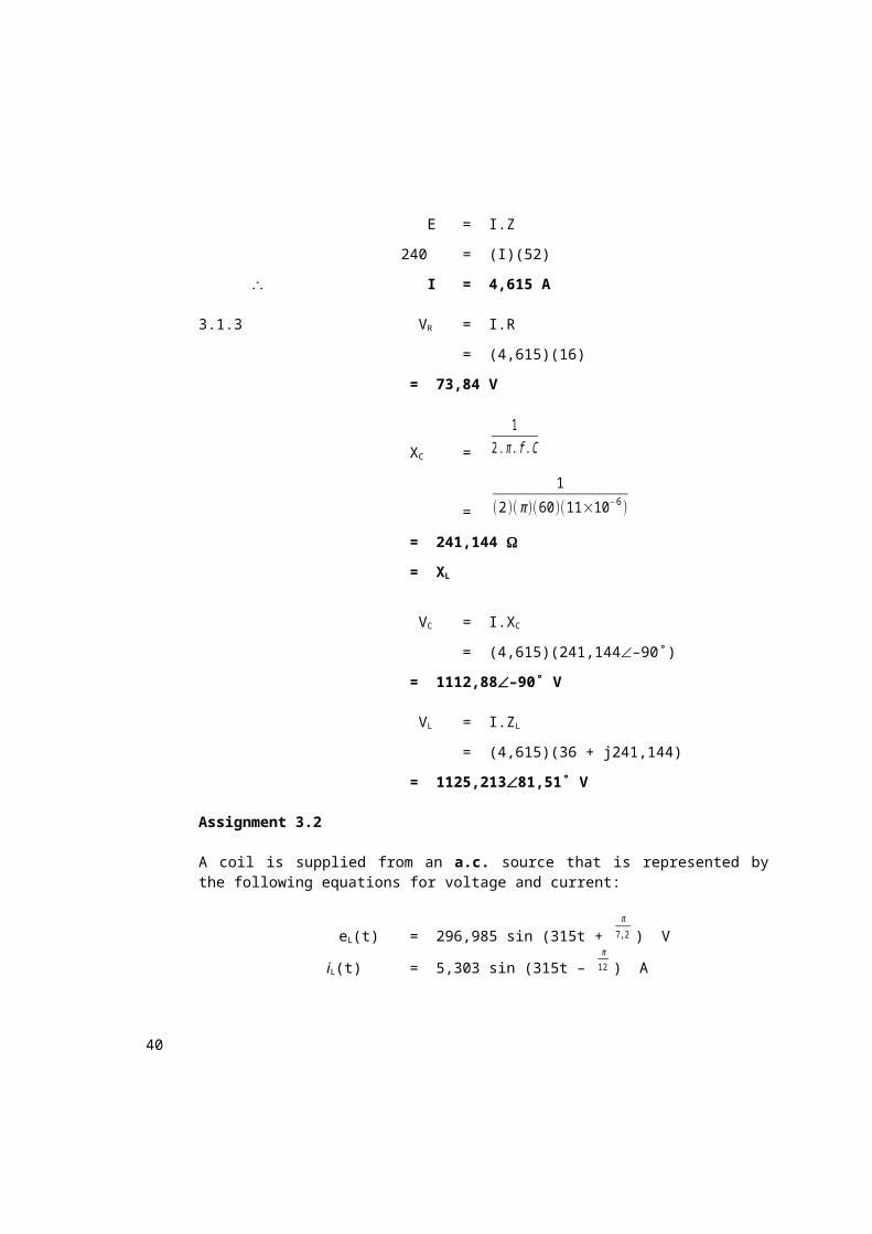
Assignment 3.2
A coil is supplied from an a.c. source that is represented by the following equations for voltage and current:
34
eL(t) = 296,985 sin (315t + π
7,2 ) V
iL(t) = 5,303 sin (315t – π12 ) A
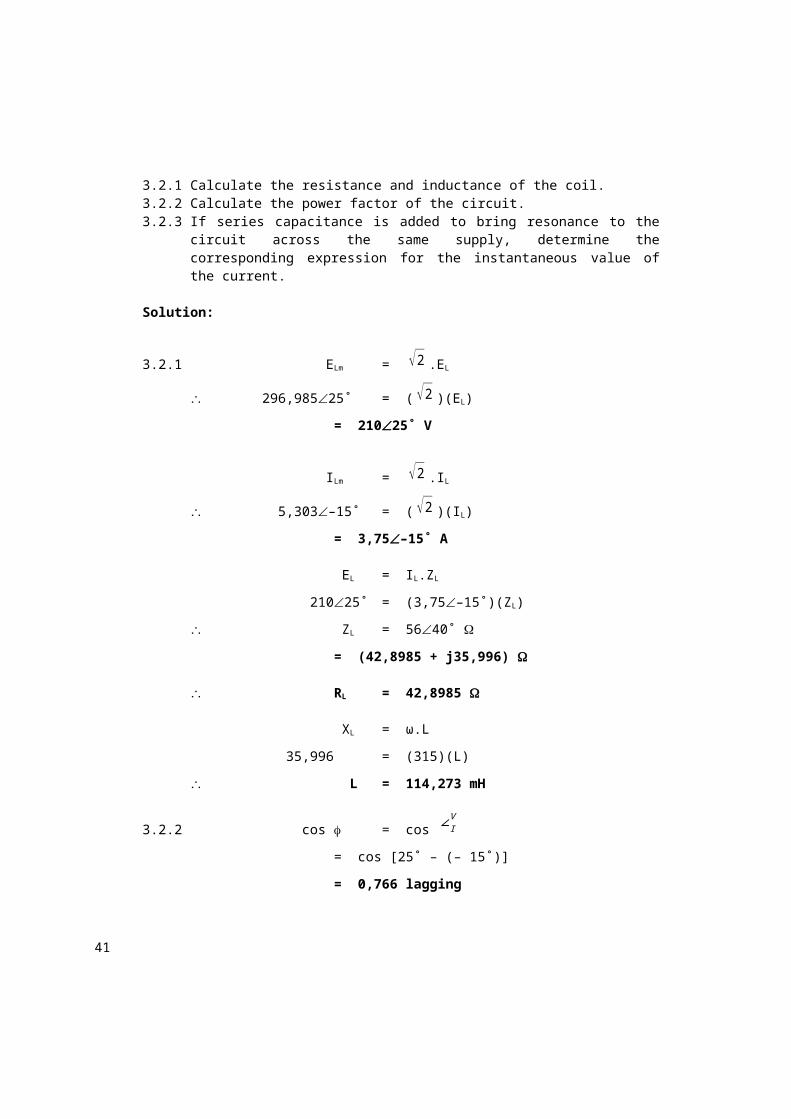
3.2.1 Calculate the resistance and inductance of the coil.3.2.2 Calculate the power factor of the circuit.3.2.3 If series capacitance is added to bring resonance to the circuit across
the same supply, determine the corresponding expression for the instantaneous value of the current.
Solution:
3.2.1 ELm = √2 .EL
296,98525˚ = (√2 )(EL)
= 21025˚ V
ILm = √2 .IL
5,303–15˚ = (√2 )(IL)
= 3,75–15˚ A
EL = IL.ZL
21025˚ = (3,75–15˚)(ZL)
ZL = 5640˚
= (42,8985 + j35,996)
RL = 42,8985
XL = ω.L
35,996= (315)(L)
L = 114,273 mH
3.2.2 cos = cos ∠IV
= cos [25˚ – (– 15˚)]
= 0,766 lagging
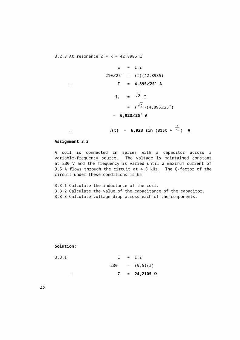
3.2.3 At resonance Z = R = 42,8985
35
E = I.Z
21025˚ = (I)(42,8985)
I = 4,89525˚ A
Im = √2 .I
= (√2 )(4,89525˚)
= 6,92325˚ A
i(t) = 6,923 sin (315t + π7,2 ) A
Assignment 3.3
A coil is connected in series with a capacitor across a variable-frequency source. The voltage is maintained constant at 230 V and the frequency is varied until a maximum current of 9,5 A flows through the circuit at 4,5 kHz. The Q-factor of the circuit under these conditions is 65.
3.3.1 Calculate the inductance of the coil.3.3.2 Calculate the value of the capacitance of the capacitor.3.3.3 Calculate voltage drop across each of the components.
Solution:
3.3.1 E = I.Z
230= (9,5)(Z)
Z = 24,2105
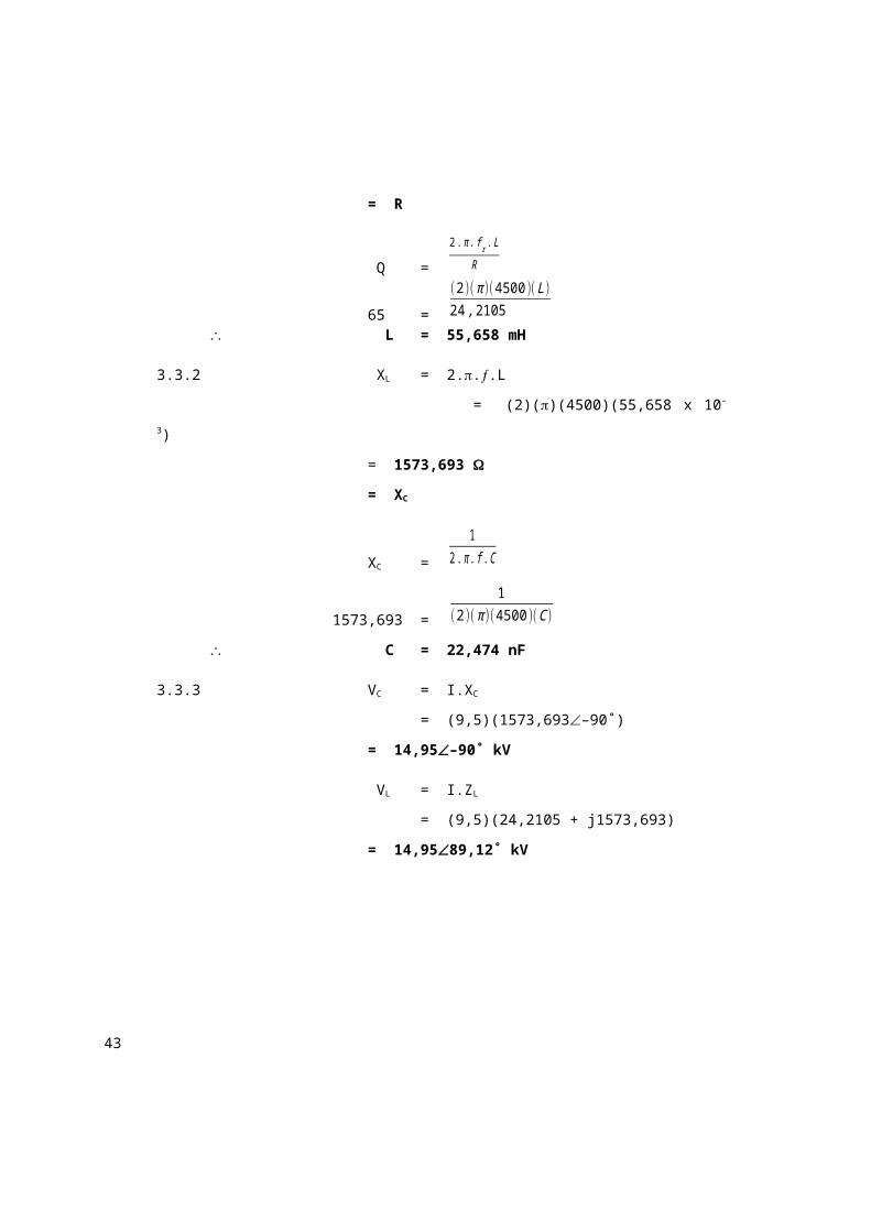
= R
Q =
2. π . f r . L
R
65 =
(2)( π )(4500 )(L)24 ,2105
L = 55,658 mH
36
3.3.2 XL = 2...L
= (2)()(4500)(55,658 x 10–3)
= 1573,693
= XC
XC =
12. π . f .C
1573,693 =
1(2)( π )(4500 )(C )
C= 22,474 nF
3.3.3 VC = I.XC
= (9,5)(1573,693–90˚)
= 14,95–90˚ kV
VL = I.ZL
= (9,5)(24,2105 + j1573,693)
= 14,9589,12˚ kV
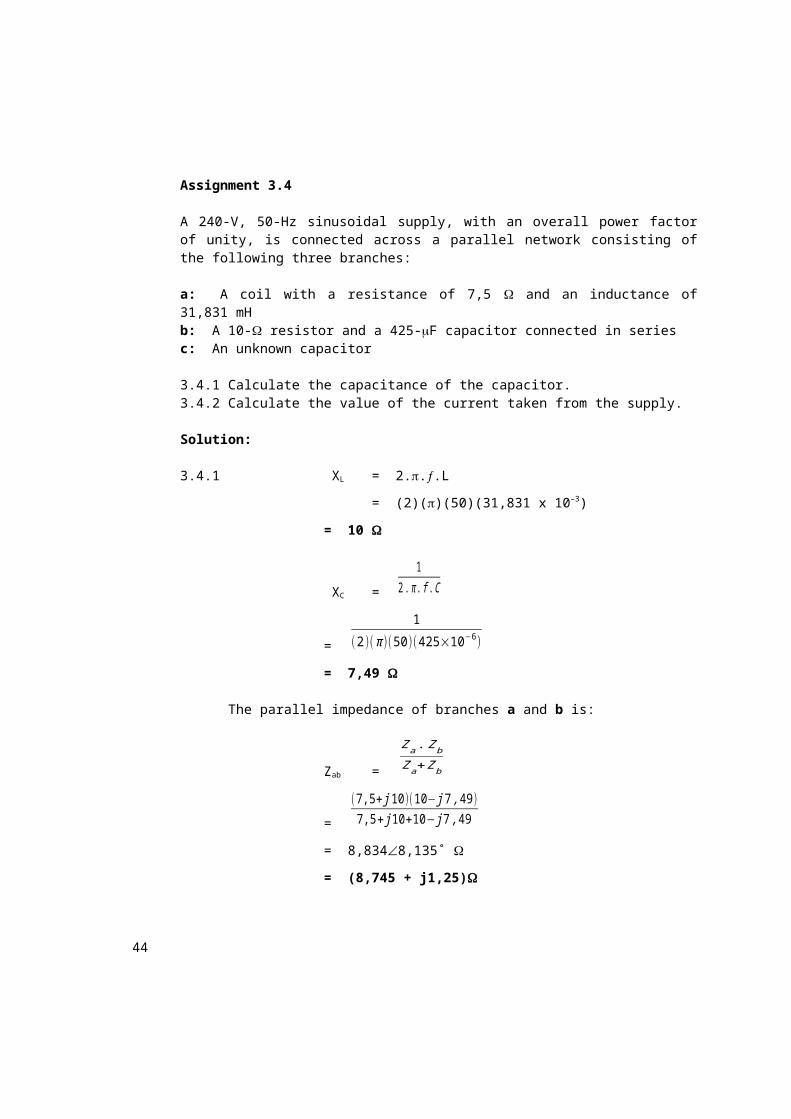
Assignment 3.4
A 240-V, 50-Hz sinusoidal supply, with an overall power factor of unity, is connected across a parallel network consisting of the following three branches:
a: A coil with a resistance of 7,5 and an inductance of 31,831 mHb: A 10- resistor and a 425-F capacitor connected in seriesc: An unknown capacitor
3.4.1 Calculate the capacitance of the capacitor.3.4.2 Calculate the value of the current taken from the supply.
Solution:
37
3.4.1 XL = 2...L
= (2)()(50)(31,831 x 10–3)
= 10
XC =
12. π . f .C
=
1
(2)( π )(50)( 425×10−6 )
= 7,49
The parallel impedance of branches a and b is:
Zab =
Za .Zb
Za+Zb
=
(7,5+ j10 )(10− j7 ,49 )7,5+ j 10+10− j7 ,49
= 8,8348,135˚
= (8,745 + j1,25)
XL = 2...L
1,25= (2)()(50)(L)
L = 3,979 mH
A power factor of unity means that the circuit is in resonance. Thus:
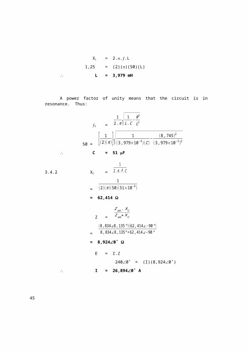
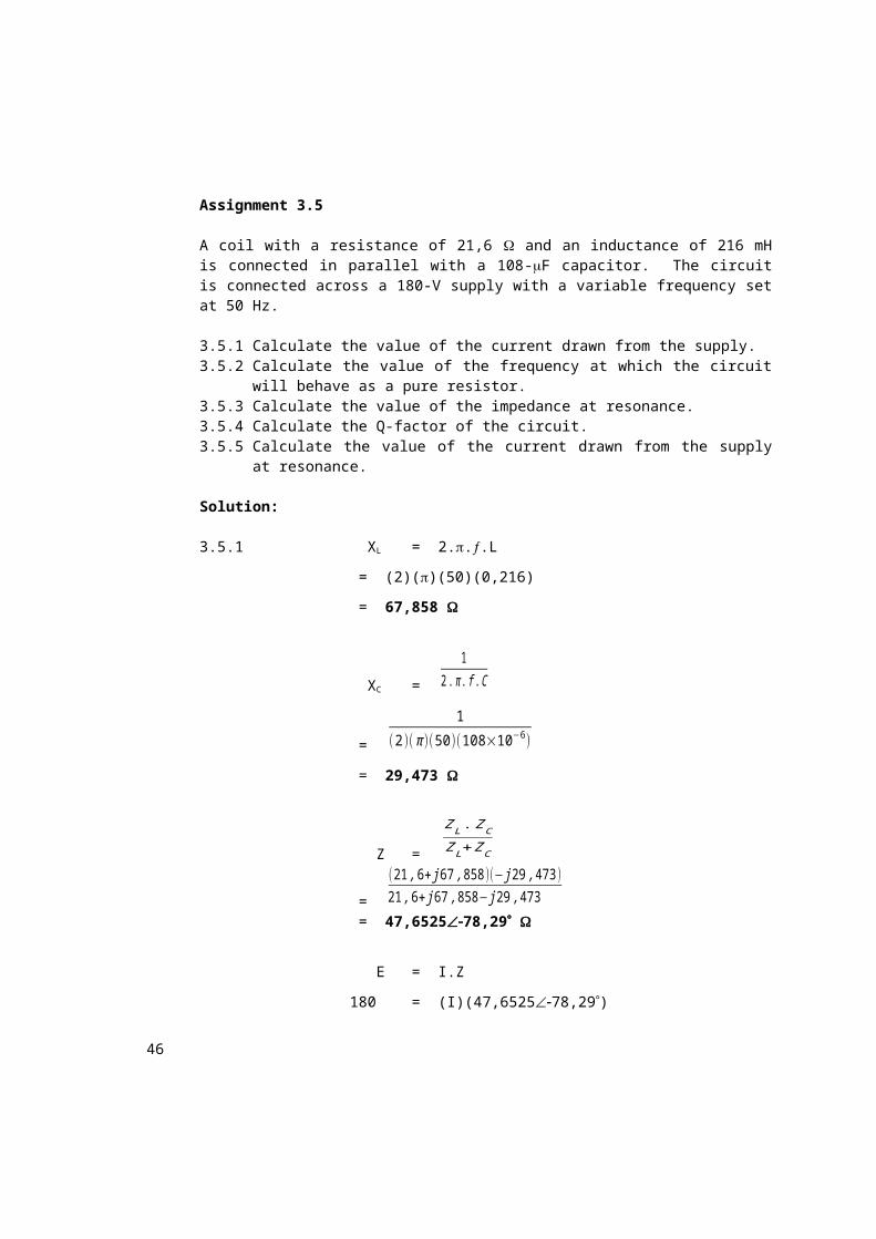
A coil with a resistance of 21,6 and an inductance of 216 mH is connected in parallel with a 108-F capacitor. The circuit is connected across a 180-V supply with a variable frequency set at 50 Hz.
3.5.1 Calculate the value of the current drawn from the supply.3.5.2 Calculate the value of the frequency at which the circuit will behave
as a pure resistor.3.5.3 Calculate the value of the impedance at resonance.3.5.4 Calculate the Q-factor of the circuit.3.5.5 Calculate the value of the current drawn from the supply at
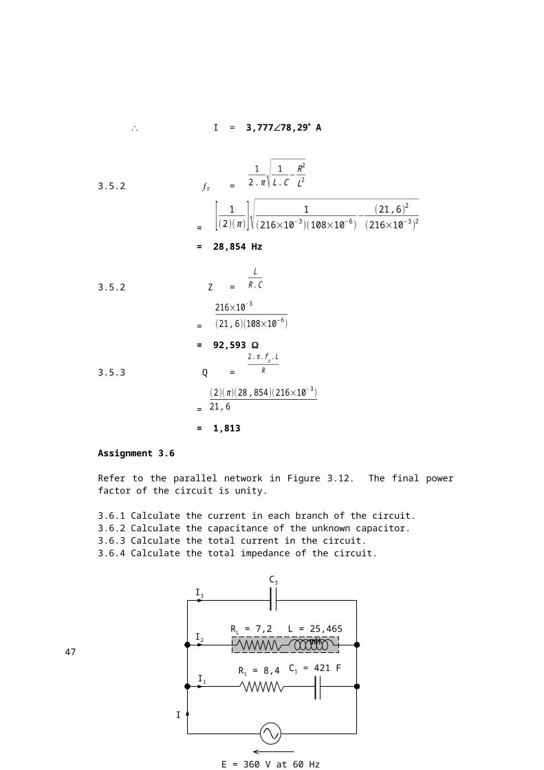
Refer to the parallel network in Figure 3.12. The final power factor of the circuit is unity.
3.6.1 Calculate the current in each branch of the circuit.
40
3.6.2 Calculate the capacitance of the unknown capacitor.3.6.3 Calculate the total current in the circuit.3.6.4 Calculate the total impedance of the circuit.
Figure 3.12: Parallel network for Assignment 3.6
Solution:
3.6.1 XC =
12. π . f .C
=
1
(2)( π )(60)( 421×10−6 )
= 6,301
E = I1.Z1
3600˚ = (I1)(8,4 – j6,301)
I1 = 34,28436,87˚ A
RL = 7,2
C1 = 421 FR1 = 8,4
L = 25,465 mH
C3
I
I3
I2
I1
E = 360 V at 60 Hz
41
XL = 2...L
= (2)()(60)(25,465 x 10–3)
= 9,6
E = I2.Z2
3600˚ = (I2)(7,2 + j9,6)
I2 = 30–53,13˚ A
Ip = I1 + I2
= 34,28436,87˚ + 30–53,13˚
= 45,555–4,315˚ A
= (45,426 – j 3,4275) A
I3 = 3,427590˚ A
3.6.2 E = I3.XC
3600˚ = (3,427590˚)(XC)
XC = 105,033
XC =
12. π . f .C
105,033 =
1(2)( π )(60)(C3 )
C3 = 25,255 F3.6.3 I = Ip + I3
= 45,555–4,315˚ + 3,427590˚
= 45,4260˚ A
3.6.4 E = I.Z
3600˚ = (45,4260˚)(Z)
Z = 7,9250˚
Assignment 3.7
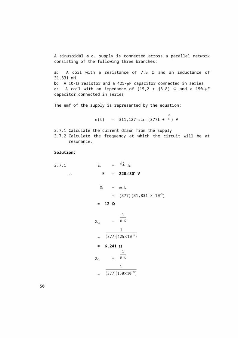
A sinusoidal a.c. supply is connected across a parallel network consisting of the following three branches:
a: A coil with a resistance of 7,5 and an inductance of 31,831 mHb: A 10- resistor and a 425-F capacitor connected in series
42
c: A coil with an impedance of (15,2 + j8,8) and a 150-F capacitor connected in series
The emf of the supply is represented by the equation:
e(t) = 311,127 sin (377t + π6 ) V
3.7.1 Calculate the current drawn from the supply.3.7.2 Calculate the frequency at which the circuit will be at resonance.
Solution:
3.7.1 Em = √2 .E
E = 22030 V
XL = .L
= (377)(31,831 x 10–3)
= 12
XCb =
1ω .C
=
1
(377 )(425×10−6 )
= 6,241
XCc =
1ω .C
=
1
(377 )(150×10−6 )
= 17,6835
1Z =
1Za +
1Zb +
1Zc
=
17,5+ j 12 +
110− j 6 ,241 +
115 ,2+ j 8,8− j17 ,6835
Z = 6,2874,92
E = I.Z
43
22030= (I)(6,2874,92)
I = 33,39934,92 A
3.7.2 C = 425 + 150
= 575 F
XLc = .Lc
8,8 = (377)(Lc)
Lc = 23,342 mH
L =
La .LcLa+Lc
=
(31 ,831)(23 ,342)31 ,831+23 ,342
= 13,467 mH
r =
12. π √ 1
L .C−R2
L2
=
1(2)( π ) √ 1
(0 ,013467 )(575×10−6 )−
(3 ,343 )2
(0 ,013467 )2
= 41,355 Hz
Assignment 4.1
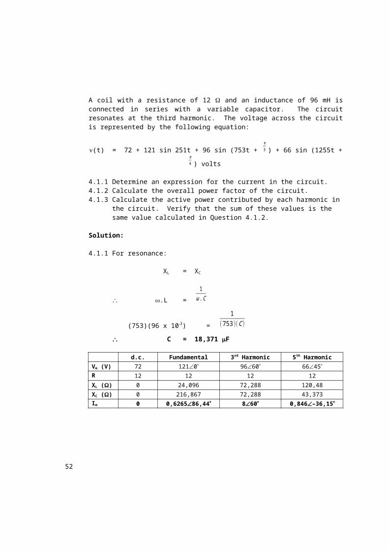
A coil with a resistance of 12 and an inductance of 96 mH is connected in series with a variable capacitor. The circuit resonates at the third harmonic. The voltage across the circuit is represented by the following equation:
(t) = 72 + 121 sin 251t + 96 sin (753t + π3 ) + 66 sin (1255t +
π4 ) volts
4.1.1 Determine an expression for the current in the circuit.4.1.2 Calculate the overall power factor of the circuit.4.1.3 Calculate the active power contributed by each harmonic in the
circuit. Verify that the sum of these values is the same value calculated in Question 4.1.2.
Solution:
4.1.1 For resonance:
44
XL = XC
.L =
1ω .C
(753)(96 x 103) =
1(753 )(C )
C= 18,371 F
d.c. Fundamental 3rd Harmonic 5th Harmonic
Vm (V) 72 1210 9660 6645
R () 12 12 12 12
XL () 0 24,096 72,288 120,48
XC () 0 216,867 72,288 43,373
Im (A) 0 0,626586,44 860 0,846–36,15
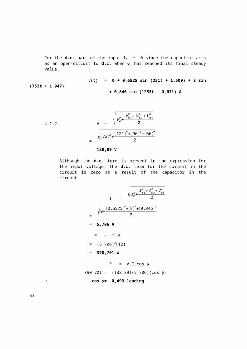
For the d.c. part of the input Im = 0 since the capacitor acts as an open-circuit to d.c. when C has reached its final steady value.
i(t) = 0 + 0,6525 sin (251t + 1,509) + 8 sin (753t + 1,047)
+ 0,846 sin (1255t – 0,631) A
4.1.2 V= √V 02+
Vm12 +Vm3
2 +V m52
2
= √(72 )2+(121)2+(96 )2+(66)2
2
= 138,89 V
Although the d.c. term is present in the expression for the input voltage, the d.c. term for the current in the circuit is zero as a result of the capacitor in the circuit.
I = √ I 02+
I m12 + Im3
2 + Im52
2
45
= √0+(0,6525 )2+(8)2+(0,846 )2
2
= 5,706 A
P = I2.R
= (5,706)2(12)
= 390,701 W
P = V.I.cos
390,701 = (138,89)(5,706)(cos )
cos = 0,493 leading
4.1.3 P0 = V0.I0
= 0 W
P1 = ½Vm1.Im1.cos 1
= (½)(121)(0,6525)cos (0˚ – 86,44)
= 2,451 W
P3 = ½Vm3.Im3.cos 3
= (½)(96)(8)(1)
= 384 W
P5 = ½Vm5.Im5.cos 5
= (½)(66)(0,846)cos(45˚ + 36,15˚)
= 4,295 W
P = P0 + P1 + P3 + P5
= 0 + 2,451 + 384 + 4,295
= 390,746 W
Assignment 4.2
A series RLC-circuit consists of a resistor of 18 , an inductor of 188 mH and a variable capacitor. The circuit resonates at the third harmonic. The voltage across the circuit is represented by the following equation:
46
(t) = 60 + 210 sin(314t +π9 ) + 159,3 sin(942t +
π4 ) + 105 sin(1570t +
π6 )
volts
4.2.1 Determine an expression for the current in the circuit.4.2.2 Calculate the overall power factor of the circuit.
Solution:
4.2.1 For resonance:
XL = XC
.L=
1ω .C
(942)(188 x 103) =
1(942 )(C )
C = 5,994 F
d.c. Fundamental 3rd Harmonic 5th Harmonic
Vm (V) 60 21020 159,345 10530
R () 18 18 18 18
XL () 0 59,032 177,036 295,16
XC () 0 531,317 177,036 106,263
Z () 180 472,62887,82 180 189,75384,56
Im (A) 0 0,444107,82 8,8545 0,55354,56i(t) = 0 + 0,444 sin (314t + 1,533) + 8,833 sin (942t+ 0,785) + 0,553 sin (1570t
0,952) A
4.2.2 V = √V 02+
Vm12 +Vm3
2 +V m52
2
= √(60 )2+(210 )2+(159,3 )2+(105)2
2
= 209,406 V
I =√ I 02+
I m12 + Im3
2 + Im52
2
47
= √0+(0,444 )2+(8,85 )2+( 0,553)2
2
= 6,278 A
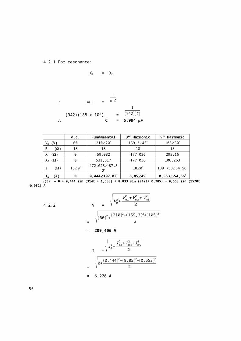
P = I2.R
= (6,278)2(18)
= 709,439 W
P = V.I.cos
709,439 = (209,406)(6,278)(cos )
cos = 0,5396 leading
Assignment 4.3
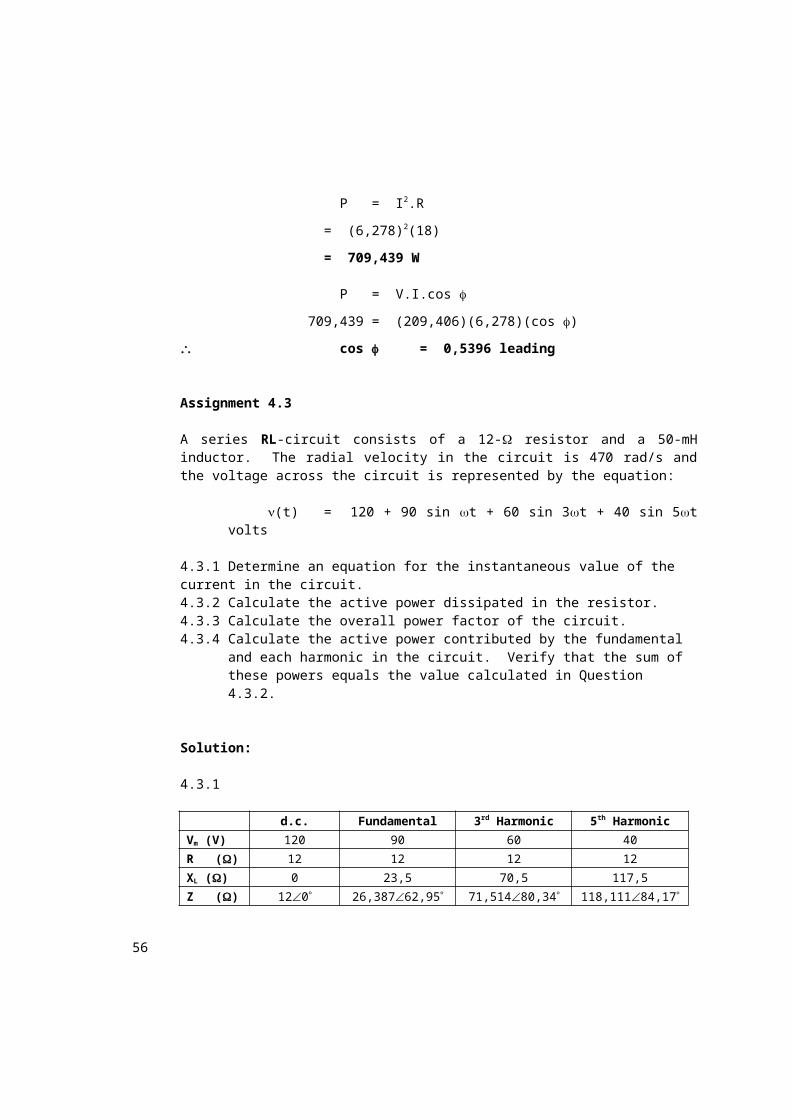
A series RL-circuit consists of a 12- resistor and a 50-mH inductor. The radial velocity in the circuit is 470 rad/s and the voltage across the circuit is represented by the equation:
(t) = 120 + 90 sin t + 60 sin 3t + 40 sin 5t volts
4.3.1 Determine an equation for the instantaneous value of the current in the circuit.4.3.2 Calculate the active power dissipated in the resistor.4.3.3 Calculate the overall power factor of the circuit.4.3.4 Calculate the active power contributed by the fundamental and each
harmonic in the circuit. Verify that the sum of these powers equals the value calculated in Question 4.3.2.
Solution:
4.3.1
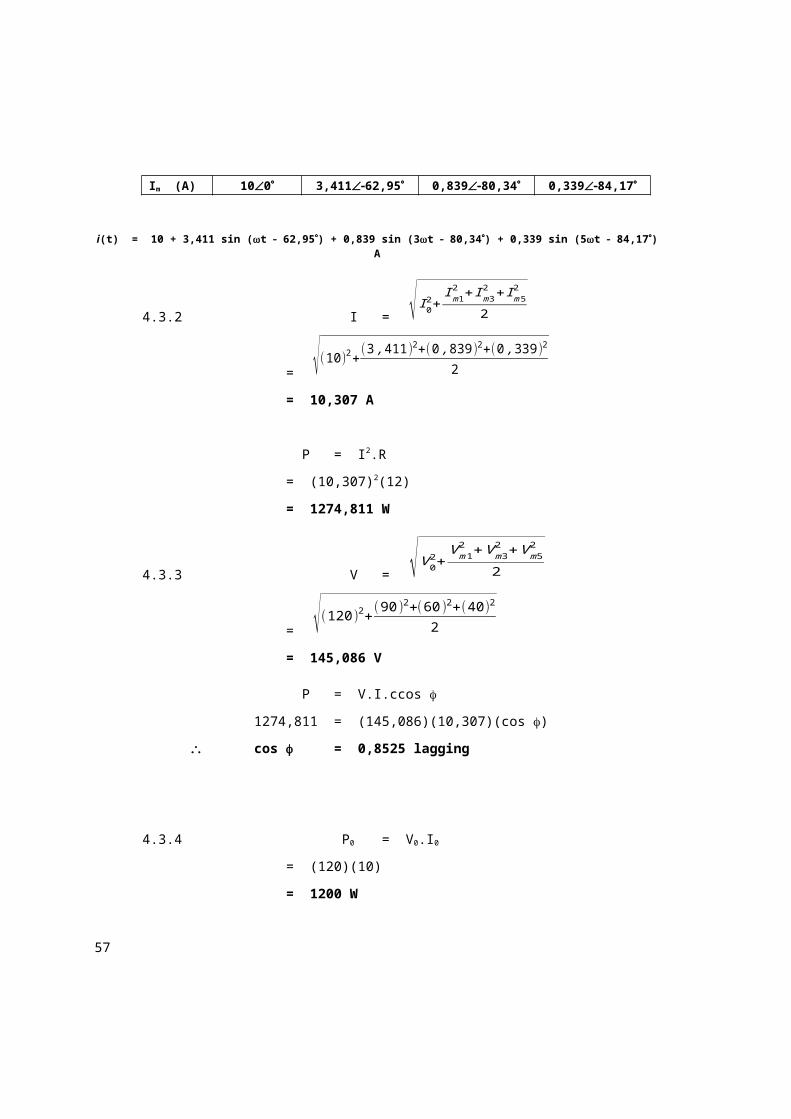
d.c. Fundamental 3rd Harmonic 5th Harmonic
Vm (V) 120 90 60 40
R () 12 12 12 12
XL () 0 23,5 70,5 117,5
Z () 120 26,38762,95 71,51480,34 118,11184,17
Im (A) 100 3,41162,95 0,83980,34 0,33984,17
i(t) = 10 + 3,411 sin (t 62,95) + 0,839 sin (3t 80,34) + 0,339 sin (5t 84,17) A
48
4.3.2 I = √ I 02+
Im12 + Im3
2 + Im52
2
= √(10 )2+(3 ,411)2+(0 ,839)2+(0 ,339)2
2
= 10,307 A
P = I2.R
= (10,307)2(12)
= 1274,811 W
4.3.3 V = √V 02+
Vm12 +V m3
2 +Vm52
2
= √(120 )2+(90 )2+(60)2+(40 )2
2
= 145,086 V
P = V.I.ccos
1274,811 = (145,086)(10,307)(cos )
cos = 0,8525 lagging
4.3.4 P0 = V0.I0
= (120)(10)
= 1200 W
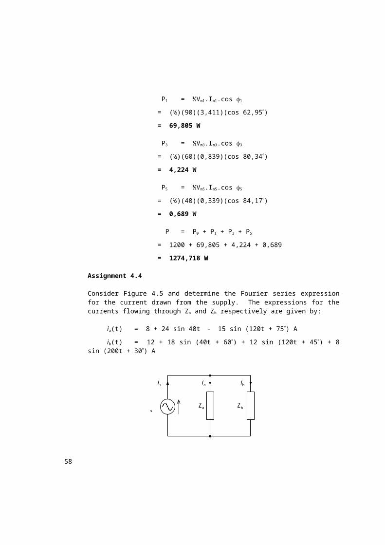
P1 = ½Vm1.Im1.cos 1
= (½)(90)(3,411)(cos 62,95)
= 69,805 W
P3 = ½Vm3.Im3.cos 3
= (½)(60)(0,839)(cos 80,34)
= 4,224 W
49
P5 = ½Vm5.Im5.cos 5
= (½)(40)(0,339)(cos 84,17)
= 0,689 W
P = P0 + P1 + P3 + P5
= 1200 + 69,805 + 4,224 + 0,689
= 1274,718 W
Assignment 4.4
Consider Figure 4.5 and determine the Fourier series expression for the current drawn from the supply. The expressions for the currents flowing through Za and Zb respectively are given by:
ia(t) = 8 + 24 sin 40t 15 sin (120t + 75) A
ib(t) = 12 + 18 sin (40t + 60) + 12 sin (120t + 45) + 8 sin (200t + 30) A
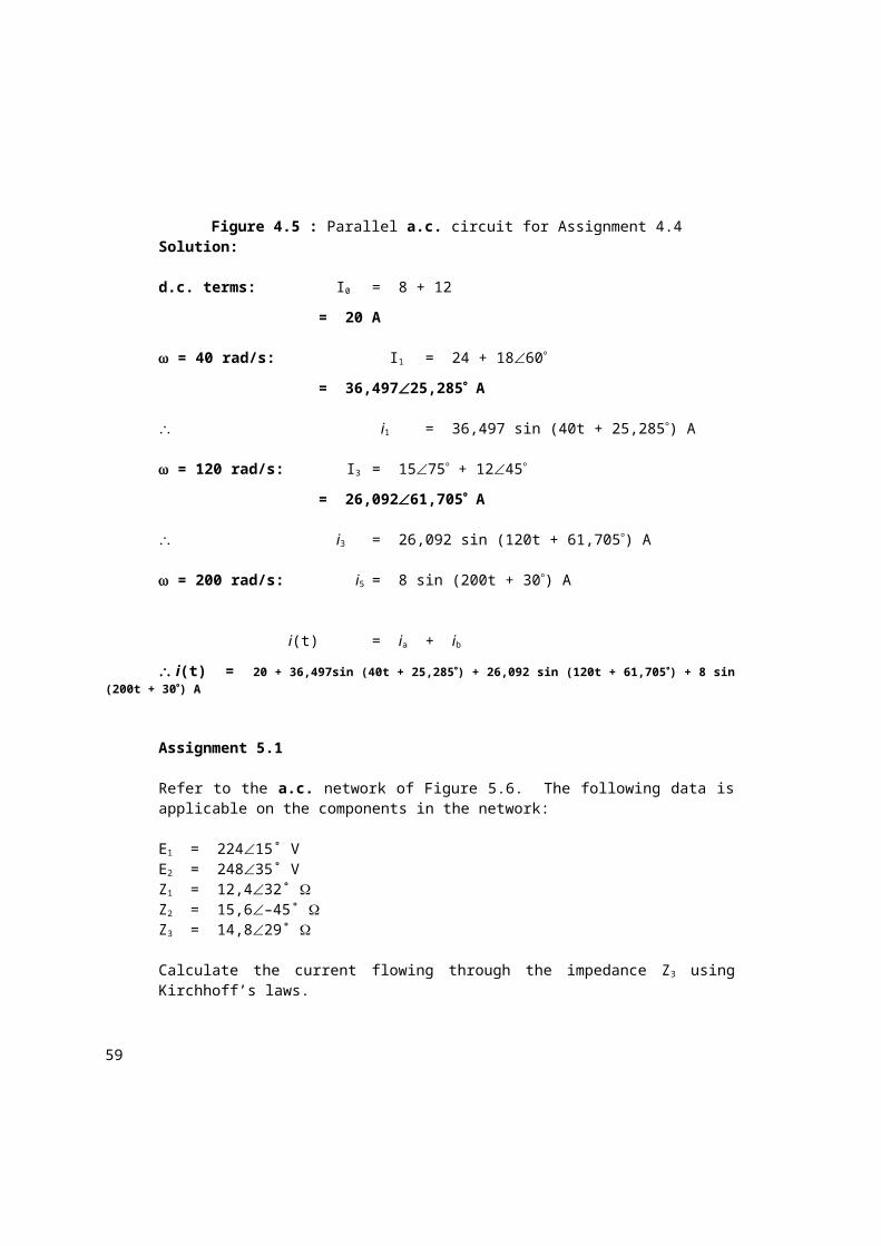
Figure 4.5 : Parallel a.c. circuit for Assignment 4.4Solution:
d.c. terms: I0 = 8 + 12
= 20 A
= 40 rad/s: I1 = 24 + 1860
= 36,49725,285 A
i1 = 36,497 sin (40t + 25,285) A
= 120 rad/s: I3= 1575 + 1245
= 26,09261,705 A
i3 = 26,092 sin (120t + 61,705) A
ZbZa
ibiais
s
50
= 200 rad/s: i5 = 8 sin (200t + 30) A
i(t) = ia + ib
i(t) = 20 + 36,497sin (40t + 25,285) + 26,092 sin (120t + 61,705) + 8 sin (200t + 30) A
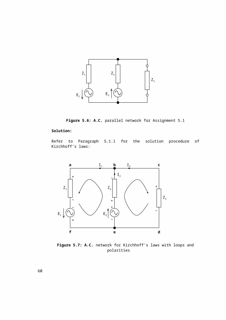
Assignment 5.1
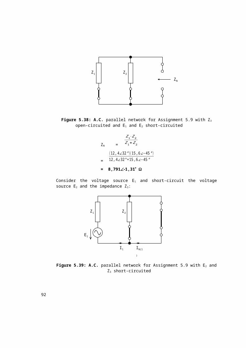
Refer to the a.c. network of Figure 5.6. The following data is applicable on the components in the network:
A balanced, three-phase, four-wire, star-connected load of (12,8 + j8,4) ohms per phase is connected to a symmetrical, three-phase, 380-V supply. Take Eab as reference and a positive phase sequence.
6.1.1 Calculate the values of the phase and line currents.6.1.2 Calculate the sum of the line voltages.6.1.3 Calculate the value of the neutral current flowing in the neutral wire
from the supply.
Solution:
No three-phase problem should be started without the phasor diagram!
Ebn Ean
EcnEca
Ebc
Eab
30˚
30˚
30˚
99
Figure 6.15: Positive (abc) phase sequence with Eab as reference
The value of the neutral current is zero. Remember that this is only true for the special case of a balanced system.
Assignment 6.2
In a balanced, three-phase, 380-V, 50-Hz, star-delta system the 28,35 kW load is supplied at a power factor 0,875 lagging. Take Vbc as reference with a positive phase sequence.
6.2.1 Calculate the power absorbed per phase.6.2.2 Calculate the value of the phase currents.6.2.3 Calculate the value of the line currents.6.2.4 Calculate the effective impedance of the load per phase.
Solution:
Figure 6.20: Line diagram of the star-delta system with the supply and load voltages and line and phase currents
Ica
Iab
Ibc
Three-phase loadThree-phase supply
Ic
Ib
Ia
VbcEbc
Eca VcaVabEab
c b
a
101
Figure 6.21: Positive (abc) phase sequence with Vbc as reference
6.2.1 Active power in each phase:
Ptot = 3Pph
28,35= (3)(Pph)
Pph = 9,45 kW
= Pab
= Pbc
= Pca
6.2.2 Current in each phase:
Pbc = Vbc.Ibc.cos ∠I bc
V bc
9,45 x 103 = (380)(Ibc)(0,875)
Ibc = 28,42128,96 A
Iab = 28,421( 28,96 + 120)
= 28,42191,04 A
Ica = 28,421(28, 96 120)
= 28,421148,96 A
6.2.3 Current in each line:
Ia = Iab Ica
= 28,42191,04° 28,421148,96°
= 49,22761,04° A Ib = Ibc Iab
= 28,42128,96° 28,42191,04°
Vab
Vca
Vbc
102
= 49,22758,96° A
Ic = Ica Ibc
= 28,421148,96° 28,42128,96°
= 49,227178,96° A
For a balanced load, once the phase currents are found, the line currents can be determined:
A 360-V, symmetrical, three-phase supply is connected to a balanced, delta-connected, three-phase load of phase impedance (8,45 + j6,36) . Take Vac
as reference phasor with a negative phase sequence.
6.3.1 Calculate the value of the phase currents.6.3.2 Calculate the power absorbed per phase.6.3.3 Calculate the total power absorbed by the load.6.3.4 Calculate the phasor sum of the three line currents.6.3.5 Convert the load to an equivalent star-connected load.
103
6.3.6 Calculate the total power absorbed by the star-connected load.
Solution:
Figure 6.22: Negative (cba) phase sequence with Vac as reference6.3.1 Current in each phase of the load:
Vab = Iab.Zab
36060 = (Iab)(8,45 + j6,36)
Iab = 34,03996,97° A
Vbc = Ibc.Zbc
36060= (Ibc)(8,45 + j6,36)
Ibc = 34,03923,03° A
Vca = Ica.Zca
360180= (Ica)(8,45 + j6,36)
Ica = 34,039143,03° A
6.3.2 Sab¿
= Vab.I ab¿
= (36060°)(34,03996,97°)
= 12254,0436,97°
= (9790,372 + j7369,54) VA
Pab = 9790,372 W
= Pbc
= Pca
Or: Pab = I ab2
.Rab
30˚
30˚
30˚VanVcn
Vbn
Vac
Vab
Vca
Vbc
104
= (34,039)2(8,45)
= 9790,622 W
6.3.3 P = 3.Pph
= (3)(9790,622)
= 29,372 kW
6.3.4 Current in each line:
Ia = Iab Ica
= 34,03996,97° 34,039143,03°
= 58,95766,97° A
Ib = Ibc Iab
= 34,03923,03° 34,03996,97°
= 58,95753,03° A
Ic = Ica Ibc
= 34,039143,03° 34,03923,03°
= 58,957173,03° A
Ia + Ib + Ic = 58,95766,97 + 58,95753,03 + 58,957173,03
= 0 A
As shown, the sum of the three line currents drawn by a balanced load is zero. This means that these currents are equal in magnitude and a phase difference of 120° exists between them.