ADDITIONAL RESOURCES We use electrical circuits every day. In the home, the car, at work and school – they are a vital part of our lives. This program covers the basics of electrical circuits in detail. It looks at various components of a circuit; voltage, current, resistance and Ohm’s Law; series and parallel circuits; and demonstrates a range of calculations for voltage, current, resistance, power and the use of Kirchhoff’s Law. It also covers how to use a multimeter; resistors and resistance colour coding. Learners are provided with clear verbal and visual explanations of the movement of current through a circuit, how it flows and how electrical energy is used, and easy-to- follow examples of how Ohm’s and Kirchhoff’s Laws are applied. The content is ideal for middle level science students, and essential viewing for entry level vocational learners in electrical and allied trades. Duration of resource: 23 Minutes Year of Production: 2013 Stock code: VEA12041 Resource written by: Derek Bailey B of Ed (VET), Cert IV TAE10, NSW Licensed Electrician, Qualified Supervisor and Contractor, Public RTO Teacher
Transcript
ADDITIONAL RESOURCES
We use electrical circuits every day. In the home, the car, at work and school – they are a vital part of our lives. This program covers the basics of electrical circuits in detail. It looks at various components of a circuit; voltage, current, resistance and Ohm’s Law; series and parallel circuits; and demonstrates a range of calculations for voltage, current, resistance, power and the use of Kirchhoff’s Law. It also covers how to use a multimeter; resistors and resistance colour coding. Learners are provided with clear verbal and visual explanations of the movement of current through a circuit, how it flows and how electrical energy is used, and easy-to-follow examples of how Ohm’s and Kirchhoff’s Laws are applied. The content is ideal for middle level science students, and essential viewing for entry level vocational learners in electrical and allied trades.
You may download and print one copy of these support notes from our website or ClickView for your reference. Further copying or printing must be reported to CAL as per the Copyright Act 1968.
For Teachers
Introduction The purpose of the ‘Electrical Circuits’ training video is to identify the key basic parts of an electric circuit and the different results observed, depending on the components, materials and configuration used for a particular circuit. The principles and ideas demonstrated correspond with the prerequisite knowledge for a range of Australian National Training Package Units of Competency. They are suitable for various electro technology qualification pathways and are applicable to senior secondary physics. By the use of guided demonstration, wiring diagrams and animated schematics (electric circuits drawn to applicable standards and codes), the viewer is shown: an explanation of what makes an electrical circuit; introduced to the applicable terminology for the basic elements and components used; and the observable and repeatable phenomena, such as voltage, current, resistance and power.
Timeline 00:00:00 Introduction to circuits 00:04:17 Series circuits 00:07:58 Parallel circuits 00:09:57 Calculations 00:14:12 Measurements 00:17:50 Resistors 00:21:57 Credits 00:22:31 End program
Related Titles One Flash and You're Ash! – Working Safely With Electricity
You may download and print one copy of these support notes from our website or ClickView for your reference. Further copying or printing must be reported to CAL as per the Copyright Act 1968.
Student Worksheet
Initiate Prior Learning 1. List the toys, equipment, computer, entertainment devices that use electricity from mains power
(including charging devices) that you use on a daily basis. ____________________________________________________________________________________ ____________________________________________________________________________________ ____________________________________________________________________________________ ____________________________________________________________________________________ ____________________________________________________________________________________ ____________________________________________________________________________________ 2. If there was no power available for you to use the items listed in question 1, what one item would
affect you the most and why? ____________________________________________________________________________________ ____________________________________________________________________________________ ____________________________________________________________________________________ 3. Apart from plugging the item of question 2 into the normal electrical distributed mains power system,
what alternative sources of electricity could be used to provide the required electrical power? ____________________________________________________________________________________ ____________________________________________________________________________________ ____________________________________________________________________________________ 4. From the alternative sources that you have described which one do you think would be the easiest to
construct and maintain? ____________________________________________________________________________________ 5. What do you do to stop wasting electricity in your everyday life? ____________________________________________________________________________________ ____________________________________________________________________________________ ____________________________________________________________________________________
You may download and print one copy of these support notes from our website or ClickView for your reference. Further copying or printing must be reported to CAL as per the Copyright Act 1968.
Active Viewing Guide Introduction to Circuits 1. Name the basic parts of an electrical circuit? ____________________________________________________________________________________ ____________________________________________________________________________________ ____________________________________________________________________________________ 2. Describe in your own words the difference between electromotive force (EMF) and potential difference
(PD) in an electrical circuit? ____________________________________________________________________________________ ____________________________________________________________________________________ ____________________________________________________________________________________ ____________________________________________________________________________________ 3. What are the accepted practices to show the flow of electrons and current in an energised complete
electrical circuit? Use a diagram to illustrate your response.
You may download and print one copy of these support notes from our website or ClickView for your reference. Further copying or printing must be reported to CAL as per the Copyright Act 1968.
4. In an electrical circuit that is complete, the opposition to electron flow is known as? ____________________________________________________________________________________ 5. Name the result of the combination of opposition to electron flow, and potential differences supplied by
the emf of the circuit to a complete electrical circuit. ____________________________________________________________________________________ 6. In a direct current circuit, state the relationship between voltage (potential difference), current and
resistance using their associated symbols and units as described by Ohm’s law. ____________________________________________________________________________________ ____________________________________________________________________________________ ____________________________________________________________________________________ ____________________________________________________________________________________ 7. Power used by an electrical circuit is the product of what two terms of Ohm’s law? ____________________________________________________________________________________ ____________________________________________________________________________________ 8. Can the power in a series direct current circuit be found if only the resistance and voltage are known?
Explain your answer. ____________________________________________________________________________________ ____________________________________________________________________________________ ____________________________________________________________________________________
You may download and print one copy of these support notes from our website or ClickView for your reference. Further copying or printing must be reported to CAL as per the Copyright Act 1968.
9. Using three separate diagrams to describe the terms open, closed and short electrical circuits. Series Circuits 10. Draw a circuit having one EMF source, a closed switch and four incandescent lamps in series.
a) Label all the items and number the lamps R1 to R4 in the sequence of current flow.
You may download and print one copy of these support notes from our website or ClickView for your reference. Further copying or printing must be reported to CAL as per the Copyright Act 1968.
b) If each lamp has a PD of 3 V (voltage)) and the circuit current, I, is measured (after the switch is
closed) at 2.4 A (amperes) direct current, what is the resistance stated in Ω (Ohms) for each lamp? ____________________________________________________________________________________ ____________________________________________________________________________________ ____________________________________________________________________________________
c) What is the total power in W (Watts) taken by the four lamps? ____________________________________________________________________________________ ____________________________________________________________________________________ ____________________________________________________________________________________ 11. Explain the specific use or purpose of a voltage divider in an electrical circuit. ____________________________________________________________________________________ ____________________________________________________________________________________ ____________________________________________________________________________________
a) What must you remember when choosing appropriate resistors for the voltage divider? ____________________________________________________________________________________ ____________________________________________________________________________________ ____________________________________________________________________________________ 12. Name three applications of the use of a series circuit in domestic premises using alternating current. ____________________________________________________________________________________ ____________________________________________________________________________________ ____________________________________________________________________________________
You may download and print one copy of these support notes from our website or ClickView for your reference. Further copying or printing must be reported to CAL as per the Copyright Act 1968.
Parallel Circuits 13. Draw a parallel circuit having one source of EMF, one control switch in open position and four resistors
in separate branches marked R1 to R4, R1 being the closest to the EMF after the switch and R4 being in the last branch.
a) If the source of EMF is 36 V (voltage), what is the individual PD (potential differences) or volt drop across each branch resistor?
b) The current in R1 is 0.2 A (ampere) or 200 µA (micro amperes) after the switch is closed and each branch resistor has the same rating in ohms, what is the total current flowing and what is the total power being consumed by the four resistors in parallel?
You may download and print one copy of these support notes from our website or ClickView for your reference. Further copying or printing must be reported to CAL as per the Copyright Act 1968.
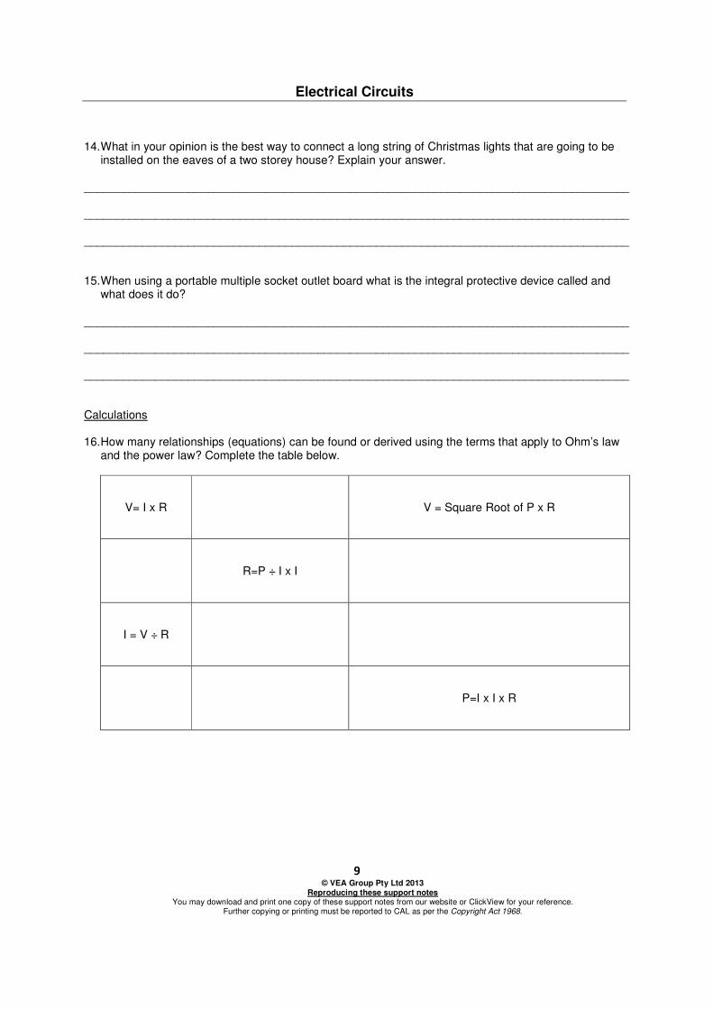
14. What in your opinion is the best way to connect a long string of Christmas lights that are going to be
installed on the eaves of a two storey house? Explain your answer. ____________________________________________________________________________________ ____________________________________________________________________________________ ____________________________________________________________________________________ 15. When using a portable multiple socket outlet board what is the integral protective device called and
what does it do? ____________________________________________________________________________________ ____________________________________________________________________________________ ____________________________________________________________________________________ Calculations 16. How many relationships (equations) can be found or derived using the terms that apply to Ohm’s law
You may download and print one copy of these support notes from our website or ClickView for your reference. Further copying or printing must be reported to CAL as per the Copyright Act 1968.
17. Kirchhoff’s law of current in a circuit states that the algebraic sum of the currents in a network of
conductor meeting at a point is zero. Use a labelled diagram to illustrate what this means in a practical circuit.
Measurements 18. A digital multimeter can be used to measure what characteristics found in direct current and
alternating current circuits? ____________________________________________________________________________________ ____________________________________________________________________________________ ____________________________________________________________________________________ ____________________________________________________________________________________ ____________________________________________________________________________________ 19. What precautions are necessary when measuring circuit characteristics? ____________________________________________________________________________________ ____________________________________________________________________________________ ____________________________________________________________________________________ ____________________________________________________________________________________ ____________________________________________________________________________________ ____________________________________________________________________________________
You may download and print one copy of these support notes from our website or ClickView for your reference. Further copying or printing must be reported to CAL as per the Copyright Act 1968.
Resistors 20. State what three pieces of information are found when examining the colour code bands of a fixed
value resistor. ____________________________________________________________________________________ ____________________________________________________________________________________ ____________________________________________________________________________________ 21. By use of diagrams show the major differences between a potentiometer and a rheostat.
a) State what other name is used for a potentiometer. ____________________________________________________________________________________
b) Name the practical uses for a potentiometer. ____________________________________________________________________________________ ____________________________________________________________________________________
You may download and print one copy of these support notes from our website or ClickView for your reference. Further copying or printing must be reported to CAL as per the Copyright Act 1968.
22. Describe the main characteristics and attributes of each of the following.
a) LDR ____________________________________________________________________________________ ____________________________________________________________________________________ ____________________________________________________________________________________
b) VDR ____________________________________________________________________________________ ____________________________________________________________________________________ ____________________________________________________________________________________
c) PTC ____________________________________________________________________________________ ____________________________________________________________________________________ ____________________________________________________________________________________
You may download and print one copy of these support notes from our website or ClickView for your reference. Further copying or printing must be reported to CAL as per the Copyright Act 1968.
Extension Activities 1. Undertake research to produce a report of approximately 500 words, about who first produced a
source of electromotive force and subsequently who improved on the original concepts. 2. Ohm’s Law states the relationship between V, I and R but what other factor (quantity/characteristic)
must be taken into account when designing electrical circuits? 3. What factor limits the ability of a resistor to produce an unchanging or steady state current when
supplied at a constant voltage, explain and illustrate your ideas and argument? 4. If resistance denotes the opposition to flow of electrons in an electrical circuit, what unit is used to
show how efficiently a material allows electrons to flow? Explain the definition of the unit chosen in your own words, and research how the unit is used to calculate Equivalent Resistance in parallel connected resistors.
5. Why is a potentiometer considered to be used principally to control or vary voltage and a rheostat
You may download and print one copy of these support notes from our website or ClickView for your reference. Further copying or printing must be reported to CAL as per the Copyright Act 1968.
Suggested Student Responses
Initiate Prior Learning 1. List the toys, equipment, computer, entertainment devices that use electricity from mains power
(including charging devices) that you regularly use on a daily basis. Answers will vary but could include: mobile phone, personal computer, note book, X Box, television, and appliances
2. If there was no power available for you to use the items listed in question 1, what one item would
affect you the most and why? Answers will vary
3. Apart from plugging the item of question 2 into the normal electrical distributed mains power system
what alternative sources of electricity could be used to provide the required electrical power? Answer will vary but could include; solar power, wind power, bio mass, micro hydro, combination using battery back-up to store excess
4. From the alternative sources that you have described which one do you think would be the easiest to
construct and maintain? Answers will vary
5. What do you do to stop wasting electricity in your everyday life?
Answer will vary but could include: switch off if not required; do not leave appliances on in stand-by mode.
You may download and print one copy of these support notes from our website or ClickView for your reference. Further copying or printing must be reported to CAL as per the Copyright Act 1968.
Active Viewing Guide Introduction to Circuits 1. Name the basic parts of an electrical circuit?
Source of EMF, load, conductor from EMF to load, conductor from load back to EMF and a control /protective device normally in conductor from EMF to Load.
2. Describe in your own words the difference between electromotive force (EMF) and potential difference
(PD) in an electrical circuit? Answer will vary but could include: EMF is that voltage which can be measured between the unloaded terminal of a supply source such as a cell or combination of cells to form a battery or alternate source. PD is the voltage drop that can be measured across the load and conductors of a circuit.
3. What are the accepted practices to show the flow of electrons and current in an energised complete
electrical circuit? Use a diagram to illustrate your response. Answers will vary but could include: Electrons flow from the negative terminal of a source of EMF to the positive terminal of the EMF source. Current is shown in the opposite direction; positive to negative terminals of an EMF source
4. In an electrical circuit that is complete the opposition to electron flow is known as?
Resistance 5. Name the result of the combination of opposition to electron flow and potential differences supplied by
the emf of the circuit to a complete electrical circuit. Current
6. In a direct current circuit, state the relationship between voltage (potential difference), current and
resistance using their associated symbols and units as described by Ohm’s law. Voltage (V) = Current (I) (A) (Ampere) x Resistance (Ohms) (Ω) Acceptable if the Ohm’s Law Triangle used
7. Power used by an electrical circuit is the product of what two terms of Ohm’s law?
Voltage (V) and Current (I) (A) (Ampere) 8. Can the power in a series direct current circuit be found if only the resistance and voltage are known?
Explain your answer. Yes by stating that Power (W) (Watts) = V x V ÷ R by substituting V ÷ R for I in P=V x I
9. Using three separate diagrams describe the terms open, closed and short electrical circuits.
Answers will vary but should include; One diagram switch in open position, another diagram with switch closed and one with no switch or load but terminals of EMF source bridged out
You may download and print one copy of these support notes from our website or ClickView for your reference. Further copying or printing must be reported to CAL as per the Copyright Act 1968.
Series Circuits 10. Draw a circuit having one EMF source, a closed switch and four incandescent lamps in series.
a) Label all the items and number the lamps R1 to R4 in the sequence of current flow. A Draw a circuit having one EMF source, a closed switch and four incandescent lamps in series. B Label all the items and number the lamps R1 to R4 in the sequence of current flow. C If each lamp has a PD of 3 V (Voltage)) and the circuit current I, after the switch is closed, is measured at 2.4 A (Amperes) direct current, what is the resistance stated in Ω (Ohms) for each lamp? D What is the total power in W (Watts) taken by the four lamps?
b) If each lamp has a PD of 3 V (voltage)) and the circuit current, I, is measured (after the switch is
closed) at 2.4 A (amperes) direct current, what is the resistance stated in Ω (Ohms) for each lamp? R for each lamp is 1.25 Ω
c) What is the total power in W (Watts) taken by the four lamps?
P Total = 12 V x 2.4 A = 28.8 W (7.2 W per lamp Check P/Lamp = V x V ÷ R = 3 X 3 ÷1.25 = 7.2 Ω)
11. Explain the specific use or purpose of a voltage divider in an electrical circuit.
To provide a set voltage for part of a circuit that does not require the full value of EMF but a set PD.
a) What must you remember when choosing appropriate resistors for the voltage divider?
Limitation is the Power Rating of the resistors to cope with current demand of the circuit conditions.
12. Name three applications of the use of a series circuit in domestic premises using alternating current.
Answers will vary but could include: kitchen appliance, hot water system, underground resistance heating system, a “Simmerstat”.
Parallel Circuits 13. Draw a parallel circuit having one source of EMF, one control switch in open position and four resistors
in separate branches marked R1 to R4, R1 being the closest to the EMF after the switch and R4 being in the last branch.
a) If the source of EMF is 36 V (voltage), what is the individual PD (potential differences) or volt drop
across each branch resistor?
b) The current in R1 is 0.2 A (ampere) or 200 µA (micro amperes) after the switch is closed and each branch resistor has the same rating in ohms, what is the total current flowing and what is the total power being consumed by the four resistors in parallel? PD for each branch is 36 V = Source EMF I Total = 4 x 0.200 A = 0.800 A or 800 µA P= V x I Total = 36 x 0.8 =28.8 W
14. What in your opinion is the best way to connect a long string of Christmas lights that are going to be
installed on the eaves of a two storey house? Explain your answer. Answers will vary but could include: lamps should be in parallel so that if a bulb opens circuit, the rest will remain energised or on.
You may download and print one copy of these support notes from our website or ClickView for your reference. Further copying or printing must be reported to CAL as per the Copyright Act 1968.
15. When using a portable multiple socket outlet board what is the integral protective device called and
what does it do? The integral protective device is called a circuit breaker and is designed to operate when too much current is drawn for the rating of the apparatus by the applied load. NOTE: It is not to be confused with an RCD circuit breaker for personal protection.
Calculations 16. How many relationships (equations) can be found or derived using the terms that apply to Ohm’s law
and the power law? Complete the table below.
V= I x R V= P ÷ I V = Square Root of P x R R=V ÷ I R=P ÷ (I x I) R=(V x V) ÷ P
I = V ÷ R I=P ÷ V I= Square Root of P ÷ R P=V x I P=(V x V) ÷ R P=I x I x R
17. Kirchhoff’s law of current in a circuit states that the algebraic sum of the currents in a network of
conductor meeting at a point is zero. Use a labelled diagram to illustrate what this means in a practical circuit. Answers will vary but could include Several lines connected to a point with currents flowing in and out of the point that algebraically equal zero
Measurements 18. A digital multimeter can be used to measure what characteristics found in direct current and
alternating current circuits. Answers will vary but include; AC Voltage, DC Voltage, DC Current, AC Current and Resistance
19. What precautions are necessary when measuring circuit characteristics?
Answers will vary but could include; Always ensure that the circuit is isolated before connecting in a meter. Voltmeter is always used in parallel and an ammeter MUST always be in series. Always ensure that the meter scale chosen is the highest one possible. Avoid holding probes when making measurements. Do not measure resistance when a circuit is energised. Be very careful when attempting to take current readings ensure that all connections are properly located Stand well clear when energising a circuit with a meter in circuit in case there is a failure. Always check the meter for accuracy on a known safe test circuit prior to use. If you are not a licensed electrician then DO NOT use a meter to measure voltage or current on mains voltage supplied apparatus.
Resistors 20. State what three pieces of information are found when examining the colour code bands of a fixed
value resistor. The first two or three bands are numbers from 0 to 9, the last but one is a multiplier based on the power of ten, used with the first two three bands to drive the Ohmic value of the resistor. The last is the manufacturing tolerance i.e. plus minus 1 % or +/- 10% …
You may download and print one copy of these support notes from our website or ClickView for your reference. Further copying or printing must be reported to CAL as per the Copyright Act 1968.
21. By use of diagrams show the major differences between a potentiometer and a rheostat.
a) State what other name is used for a potentiometer.
b) Name the practical uses for a potentiometer. Answers will vary but could include: Potentiometer is a three terminal device and is usually connected in parallel with the circuit EMF, hence a voltage device as the common factor in parallel circuits is Voltage. A potentiometer can be referred to as a Voltage Divider A rheostat is a two terminal device and is usually connected in series and affects the circuit current and normally has high power (W) ratings compared to a potentiometer.
22. Describe the main characteristics and attributes of each of the following.
a) LDR LDR resistance is high when not exposed to light when the device exhibits low resistance dependent upon the actual light level.
b) VDR
VDR have very high resistance at their nominal working voltage level, but if the nominal voltage is exceed by a predetermined level, then the device exhibits a very low resistance allowing high current to flow and be shunted away from sensitive circuitry. Commonly found in HV applications, inductive switching operations of electromagnetic coils and in portable socket outlet boards fitted with surge protectors.
c) PTC
PTC resistor varies with current, the higher the current, the more rapid the rise in resistance.
You may download and print one copy of these support notes from our website or ClickView for your reference. Further copying or printing must be reported to CAL as per the Copyright Act 1968.
Extension Activities 1. Undertake research to produce a report of approximately 500 words about who first produced a source
of electromotive force and subsequently who improved on the original concepts. The first battery is thought to have been the Baghdad Battery, produced around 2,000 years ago. The inventor of the modern battery is generally regarded as Alessandro Volta (1745–1827).
2. Ohm’s Law states the relationship between V, I and R but what other factor (quantity/characteristic)
must be taken into account when designing electrical circuits? Resistivity (Rho) (þ). This factor introduces type of material, area, and length.
3. What factor limits the ability of a resistor to produce an unchanging or steady state current when
supplied at a constant voltage, explain and illustrate your ideas and argument? Answers will vary but could include The effect of temperature as Ohms Law is based on materials normally having a steady state temperature and in many cases being at 20 ° C Therefore if the resistor is working close to maximum capability then the resistance will start to alter as the resistance heats up or the ambient temperature cause the resistor to heat up.
4. If resistance denotes the opposition to flow of electrons in an electrical circuit what unit is used to show
how efficiently a material allows electrons to flow? Explain the definition of the unit chosen in your own words and research how the unit is used to calculate Equivalent Resistance in parallel connected resistors. Conductivity, conductance (measured in siemens, S). It is the reciprocal or inverse of resistance. Taking the inverse of the sum of the resistors in parallel gives Equivalent Resistance value.
5. Why is a potentiometer considered to be used principally to control or vary voltage and a rheostat
current? Answers will vary but could include; In Series circuits the constant factor is CURRENT is the same anywhere within the closed loop of the simple series circuit. In the Parallel circuit the VOLTAGE is the constant factor to be considered, parallel is opposite to series. These facts are very important when considering mixed series and parallel or complex circuits.


![[] Basic Electrical Circuits](https://static.documents.pub/doc/80x56/55cf8cc45503462b138f9bb8/-basic-electrical-circuits.jpg)


