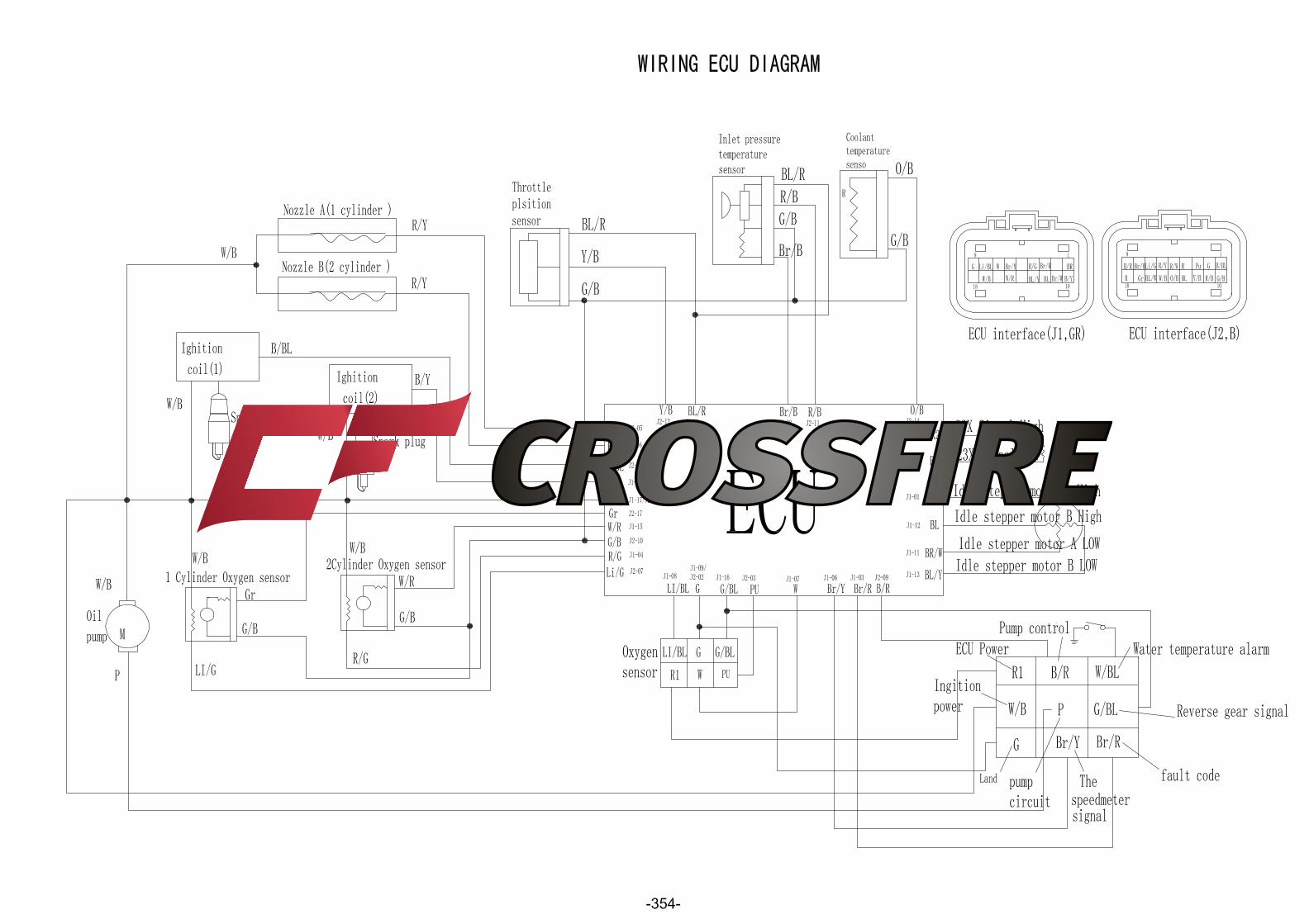
ELECTRICAL COMPONENTS - 302 - 9.Wiring connection • Check the connections of the entire ignition system. Refer to “CIRCUIT DIAGRAM”. CORRECT Replace the ECU unit ELECTRIC STARTING SYSTEM CIRCUIT DIAGRAM(see 356 page) POOR CONNECTION Properly connect the ignition system.
Transcript
ELECTRICAL COMPONENTS
- 302 -
9.Wiring connection
• Check the connections of the entire ignition
system. Refer to “CIRCUIT DIAGRAM”.
CORRECT
Replace the ECU unit
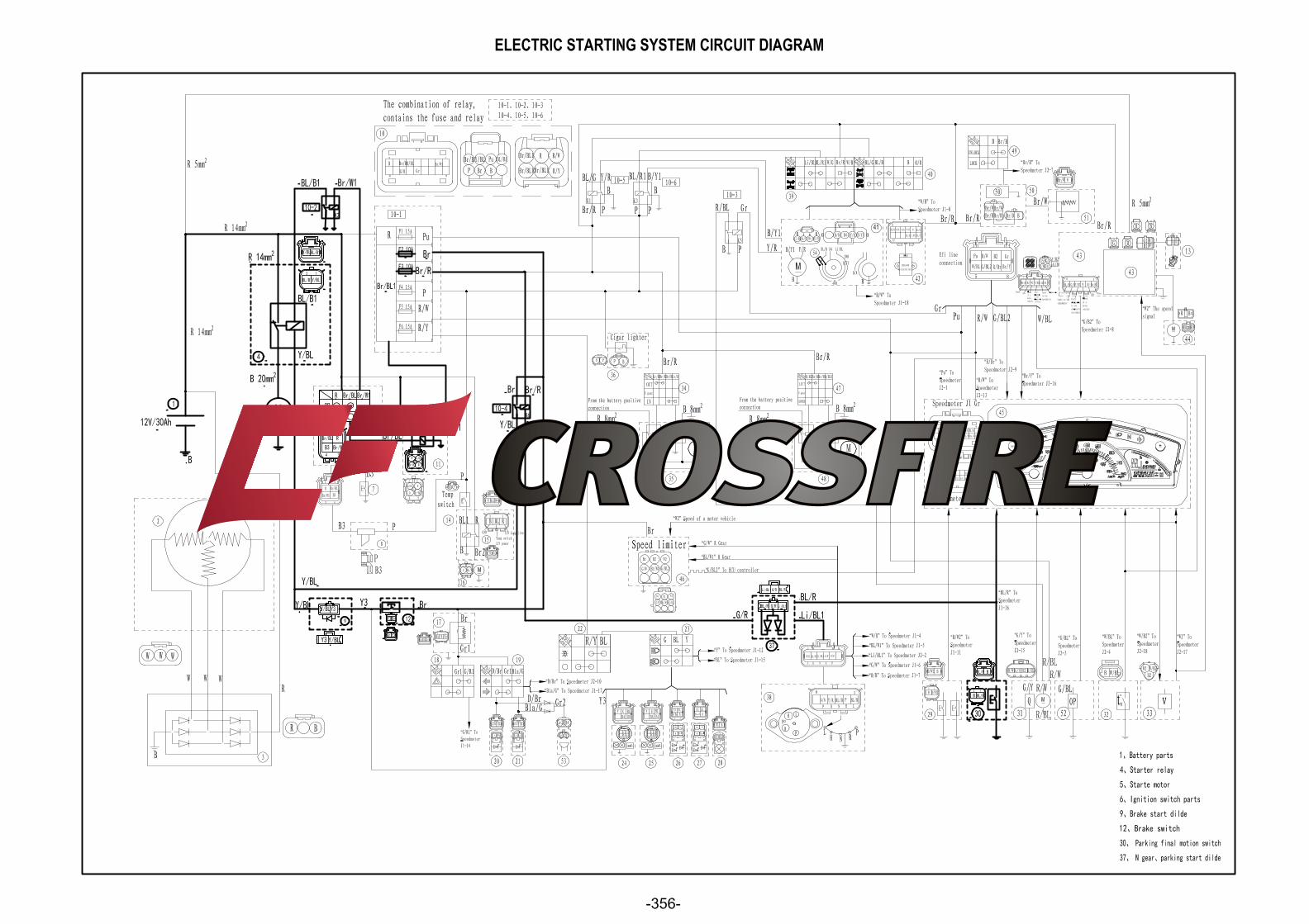
ELECTRIC STARTING SYSTEM
CIRCUIT DIAGRAM(see 356 page)
POOR CONNECTION
Properly connect the ignition system.
ELECTRICAL COMPONENTS
- 303 -
Procedure
Check:
1. Fuses (main, ignition, signaling system)
2. Battery
3. Starter motor
4. Starter relay
5. Main switch
1. Fuses (main, ignition, signaling system)
Refer to “CHECKING THE SWITCH”
CONTINUITY
2. Battery
• Check the battery condition. Refer to
“CHECKING AND CHARGING THE
BATTERY” in chapter 3.
Open-circuit voltage
12.8 V or more at 20 °C (68 °F)
CORRECT
3. Starter motor
• Connect the battery (+) terminal ① and
starter motor cable ② using a jumper lead③
• Check the operation of the starter motor.
6. Gear position switch
7. Brake light switch
8. Diode 1
9. Wiring connection (the entire starting system) NOTE: • Remove the following part(s) before
troubleshooting:
1. Console
2. Front frame
3. Front fender
• Use the following special tool(s) for
troubleshooting.
NO CONTINUITY
INCORRECT
WARNING: • A wire that is used as a jumper lead must
have the equivalent capacity or more as that
of the battery lead, otherwise the jumper
lead may burn.
• This check is likely to produce sparks, so
be sure that no flammable gas or fluid is in
the vicinity. DOSE NOT TURN
Replace the fuse(s).
• Clean the battery terminals.
• Recharge or replace the battery.
TROUBLESHOOTING
IF THE STARTER MOTOR FAILS TO OPERATE:
ELECTRICAL COMPONENTS
- 304 -
TURNS
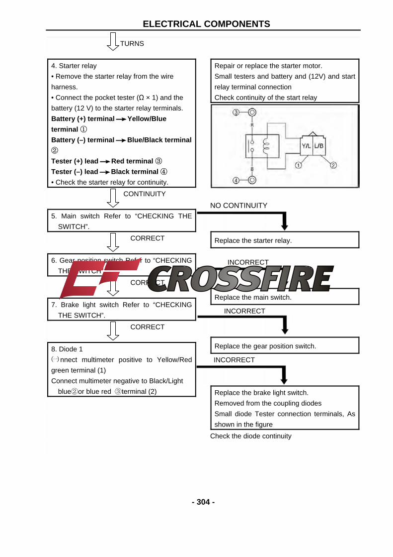
4. Starter relay
• Remove the starter relay from the wire
harness.
• Connect the pocket tester (Ω × 1) and the
battery (12 V) to the starter relay terminals.
Battery (+) terminal Yellow/Blue
terminal ①
Battery (–) terminal Blue/Black terminal
②
Tester (+) lead Red terminal ③
Tester (–) lead Black terminal ④
• Check the starter relay for continuity.
CONTINUITY
5. Main switch Refer to “CHECKING THE
SWITCH”.
CORRECT
6. Gear position switch Refer to “CHECKING
THE SWITCH”.
CORRECT
7. Brake light switch Refer to “CHECKING
THE SWITCH”.
CORRECT
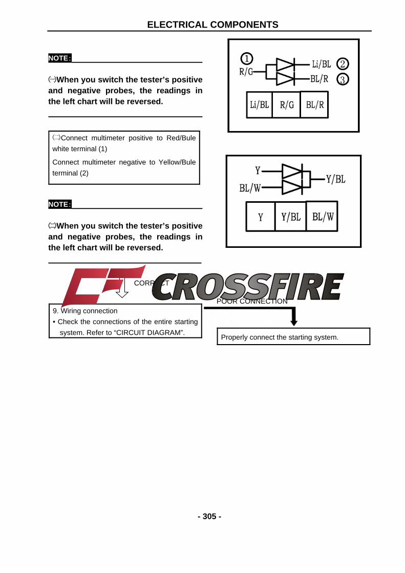
8. Diode 1
㈠nnect multimeter positive to Yellow/Red
green terminal (1)
Connect multimeter negative to Black/Light
blue②or blue red ③terminal (2)
Repair or replace the starter motor.
Small testers and battery and (12V) and start
relay terminal connection
Check continuity of the start relay
NO CONTINUITY
Replace the starter relay.
INCORRECT
Replace the main switch.
INCORRECT
Replace the gear position switch.
INCORRECT
Replace the brake light switch.
Removed from the coupling diodes
Small diode Tester connection terminals, As
shown in the figure
Check the diode continuity
ELECTRICAL COMPONENTS
- 305 -
NOTE: ㈠When you switch the tester’s positiveand negative probes, the readings inthe left chart will be reversed.
㈡Connect multimeter positive to Red/Bule
white terminal (1)
Connect multimeter negative to Yellow/Bule
terminal (2)
NOTE: ㈡When you switch the tester’s positiveand negative probes, the readings inthe left chart will be reversed.
CORRECT
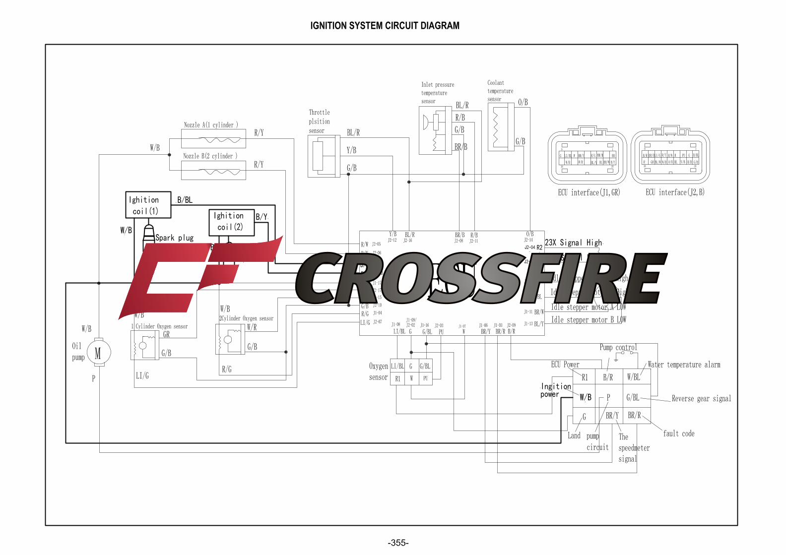
9. Wiring connection
• Check the connections of the entire starting
system. Refer to “CIRCUIT DIAGRAM”.
POOR CONNECTION
Properly connect the starting system.
ELECTRICAL COMPONENTS
- 306 -
STARTER MOTOR
No. Part Name Qty Remarks 1 2
Removing the starter motor Flange bolt Starter motor assy.
1
Remove the parts in the order listed
ELECTRICAL COMPONENTS
- 307 -
CHARGING SYSTEM CIRCUIT DIAGRAM
ELECTRICAL COMPONENTS
- 308 -
Procedure
Check:
1. Fuse (main)
2. Battery
3. Charging voltage
1. Fuse (main)
Refer to “CHECKING THE SWITCH”.
CONTINUITY
2.Battery
• Check the battery condition. Refer to
“CHECKING AND CHARGING THE
BATTERY in chapter 3.
Open-circuit voltage
12.8 V or more at 20 °C (68 °F)
CORRECT
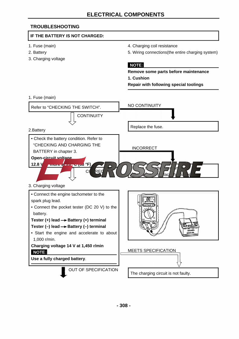
3. Charging voltage
• Connect the engine tachometer to the
spark plug lead.
• Connect the pocket tester (DC 20 V) to the
battery.
Tester (+) lead Battery (+) terminal
Tester (–) lead Battery (–) terminal
• Start the engine and accelerate to about
1,000 r/min.
Charging voltage 14 V at 1,450 r/min
NOTE: Use a fully charged battery.
OUT OF SPECIFICATION
4. Charging coil resistance
5. Wiring connections(the entire charging system)
NOTE: Remove some parts before maintenance
1. Cushion
Repair with following special toolings
NO CONTINUITY
Replace the fuse.
INCORRECT
• Clean the battery terminals.
• Recharge or replace the battery.
MEETS SPECIFICATION
The charging circuit is not faulty.
TROUBLESHOOTING
IF THE BATTERY IS NOT CHARGED:
ELECTRICAL COMPONENTS
- 309 -
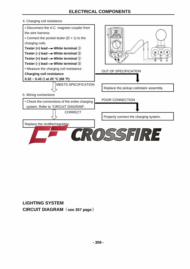
4. Charging coil resistance
• Disconnect the A.C. magneto coupler from
the wire harness.
• Connect the pocket tester (Ω × 1) to the
charging coils.
Tester (+) lead White terminal ①
Tester (–) lead White terminal ②
Tester (+) lead White terminal ①
Tester (–) lead White terminal ③
• Measure the charging coil resistance.
Charging coil resistance
0.32 ~ 0.43 Ω at 20 °C (68 °F)
MEETS SPECIFICATION
5. Wiring connections
• Check the connections of the entire charging
system. Refer to “CIRCUIT DIAGRAM”.
CORRECT
Replace the rectifier/regulator.
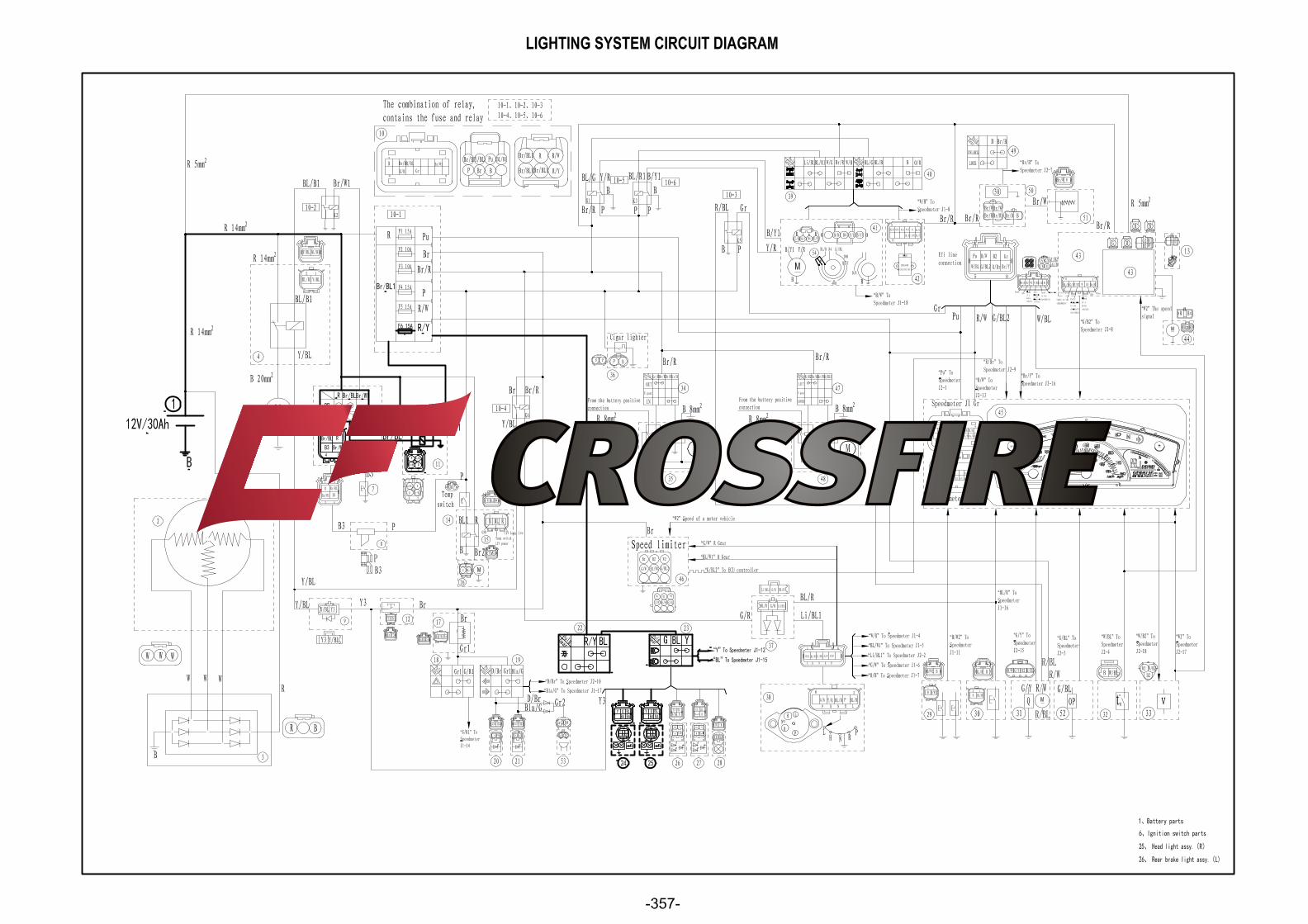
LIGHTING SYSTEM CIRCUIT DIAGRAM(see 357 page)
OUT OF SPECIFICATION
Replace the pickup coil/stator assembly.
POOR CONNECTION
Properly connect the charging system.
ELECTRICAL COMPONENTS
- 310 -
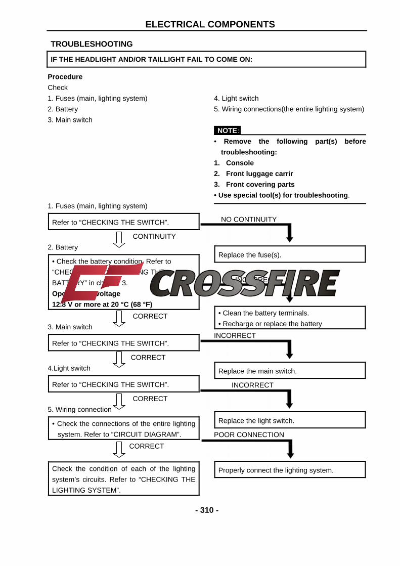
Procedure
Check
1. Fuses (main, lighting system)
2. Battery
3. Main switch
1. Fuses (main, lighting system)
Refer to “CHECKING THE SWITCH”.
CONTINUITY 2. Battery
• Check the battery condition. Refer to
“CHECKING AND CHARGING THE
BATTERY” in chapter 3.
Open-circuit voltage
12.8 V or more at 20 °C (68 °F)
CORRECT
3. Main switch
Refer to “CHECKING THE SWITCH”.
CORRECT 4.Light switch
Refer to “CHECKING THE SWITCH”.
CORRECT 5. Wiring connection
• Check the connections of the entire lighting
system. Refer to “CIRCUIT DIAGRAM”.
CORRECT
Check the condition of each of the lighting
system’s circuits. Refer to “CHECKING THE
LIGHTING SYSTEM”.
4. Light switch
5. Wiring connections(the entire lighting system)
NOTE: • Remove the following part(s) before
troubleshooting:
1. Console
2. Front luggage carrir
3. Front covering parts
• Use special tool(s) for troubleshooting.
NO CONTINUITY
Replace the fuse(s).
INCORRECT
• Clean the battery terminals.
• Recharge or replace the battery
INCORRECT
Replace the main switch.
INCORRECT
Replace the light switch.
POOR CONNECTION
Properly connect the lighting system.
TROUBLESHOOTING
IF THE HEADLIGHT AND/OR TAILLIGHT FAIL TO COME ON:
ELECTRICAL COMPONENTS
- 311 -
CHECKING THE LIGHTING SYSTEM 1. If the headlights fail to come on:
(1). Bulb and bulb socket
• Check the bulb and bulb socket for
continuity.
CONTINUITY
(2). Voltage
• Connect the pocket tester (DC 20 V) to the
headlight couplers.
Tester (+) lead
Black terminal ① or Yellow terminal ②
Tester (–) lead Green terminal ③
A When the light switch is on “ ”.
B When the light switch is on “ ”
• Turn the main switch to “ON”.
• Turn the light switch to “ ” or “ ”.
• Check the voltage (12 V) of the “Green” and
“Yellow” leads on the bulb socket
connector.
MEETS SPECIFICATION
This circuit is not faulty.
NO CONTINUITY
Replace the bulb and/or bulb socket.
A
B
OUT OF SPECIFICATION
The wiring circuit from the main switch to the
bulb socket connector is faulty, repair it.
ELECTRICAL COMPONENTS
- 312 -
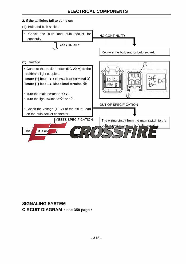
2. If the taillights fail to come on:
(1). Bulb and bulb socket
• Check the bulb and bulb socket for
continuity.
CONTINUITY
(2) . Voltage
• Connect the pocket tester (DC 20 V) to the
tail/brake light couplers.
Tester (+) lead Yellow1 lead terminal ①
Tester (–) lead Black lead terminal ②
• Turn the main switch to “ON”.
• Turn the light switch to“ ” or “ ”.
• Check the voltage (12 V) of the “Blue” lead
on the bulb socket connector.
MEETS SPECIFICATION
This circuit is not faulty.
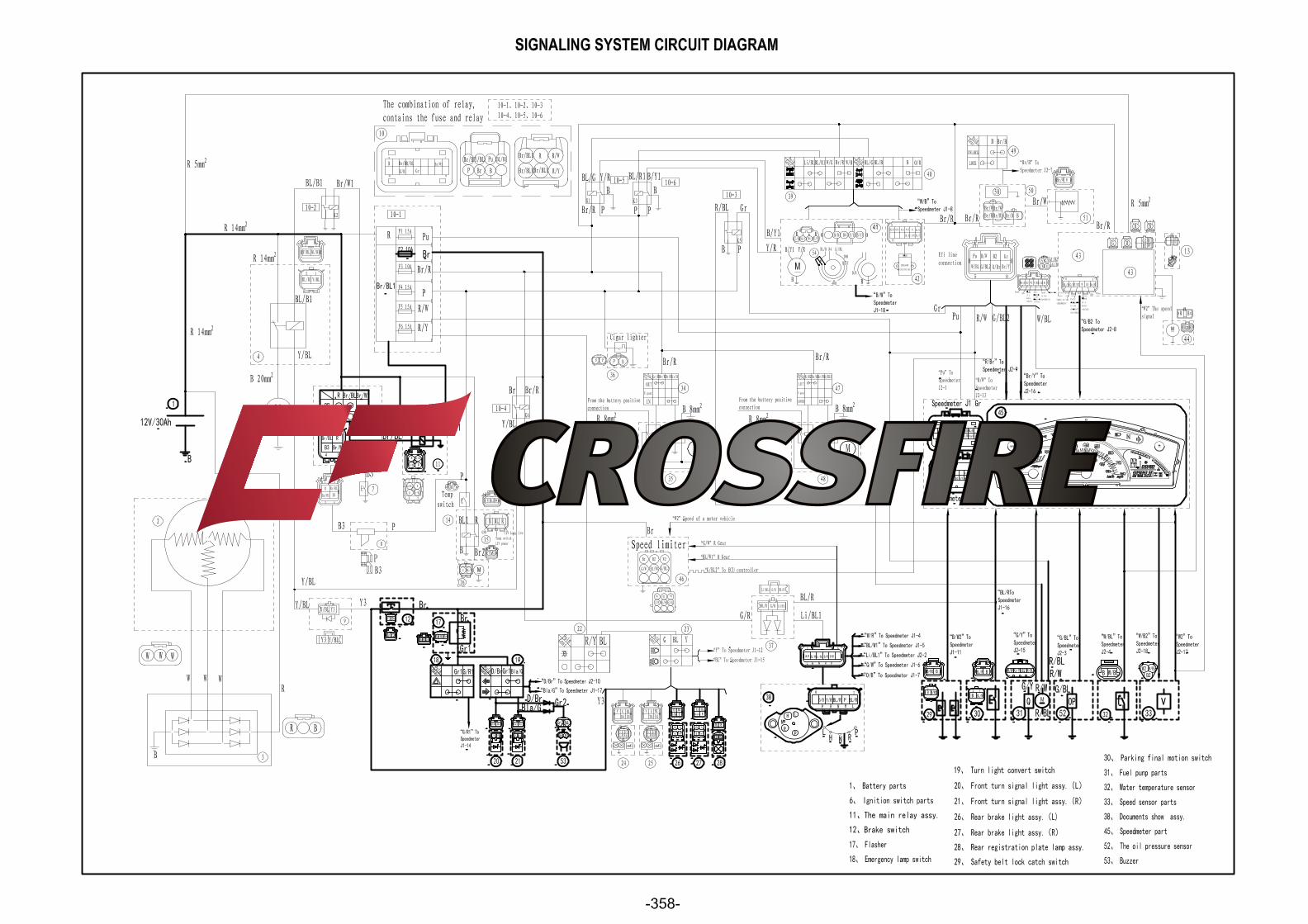
SIGNALING SYSTEM CIRCUIT DIAGRAM(see 358 page)
NO CONTINUITY
Replace the bulb and/or bulb socket.
OUT OF SPECIFICATION
The wiring circuit from the main switch to the
bulb socket connector is faulty, repair it.
ELECTRICAL COMPONENTS
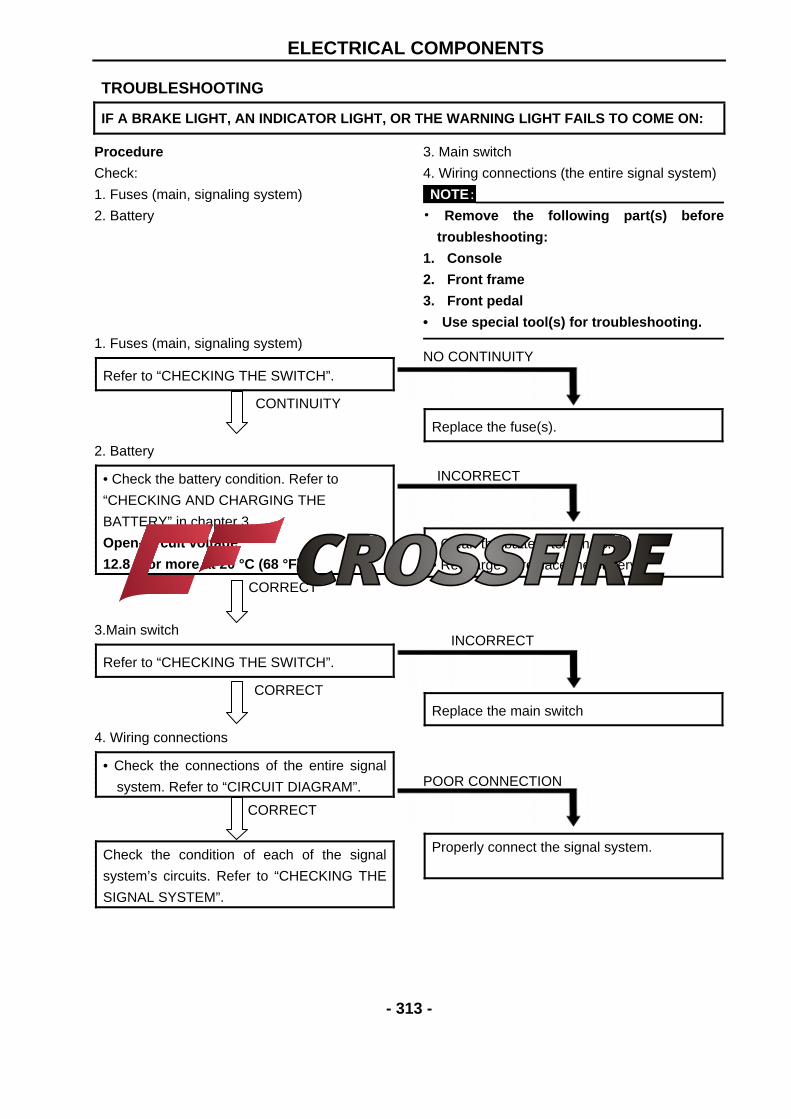
- 313 -
Procedure
Check:
1. Fuses (main, signaling system)
2. Battery
1. Fuses (main, signaling system)
Refer to “CHECKING THE SWITCH”.
CONTINUITY
2. Battery
• Check the battery condition. Refer to
“CHECKING AND CHARGING THE
BATTERY” in chapter 3.
Open-circuit voltage
12.8 V or more at 20 °C (68 °F)
CORRECT
3.Main switch
Refer to “CHECKING THE SWITCH”.
CORRECT
4. Wiring connections
• Check the connections of the entire signal
system. Refer to “CIRCUIT DIAGRAM”.
CORRECT
Check the condition of each of the signal
system’s circuits. Refer to “CHECKING THE
SIGNAL SYSTEM”.
3. Main switch
4. Wiring connections (the entire signal system)
NOTE: • Remove the following part(s) before
troubleshooting:
1. Console
2. Front frame
3. Front pedal
• Use special tool(s) for troubleshooting. NO CONTINUITY
Replace the fuse(s).
INCORRECT
• Clean the battery terminals.
• Recharge or replace the battery.
INCORRECT
Replace the main switch
POOR CONNECTION
Properly connect the signal system.
TROUBLESHOOTING
IF A BRAKE LIGHT, AN INDICATOR LIGHT, OR THE WARNING LIGHT FAILS TO COME ON:
ELECTRICAL COMPONENTS
- 314 -
CHECKING THE SIGNAL SYSTEM 1. If the brake lights fail to come on: (1). Bulb and bulb socket
• Check the bulb and bulb socket for
continuity.
CONTINUITY
(2). Bake light switch
Refer to “CHECKING THE SWITCH”.
CONTINUITY
(3). Voltage
• Connect the pocket tester (DC 20 V) to the
bulb socket connector.
Tester (+) lead Dark/Brown terminal ①
Tester (–) lead Black terminal ②
• Turn the main switch to “ON”.
• Turn the light switch to “ ” or “ ”.
• Check the voltage (12 V) of the “Yellow”
lead on the bulb socket connector.
MEETS SPECIFICATION
This circuit is not faulty.
NO CONTINUITY
Replace the bulb and/or bulb socket.
NO CONTINUITY
Replace the brake light switch.
OUT OF SPECIFICATION
The wiring circuit from the main switch to the
bulb socket connector is faulty, repair it.
ELECTRICAL COMPONENTS
- 315 -
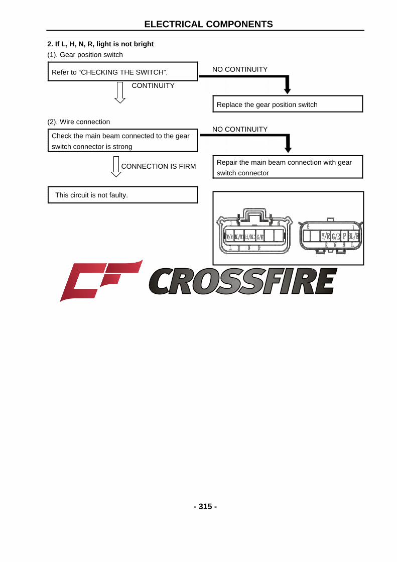
2. If L, H, N, R, light is not bright
(1). Gear position switch
Refer to “CHECKING THE SWITCH”.
CONTINUITY
(2). Wire connection
Check the main beam connected to the gear
switch connector is strong
CONNECTION IS FIRM
This circuit is not faulty.
NO CONTINUITY
Replace the gear position switch
NO CONTINUITY
Repair the main beam connection with gear
switch connector
ELECTRICAL COMPONENTS
- 316 -
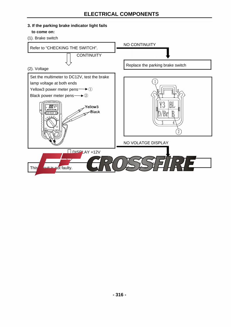
3. If the parking brake indicator light fails
to come on:
(1). Brake switch
Refer to “CHECKING THE SWITCH”.
CONTINUITY
(2). Voltage
Set the multimeter to DC12V, test the brake
lamp voltage at both ends
Yellow3 power meter pens ①
Black power meter pens ②
DISPLAY +12V
This circuit is not faulty.
NO CONTINUITY
Replace the parking brake switch
NO VOLATGE DISPLAY
Replace the fuse F2
ELECTRICAL COMPONENTS
- 317 -
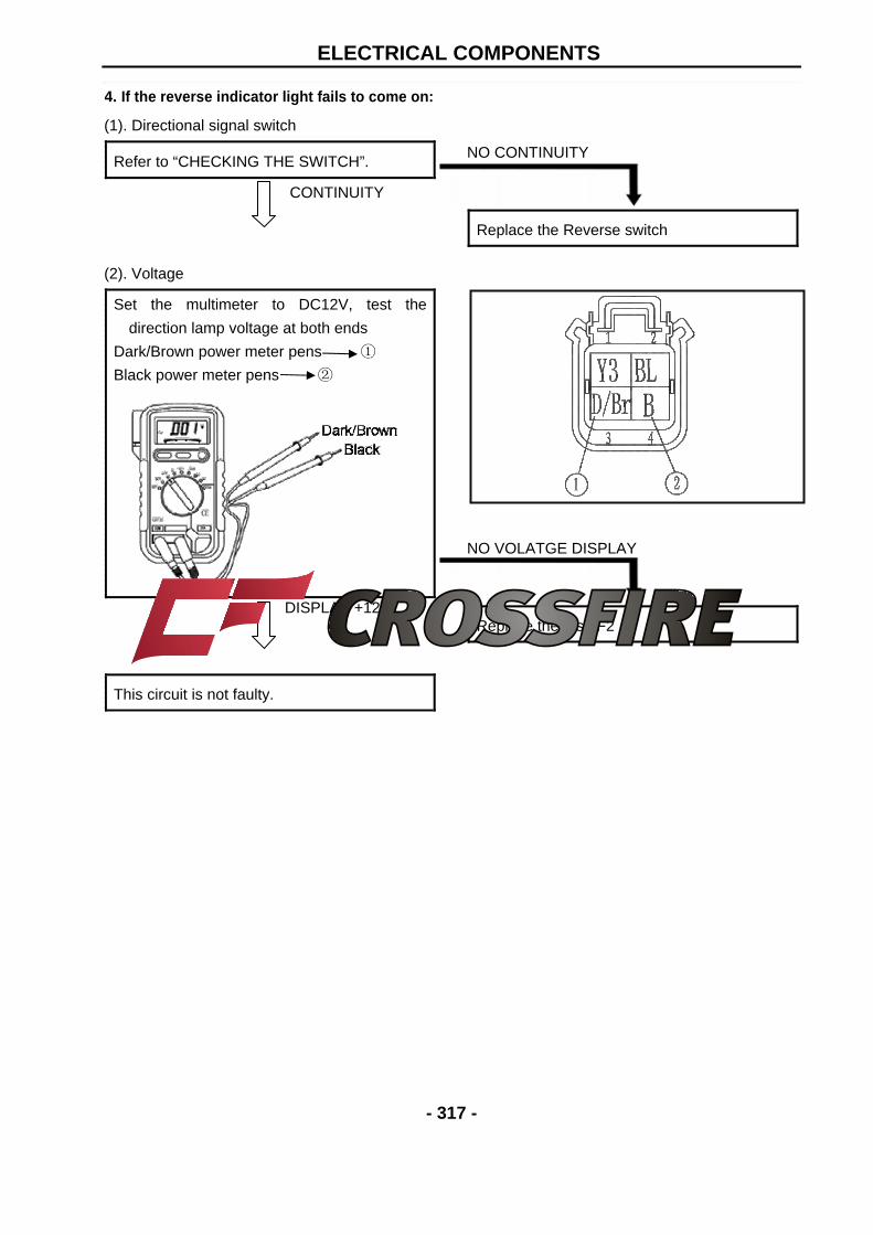
4. If the reverse indicator light fails to come on:
(1). Directional signal switch
Refer to “CHECKING THE SWITCH”.
CONTINUITY
(2). Voltage
Set the multimeter to DC12V, test the
direction lamp voltage at both ends
Dark/Brown power meter pens ①
Black power meter pens ②
DISPLAY +12V
This circuit is not faulty.
NO CONTINUITY
Replace the Reverse switch
NO VOLATGE DISPLAY
Replace the fuse F2
ELECTRICAL COMPONENTS
- 318 -
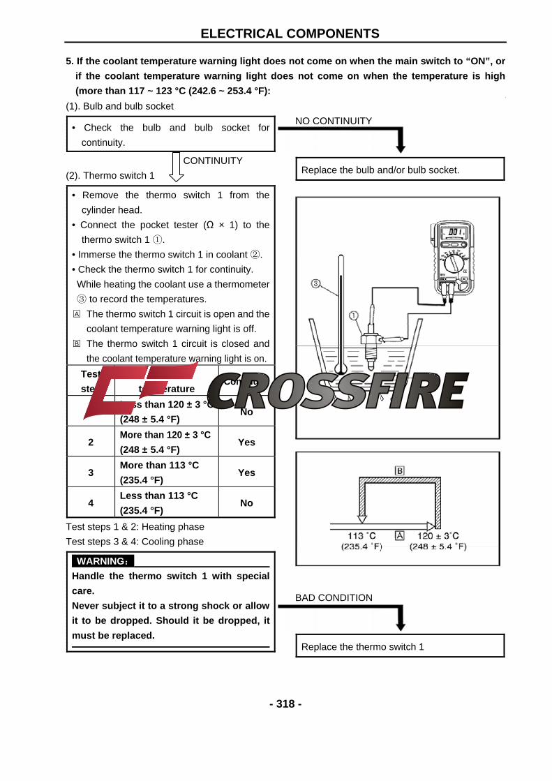
5. If the coolant temperature warning light does not come on when the main switch to “ON”, or
if the coolant temperature warning light does not come on when the temperature is high
(more than 117 ~ 123 °C (242.6 ~ 253.4 °F):
(1). Bulb and bulb socket
• Check the bulb and bulb socket for
continuity.
CONTINUITY
(2). Thermo switch 1
• Remove the thermo switch 1 from the
cylinder head.
• Connect the pocket tester (Ω × 1) to the
thermo switch 1 ①.
• Immerse the thermo switch 1 in coolant ②.
• Check the thermo switch 1 for continuity.
While heating the coolant use a thermometer
③ to record the temperatures.
A The thermo switch 1 circuit is open and the
coolant temperature warning light is off.
B The thermo switch 1 circuit is closed and
the coolant temperature warning light is on.
Test
step
Coolant
temperature Continuity
1 Less than 120 ± 3 °C
(248 ± 5.4 °F) No
2 More than 120 ± 3 °C
(248 ± 5.4 °F) Yes
3 More than 113 °C
(235.4 °F) Yes
4 Less than 113 °C
(235.4 °F) No
Test steps 1 & 2: Heating phase
Test steps 3 & 4: Cooling phase
WARNING: Handle the thermo switch 1 with special
care. Never subject it to a strong shock or allow
it to be dropped. Should it be dropped, it
must be replaced.
NO CONTINUITY
Replace the bulb and/or bulb socket.
BAD CONDITION
Replace the thermo switch 1
ELECTRICAL COMPONENTS
- 319 -
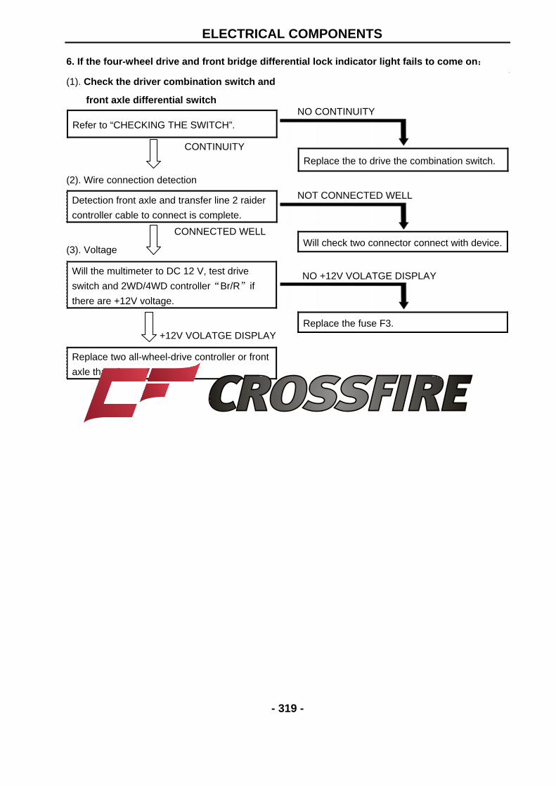
6. If the four-wheel drive and front bridge differential lock indicator light fails to come on:
(1). Check the driver combination switch and
front axle differential switch
Refer to “CHECKING THE SWITCH”.
CONTINUITY
(2). Wire connection detection
CONNECTED WELL
(3). Voltage
+12V VOLATGE DISPLAY
Detection front axle and transfer line 2 raider
controller cable to connect is complete.
Will the multimeter to DC 12 V, test drive
switch and 2WD/4WD controller“Br/R”if
there are +12V voltage.
Replace two all-wheel-drive controller or front
axle thansfer.
NO CONTINUITY
Replace the to drive the combination switch.
NOT CONNECTED WELL
NO +12V VOLATGE DISPLAY
Will check two connector connect with device.
Replace the fuse F3.
ELECTRICAL COMPONENTS
- 320 -
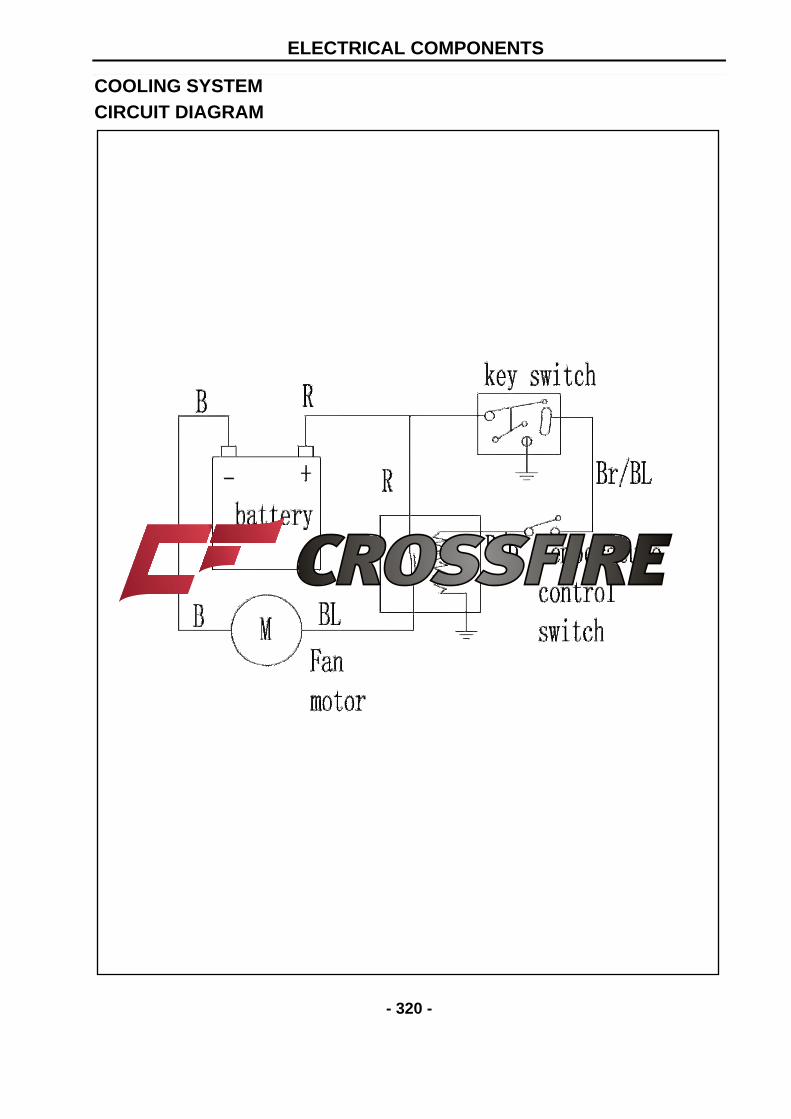
COOLING SYSTEM CIRCUIT DIAGRAM
ELECTRICAL COMPONENTS
- 321 -
TROUBLESHOOTING
IF THE FAN MOTOR DOES NOT MOVE:
Procedure Check:
1. Fuse (main)
2. Battery
3. Main switch
4. Radiator fan motor
1. Fuse (main)
Refer to “CHECKING THE SWITCH”.
CONTINUITY
2. Battery
• Check the battery condition. Refer to
“CHECKING AND CHARGING THE
BATTERY” in chapter 3。
Open-circuit voltage:
12.8 V or more at 20 °C (68 °F)
CORRECT
3. Main switch
Refer to “CHECKING THE SWITCH”.
CORRECT
5. Thermo switch 3
6. Wiring connection(the entire cooling system)
NOTE: • Remove the following part(s) before
troubleshooting.
1. Console
2. Front frame
3. Front pedal
• Use special tool(s) for troubleshooting. NO CONTINUITY
Replace the fuse.
INCORRECT
• Clean the battery terminals.
• Recharge or replace the battery
INCORRECT
Replace the main switch.
ELECTRICAL COMPONENTS
- 322 -
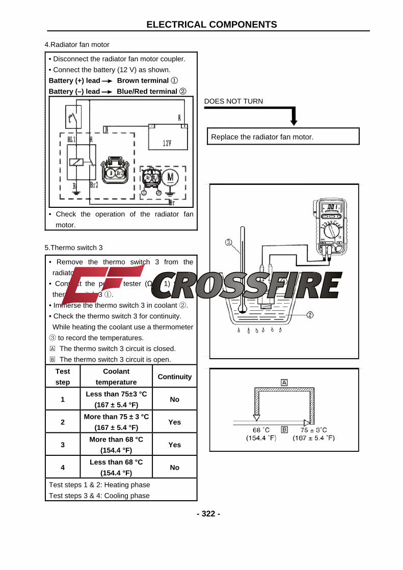
4.Radiator fan motor
• Disconnect the radiator fan motor coupler.
• Connect the battery (12 V) as shown.
Battery (+) lead Brown terminal ①
Battery (–) lead Blue/Red terminal ②
• Check the operation of the radiator fan
motor.
5.Thermo switch 3
• Remove the thermo switch 3 from the
radiator.
• Connect the pocket tester (Ω × 1) to the
thermo switch 3 ①.
• Immerse the thermo switch 3 in coolant ②.
• Check the thermo switch 3 for continuity.
While heating the coolant use a thermometer
③ to record the temperatures.
A The thermo switch 3 circuit is closed.
B The thermo switch 3 circuit is open.
Test
step
Coolant
temperature Continuity
1 Less than 75±3 °C
(167 ± 5.4 °F) No
2 More than 75 ± 3 °C
(167 ± 5.4 °F) Yes
3 More than 68 °C
(154.4 °F) Yes
4 Less than 68 °C
(154.4 °F) No
Test steps 1 & 2: Heating phase
Test steps 3 & 4: Cooling phase
DOES NOT TURN
Replace the radiator fan motor.
ELECTRICAL COMPONENTS
- 323 -
WARNING: Handle the thermo switch 3 with special
care.
Never subject it to a strong shock or allow
it to be dropped. Should it be dropped, it
must be replaced. Thermo switch 3
28 Nm (2.8 m · kg, 20 ft · lb)
GOOD CONDITION
6. Wiring connection
• Check the connections of the entire starting
system. Refer to “CIRCUIT DIAGRAM”
CORRECT
This circuit is not faulty.
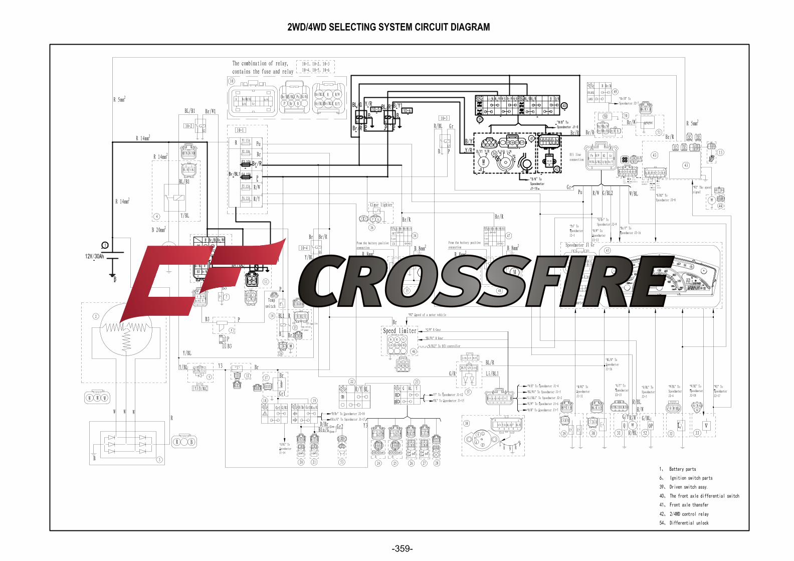
2WD/4WD SELECTING SYSTEM
CIRCUIT DIAGRAM(see 359 page)
BAD CONDITION
Replace the thermo switch 3
POOR CONNECTION
Properly connect the cooling system.
ELECTRICAL COMPONENTS
- 324 -
TROUBLESHOOTING
1. Check if the 2/4WD switch is working.
a. Turn on the switch, put the gear to position N; keep front and rear wheel off the ground , and then
roll the front wheel to see if the rear wheel is moving together with it or if it is rotatable.
b. After the actions above being done, and the wheels are rotatable, please check the electricity with
multimeter, if has no electricity, please check the fuse.
2. Check if the rear differential is working.
a. Check the sound. When the switch is turned on, the magneto valve will make s sound ‘TA’ to
show that it is working and the rear wheel won’t be able to rotatable at the same direction.
b. If no sound is made, check if the controller of magnetic valve has a output of 12V electricity, and
check if the magnetic valve has a input of 12V electricity,if it has the input, it means the valve doesn't
work, please change for a new one ; if not , please check if the input end of controller has a input, if it
has, change for a new controller, if not , check the fuse.
ENGINE MANAGEMENT SYSTEM
- 325 -
INTRODUCTION
EMS (Engine Management System)
EMS is a self contained set of components including a custom built computer and sensors and
actuators which control the operation of an engine by monitoring the engine speed, load and
temperature and providing the ignition spark at the right time for the prevailing conditions and
metering the fuel to the engine in the exact quantity required.
Typical Components Of EMS(BUCKET)
1. Electronic Control Unit
2. Multec 3.5 Injectors
3.Throttle Body Assembly(with stepper motor)
4. Engine Coolant Temperature Sensor
5. Intake Air Pressure and Temperature Sensor
6. Oxygen Sensor
7. Ignition Coil
8. Fuel Pump Module
ENGINE MANAGEMENT SYSTEM
- 326 -
Typical Components Of EMS(BENCH)
1. Electronic Control Unit
2. Multec 3.5 Injectors
3.Throttle Body Assembly(with stepper motor)
4. Engine Coolant Temperature Sensor
5. Intake Air Pressure and Temperature Sensor
6. Oxygen Sensor
7. Ignition Coil
8. Fuel Pump Module
ENGINE MANAGEMENT SYSTEM
- 327 -
Layout of EMS Components
COMPONENTS OF EMS
Electronic Control Unit
1.Description & Working Principle The ECU continuously monitors the operating conditions of the engine through the system
sensors. It also provides the necessary computation, adaptability, and output control in order to
minimize the tailpipe emissions and fuel consumption, while optimizing vehicle drivability for all
operating conditions. The ECU also provides diagnosis when system malfunctions occur. 2.Handling – DOs & DONTs
Legend:
Dotted line indicates inputs
Solid line indicates outputs
ENGINE MANAGEMENT SYSTEM
- 328 -
ECU Handing ACTION REASON
DO NOT: Place the ECU close to the exhaust
pipe or Engine when removed
High temperature might reduce the life of the
ECU and also can damage the ECU
DO NOT: Place the ECU close to or pour
water, oil or any other liquids.
ECU is susceptible to water and liquids
DO NOT: Allow mud or other debris to
accumulate on the surface of the ECU
Having mud or debris accumulated on the
ECU casing reduces its heat dissipation
efficiency.
DO NOT: Apply any voltage relative to any
point to the ECU
Drastically affects the performance of the
ECU and may lead to ECU damage
DO NOT: Clean ECU with any solvent or any
corrosive liquid
Can damage the housing of the ECU
DO: Take extreme care that water droplets or
excess moisture should not fall on ECU
connectors
ECU connectors can get short and may
lead to ECU damage
DO: Clean the ECU with a moist cloth and
keep it dry
Prevents ECU damage
3.Installation requirements The ECU shall be mounted using M5 machined screws with a torque of 3.9Nm ± 10%. The
mounting surface should also be flat to avoid subjecting the base plate to unnecessary force and
warping the PCB.
4.Maintenance service and Repair
ECU is a non-serviceable part. Once there are problems, it’s important to first determine if the
problem is caused by software/calibration. If it is caused by software/calibration, please refer to
software/calibration reflashing procedure. In the event of ECU hardware failure or malfunction
(during warranty period only) the ECU should be sent back to the vehicle manufacturer giving
complete details of the ECU Part No, Serial number, Vehicle Model & Make, manufacturing Date,
Total kms run on the vehicle, Location of use, Vehicle No, Date of return.
Multec 3.5 Injectors
1.Description and Working Principle The Multec 3.5 Fuel Injector is an electromechanical device. A magnetic field is generated as
voltage is applied to the solenoid coil. The resulting magnetic force lifts the core assembly,
overcoming manifold vacuum, spring force, and fuel pressure, allowing fuel to pass through the ball
and seat interface to the director. As the fuel passes through the director, an atomized spray is
developed. The injector closes when the voltage is removed, cutting off the fuel flow.
ENGINE MANAGEMENT SYSTEM
- 329 -
2.Handling - DOs & DONTs
3.5 FUEL INJECTOR HANDLING ACTION REASON
DO NOT: Re-use injector seal rings if at all
possible. If no other choice exists, take
extra care in inspecting the seal rings for
damage.
Leakage.
DO NOT: Dip injector tips into lubricants. Can plug injector spray orifices.
DO NOT: Cycle injector repeatedly without
fuel pressure.
Damage to internal mechanical components.
DO NOT: Pulse (actuate) a suspected high
leak rate injector (leak >50 sccm air).
Can dislodge internal contamination if
present and preclude root cause analysis.
DO NOT: Allow water to enter fuel system
from air lines, etc. during leak checks.
Can damage injectors.
DO NOT: Contact or apply load to the
injector tip for installation.
Apply load to 45 deg angle on nylon over
mold see
DO NOT: Pound injectors into manifold
during assembly to engine.
Can damage injectors or seal rings.
DO NOT: Apply excessive side loads to
electrical connectors.
May cause loss of electrical continuity.
DO NOT: Use any dropped unit. Internal damage may have occurred.
DONOT:Store injectors, rails, or
subassemblies including engines on which
the injectors have been installed in an
unprotected environment.
External contamination can damage the
injector electrically and/or mechanically.
DO NOT: Use the injector as a handle. Do not use the injector to lift assemblies
DO NOT: Rack, stage, or handle parts in a
manner that allows contact between parts.
Damage will occur.
DO NOT: Remove packing in a way that
allows contact between parts.
Damage could occur due ton contact
between parts.
DO NOT: Tap on fuel injectors to correct any
malfunction.
Can damage injector.
DO NOT: Replace the injector with other
part number not recommended for this
application
Will severely affect the performance of the
injector
DO: Take extra care when installing new
fuel seal ring over injector inlet flange.
Prevent tearing seal ring during installation.
ENGINE MANAGEMENT SYSTEM
- 330 -
DO: Use proper lubricants on seal ring
surfaces to install injector in engine.
Minimize time between applying lubricant
and inserting injector / rail.
Avoid damage to seal ring during installation.
Avoid contamination at seal.
DO: Pulse (actuate) stuck closed or tip-leak
suspected injector (Actuate consists of one
pulse <5 sec duration at 9 to 15V).
To verify the injector failure
DO: Pulse (actuate) injectors prior to a dry
fuel system leak test at engine/vehicle
assembly to reseat injector valves.
Injector valves may not reseat without fuel
after shipping and handling resulting in false
leakage.
DO: Avoid any liquid contamination in the
injector area.
Coil could short circuit.
DO: Use care during connection of
harness to injector.
Avoid terminal damage.
DO: Use recommended terminal lubricant
on mating connector.
Minimize potential for terminal fretting
corrosion.
DO: Return any dropped, damaged, or
suspect material with a tag that describes
the problem.
Ensure fast and correct diagnosis of root
cause.
3. Installation guidelines
Follow these guidelines to prevent damage to the injector and its electrical interface during the
replacement or re-installation process.
Lubrication: Apply a light coating of lubricant to the lower injector seal ring. ISO 10 light
mineral oil or equivalent is recommended.
The preferred technique is to apply the lubricant to the sockets the injectors are being
installed into, rather than directly to the seal ring itself. This will help minimize the
possibility of injector contamination.
Avoid applying lubricant over the director plate holes – this may restrict injector flow. Do
not dip the injector tip in lubricant.
Multec 3.5 injectors come from the factory with the seal rings attached. The re-use of seal
rings is not preferred when replacing an injector. If an injector is to be re-used, and no new
seal rings are available, take care to inspect each seal ring for signs of damage. Even
minor defects in the seal ring can lead to leakage. Take extra care in installing seal ring
over flange of injector inlet.
Carefully installing the harness connector will prevent terminal damage. Listen for a
positive audible click from the connector retention device — this ensures that it is fully
engaged. Shut off ignition.
Disconnect negative battery cable to avoid possible fuel discharge if an accidental attempt
is made to start the engine.
Disconnect the electrical connector from the injector wiring harness.
Relieve fuel pressure
Remove the retaining clip from the fuel injector.
ENGINE MANAGEMENT SYSTEM
- 331 -
Remove the fuel line connection from the injector
Carefully clean debris from the interface surfaces. Do not damage seal mating surfaces.
Remove the injector from the manifold
Apply a light coating of a lubricant to both the upper and lower injector seal ring of the
replacement injector.
Install the new injector into the manifold. Check that the injector is installed in the original
orientation to maintain proper spray targeting, and that the retaining clip is properly seated
on the injector and the fuel line
Install the retaining clip after connecting the fuel line
Tighten the injector mounting to the desired torque as mentioned in the manufacturer
manual
Tighten the fuel line
Re-install the injector electrical connector
Check for fuel leaks with the key “on” and the engine “off”
Start engine and verify proper operation.
or spray pattern, do not rotate the injector in the fuel rail assembly to install the injector
electrical connector. This may dislodge the retaining clip, and result in improper spray
orientation
4.Replacement Techniques
WARNING:
The injector and all associated hardware may be extremely hot. Shut off ignition.
Disconnect negative battery cable to avoid possible fuel discharge if an accidental attempt
is made to start the engine.
Disconnect the electrical connector from the injector wiring harness.
Relieve fuel pressure
Remove the retaining clip from the fuel injector.
Remove the fuel line connection from the injector
Carefully clean debris from the interface surfaces. Do not damage seal mating surfaces.
Remove the injector from the manifold
Apply a light coating of a lubricant to both the upper and lower injector seal ring of the
replacement injector.
Install the new injector into the manifold. Check that the injector is installed in the original
orientation to maintain proper spray targeting, and that the retaining clip is properly seated
on the injector and the fuel line
Install the retaining clip after connecting the fuel line
Tighten the injector mounting to the desired torque as mentioned in the manufacturer
manual
Tighten the fuel line
Re-install the injector electrical connector
Check for fuel leaks with the key “on” and the engine “off”
Start engine and verify proper operation.
ENGINE MANAGEMENT SYSTEM
- 332 -
5.Plugging Fuel deposits cause plugging resulting in flow shifts over the life of the injector. Fuel varnish or
gumming, a type of injector deposit, is created when certain types of fuel are heated by high
injector tip temperatures at soak (no fuel flow). Deposit build up in the director holes causes
the flow shifts
Plugging can cause flow restrictions, frictional changes and the collection of other particles
attracted by the tacky surface. The flow restrictions can degrade emissions and drivability.
Other fuel and environmental conditions may cause crystal or corrosion growth in the
injector and cause a flow shift.
Oxidation stability of the gasoline affects the potential for deposit formation and must be
controlled by the fuel supplier.
Increased levels of detergent additives reduce the rate of injector plugging.
Incase of plugging of injector follow the injector cleaning procedure mentioned in the section
below
6.Cleaning Procedure Electrically disable the fuel pump by removing the fuel pump connection.
Relieve the fuel pressure in the system and disconnect the fuel connection at the injector.
Plug the fuel feed line.
Injector cleaner with the specific ratio of the cleaner and gasoline to be mixed in the Injector
cleaning tank.
Connect the injector-cleaning tank to injector in the vehicle.
Pressurize the injector-cleaning tank to system pressure.
Start and idle the engine for 15- 20 minutes.
Disconnect the injector-cleaning tank from the system and install the fuel pump connections.
Connect the fuel feed line to injector.
Start and idle the vehicle for an additional 2 minutes to ensure the residual injector cleaner
is flushed from system.
Throttle Body Assembly(with stepper motor)
1.Description and Working Principle The Throttle Body Assembly is an interactive system comprised of the following
subsystems: the main casting body, bearing system, shaft and valve system, return spring
system, cable interface system, throttle position sensing system, and the bypass air control
system. The subsystems interact and support each other to provide all the functional
requirements, which are mentioned below -
Control intake air flow
Control idle air flow
Sense throttle position - Provide position feedback to Engine Controller
Provide reactionary force to the throttle
ENGINE MANAGEMENT SYSTEM
- 333 -
2.Handling – DOs and DONTs
3.Throttle Body Removal Disconnect negative terminal of the battery
Disconnect electric lead wire of throttle position sensor coupler, stepper motor coupler and
MAP/MAT sensor coupler ( if this sensor is mounted on the throttle body)
Disconnect accelerator cable from throttle body
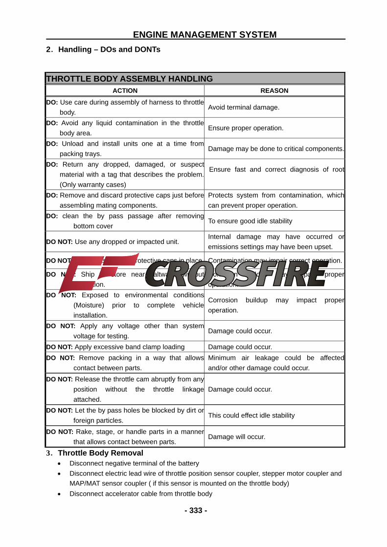
THROTTLE BODY ASSEMBLY HANDLING ACTION REASON
DO: Use care during assembly of harness to throttle
body. Avoid terminal damage.
DO: Avoid any liquid contamination in the throttle
body area. Ensure proper operation.
DO: Unload and install units one at a time from
packing trays. Damage may be done to critical components.
DO: Return any dropped, damaged, or suspect
material with a tag that describes the problem.
(Only warranty cases)
Ensure fast and correct diagnosis of root
DO: Remove and discard protective caps just before
assembling mating components.
Protects system from contamination, which
can prevent proper operation.
DO: clean the by pass passage after removing
bottom cover To ensure good idle stability
DO NOT: Use any dropped or impacted unit. Internal damage may have occurred or
emissions settings may have been upset.
DO NOT: Store units without protective caps in place. Contamination may impair correct operation.
DO NOT: Ship or store near saltwater without
protection.
Corrosion buildup may impact proper
operation.
DO NOT: Exposed to environmental conditions
(Moisture) prior to complete vehicle
installation.
Corrosion buildup may impact proper
operation.
DO NOT: Apply any voltage other than system
voltage for testing. Damage could occur.
DO NOT: Apply excessive band clamp loading Damage could occur.
DO NOT: Remove packing in a way that allows
contact between parts.
Minimum air leakage could be affected
and/or other damage could occur.
DO NOT: Release the throttle cam abruptly from any
position without the throttle linkage
attached.
Damage could occur.
DO NOT: Let the by pass holes be blocked by dirt or
foreign particles. This could effect idle stability
DO NOT: Rake, stage, or handle parts in a manner
that allows contact between parts. Damage will occur.
ENGINE MANAGEMENT SYSTEM
- 334 -
Remove air cleaner outlet hose and throttle body outlet hose
4.Cleaning Procedure If there is cover on the bottom, it may be removed and cleaned using carburetor cleaner (3M
make recommended). Once the throttle body cover is removed, spray the throttle-body cleaner
inside the shipping air passage, and use the brushes to gently dislodge the dirt, gum and
varnish that are present. Do not let the bye pass holes be blocked by dirt or foreign particles.
5.Throttle Body Installation Reverse the procedure for installation noting the following:
Adjust accelerator cable play
Check to ensure that all removed parts are back in place.Reinstall any necessary part which
have not been reinstalled
6.Precautions Do not submerge TPS in any cleaning fluid.
Always open the throttle valve using the throttle cable or lever.
Do not hold the valve at opening position by inserting tools or any sticks into the bore. The
valve may be warped and the bore may be scratched. This type of damage may keep the
throttle from opening easily or fully closing.
Engine Coolant Temperature Sensor
1.Description and Working Principle
This sensor is used in water cooled engines. It provides a resistance that varies as a function of
temperature within prescribed tolerance limits. The sensor has a negative temperature
coefficient of resistance. This is a non-serviceable part.
2.Installation Requirements Dynamic Torque Requirement: The sensor shall be hand into the application and then
driven by a driver with a maximum no load speed of 400 rpm or installed to the desired
torque by a hand torque wrench (5/8” hex). The recommended installation torque is:
Minimum: 20 N·m
Maximum: 25 N·m
Static Torque Requirement: The torque required to remove the sensor from the mating hole
shall be within 200% of the installation torque mentioned above.
3.Sample Cleaning When necessary the samples may be cleaned in isopropyl alcohol for one minute with
mating connectors in place and then air-dried
Intake Air Pressure and Temperature Sensor
1.Description and Working Principle
ENGINE MANAGEMENT SYSTEM
- 335 -
This sensor has two functions. The first is the intake manifold air temperature, it provides a
resistance that varies as a function of temperature within prescribed tolerance limits. The
second is the intake manifold air pressure; it provides a voltage varies as the intake air
pressure.
2.Sample Cleaning When necessary the samples may be cleaned in isopropyl alcohol or gasoline for one
minute with mating connectors in place and then air-dried
Oxygen Sensor
1.Description and Working Principle
This sensor is a device for monitoring the residual oxygen in the exhaust of an internal
combustion engine. It consists of the wide range sensor and stoichiometric sensor. Usually we
use stoichiometric sensor on the small engine. It is the feedback element for engine closed
loop control.
2.Installation Requirements Mounting Angle with Level: ≥10 degree
Tightening Torque Requirement: 40-60 Nm
Ignition Coil
1.Description and Working Principle
This coil provides energy to the spark plug in the combustion chamber. The coil itself doesn’t
have a driver. The high voltage tower of the coil is connected to the spark plug using a high
voltage cable assembly. This is a non-serviceable component.
2.Installation requirements The vehicle frame provides the mounting surface and mounting holes.
Mount coil close to the spark plug and keep the plug wire length very short (less than 6 “).
Mount coil away from any pick coil device. Especially, a VR type Crank / Cam sensor. Keep
a Min distance of 150 mm (around 6”) between coil and any VR sensor device.
Never route the coil C- wire with the same bundle as the Crank sensor wires. There is
around 200 V peak potential between C- wire and engine ground. This voltage potential
could cause a noise on sensor cables.
3.DOs and DONTs
Ignition Coil Handing
Action Reason
DO NOT: Install the low voltage connectors with
the power applied
This might cause an unwanted secondary firing,
possibly leading to personal injury
ENGINE MANAGEMENT SYSTEM
- 336 -
DO NOT: Use a screw driver to asset in removing
secondary boots from the secondary tower. Use
tools designed for secondary removal.
It is possible to damage a secondary lead in
such a manner that creates an electrical path to
outside the system permitting improper system
operation misfire, or even possible personal
injury if arcing occurs.
DO NOT: Use parts that have been dropped or
display physical damage
Damaged components can lead to premature
failure.
DO NOT: Scratch or apply any non approved
material to the surface of the high voltage tower
which mates with the high voltage secondary
leads.
This can jeopardize the seal integrity of the
mating surfaces which in turn can create a
secondary high voltage leak path.
DO NOT: Strike any part of the ignition system
with a tool or other object.
This can lead to physical damage which can
cause a system malfunction or failure.
DO NOT: Permit paint or other sprayed materials
to be sprayed onto the electrical connectors.
Insulating type sprays can create a high
resistance or open connection. And, a
conductive type spray can create an electrical
short condition.
DO NOT: Support the ignition system by the
wiring harness or plug wire.
These leads are not designed to support the
weight of the ignition system. It can create a
poor electrical connection Or become
disconnected allowing the system to fall and be
subjected to physical damage
DO NOT: Pierce or probe the secondary
leads.
This creates an electrical path to outside the
system permitting improper system operation,
misfire, or even possible personal injury if arcing
occurs.
DO NOT: Operate without the spark plug
attached.
If a technician or mechanic comes in contact
with the high voltage generated during
operation, personal injury may occur. Or, if the
engine is operated under this condition,
unburned fuel may fill the converter area
creating a potential hazard
DO NOT: Share ignition component wiring with
other components, Dedicated wiring is required.
This prevents electrical cross talking between
components which can lead to component
malfunction.
DO NOT: Apply voltage to the ignition system
other than vehicle system voltage for testing
purposes.
This can cause reduced performance or an
electrical malfunction of the ignition system.
DO NOT: Use high impact tools to apply the spark
plug boot to the ignition secondary towers.
Installation of the high voltage secondary leads
by hand is preferred.
Damage to the coil tower, secondary boot, or
mating connection surfaces might occur.
ENGINE MANAGEMENT SYSTEM
- 337 -
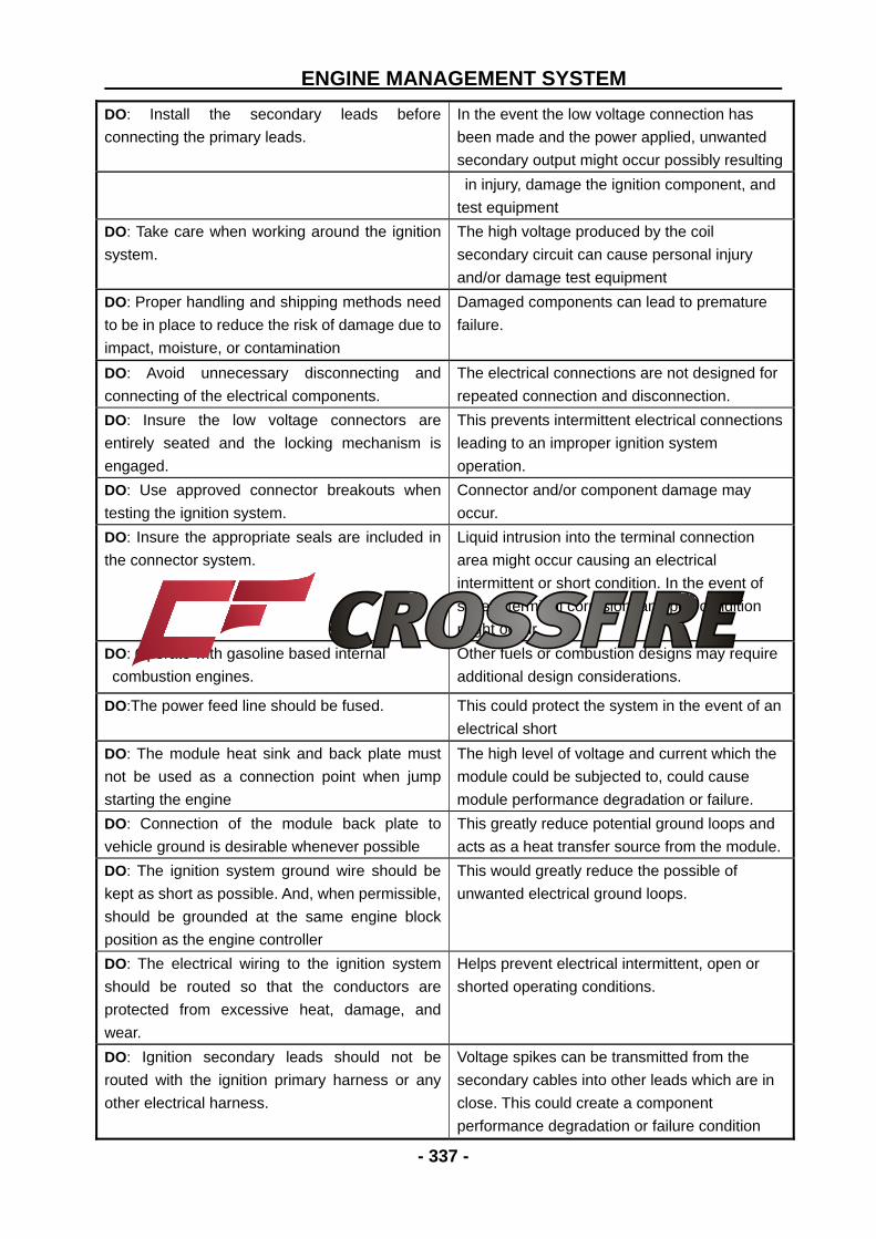
DO: Install the secondary leads before
connecting the primary leads.
In the event the low voltage connection has
been made and the power applied, unwanted
secondary output might occur possibly resulting
in injury, damage the ignition component, and
test equipment
DO: Take care when working around the ignition
system.
The high voltage produced by the coil
secondary circuit can cause personal injury
and/or damage test equipment
DO: Proper handling and shipping methods need
to be in place to reduce the risk of damage due to
impact, moisture, or contamination
Damaged components can lead to premature
failure.
DO: Avoid unnecessary disconnecting and
connecting of the electrical components.
The electrical connections are not designed for
repeated connection and disconnection.
DO: Insure the low voltage connectors are
entirely seated and the locking mechanism is
engaged.
This prevents intermittent electrical connections
leading to an improper ignition system
operation.
DO: Use approved connector breakouts when
testing the ignition system.
Connector and/or component damage may
occur.
DO: Insure the appropriate seals are included in
the connector system.
Liquid intrusion into the terminal connection
area might occur causing an electrical
intermittent or short condition. In the event of
severe terminal corrosion, an open condition
might occur.
DO: Operate with gasoline based internal
combustion engines.
Other fuels or combustion designs may require
additional design considerations.
DO:The power feed line should be fused. This could protect the system in the event of an
electrical short
DO: The module heat sink and back plate must
not be used as a connection point when jump
starting the engine
The high level of voltage and current which the
module could be subjected to, could cause
module performance degradation or failure.
DO: Connection of the module back plate to
vehicle ground is desirable whenever possible
This greatly reduce potential ground loops and
acts as a heat transfer source from the module.
DO: The ignition system ground wire should be
kept as short as possible. And, when permissible,
should be grounded at the same engine block
position as the engine controller
This would greatly reduce the possible of
unwanted electrical ground loops.
DO: The electrical wiring to the ignition system
should be routed so that the conductors are
protected from excessive heat, damage, and
wear.
Helps prevent electrical intermittent, open or
shorted operating conditions.
DO: Ignition secondary leads should not be
routed with the ignition primary harness or any
other electrical harness.
Voltage spikes can be transmitted from the
secondary cables into other leads which are in
close. This could create a component
performance degradation or failure condition
ENGINE MANAGEMENT SYSTEM
- 338 -
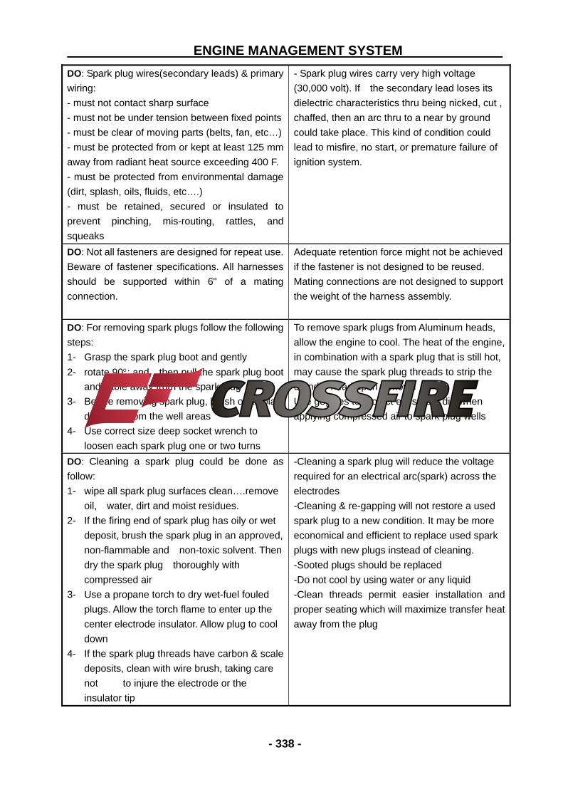
DO: Spark plug wires(secondary leads) & primary
wiring:
- must not contact sharp surface
- must not be under tension between fixed points
- must be clear of moving parts (belts, fan, etc…)
- must be protected from or kept at least 125 mm
away from radiant heat source exceeding 400 F.
- must be protected from environmental damage
(dirt, splash, oils, fluids, etc….)
- must be retained, secured or insulated to
prevent pinching, mis-routing, rattles, and
squeaks
- Spark plug wires carry very high voltage
(30,000 volt). If the secondary lead loses its
dielectric characteristics thru being nicked, cut ,
chaffed, then an arc thru to a near by ground
could take place. This kind of condition could
lead to misfire, no start, or premature failure of
ignition system.
DO: Not all fasteners are designed for repeat use.
Beware of fastener specifications. All harnesses
should be supported within 6" of a mating
connection.
Adequate retention force might not be achieved
if the fastener is not designed to be reused.
Mating connections are not designed to support
the weight of the harness assembly.
DO: For removing spark plugs follow the following
steps:
1- Grasp the spark plug boot and gently
2- rotate 90; and then pull the spark plug boot
and cable away from the spark plug
3- Before removing spark plug, brush or air blast
dirt away from the well areas
4- Use correct size deep socket wrench to
loosen each spark plug one or two turns
To remove spark plugs from Aluminum heads,
allow the engine to cool. The heat of the engine,
in combination with a spark plug that is still hot,
may cause the spark plug threads to strip the
cylinder head upon removal
Use goggles to protect eyes from dirt when
applying compressed air to spark plug wells
DO: Cleaning a spark plug could be done as
follow:
1- wipe all spark plug surfaces clean….remove
oil, water, dirt and moist residues.
2- If the firing end of spark plug has oily or wet
deposit, brush the spark plug in an approved,
non-flammable and non-toxic solvent. Then
dry the spark plug thoroughly with
compressed air
3- Use a propane torch to dry wet-fuel fouled
plugs. Allow the torch flame to enter up the
center electrode insulator. Allow plug to cool
down
4- If the spark plug threads have carbon & scale
deposits, clean with wire brush, taking care
not to injure the electrode or the
insulator tip
-Cleaning a spark plug will reduce the voltage
required for an electrical arc(spark) across the
electrodes
-Cleaning & re-gapping will not restore a used
spark plug to a new condition. It may be more
economical and efficient to replace used spark
plugs with new plugs instead of cleaning.
-Sooted plugs should be replaced
-Do not cool by using water or any liquid
-Clean threads permit easier installation and
proper seating which will maximize transfer heat
away from the plug
ENGINE MANAGEMENT SYSTEM
- 339 -
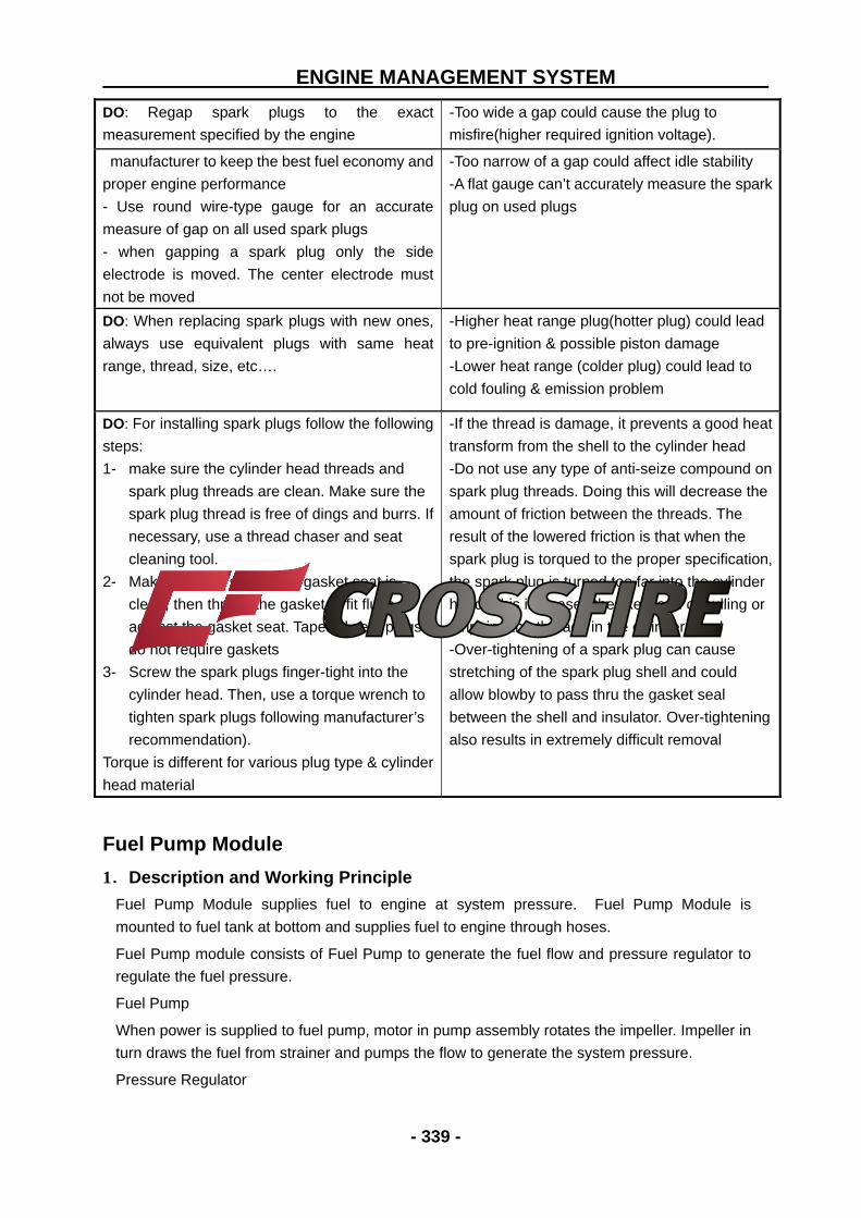
DO: Regap spark plugs to the exact
measurement specified by the engine
-Too wide a gap could cause the plug to
misfire(higher required ignition voltage).
manufacturer to keep the best fuel economy and
proper engine performance
- Use round wire-type gauge for an accurate
measure of gap on all used spark plugs
- when gapping a spark plug only the side
electrode is moved. The center electrode must
not be moved
-Too narrow of a gap could affect idle stability
-A flat gauge can’t accurately measure the spark
plug on used plugs
DO: When replacing spark plugs with new ones,
always use equivalent plugs with same heat
range, thread, size, etc….
-Higher heat range plug(hotter plug) could lead
to pre-ignition & possible piston damage
-Lower heat range (colder plug) could lead to
cold fouling & emission problem
DO: For installing spark plugs follow the following
steps:
1- make sure the cylinder head threads and
spark plug threads are clean. Make sure the
spark plug thread is free of dings and burrs. If
necessary, use a thread chaser and seat
cleaning tool.
2- Make sure the spark plug gasket seat is
clean, then thread the gasket to fit flush
against the gasket seat. Tapered seat plugs
do not require gaskets
3- Screw the spark plugs finger-tight into the
cylinder head. Then, use a torque wrench to
tighten spark plugs following manufacturer’s
recommendation).
Torque is different for various plug type & cylinder
head material
-If the thread is damage, it prevents a good heat
transform from the shell to the cylinder head
-Do not use any type of anti-seize compound on
spark plug threads. Doing this will decrease the
amount of friction between the threads. The
result of the lowered friction is that when the
spark plug is torqued to the proper specification,
the spark plug is turned too far into the cylinder
head. This increases the likelihood of pulling or
stripping the threads in the cylinder head
-Over-tightening of a spark plug can cause
stretching of the spark plug shell and could
allow blowby to pass thru the gasket seal
between the shell and insulator. Over-tightening
also results in extremely difficult removal
Fuel Pump Module
1.Description and Working Principle
Fuel Pump Module supplies fuel to engine at system pressure. Fuel Pump Module is
mounted to fuel tank at bottom and supplies fuel to engine through hoses.
Fuel Pump module consists of Fuel Pump to generate the fuel flow and pressure regulator to
regulate the fuel pressure.
Fuel Pump
When power is supplied to fuel pump, motor in pump assembly rotates the impeller. Impeller in
turn draws the fuel from strainer and pumps the flow to generate the system pressure.
Pressure Regulator
ENGINE MANAGEMENT SYSTEM
- 340 -
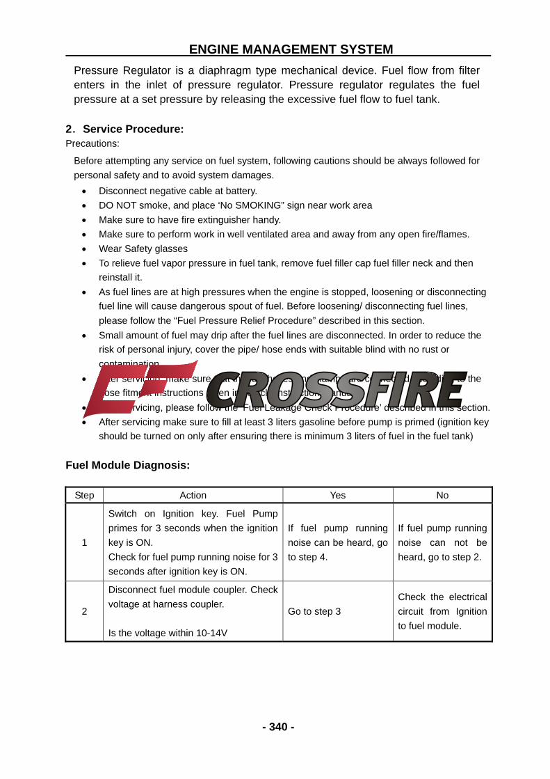
Pressure Regulator is a diaphragm type mechanical device. Fuel flow from filter enters in the inlet of pressure regulator. Pressure regulator regulates the fuel pressure at a set pressure by releasing the excessive fuel flow to fuel tank.
2.Service Procedure: Precautions:
Before attempting any service on fuel system, following cautions should be always followed for
personal safety and to avoid system damages.
Disconnect negative cable at battery.
DO NOT smoke, and place ‘No SMOKING” sign near work area
Make sure to have fire extinguisher handy.
Make sure to perform work in well ventilated area and away from any open fire/flames.
Wear Safety glasses
To relieve fuel vapor pressure in fuel tank, remove fuel filler cap fuel filler neck and then
reinstall it.
As fuel lines are at high pressures when the engine is stopped, loosening or disconnecting
fuel line will cause dangerous spout of fuel. Before loosening/ disconnecting fuel lines,
please follow the “Fuel Pressure Relief Procedure” described in this section.
Small amount of fuel may drip after the fuel lines are disconnected. In order to reduce the
risk of personal injury, cover the pipe/ hose ends with suitable blind with no rust or
contamination.
After servicing, make sure that the fuel hoses and clamps are connected according to the
hose fitment instructions given in vehicle instruction manual.
After servicing, please follow the ‘Fuel Leakage Check Procedure’ described in this section.
After servicing make sure to fill at least 3 liters gasoline before pump is primed (ignition key
should be turned on only after ensuring there is minimum 3 liters of fuel in the fuel tank)
Fuel Module Diagnosis:
Step Action Yes No
1
Switch on Ignition key. Fuel Pump
primes for 3 seconds when the ignition
key is ON.
Check for fuel pump running noise for 3
seconds after ignition key is ON.
If fuel pump running
noise can be heard, go
to step 4.
If fuel pump running
noise can not be
heard, go to step 2.
2
Disconnect fuel module coupler. Check
voltage at harness coupler.
Is the voltage within 10-14V
Go to step 3
Check the electrical
circuit from Ignition
to fuel module.
ENGINE MANAGEMENT SYSTEM
- 341 -
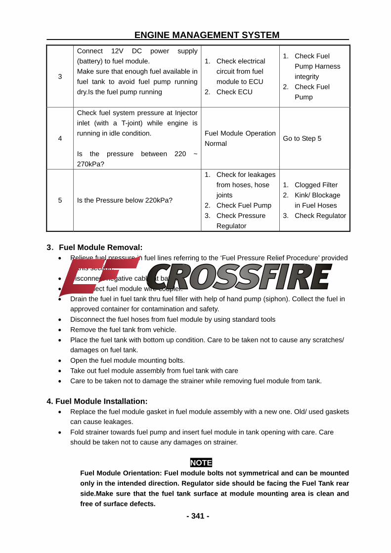
3
Connect 12V DC power supply
(battery) to fuel module.
Make sure that enough fuel available in
fuel tank to avoid fuel pump running
dry.Is the fuel pump running
1. Check electrical
circuit from fuel
module to ECU
2. Check ECU
1. Check Fuel
Pump Harness
integrity
2. Check Fuel
Pump
4
Check fuel system pressure at Injector
inlet (with a T-joint) while engine is
running in idle condition.
Is the pressure between 220 ~
270kPa?
Fuel Module Operation
Normal Go to Step 5
5 Is the Pressure below 220kPa?
1. Check for leakages
from hoses, hose
joints
2. Check Fuel Pump
3. Check Pressure
Regulator
1. Clogged Filter
2. Kink/ Blockage
in Fuel Hoses
3. Check Regulator
3.Fuel Module Removal: Relieve fuel pressure in fuel lines referring to the ‘Fuel Pressure Relief Procedure’ provided
in this section.
Disconnect negative cable at battery.
Disconnect fuel module wire coupler.
Drain the fuel in fuel tank thru fuel filler with help of hand pump (siphon). Collect the fuel in
approved container for contamination and safety.
Disconnect the fuel hoses from fuel module by using standard tools
Remove the fuel tank from vehicle.
Place the fuel tank with bottom up condition. Care to be taken not to cause any scratches/
damages on fuel tank.
Open the fuel module mounting bolts.
Take out fuel module assembly from fuel tank with care
Care to be taken not to damage the strainer while removing fuel module from tank.
4. Fuel Module Installation:
Replace the fuel module gasket in fuel module assembly with a new one. Old/ used gaskets
can cause leakages.
Fold strainer towards fuel pump and insert fuel module in tank opening with care. Care
should be taken not to cause any damages on strainer.
NOTE
Fuel Module Orientation: Fuel module bolts not symmetrical and can be mounted only in the intended direction. Regulator side should be facing the Fuel Tank rear side.Make sure that the fuel tank surface at module mounting area is clean and free of surface defects.
ENGINE MANAGEMENT SYSTEM
- 342 -
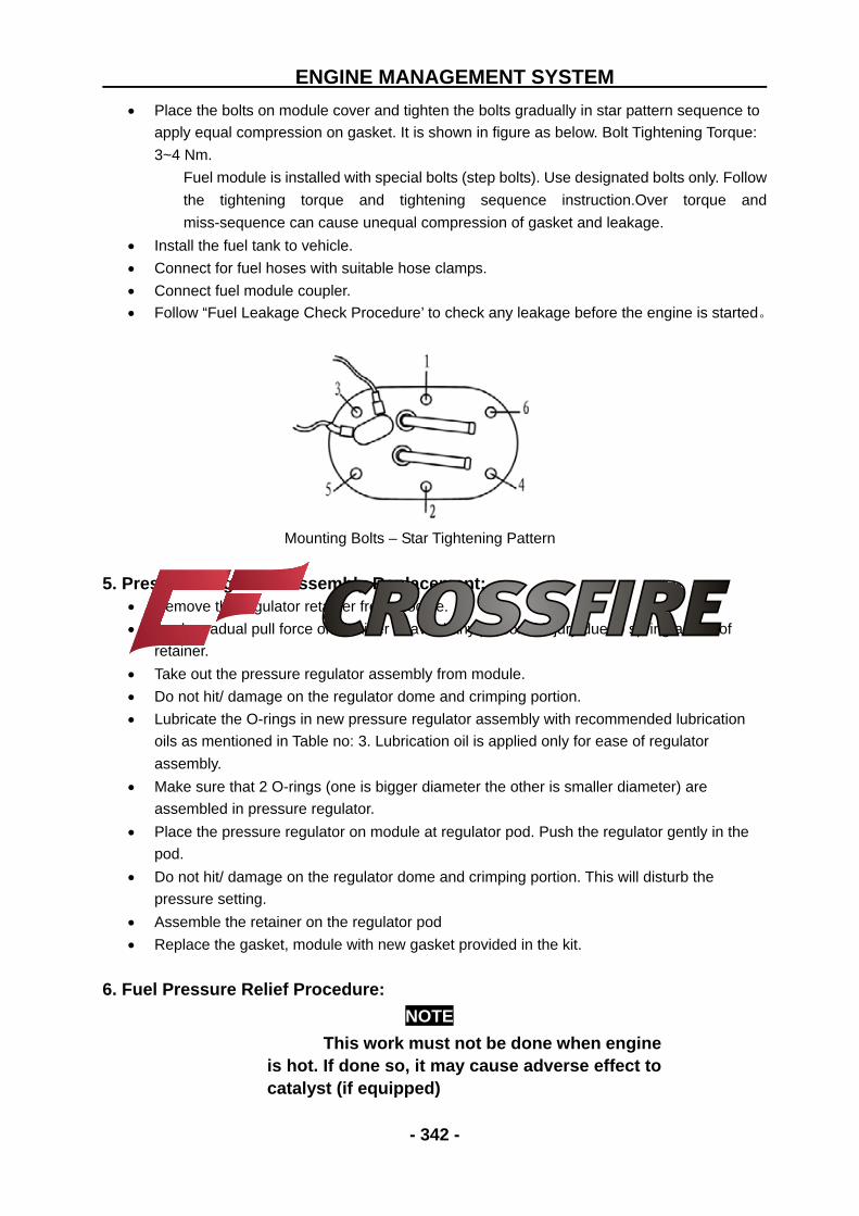
Place the bolts on module cover and tighten the bolts gradually in star pattern sequence to
apply equal compression on gasket. It is shown in figure as below. Bolt Tightening Torque:
3~4 Nm.
Fuel module is installed with special bolts (step bolts). Use designated bolts only. Follow
the tightening torque and tightening sequence instruction.Over torque and
miss-sequence can cause unequal compression of gasket and leakage.
Install the fuel tank to vehicle.
Connect for fuel hoses with suitable hose clamps.
Connect fuel module coupler.
Follow “Fuel Leakage Check Procedure’ to check any leakage before the engine is started。
Mounting Bolts – Star Tightening Pattern
5. Pressure Regulator Assembly Replacement:
Remove the regulator retainer from module.
Apply gradual pull force on retainer to avoid any personal injury due to spring action of
retainer.
Take out the pressure regulator assembly from module.
Do not hit/ damage on the regulator dome and crimping portion.
Lubricate the O-rings in new pressure regulator assembly with recommended lubrication
oils as mentioned in Table no: 3. Lubrication oil is applied only for ease of regulator
assembly.
Make sure that 2 O-rings (one is bigger diameter the other is smaller diameter) are
assembled in pressure regulator.
Place the pressure regulator on module at regulator pod. Push the regulator gently in the
pod.
Do not hit/ damage on the regulator dome and crimping portion. This will disturb the
pressure setting.
Assemble the retainer on the regulator pod
Replace the gasket, module with new gasket provided in the kit.
6. Fuel Pressure Relief Procedure:
NOTE
This work must not be done when engine is hot. If done so, it may cause adverse effect to catalyst (if equipped)
ENGINE MANAGEMENT SYSTEM
- 343 -
After making sure that engine is cold, relieve fuel pressure as follows. Place vehicle gear in ‘Neutral’.
Disconnect fuel module electrical coupler from vehicle harness.
Start engine and run till it stops due to lack of fuel. Repeat ignition key ON and OFF for 2 ~ 3
times of about 3 seconds each time to relieve fuel pressure in lines. Fuel Connections are
now safe for servicing.
Upon the completion of servicing, Connect Fuel Module Connector to Vehicle Harness.
7. Fuel Leakage Check Procedure:
After performing any service on fuel system, check to make sure that there are no fuel leakages
as below.
Fill about 3 ~ 5 liters of fuel in tank.
Turn Ignition key to ON position for 3 seconds (to operate fuel pump) and then turn to OFF
position. Repeat this for 3 ~ 4 times to apply fuel pressure in fuel lines.
In this state, check to see that there are no fuel leakage from any part of fuel system (Fuel
Tank, Hoses, Hose Joints, etc)
8. Handling – DOs and DONTs: FUEL MODULE HANDLING
ACTION REASON DO NOT: Drop Fuel Module on Floor Could cause internal damage to Fuel
Pump.
DO NOT: Run Fuel Pump Dry (without fuel
at pump inlet/ strainer) ensure atleast 3
litres of gasoline is present in the fuel tank
Caused internal damage to Fuel Pump
DO NOT: Damage the strainer during
servicing, insertion of fuel module in fuel
tank
Contamination enters fuel pump thru
damaged strainer damages the Fuel
Pump
DO NOT: Disassemble Fuel Pump and
regulator internal parts out side Delphi
premises.
DO NOT: Do any adjustments on pressure
regulator and pump except for
replacement.
Warranty void.
DO NOT: Use module harness for hold/
carry fuel module.
DO NOT: Pull Wiring Harness in vertical
direction to module cover
Wiring Harness Breakage/ Fuel Pump
Power disconnection
DO NOT: Use damaged/ distorted hose
clamps.
Can cause fuel seepage/ leakage.
ENGINE MANAGEMENT SYSTEM
- 344 -
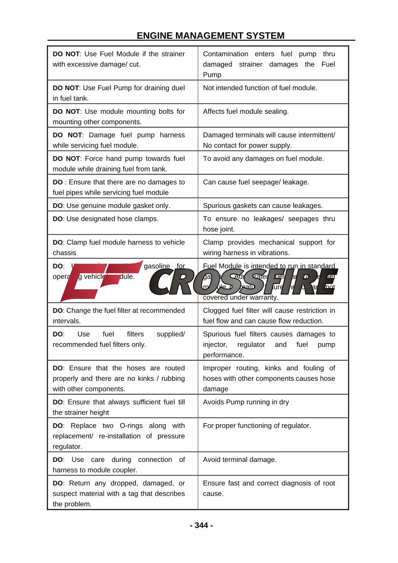
DO NOT: Use Fuel Module if the strainer
with excessive damage/ cut.
Contamination enters fuel pump thru
damaged strainer damages the Fuel
Pump
DO NOT: Use Fuel Pump for draining duel
in fuel tank.
Not intended function of fuel module.
DO NOT: Use module mounting bolts for
mounting other components.
Affects fuel module sealing.
DO NOT: Damage fuel pump harness
while servicing fuel module.
Damaged terminals will cause intermittent/
No contact for power supply.
DO NOT: Force hand pump towards fuel
module while draining fuel from tank.
To avoid any damages on fuel module.
DO : Ensure that there are no damages to
fuel pipes while servicing fuel module
Can cause fuel seepage/ leakage.
DO: Use genuine module gasket only. Spurious gaskets can cause leakages.
DO: Use designated hose clamps. To ensure no leakages/ seepages thru
hose joint.
DO: Clamp fuel module harness to vehicle
chassis
Clamp provides mechanical support for
wiring harness in vibrations.
DO: Use only standard gasoline for
operating vehicle/ module.
Fuel Module is intended to run in standard
gasoline. Adulterated fuel can cause fuel
module premature failures which are not
covered under warranty.
DO: Change the fuel filter at recommended
intervals.
Clogged fuel filter will cause restriction in
fuel flow and can cause flow reduction.
DO: Use fuel filters supplied/
recommended fuel filters only.
Spurious fuel filters causes damages to
injector, regulator and fuel pump
performance.
DO: Ensure that the hoses are routed
properly and there are no kinks / rubbing
with other components.
Improper routing, kinks and fouling of
hoses with other components causes hose
damage
DO: Ensure that always sufficient fuel till
the strainer height
Avoids Pump running in dry
DO: Replace two O-rings along with
replacement/ re-installation of pressure
regulator.
For proper functioning of regulator.
DO: Use care during connection of
harness to module coupler.
Avoid terminal damage.
DO: Return any dropped, damaged, or
suspect material with a tag that describes
the problem.
Ensure fast and correct diagnosis of root
cause.
ENGINE MANAGEMENT SYSTEM
- 345 -
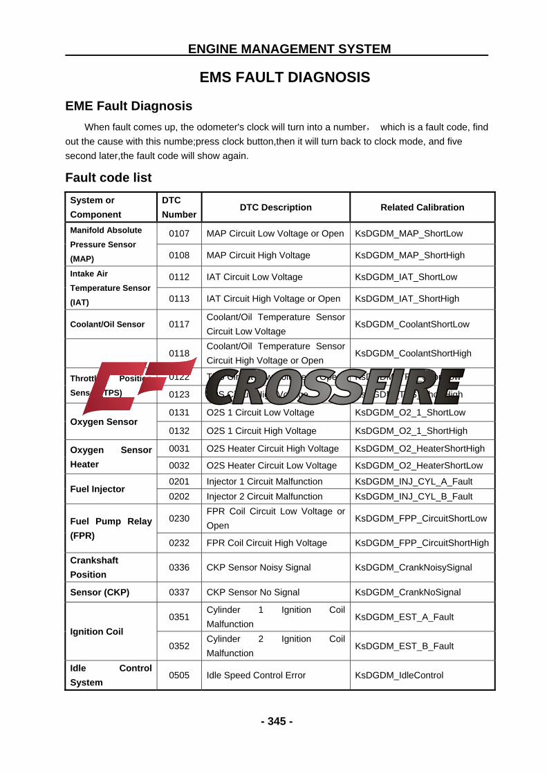
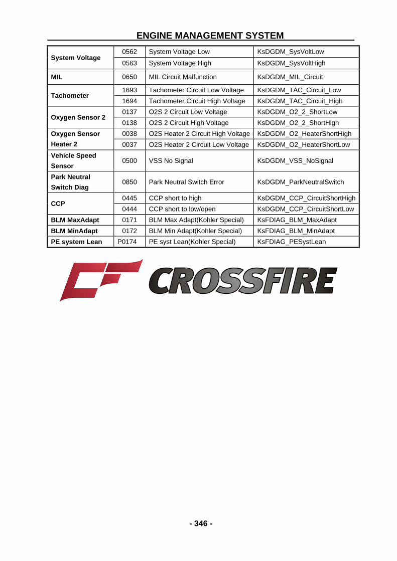
EMS FAULT DIAGNOSIS
EME Fault Diagnosis
When fault comes up, the odometer's clock will turn into a number, which is a fault code, find
out the cause with this numbe;press clock button,then it will turn back to clock mode, and five
second later,the fault code will show again.
Fault code list
System or
Component DTC
Number DTC Description Related Calibration
Manifold Absolute
Pressure Sensor
(MAP)
0107 MAP Circuit Low Voltage or Open KsDGDM_MAP_ShortLow
0108 MAP Circuit High Voltage KsDGDM_MAP_ShortHigh Intake Air
Temperature Sensor
(IAT)
0112 IAT Circuit Low Voltage KsDGDM_IAT_ShortLow
0113 IAT Circuit High Voltage or Open KsDGDM_IAT_ShortHigh
Coolant/Oil Sensor 0117 Coolant/Oil Temperature Sensor
Circuit Low Voltage KsDGDM_CoolantShortLow
0118 Coolant/Oil Temperature Sensor
Circuit High Voltage or Open KsDGDM_CoolantShortHigh
Throttle Position
Sensor (TPS) 0122 TPS Circuit Low Voltage or Open KsDGDM_TPS_ShortLow
0123 TPS Circuit High Voltage KsDGDM_TPS_ShortHigh
Oxygen Sensor 0131 O2S 1 Circuit Low Voltage KsDGDM_O2_1_ShortLow 0132 O2S 1 Circuit High Voltage KsDGDM_O2_1_ShortHigh
Oxygen Sensor
Heater 0031 O2S Heater Circuit High Voltage KsDGDM_O2_HeaterShortHigh
0032 O2S Heater Circuit Low Voltage KsDGDM_O2_HeaterShortLow