اﻟﻜﮭﺮﺑﺎﺋﯿﺔ اﻵﻻت ﻣﻌﻤﻞELECTRICAL MACHINES LAB. اﻟ ھﻜﮫ: ﻤﻘﺮر321 - ھﻨﺪﺳﺔ ﻛﮭﺮﺑﺎﺋ ﯿﺔEngE321-Electrical Engineering -SINGLE PHASE TRANSFORMER ; -THREE-PHASE TRANSFORMER ; -DC MACHENERY FUNDAMENTAL (Lucas Nulle Equipments) ; - DC GENERATOR ; - DC MOTOR. 1 Introduction One of the essential advantages of alternating current, including three-phase current, over direct ﺟﺎﻣﻌﺔ ﺟﺎزان اﻟﮭﻨﺪﺳﺔ ﻛﻠــﯿﺔ اﻟﻜﮭﺮﺑﺎﺋﯿﺔ اﻟﮭﻨﺪﺳﺔ ﻗﺴــﻢJazan University Engineering College Electrical Engineering Department
Transcript
معمل اآلالت الكھربائیةELECTRICAL MACHINES LAB.
یة كھربائھندسة - 321مقرر : ھكھ ال
EngE321-Electrical Engineering
-SINGLE PHASE TRANSFORMER ; -THREE-PHASE TRANSFORMER ; -DC MACHENERY FUNDAMENTAL (Lucas Nulle Equipments) ; - DC GENERATOR ; - DC MOTOR. 1 Introduction One of the essential advantages of alternating current, including three-phase current, over direct
جازان جامعة كلــیة الھندسة
قســم الھندسة الكھربائیة
Jazan University
Engineering College Electrical Engineering Department
current lies therein that this form of electrical energy can be economically produced in large power plants then transmitted over long distances at high voltages with relatively low losses and finally converted to a user-acceptable voltage level for the consumer. This is all made possible by transformers. Transformers of all kinds that are built to handle power from less than a Watt to over a gigawatt. Three-phase transformers are used exclusively for large power requirements while smaller power requirements are often adequately served by single-phase designs. Single-phase transformers will be examined first to illustrate just how transformers work. The law of induction is fundamental to the way that a transformer works. This law states that a voltage will be induced in a coil that is exposed to a periodically changing magnetic field. Since a transformer is generally employed to connect two differing voltage levels, it is necessary to have both sides uniquely designated with indexes. Typically the side intended as the input is designated the primary side and labeled with the index 1. The side of the transformer to which the load is connected is designated the secondary side and labeled with the index 2. According to the law of induction, if the number of turns in the windings are represented by N1 and N2 then the relationship between respective voltages for an ideal transformer will be:
V1 = N1
V2 N2
The voltage conversion ratio is the most important rating for a transformer. If one disregards transformer losses, then the apparent power must be the same on both sides. This can be used to derive a ratio for the currents as follows:
I1 = N2
I2 N1
The higher transmission voltage is made, the smaller the current will be for the same amount of conducted power. This allows high-voltage lines to be utilized that have a smaller conductor cross section which, in turn, is more economical. In addition to a transformer's transformation ratio there are other factors which also determine the operational behavior of a transformer. These are nominal apparent power, no-load current, short- circuit voltage, and efficiency. The experiments to be performed here will use one transformer with a laminated core and another transformer which has a toroidal core, each of these will have two secondary windings. The operational behavior for both types will be similar; differences arise only in their short-circuit voltages and no-load current. Furthermore, a distinction must be made between the physical structure differences for "isolating transformers" and "autotransformers". Isolating transformers have absolutely no galvanic coupling between its windings whereas the autotransformer is formed by two, series-connected, parts of a single winding. One portion of the winding, referred to as the common winding, is common to both sides. The other portion of the winding, referred to as the auxiliary winding or series winding, together with the common winding forms the high voltage side. Voltages can be transformed up or down with an autotransformer. Its overall potential power output is referred to as its throughput rating. Its transfer from input to output winding is in part galvanic and part inductive. The greater the galvanic portion contributes to the amount of power transferred, the smaller the inductive portion will be. It is this inductive portion, also referred to as "nominal power" that determines the physical size of the transformer. This means that the savings of copper and iron, in comparison to a transformer with separate windings, becomes larger as the difference between input and output voltages becomes smaller. The experiments to be performed here will use an autotransformer that has multiple taps.
The distribution grid for electrical power primarily uses three-phase transformers. Like single-phase transformers, these three-phase versions can also be wound as isolating transformers or as autotransformers. Even designs with three windings per phase are commonplace. Such transformers allow, for example, one generator to simultaneously feed two different voltage levels of a power grid. A three-phase transformer can be envisioned as the interconnection of three single-phase transformers. Though this allows various circuit configurations for primary and secondary sides to be realized, one of these configurations will result in the optimal solution for the given application. For the star circuit, a voltage applied to a single winding is
V ' = VN , N 3 whereas for the delta circuit it is VN that is the nominal voltage. This means that the star circuit's overhead for isolation is less, but does require conductors with larger cross-sections due to the higher currents to be handled. Another configuration, primarily used for the low voltage side of local transformers, is the zigzag circuit (a.k.a. interconnected star connection). It is formed by the series connection of two different phases of the secondary windings. Connection symbols are used for identify different circuit configurations. The letter "D" or "d" is used to identify a delta circuit, "Y" or "y" for a star circuit and "z" for a zigzag circuit. The capital letter is used for the primary side and the lowercase letter for the secondary side. These letter codes are followed by a code number that describes the lagging of phase-to-phase voltage on the low-voltage side opposite the high-voltage side in multiples of 30° (comparable to the numbers on the face of a clock). If the neutral point of a star or zigzag configured winding is brought out, then this is identified by the letter "N" or "n" (depending on transformer side). The most common circuit configurations are Yy0, Dy5, Yd5 and Yz5. Single-phase loads can only be connected to the transformer when the neutral point is brought out. The individual phase leg windings are differentiated with the letters "U", "V", and "W". A code number preceding these letters designates the winding's number (1: primary winding, 2 and, when present, 3: for secondary windings). A further code number after the letter establishes the begin (1) and end (2) of the winding. Whereas a transformer's connection symbol is virtually meaningless in symmetrical configurations, they are decisive for behavior where asymmetrical loads and faults are concerned. The three-phase transformer used in these experiments possesses three separate windings per phase that can be interconnected freely. Behavior will be investigated for both symmetric as well as asymmetric load conditions. The so-called "Scott transformer" represents a special variation of the three-phase transformer. It permits the creation of a special circuit for producing two alternating voltages from a single three phase system. The two AC voltages represent independent systems which exhibit a 90° phase shift between them. Experiments will also be conducted with this type of transformer.
2 Safety Precautions and Measurement Notifications 2.1 Safety Precautions Voltage-free metal components (e.g. housings) are to be connected with a PE ground conductor according to VDE regulations (Verband Deutscher Elektrotechniker, which translates to Associa- tion of German Electro-technical Engineers). Power supply voltage is to be turned off when making any change to the experimental setup.
2.2 Measurement Notifications The power supply voltage to single-phase transformers under investigation is to be connected via an isolating variable transformer (726 85) that provides an AC voltage in the range of 0 ... 260 V. For three-phase transformers, power supply voltage is to be provided via the three-phase variable transformer (725 442 D) that has a voltage range of 0 ... 400 V. Voltage and current measurements are to be made with RMS meters (727 10). Simple voltmeters and ammeters can also be used as an alternative. Notices about the proper measurement ranges are included in equipment lists for individual experiments. A measurement instrument capable of providing results within a tolerance range of 0.05% of measured value (or better) is recommended for investigations of voltage behavior in conjunction with resistive, capacitive and inductive loads. The unit configuration diagrams always show the RMS meter devices. An oscilloscope (e.g. 575 211) is required in order to visualize the characteristic phase shifts that take place between the high and low voltage sides of the three-phase transformer. This is to be connected to the test object via an isolation amplifier (735 261). The details of utilizing the isolation amplifier and the oscilloscope are to be taken from their respective operating instructions.
It is recommended that transformers to be investigated are first loaded with nominal current for a few minutes before making measurements. This is done to ensure that they have reached their operating temperature so that reproducible results are achieved. On the other hand, one should be careful not to place other devices (e.g. measuring instruments) directly above the test object or resistive loads. This is because of the heat dissipated by these test objects and resistive loads.
Equipment List: 1 single-phase transformer
1 variable transformer 0 ... 260 V / 4 A 1 resistive load 1 inductive load 1 capacitive load 1 set of 10 safety connectors, black 1 set of 10 safety connectors, green/yellow 1 set of 32 safety experiment cables 1 set of 10 safety experiment cables, green/yellow 1 power factor meter 3 RMS meters as an alternative to the RMS meters: 2 voltmeters 0 ... 400 V 1 ammeter 0 ... 1 A 1 ammeter 0 ... 2.5 A
Experiments with the Single-phase Transformer
1. Study Goals: After carrying out the experiments, the student will be capable of: � connecting a single-phase transformer and then demonstrating the significance of the terms
"voltage transformation", "current transformation" and "no-load current" with appropriate experimental circuits.
� setting up a measurement circuit for determining short-circuit voltage and sustained short- circuit current and then be able to measure these values.
� investigating a transformer's voltage behavior when it is connected to a resistive load and determining its efficiency as a function of the load.
� investigating and interpreting a transformer's voltage behavior when it is connected to an inductive or capacitive load.
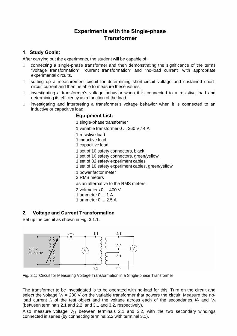
2. Voltage and Current Transformation Set up the circuit as shown in Fig. 3.1.1.
Fig. 2.1: Circuit for Measuring Voltage Transformation in a Single-phase Transformer
The transformer to be investigated is to be operated with no-load for this. Turn on the circuit and select the voltage V1 = 230 V on the variable transformer that powers the circuit. Measure the no- load current I0 of the test object and the voltage across each of the secondaries V2 and V3 (between terminals 2.1 and 2.2, and 3.1 and 3.2, respectively). Also measure voltage V23 between terminals 2.1 and 3.2, with the two secondary windings connected in series (by connecting terminal 2.2 with terminal 3.1).
Reference the voltages V1, V2 and V3 to the turn counts N1, N2 and N3 of their respective windings.
Formulate an equation for voltage transformation ratio from the above data.
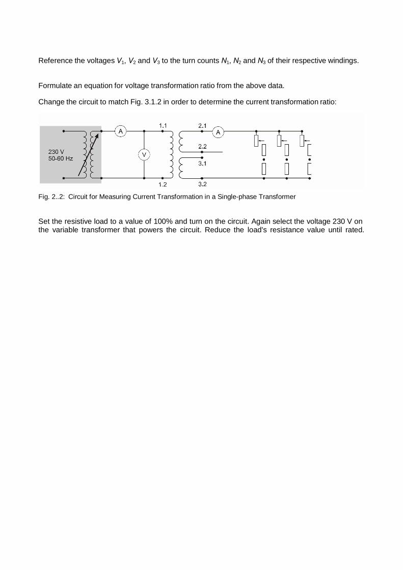
Change the circuit to match Fig. 3.1.2 in order to determine the current transformation ratio:
Fig. 2..2: Circuit for Measuring Current Transformation in a Single-phase Transformer
Set the resistive load to a value of 100% and turn on the circuit. Again select the voltage 230 V on the variable transformer that powers the circuit. Reduce the load's resistance value until rated.
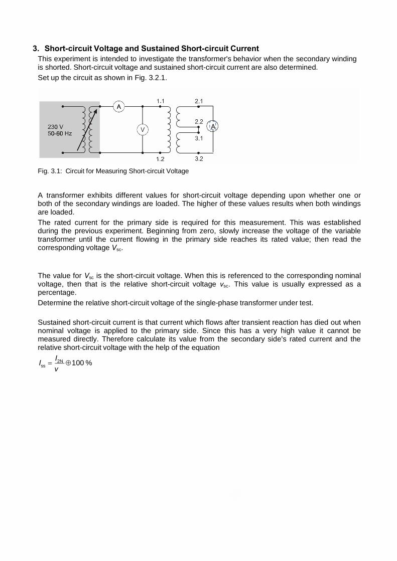
3. Short-circuit Voltage and Sustained Short-circuit Current This experiment is intended to investigate the transformer's behavior when the secondary winding is shorted. Short-circuit voltage and sustained short-circuit current are also determined. Set up the circuit as shown in Fig. 3.2.1.
Fig. 3.1: Circuit for Measuring Short-circuit Voltage
A transformer exhibits different values for short-circuit voltage depending upon whether one or both of the secondary windings are loaded. The higher of these values results when both windings are loaded. The rated current for the primary side is required for this measurement. This was established during the previous experiment. Beginning from zero, slowly increase the voltage of the variable transformer until the current flowing in the primary side reaches its rated value; then read the corresponding voltage Vsc.
The value for Vsc is the short-circuit voltage. When this is referenced to the corresponding nominal voltage, then that is the relative short-circuit voltage vsc. This value is usually expressed as a percentage. Determine the relative short-circuit voltage of the single-phase transformer under test.
Sustained short-circuit current is that current which flows after transient reaction has died out when nominal voltage is applied to the primary side. Since this has a very high value it cannot be measured directly. Therefore calculate its value from the secondary side's rated current and the relative short-circuit voltage with the help of the equation
Iss = I2N ⊕ 100 %
v
A
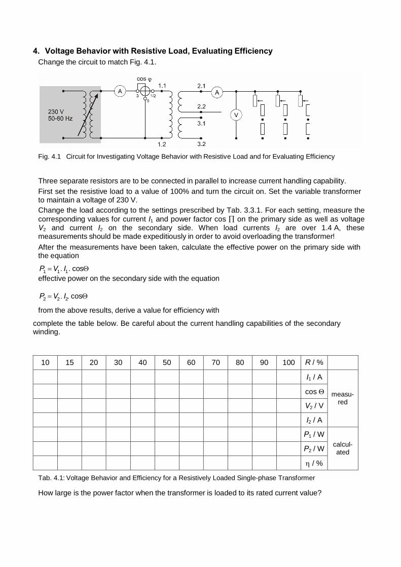
4. Voltage Behavior with Resistive Load, Evaluating Efficiency Change the circuit to match Fig. 4.1.
Fig. 4.1 Circuit for Investigating Voltage Behavior with Resistive Load and for Evaluating Efficiency
Three separate resistors are to be connected in parallel to increase current handling capability. First set the resistive load to a value of 100% and turn the circuit on. Set the variable transformer to maintain a voltage of 230 V. Change the load according to the settings prescribed by Tab. 3.3.1. For each setting, measure the corresponding values for current I1 and power factor cos ∏ on the primary side as well as voltage V2 and current I2 on the secondary side. When load currents I2 are over 1.4 A, these measurements should be made expeditiously in order to avoid overloading the transformer! After the measurements have been taken, calculate the effective power on the primary side with the equation
P1 = V1 . I1 . cosΘ effective power on the secondary side with the equation P2 = V2 . I2. cosΘ
from the above results, derive a value for efficiency with
complete the table below. Be careful about the current handling capabilities of the secondary winding.
R / % 100 90 80 70 60 50 40 30 20 15 10 measu-
red
I1 / A
cos Θ
V2 / V
I2 / A
calcul- ated
P1 / W
P2 / W
η / %
Tab. 4.1: Voltage Behavior and Efficiency for a Resistively Loaded Single-phase Transformer
How large is the power factor when the transformer is loaded to its rated current value?
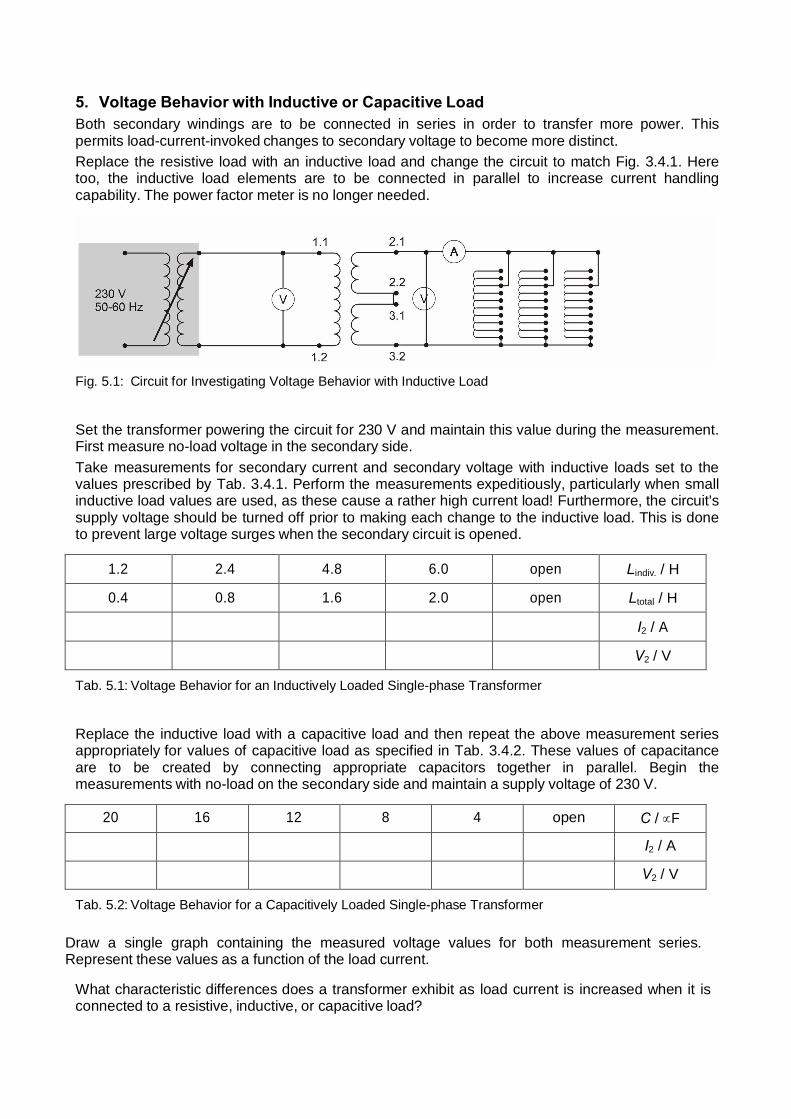
5. Voltage Behavior with Inductive or Capacitive Load Both secondary windings are to be connected in series in order to transfer more power. This permits load-current-invoked changes to secondary voltage to become more distinct. Replace the resistive load with an inductive load and change the circuit to match Fig. 3.4.1. Here too, the inductive load elements are to be connected in parallel to increase current handling capability. The power factor meter is no longer needed.
Fig. 5.1: Circuit for Investigating Voltage Behavior with Inductive Load
Set the transformer powering the circuit for 230 V and maintain this value during the measurement. First measure no-load voltage in the secondary side. Take measurements for secondary current and secondary voltage with inductive loads set to the values prescribed by Tab. 3.4.1. Perform the measurements expeditiously, particularly when small inductive load values are used, as these cause a rather high current load! Furthermore, the circuit's supply voltage should be turned off prior to making each change to the inductive load. This is done to prevent large voltage surges when the secondary circuit is opened.
Lindiv. / H open 6.0 4.8 2.4 1.2
Ltotal / H open 2.0 1.6 0.8 0.4
I2 / A
V2 / V
Tab. 5.1: Voltage Behavior for an Inductively Loaded Single-phase Transformer
Replace the inductive load with a capacitive load and then repeat the above measurement series appropriately for values of capacitive load as specified in Tab. 3.4.2. These values of capacitance are to be created by connecting appropriate capacitors together in parallel. Begin the measurements with no-load on the secondary side and maintain a supply voltage of 230 V.
C / ∝F open 4 8 12 16 20
I2 / A
V2 / V
Tab. 5.2: Voltage Behavior for a Capacitively Loaded Single-phase Transformer Draw a single graph containing the measured voltage values for both measurement series. Represent these values as a function of the load current.
What characteristic differences does a transformer exhibit as load current is increased when it is connected to a resistive, inductive, or capacitive load?
Experiments with the Three-phase Transformer
1. Study Goals: After carrying out the experiments, the student will be capable of: � connecting a three-phase transformer in various types of circuits (connection symbols) and
then determining their respective values for voltage transformation, current transformation and no-load current.
� investigating the behavior of the transformer when connected in various connection symbols to balanced and unbalanced loads.
� proving phase rotation between upper and lower voltage sides for individual connection symbols on the basis of appropriate test circuits.
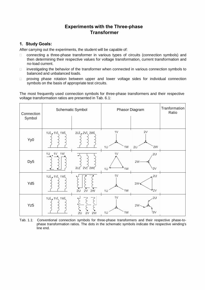
The most frequently used connection symbols for three-phase transformers and their respective voltage transformation ratios are presented in Tab. 6.1:
Connection Symbol
Schematic Symbol Phasor Diagram Tranformation Ratio
Yy0
Dy5
Yd5
Yz5
Tab. 1.1: Conventional connection symbols for three-phase transformers and their respective phase-to- phase transformation ratios. The dots in the schematic symbols indicate the respective winding's line end.
1
Equipment List: 1 three-phase transformer 1 3-phase voltage 400/2.5 A
1 softcase 42PU 400 V 1 resistive load 1 set of 10 safety connectors, black 1 set of 10 safety connectors, green/yellow 1 set of 32 safety experiment cables 1 set of 10 safety experiment cables, green/yellow 1 dual channel oscilloscope 303 1 four channel isolation amplifier 3 RMS meters as an alternative to the RMS meters: 2 voltmeters 0 ... 400 V 2 ammeters 0 ... 1 A
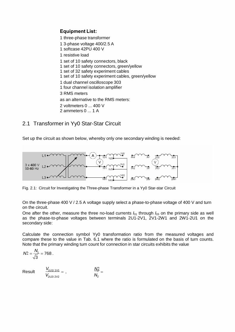
2.1 Transformer in Yy0 Star-Star Circuit
Set up the circuit as shown below, whereby only one secondary winding is needed:
Fig. 2.1: Circuit for Investigating the Three-phase Transformer in a Yy0 Star-star Circuit
On the three-phase 400 V / 2.5 A voltage supply select a phase-to-phase voltage of 400 V and turn on the circuit. One after the other, measure the three no-load currents I01 through I03 on the primary side as well as the phase-to-phase voltages between terminals 2U1-2V1, 2V1-2W1 and 2W1-2U1 on the secondary side:
Calculate the connection symbol Yy0 transformation ratio from the measured voltages and compare these to the value in Tab. 6.1 where the ratio is formulated on the basis of turn counts. Note that the primary winding turn count for connection in star circuits exhibits the value
N2 = N1 = 768 . 3
Result V1U1–1V1 = , N12
= V2U2–2V2 N2
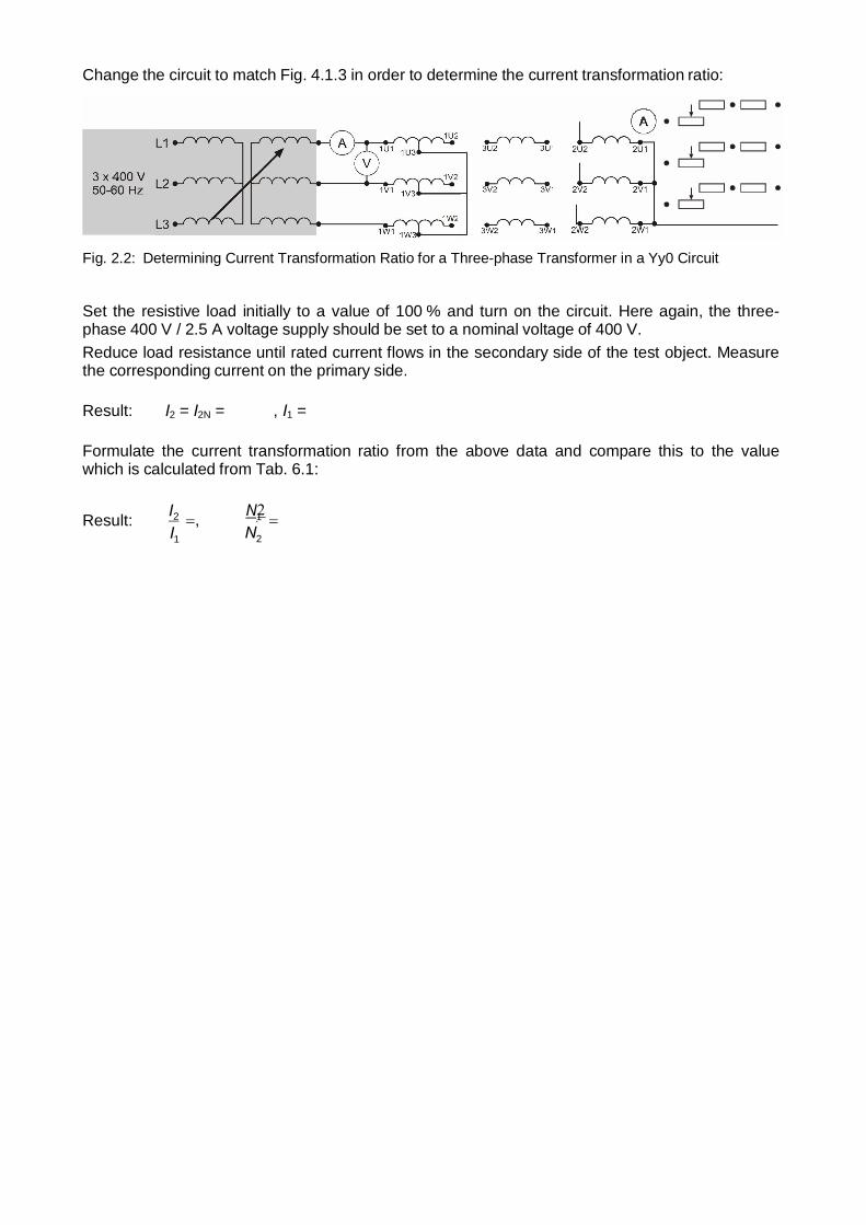
Change the circuit to match Fig. 4.1.3 in order to determine the current transformation ratio:
Fig. 2.2: Determining Current Transformation Ratio for a Three-phase Transformer in a Yy0 Circuit
Set the resistive load initially to a value of 100 % and turn on the circuit. Here again, the three- phase 400 V / 2.5 A voltage supply should be set to a nominal voltage of 400 V. Reduce load resistance until rated current flows in the secondary side of the test object. Measure the corresponding current on the primary side.
Result: I2 = I2N = , I1 =
Formulate the current transformation ratio from the above data and compare this to the value which is calculated from Tab. 6.1:
Result: I2 =, I1
N12 N2
=
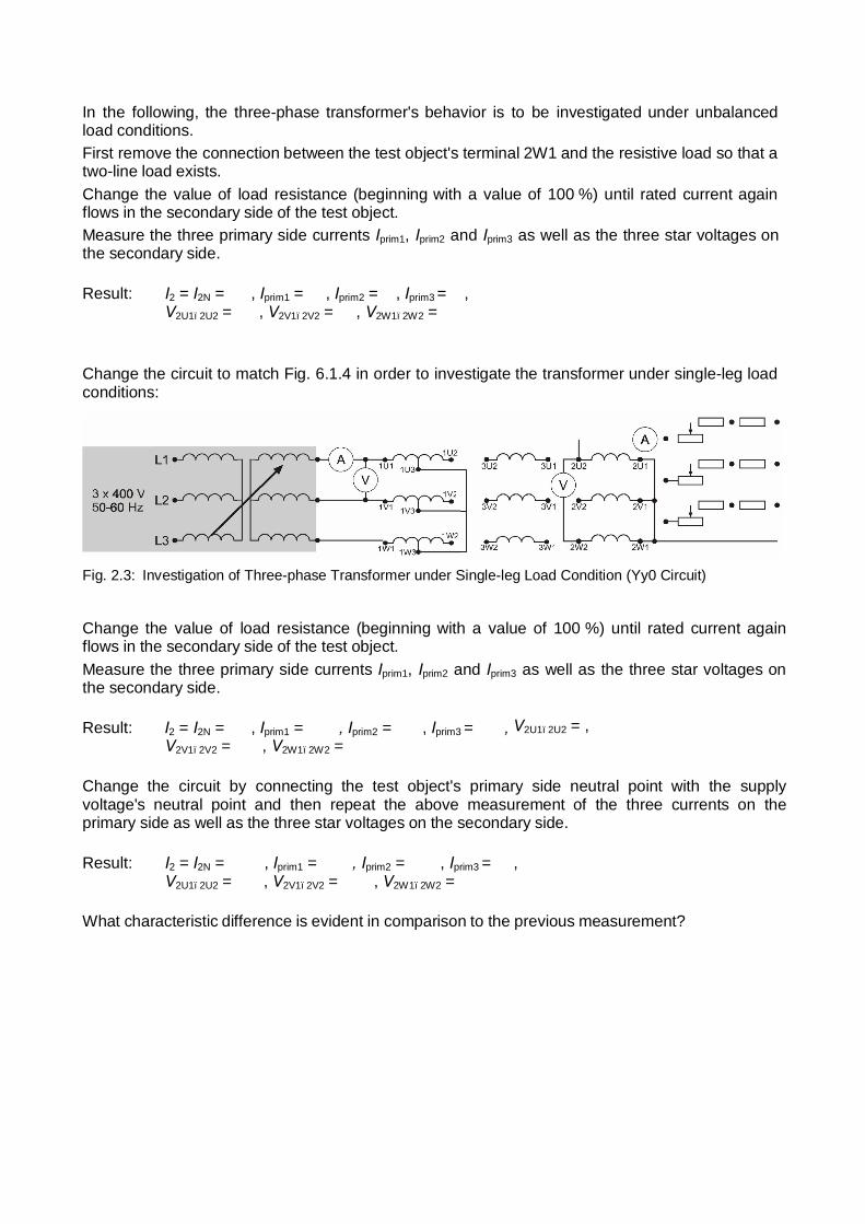
In the following, the three-phase transformer's behavior is to be investigated under unbalanced load conditions. First remove the connection between the test object's terminal 2W1 and the resistive load so that a two-line load exists. Change the value of load resistance (beginning with a value of 100 %) until rated current again flows in the secondary side of the test object. Measure the three primary side currents Iprim1, Iprim2 and Iprim3 as well as the three star voltages on the secondary side.
Change the circuit to match Fig. 6.1.4 in order to investigate the transformer under single-leg load conditions:
Fig. 2.3: Investigation of Three-phase Transformer under Single-leg Load Condition (Yy0 Circuit)
Change the value of load resistance (beginning with a value of 100 %) until rated current again flows in the secondary side of the test object. Measure the three primary side currents Iprim1, Iprim2 and Iprim3 as well as the three star voltages on the secondary side.
Change the circuit by connecting the test object's primary side neutral point with the supply voltage's neutral point and then repeat the above measurement of the three currents on the primary side as well as the three star voltages on the secondary side.
What characteristic difference is evident in comparison to the previous measurement?
1
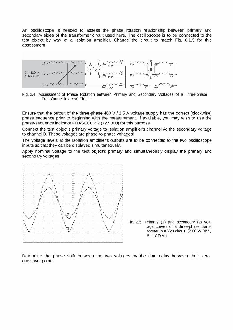
An oscilloscope is needed to assess the phase rotation relationship between primary and secondary sides of the transformer circuit used here. The oscilloscope is to be connected to the test object by way of a isolation amplifier. Change the circuit to match Fig. 6.1.5 for this assessment.
Fig. 2.4: Assessment of Phase Rotation between Primary and Secondary Voltages of a Three-phase Transformer in a Yy0 Circuit
Ensure that the output of the three-phase 400 V / 2.5 A voltage supply has the correct (clockwise) phase sequence prior to beginning with the measurement. If available, you may wish to use the phase-sequence indicator PHASECOP 2 (727 300) for this purpose. Connect the test object's primary voltage to isolation amplifier's channel A; the secondary voltage to channel B. These voltages are phase-to-phase voltages! The voltage levels at the isolation amplifier's outputs are to be connected to the two oscilloscope inputs so that they can be displayed simultaneously. Apply nominal voltage to the test object's primary and simultaneously display the primary and secondary voltages.
2
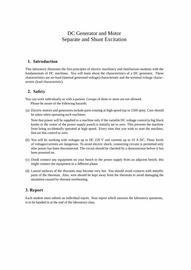
Fig. 2.5: Primary (1) and secondary (2) volt- age curves of a three-phase trans- former in a Yy0 circuit. (2.00 V/ DIV., 5 ms/ DIV.)
Determine the phase shift between the two voltages by the time delay between their zero crossover points.
Practice Questions
1) Why do both voltages of a single-phase transformer behave proportionally to their
respective turn counts while their current values are inversely proportional?
2) How is short-circuit voltage defined for a transformer?
3) What are the pros and cons of a large value for short-circuit voltage?
4) Why is short-circuit voltage typically expressed as a relative value (based on nominal voltage)?
5) What does the term "sustained short-circuit current" mean?
6) What are the essential differences between transformers with a conventional core
and those with a toroidal core? 7) What determines the efficiency of a transformer?
8) What limits the amount of power that can be transferred over a transformer?
9) What are the essential differences between autotransformers and transformers with
separate windings?
10) What is to be understood under the term "connector symbol" for a three-phase transformer?
11) What is the meaning of so-called "winding points" on a schematic diagram?
12) Why is it advantageous to connect the high voltage side's neutral point in a Yy0
circuit to the neutral line of the supply grid?
13) What are the advantages of the delta connection; what advantages does the star connection offer?
14) Where is the zigzag circuit used? 15) What must be observed when connecting two three-phase transformers in parallel?
16) How can the phase shift between upper and lower voltage sides be measured?
17) What is the so-called "Scott circuit" used for? 18) What is the so-called "V circuit" used for in three-phase systems?
DC Generator and Motor
Separate and Shunt Excitation
1. Introduction
This laboratory illustrates the first principles of electric machinery and familiarizes students with the fundamentals of DC machines. You will learn about the characteristics of a DC generator. These characteristics are no-load (internal generated voltage) characteristic and the terminal voltage charac- teristic (load characteristic).
2. Safety
You can work individually or with a partner. Groups of three or more are not allowed. Please be aware of the following hazards.
(a) Electric motors and generators include parts rotating at high speed (up to 1500 rpm). Care should
be taken when operating such machines. Note that power will be supplied to a machine only if the variable DC voltage control (a big black knobe in the center of the power supply panel) is initially set to zero. This prevents the machine from being accidentally operated at high speed. Every time that you wish to start the machine, first set this control to zero.
(b) You will be working with voltages up to DC 220 V and currents up to 10 A DC. These levels
of voltages/currents are dangerous. To avoid electric shock, connecting circuits is permitted only after power has been disconnected. The circuit should be checked by a demonstrator before it has been powered on.
(c) Don’t connect any equipment on your bench to the power supply from an adjacent bench; this
might connect the equipment to a different phase.
(d) Lateral surfaces of the rheostats may become very hot. You should avoid contacts with metallic parts of the rheostats. Also, wire should be kept away from the rheostats to avoid damaging the insulation caused by rheostat overheating.
3. Report
Each student must submit an individual report. Your report which answers the laboratory questions, is to be handed in at the end of the laboratory class.
4. Introduction
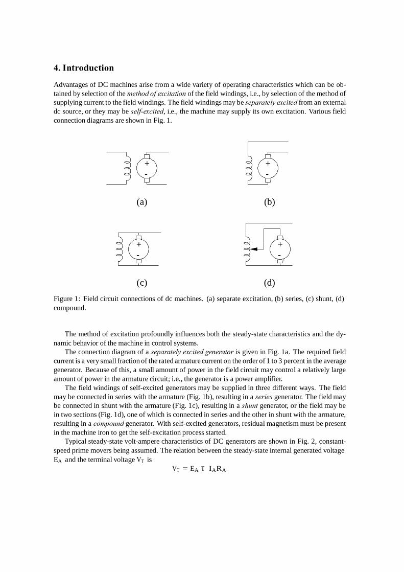
Advantages of DC machines arise from a wide variety of operating characteristics which can be ob- tained by selection of the method of excitation of the field windings, i.e., by selection of the method of supplying current to the field windings. The field windings may be separately excited from an external dc source, or they may be self-excited, i.e., the machine may supply its own excitation. Various field connection diagrams are shown in Fig. 1.
+ + - -
(a) (b)
+ + - -
(c) (d)
Figure 1: Field circuit connections of dc machines. (a) separate excitation, (b) series, (c) shunt, (d) compound.
The method of excitation profoundly influences both the steady-state characteristics and the dy- namic behavior of the machine in control systems.
The connection diagram of a separately excited generator is given in Fig. 1a. The required field current is a very small fraction of the rated armature current on the order of 1 to 3 percent in the average generator. Because of this, a small amount of power in the field circuit may control a relatively large amount of power in the armature circuit; i.e., the generator is a power amplifier.
The field windings of self-excited generators may be supplied in three different ways. The field may be connected in series with the armature (Fig. 1b), resulting in a series generator. The field may be connected in shunt with the armature (Fig. 1c), resulting in a shunt generator, or the field may be in two sections (Fig. 1d), one of which is connected in series and the other in shunt with the armature, resulting in a compound generator. With self-excited generators, residual magnetism must be present in the machine iron to get the self-excitation process started.
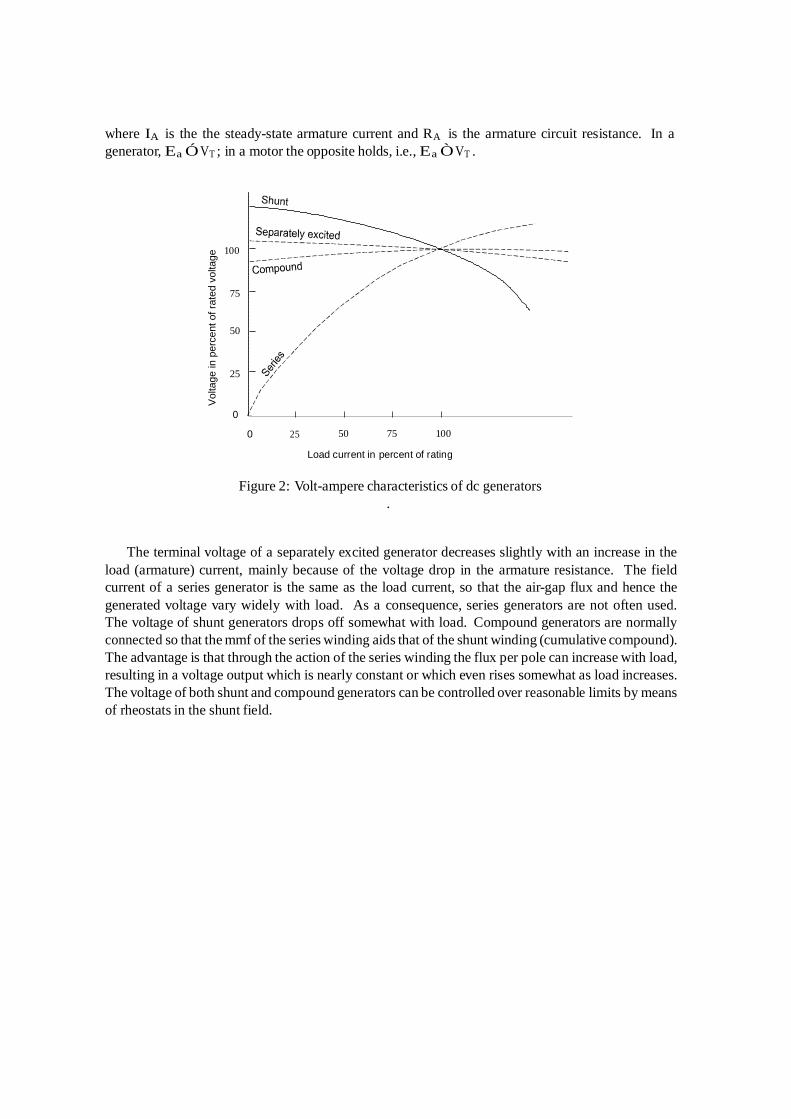
Typical steady-state volt-ampere characteristics of DC generators are shown in Fig. 2, constant- speed prime movers being assumed. The relation between the steady-state internal generated voltage EA and the terminal voltage VT is
VT = EA − IA RA
Vol
tage
in p
erce
nt o
f rat
ed v
olta
ge
where IA is the the steady-state armature current and RA is the armature circuit resistance. In a generator, Ea ≥ VT ; in a motor the opposite holds, i.e., Ea ≤ VT .
100
75
50
25
0
0 25
50 75
100
Load current in percent of rating
Figure 2: Volt-ampere characteristics of dc generators
.
The terminal voltage of a separately excited generator decreases slightly with an increase in the load (armature) current, mainly because of the voltage drop in the armature resistance. The field current of a series generator is the same as the load current, so that the air-gap flux and hence the generated voltage vary widely with load. As a consequence, series generators are not often used. The voltage of shunt generators drops off somewhat with load. Compound generators are normally connected so that the mmf of the series winding aids that of the shunt winding (cumulative compound). The advantage is that through the action of the series winding the flux per pole can increase with load, resulting in a voltage output which is nearly constant or which even rises somewhat as load increases. The voltage of both shunt and compound generators can be controlled over reasonable limits by means of rheostats in the shunt field.
5. Equipment
M = DC machine MV 1036 (electric torque meter), or DC machine MV 1034, or
DC machine MV 1028 (2.0 kW, 220 V, 1750 rpm) which will operate as a prime mover
G = DC machine MV 1006, (1.2 kW, 220 V, 1750 rpm) which will operate as a generator
T G = Tachometer generator MV 1024, 20.8 V (DVM reading) per 1000 rpm RM , RG = Shunt rheostats MV 1095 or MV 1905 RL = Load resistor MV 1100 IG, IM , IL = AVOs (ammeters) V = AVO (voltmeter) S = Switch F = Power supply MV 1300.
The two stations with torque meter MV 1036 have the rheostat RM and two ammeters available on the front panel. For the three other stations with the DC machine MV 1034 / MV 1028, an extra rheostat and two extra AVOs (avometers) are provided. Use them to connect the circuit of Figure 3. All five stations should use a DVM to measure the speed. The rpm meters available on the front panel of torque meters MV 1036 give inaccurate reading, don’t use them. A DVM is used only with the Tachometer generator; for other measurements use AVOs. AVOs should be switched to the ”OFF” position when you finish.
Take extreme care while working with AVOs. Negligent handling of the AVO can damage it; each AVO costs more than $1000, a repair costs another $800. When measuring DC voltage, make sure that the AVO is set to measure voltage and not current, and vice versa. Before the system is powered, make sure that you have chosen appropriate current/voltage range setting. I.e., if you expect that the current will be of 6 A then the AVO must be set for this current range. Disconnect power if you need to change any of the settings. Never change AVO’s settings while operating the circuit. Suggested initial settings are shown in circuit diagrams (next to the corresponding circuit element).
6. Ratings
Each electric machine is designed by a manufacturer to operate in a certain range of voltages and currents. The parameters quoted by the manufacturer are known as rating of the machine. Operating the machine at a voltage or current larger than the rated voltage and current for an extended period of time may damage the machine. Before you start connecting circuits write down the ratings of the machines shown on the rating plates. These ratings must not be exceeded at any time during the laboratory exercises.
7. Connecting up and starting
This experiment is to check that the machines work as expected.
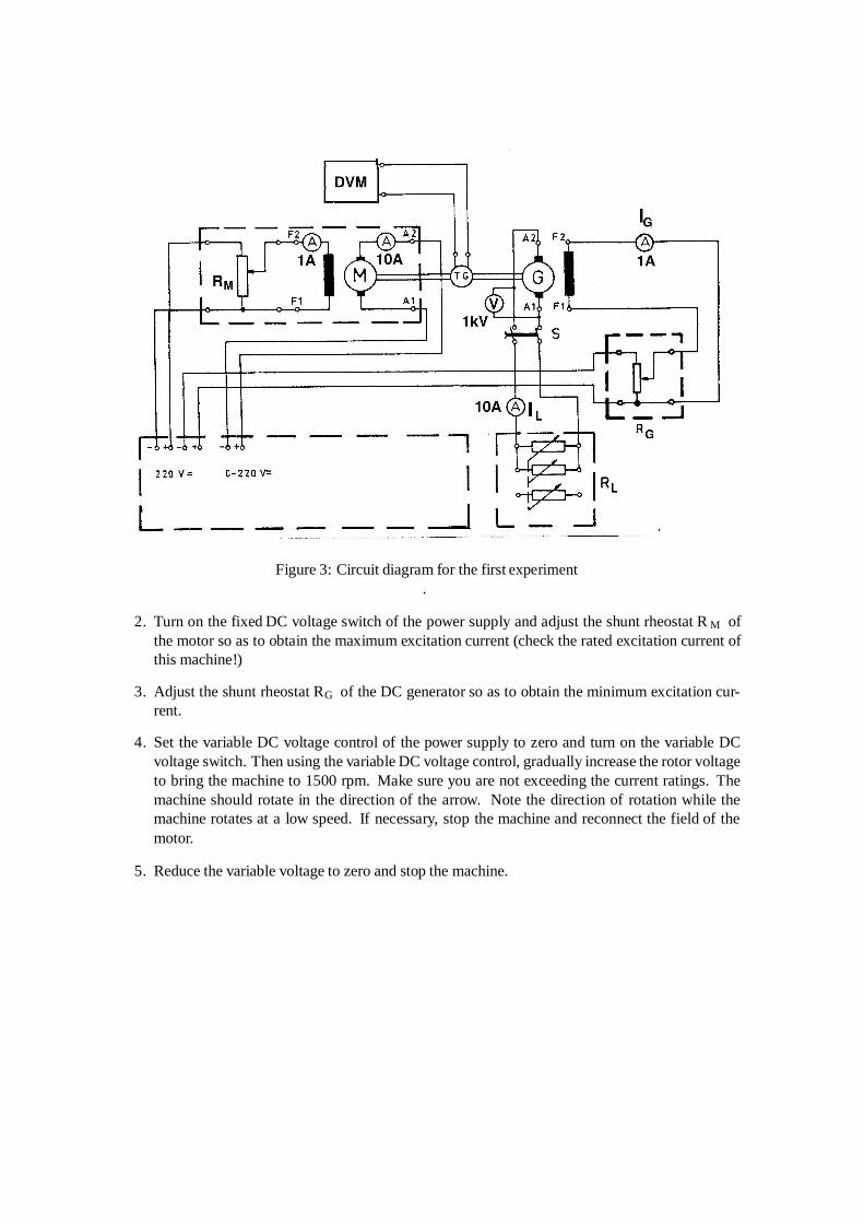
1. Connect the torque meter MV 1036 or DC machine MV 1034 as motor and the DC machine
MV 1006 as generator in accordance with the circuit diagram in Figure 3. The circuit should now be checked by the lab demonstrator.
Figure 3: Circuit diagram for the first experiment .
2. Turn on the fixed DC voltage switch of the power supply and adjust the shunt rheostat R M of
the motor so as to obtain the maximum excitation current (check the rated excitation current of this machine!)
3. Adjust the shunt rheostat RG of the DC generator so as to obtain the minimum excitation cur-
rent.
4. Set the variable DC voltage control of the power supply to zero and turn on the variable DC voltage switch. Then using the variable DC voltage control, gradually increase the rotor voltage to bring the machine to 1500 rpm. Make sure you are not exceeding the current ratings. The machine should rotate in the direction of the arrow. Note the direction of rotation while the machine rotates at a low speed. If necessary, stop the machine and reconnect the field of the motor.
5. Reduce the variable voltage to zero and stop the machine.
8 . Measurement of no-load characteristic EA=f (IG), i.e., the internal
generated voltage as function of the excitation current
1. Using the procedure described above, adjust the motor to bring the speed to 1750 rpm. This speed must be maintained constant throughout the experiment and must therefore be checked from time to time. The switch S must be off.
2. Vary the excitation current IF in steps of 0.1 A from zero to maximum and for every step make
a note of IG and the induced voltage read on the voltmeter V . Enter the values in a table.
3. Vary the excitation current in steps of 0.1 A from maximum to zero and for every step make a note of IG and V . Observe that, with the increase and decrease of the excitation current, the induced voltage will differ.
4. Stop the machine.
Repeat the above two measurements at a speed of 1500 rpm.
IF, mA EA , V IF , mA EA , V IF, mA EA , V IF, mA EA , V 9. Measurement of the terminal voltage (load) characteristic VT =f (IL)
of a separately excited generator
The terminal voltage characteristic of a generator describes the voltage across the generator’s terminals versus the armature current when the generator is converting power. Normally, this voltage and current are supplied to a load connected to the generator. Hence another name: load characteristic of a generator.
1. Adjust the motor to bring the speed to 1800 rpm. This speed must be maintained constant
during the entire experiment and must therefore be checked from time to time.
2. Adjust the shunt rheostat RG of the DC generator to bring the generator voltage to 200 V. The switch S must be off. Make a note of the setting of the excitation current IG of the generator. This excitation current must be maintained constant during the entire experiment and must therefore be checked from time to time.
3. Adjust the load resistor RL to a minimum load. Turn on the switch S and use the load resistor
RL to vary the load current IL in steps up to the rated current. Steps should not be larger than 1 A; steps of 0.5 A are a good choice. For each step, read the current IL and the load voltage V .
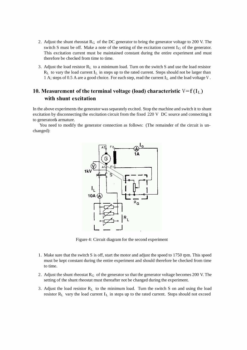
10. Measurement of the terminal voltage (load) characteristic V=f (IL)
with shunt excitation
In the above experiments the generator was separately excited. Stop the machine and switch it to shunt excitation by disconnecting the excitation circuit from the fixed 220 V DC source and connecting it to generator’s armature.
You need to modify the generator connection as follows: (The remainder of the circuit is un- changed):
G
Figure 4: Circuit diagram for the second experiment
1. Make sure that the switch S is off, start the motor and adjust the speed to 1750 rpm. This speed must be kept constant during the entire experiment and should therefore be checked from time to time.
2. Adjust the shunt rheostat RG of the generator so that the generator voltage becomes 200 V. The
setting of the shunt rheostat must thereafter not be changed during the experiment.
3. Adjust the load resistor RL to the minimum load. Turn the switch S on and using the load resistor RL vary the load current IL in steps up to the rated current. Steps should not exceed
1 A if possible; steps of 0.5 A are a good choice. For each step, read the current I L and voltage V .
Check the speed and do not change setting of the shunt rheostat RG.
Table 2: Load characteristic Separate Shunt
IF = const IL, A VT , V IL, A VT , V
11 Clean up
Turn off the power supply switches. Turn off the switch S. Disconnect the equipment and remove all wire from the bench. The AVOs must be turned off as well. Please remove any labels from the rheostats and motors.
12 Laboratory questions
Answer the following questions. Question 1. What are ratings of the DC machines in this laboratory experiment?
Motor: Generator Briefly explain the meaning of these ratings and how did you use them
Question 2. Draw the measured no-load characteristic for increasing and decreasing I F at 1750 and 1500
rpm, respectively, in the same coordinates with common IF axis. Use the grid provided below or draw the graph on graph paper and attach it to this report.
Why does the no-load characteristic differ for increasing and decreasing excitation current?
Why does the no-load characteristic differ for different speed of rotation?
Question 3. Draw the load characteristic for separate and shunt excitation in the same coordinates with
common IL axis.
Question 4. Using the obtained graphs and equivalent schematics of a shunt dc generator and a separately excited dc generator explain why for shunt generators, the terminal voltage V T drops off more as the load increases, as compared to the voltage drop off occurring in separately excited gen- erators.
Question 5. How does the voltage regulation of a dc shunt generator compare to that of a separately excited dc
generator? If possible, use results of the experiments to support the answer. Question 7. In the first experiment (Section 7), the field current on the motor was adjusted to a maximum
current. Can you explain, why was that done? What would happen if the motor were started with a small excitation current and no load?
Question 8. What are advantages and drawbacks of dc shunt and separately excited generators?


![CURRICULUM VITAE - Jazan Ucolleges.jazanu.edu.sa/phar/Documents/Dr. Pancholi-CV.pdf5 11. Pair wise binding affinity: 3D QSAR studies on a set of triazolo [1, 5-a] quinoxalines as antagonists](https://static.documents.pub/doc/80x56/5ac281bd7f8b9a213f8e686a/curriculum-vitae-jazan-pancholi-cvpdf5-11-pair-wise-binding-affinity-3d-qsar.jpg)


