1 Division of Physics and Applied Physics, School of Physical and Mathematical Sciences, Nanyang Technological University, 637371
Singapore, Singapore 2 Wenzhou Institute of Biomaterials and Engineering, Wenzhou 325001, China 3 Department of Physics, Faculty of Science, National University of Singapore, 117542 Singapore, Singapore 4 Graphene Research Center, Faculty of Science, National University of Singapore, 117546 Singapore, Singapore § These authors contributed equally to this work.
variation due to the coupling to the electronic mag‐
netoexcitations [10, 11]. Especially, the inter‐Landau‐
level (LL) electronic transitions 1,2
2,1LL and
0,1
1,0LL are
expected to have strong coupling with the G phonons
at about 5 and 30 T [11], respectively. Here, , 1
1,LL n n
n n
stands for the inter‐LL transitions both from 1Ln to
Ln and from L n
to 1Ln
( Ln represents the LL with
an index of n, where n = 0, 1, 2…). Raman spectroscopy
is a widely employed technique to study various
properties of graphene [12–21]. Recently, the MPR effect
in graphene‐related systems was observed through
magneto‐Raman spectroscopy (Raman spectroscopy
in a magnetic field) by several groups [22–26], where
the G phonons exhibit a clear magnetic dependent
variation. The Fermi level or filling factor was
anticipated and observed to greatly affect the MPR
effect in monolayer graphene [7–10]. Potemski’s
work observed the magneto‐phonon effect due to the
coupling between the G phonons and 0
1LL in mecha‐
nically exfoliated monolayer graphene [7]. From their
results, the sample was identified to be p‐type doped
and the filling factor value is between 2 and 6 at
about 25 T. However, this work only studied
accidentally doped graphene samples with carrier
concentrations typical for graphene deposited on
Si/SiO2 substrates. Kim et al. studied the MPR in
adsorption‐doped CVD‐grown monolayer graphene
samples [8]. The different doping levels were
obtained by adjusting annealing parameters and by
exposure to ambient pressure N2 gas or air, which
is not very tunable compared to electrically gated
graphene in the sense of uniformity or control. Very
recently, a comprehensive study of the electrical
tuning of the fundamental MPR induced by 1,00,1
LL
excitations in CVD grown graphene has been reported
[9]. The measurements were conducted at extremely
high constant magnetic fields around 25 T while
sweeping the gate voltage. However, a study of the
effect of relatively high doping levels on MPR under
a relatively low magnetic field is still missing and the
topic needs to be investigated.
Here, we report a study on the MPR effect involving 1,2
2,1LL in an electrically tuned monolayer graphene
by magneto‐Raman experiments. The carrier con‐
centration in the sample was tuned by a back gate, so
that the filling factor of LL under a magnetic field
was altered accordingly. Consequently, responses
of the G phonons of monolayer graphene to the
magnetic field with different gate voltages reflect the
filling factor effect on MPR. By tuning the Fermi level
to reach zero/large filling factors, we clearly show
that the MPR effect can be switched on/off in magnetic
fields around 4 T. Suspended exfoliated monolayer
graphene, which is newly studied, presents an obvious
MPR effect. In addition, an asymmetric line‐shape of
the Raman G band is observed in electrically neutral
graphene at low temperature and interpreted in terms
of Fano resonance.
2 Experimental
Graphene samples were prepared by mechanical
exfoliation from natural graphite crystals and trans‐
ferred onto a 300 nm SiO2/Si substrate [27]. Monolayer
graphene flakes were identified by using both optical
contrast spectroscopy and Raman spectroscopy
[28, 29]. Electron beam lithography was utilized to
define the geometry of electrodes [30], and then Ti
(5 nm)/Au (60 nm) were deposited to form contact
electrodes. The electron and hole mobilities can be
extracted from the transport data and the values are
about 9,490 and 8,050 cm2∙V–1∙s–1, respectively (Fig. S4
in the Electronic Supplementary Material (ESM)).
The low‐temperature magneto‐Raman measurements
were performed in a cryostat with a custom designed
confocal micro‐Raman spectroscopy/image system (see
Fig. 1(a)). A linearly polarized incident laser (Nd:YAG,
532 nm) with a ~1 μm beam size and a power less
than 5 mW was used to illuminate the sample. The
diameters of the optical fibers for delivering the laser
and collecting signal were 5 and 50 μm, respectively.
Similar to our previous experimental setup [25], both
co‐circular and cross‐circular polarized signals can be
simultaneously collected. Perpendicular magnetic
fields of up to 9 T were generated by a superconductor
magnet mounted inside the cryostat. A Keithley 4200
semiconductor characterization system was used to
measure the electrical response of the graphene device
and to provide a fixed gate voltage.
www.theNanoResearch.com∣www.Springer.com/journal/12274 | Nano Research
3 Nano Res.
3 Results and discussion
Raman spectra of the monolayer graphene device are
shown in Fig. 1(b). The Raman D peak which is
located around 1,350 cm–1 is undetectable, indicating
the high quality of the sample. To tune the doping
level, it is necessary to know the charge neutral point
(NP, also known as the Dirac point) of the graphene
sample [31]. We prefer to use gated Raman measure‐
ments rather than electrical transport measurements
to examine the NP value since Raman spectroscopy
can reflect the local properties. Gated Raman meas‐
urements were performed (at ~ 5 K) by sweeping the
gate voltage (Vg) from –40 to 40 V and selected spectra
are shown in Fig. 1(c). The frequency and full width
at half maximum (FWHM) of the G band as a function
of gate voltage were extracted by fitting each peak
into a single Lorentzian peak and are plotted in
Fig. 1(d). Softened G phonons can be observed at the
charge neutral Dirac point due to the Kohn anomaly
[13, 18] and hence the NP of the sample can be
determined to be at –6 V.
Magneto‐Raman spectra of the monolayer graphene
when Vg = –6 and 24 V are shown in Figs. 2(a) and 2(b),
respectively. In these spectra, the G bands show a
single peak profile with no obvious G peak split.
However, when Vg is –6 V, asymmetric broadening
on the lower frequency side of the G band can be
observed (see Fig. 2(c)). G peak asymmetry/splitting
has also been previously observed and was attributed
to the circular dichroism effect occurring only under
a high magnetic field [7, 32]. However, our measured
Raman G peak shows maximum asymmetry at a zero
magnetic field. Thus, the asymmetric line shape
presented here is most probably due to other reasons.
Fano resonance between the renormalized phonon
excitation and a continuum of excitonic many‐body
states, therefore, could be responsible and the peaks
can be fitted by the Breit–Wigner–Fano (BWF) line
shape [33, 34]
Figure 1 (a) A schematic for the experimental setup for the magneto-Raman measurements. (b) Raman spectra on monolayer graphene at room temperature (~300 K, black curve) and low temperature (~5 K, red curve). Inset is optical image of the graphene device. (c) Raman spectra of a graphene device under various gate voltages at 5 K. The red curve (Vg = –6 V) corresponds to the case when the Fermi level is brought near to the Dirac point. (d) Positions (black spheres) and widths (red spheres) of the G peak as a function of thegate voltage. Simulation results are shown in blue and green lines.
| www.editorialmanager.com/nare/default.asp
4 Nano Res.
2
00 2 2
0
[1 2( ) / ( )]( )
[1 4( ) / ]
qI I (1)
where 1/|q| is the asymmetry factor or coupling
coefficient, and 0I ,
0, and are the intensity,
uncoupled BWF peak frequency and broadening
parameter, respectively. In the limit q→∞, the line
shape is symmetric and shows the standard Lorentzian
profile, indicating a weak interference or coupling.
The extracted values for –1/q under various gate
voltages (see Fig. S5, in the ESM) are comparable to
previous work by Yoon et al. [33]. Both sets of –1/q
data are within the range of 0.08 to 0, and vanish
when the Fermi energy is sufficiently large (~0.2 eV
for both our sample and Yoon’s sample). When the
graphene is either electron or hole doped to a certain
extent, the values of –1/q are around 0. The absence
of Fano resonance in doped graphene is consistent
with a previous report and is attributed to the
suppressed excitonic processes [33]. The fitted –1/q
values as a function of magnetic field under three
different gate voltages are summarized in Fig. 2(d).
When the Fermi level of graphene is tuned to be near
Dirac point, the –1/q values are all non‐zero and show
a maximum value at 0 T. The presence of a magnetic
field splits the continuum band structure of graphene
into discrete Landau levels, thereby weakening Fano
resonance as the magnetic field increases. A similar
modification of Fano resonance by magnetic fields
has been reported in quantum wells [35, 36]. Note that
the Fano resonance is not considered to be an important
factor affecting the MPR effect in this work.
The evolution of the frequency and the FWHM of
the G peak for the monolayer graphene with magnetic
field at three different gate voltages are shown in
Figs. 3(a) and 3(b), respectively. As shown in Fig. 3(a),
Figure 2 Raman spectra of monolayer graphene at different magnetic fields measured at low temperature (~ 5 K) with back gate voltagesof (a) Vg = –6 and (b) 24 V applied. Blue spheres represent raw data and the red dashed lines are the fitting curves. Green dashed lines are a guide to the eyes. (c) Comparison of the G peak line shapes for a graphene sample in the cases of the neutral point (Vg = –6 V) and electrically doped (Vg = 24 V; Vg = –36 V). The solid lines are obtained by fitting the data points to the BWF line shape using Eq. (1). (d) The summarized asymmetry factor –1/q for the Raman spectra recorded under these three gate voltages.
www.theNanoResearch.com∣www.Springer.com/journal/12274 | Nano Research
5 Nano Res.
it is clear that the frequency of the G phonons shows
a magnetic field dependent variation when Vg is –6 V.
In detail, the G band frequency decreases (with
fluctuations) before reaching its minimum value of
about 1,589.5 cm–1 at about 4 T. After this point, it keeps
rising to its maximum value of about 1,593.0 cm–1
at 9 T. For the FWHM values shown in Fig. 3(b), the
maximum is located at about 3.5 T and then the
FWHM value decreases with further increases in
the magnetic field. In contrast, both the frequency
and the FWHM of the G peak show weak magnetic
dependence when the sample is highly n‐type or
p‐type doped.
The results shown in Fig. 3 can be well interpreted
by the MPR theory. Discrete LLs appear when the
graphene is subjected to a magnetic field. The energy
of the LL with an index of n (nE ) is proportional to
the square root of the index n and the magnetic field
strength B [37, 38]
2
Fsgn( ) 2
nE n e v B n
where vF is the Fermi velocity, and n>0 and n<0
represent electrons and holes, respectively. The energy
of the inter‐LL electronic excitations for , 1
1,LL n n
n n (which
is denoted by
, 1
1,
n n
n nE here) is
, 1 2
1, F( 1 ) 2n n
n nE n n e V B (2)
MPR occurs when the energy of the inter‐LL transitions
is equal to the E2g phonon energy at a certain B field
(i.e. the resonant magnetic field), which leads to
magnetic oscillation of the G‐band phonons. According
to Ando’s calculations, the spectral width will become
a maximum and the frequency will changing rapidly
Figure 3 The evolutions of (a) the BWF peak frequency and (b) the width of the G peak for the monolayer graphene with magnetic field under different gate voltages. Vg values are –6, 24 and –36 V for black, blue and green curves, respectively. Simulation results arealso shown. Schematic images for different doping situations in monolayer graphene when different back gate voltages are applied at B =3.5 T. Discrete LLs are labeled with corresponding LL indexes. Fermi levels in these cases are also indicated. Vertical blue lines indicatethe inter-LL transitions. (c) Vg = –6 V. The indicated inter-LL transitions are possible in this case. (d) Vg = 24 V. The indicated inter-LLtransitions are suppressed in this case. (e) Vg = –36 V. The indicated inter-LL transitions are suppressed in this case.
(1)
| www.editorialmanager.com/nare/default.asp
6 Nano Res.
at the resonant B field [10]. We therefore deduce that
MPR occurs at about 3.5 T and is associated with
the 1,2
2,1LL transition according to our experimental
data. Considering the MPR condition of 1,2
2,1E =
196.8 meV (the G phonon energy is ~ 196.8 meV at 5 K
without a magnetic field), the Fermi velocity vF of the
sample can be calculated to be about 1.21 × 10⁶ m2∙s–1.
This vF value is reasonable [39, 40] and agrees well
with the values given in other reports for monolayer
graphene [37, 38, 41]. We also carried out simulations
using the same model as in Potemski’s work [42] (see
details in the ESM), and extracted the following
parameters: The interaction parameter 35 10 , the broadening factor 1400 cm 49.6 meV , the
phonon energy at zero magnetic field 1
01,586.6 cm ,
and the Fermi velocity Fv 1.21 × 10
6 m2∙s–1. These
values are comparable to earlier reports [7, 26, 32, 42].
Furthermore, substituting these values in Ando’s model
for the phonon anomaly phenomenon (see details in
the ESM) at B = 0 T [32], the experimental data can be
fairly well reproduced as shown in Fig. 1(d). Now we would like to discuss the doping effect on
MPR in the monolayer graphene sample. When a Vg
of –6 V was applied to the sample, its filling factor is around 0. In this case, only the central LL (n = 0) is
large filling factors, can block the inter‐LL electronic
excitations and thus suppress MPR effect in graphene.
The filling factor in monolayer graphene can be
calculated [41, 43, 44]
s
/
n
eB h
s g g Dirac
/n C V V e (3)
s( 1 / 2)g n
where is the filling factor and sn is the carrier
density. sg = 4, accounting for the spin degeneracy and
sublattice degeneracy. Cg denotes the gate capacitance
and is ~115 aF∙μm–2. Based on Eq. (3), the filling factor
in our sample is = 26 under a field of B = 3.5 T when
Vg = 24 V/–36 V, which means that the electrons will
fill to the LL with index n = ±6. Schematic images for
these three different doping situations (B = 3.5 T) in
monolayer graphene are shown in Figs. 3(c)–3(e).
Consequently, the inter‐LL excitations 1,2
2,1LL become
inactive in both cases resulting in the suppression of
their hybridization with the G phonon.
The MPR effect in several as‐prepared mechanically
exfoliated supported and suspended monolayer
graphene samples was also investigated. Here we
should mention that weak residual strains (less than
1%) may exist in the samples after cooling to low
temperatures [16]. The interpretation of the data is
not be affected, however, because the weak strain
should not significantly affect the MPR [9, 45]. The
results for a suspended monolayer graphene are
displayed in Fig. 4. There are more than ten suspended
regions in this graphene sample (Fig. 4(a)) and distinct
magnetic field dependent variations of the frequency
and the FWHM of the G peak can be observed from
all randomly measured regions. The results shown in
Fig. 4(b) are obtained from the region numbered 5 and
Figure 4 (a) Optical image of the as exfoliated sample on a substrate with patterned holes. More than 10 holes on the substrate were covered by this monolayer graphene (indicated by the red arrow, holes are numbered to identify different suspended graphene areas). The diameter of a hole is about 3 m while the laser spot size is about 1 m. (b) G peak center (black spheres) and width (blue spheres) as a function of magnetic field for the suspended monolayer graphene region numbered 5 (indicated by the blue square).
www.theNanoResearch.com∣www.Springer.com/journal/12274 | Nano Research
7 Nano Res.
the resonant field is about 3.6 T. Notice that the
oscillation in the suspended sample is the most obvious
among all the graphene samples studied in this work.
Comparing the widths of their G bands (Figs. 3(b)
and 4(b)), we can see that the suspended graphene
sample possesses a narrower G band than the supported
graphene, suggesting a longer phonon lifetime. We
suspect that the longer phonon lifetime in the sample
represents a higher quality, which is an important
factor affecting the MPR in graphene [46]. Due to the
elimination of both the substrate effect and the
influence caused by device fabrication, the suspended
graphene can have the longest lifetime of all these
samples. This assumption can be further confirmed
by the fact that the graphene‐like region on the graphite
substrate with a much narrower G peak width of
~4 cm–1 shows a more prominent MPR effect than
other graphene samples [22, 25].
4 Conclusions
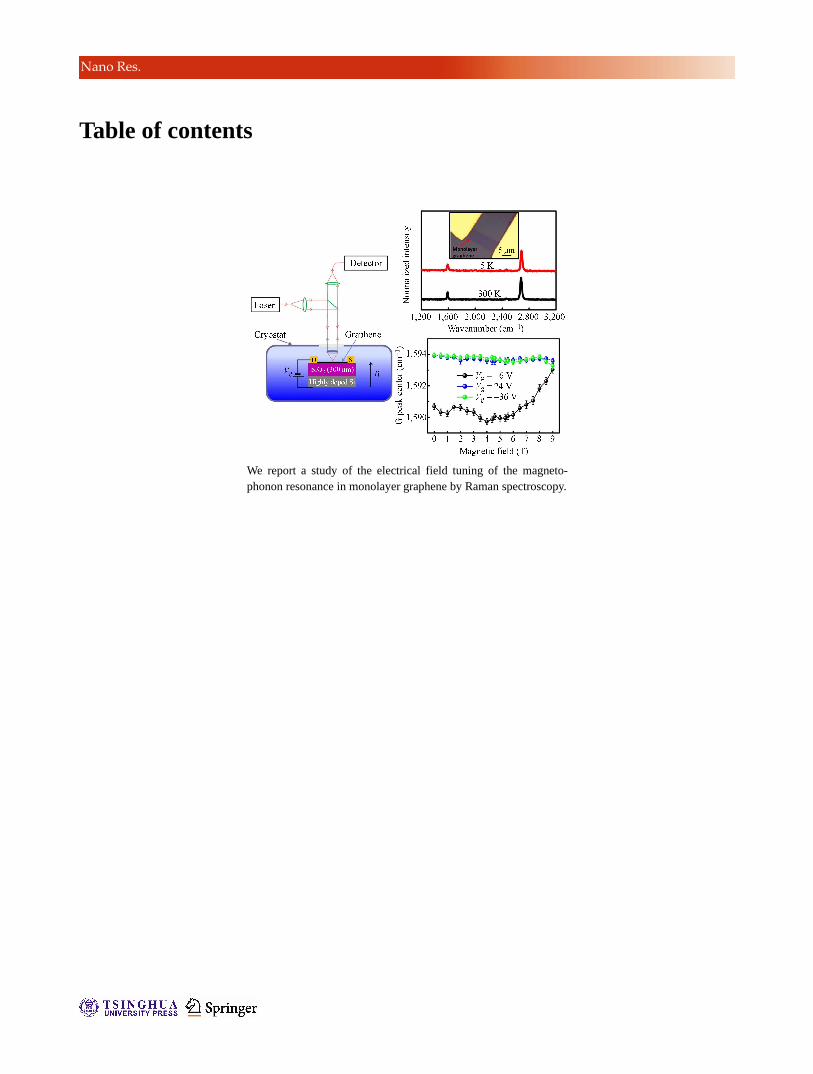
We have reported magneto‐Raman results obtained
by sweeping relatively low magnetic fields in
mechanically exfoliated monolayer graphene under
different situations: (1) Fabricated as field‐effect devices
and electrically tuned to fixed doping levels; (2)
supported on SiO2/Si; (3) suspended from the substrate.
The MPR effect involving 1,2
2,1LL transitions appears
when the filling factor is near zero, and disappears
when the sample is highly doped due to Pauli blocking.
A filling factor effect on MPR in monolayer graphene
is thus experimentally observed and matches well
with theoretical predictions. This is the first reported
MPR study of suspended samples and the fact that
they show the clearest oscillations of all the studied
samples indicates the importance of sample quality. In
addition, Fano resonance is proposed to explain the
observed asymmetric line shape of the Raman G band
in electrically neutral graphene. Furthermore, the
magnetic field effect on the Fano resonance has been
demonstrated in our work. A detailed understanding
of the magnetic field induced modification of Fano
resonance in graphene and other 2D materials could
be useful in future work. These findings extend our
knowledge of MPR in graphene and may trigger
pertinent theoretical studies. We believe that the
findings here will be of interest to the graphene and
other 2D system research communities.
Acknowledgement
This work is supported by the Singapore National
Research Foundation under NRF RF award (No.
NRF‐RF2010‐07) and MOE Tier 2 (No. MOE2012‐T2‐
2‐049). We thank Jeil Jung, Penghui Yao and Jingzhi
Shang for their helpful discussion.
Electronic Supplementary Material: Supplementary
material (calibration test for the custom designed
magneto‐Raman system, magneto‐Raman scattering
study on supported monolayer graphene, simulations
for monolayer graphene, mobility of the carriers in the
graphene device, phonon anomalies in the graphene
device and Fano resonance in the graphene device) is
available in the online version of this article at http:
//dx.doi.org/10.1007/s12274‐014‐0594‐9.
References
[1] Barnes, D. J.; Nicholas, R. J.; Peeters, F. M.; Wu, X. G.;
Devreese, J. T.; Singleton, J.; Langerak, C. J. G. M.; Harris,
J. J.; Foxon, C. T. Observation of optically detected magne-
tophonon resonance. Phys. Rev. Lett. 1991, 66, 794–797.
[2] Vaughan, T. A.; Nicholas, R. J.; Langerak, C. J. G. M.;
Murdin, B. N.; Pidgeon, C. R.; Mason, N. J.; Walker, P. J.
Direct observation of magnetophonon resonances in Landau-
level lifetimes of a semiconductor heterostructure. Phys. Rev.
B 1996, 53, 16481–16484.
[3] Nicholas, R. J. The magnetophonon effect. Prog. Quantum
Electron. 1985, 10, 1–75.
[4] Firsov, Y. A.; Gurevich, V. L.; Parfeniev, R. V.; Shalyt, S. S.
Investigation of a new type of oscillations in the
magnetoresistance. Phys. Rev. Lett. 1964, 12, 660–662.
[5] Tsui, D. C.; Englert, T.; Cho, A. Y.; Gossard, A. C.
Observation of magnetophonon resonances in a two-
dimensional electronic system. Phys. Rev. Lett. 1980, 44,
341–344.
[6] Stradling, R. A.; Wood, R. A. The magnetophonon effect in
III-V semiconducting compounds. J. Phys. C: Solid State
Phys. 1968, 1, 1711.
[7] Kossacki, P.; Faugeras, C.; Kühne, M.; Orlita, M.; Mahmood,
A.; Dujardin, E.; Nair, R. R.; Geim, A. K.; Potemski, M.
Circular dichroism of magnetophonon resonance in doped
graphene. Phys. Rev. B 2012, 86, 205431.
| www.editorialmanager.com/nare/default.asp
8 Nano Res.
[8] Kim, Y.; Poumirol, J. M.; Lombardo, A.; Kalugin, N. G.;
Georgiou, T.; Kim, Y. J.; Novoselov, K. S.; Ferrari, A. C.;
Kono, J.; Kashuba, O. et al. Measurement of filling-factor-
dependent magnetophonon resonances in graphene using
raman spectroscopy. Phys. Rev. Lett. 2013, 110, 227402.
[9] Leszczynski, P.; Han, Z.; Nicolet, A. A. L.; Piot, B. A.;
Kossacki, P.; Orlita, M.; Bouchiat, V.; Basko, D. M.;
Potemski, M.; Faugeras, C. Electrical switch to the resonant
magneto-phonon effect in graphene. Nano Lett. 2014, 14,
1460–1466.
[10] Ando, T. Magnetic oscillation of optical phonon in graphene.
J. Phys. Soc. Jpn. 2007, 76, 024712.
[11] Goerbig, M. O.; Fuchs, J. N.; Kechedzhi, K.; Fal’ko, V. I.
Filling-factor-dependent magnetophonon resonance in
1 Division of Physics and Applied Physics, School of Physical and Mathematical Sciences, Nanyang Technological University, 637371Singapore, Singapore
2 Wenzhou Institute of Biomaterials and Engineering, Wenzhou 325001, China 3 Department of Physics, Faculty of Science, National University of Singapore, 117542 Singapore, Singapore 4 Graphene Research Center, Faculty of Science, National University of Singapore, 117546 Singapore, Singapore § These authors contributed equally to this work.
Supporting information to DOI 10.1007/s12274-014-0594-9
1 Calibration test for the custom designed magneto‐Raman system
A commercial calibration grating sample [S1] (Anfatec‐UMG02) was used to test our system. A SEM image of
the calibration sample is shown in Fig. S1(a). The chess pattern structure makes it suitable for the lateral
calibration. Confocal Rayleigh mapping images at room temperature and low temperature are shown in
Figs. S1(b) and S1(c), respectively. From these test results, it is concluded that the spatial resolution can reach
about 1 m in our system.
Figure S1 Calibration of our custom designed system. (a) SEM image of the sample which was used to calibrate our experimental setup. (b) Confocal mapping image of the calibration sample at room temperature (about 300 K). (c) Confocal mapping image of the calibration sample at low temperature (about 5 K).
2 Magneto‐Raman scattering study on supported monolayer graphene
Magneto‐Raman scattering experiments were carried out on several supported monolayer graphene samples.
Exfoliated samples were prepared on top of the commonly used SiO2 (300 nm)/Si substrate. An optical image of
one representative graphene sample is shown in Fig. S2(a), where the monolayer region is indicated by the red
arrow. Magnetic field dependent evolution of the G peak center and the FWHM for the monolayer graphene
are shown in Fig. S2(b). This result is similar to that for the gated graphene when Vg is –6 V (as shown in Fig. 3).
A possible reason for this is that this as‐exfoliated sample is nearly intrinsic or not highly doped at low
temperature in the vacuum environment.
Figure S2 Magneto-Raman scattering in supported monolayer graphene. (a) Optical image of the as-exfoliated sample which contains monolayer graphene (indicated by the red arrow). (b) Evolution of the G peak center and the FWHM under magnetic fields for the monolayer graphene.
3 Simulation studies on the monolayer graphene
Based on the prediction by Ando [S2], an equation (Eq. (S1)) was developed in Potemski’s work [S3] to analysis
the magneto‐phonon resonance in graphene. The same model was used here to extract the parameters
2 2 2
0 0 1 2 20
12 k
k kk
TE
Ti T (S1)
i (S2)
2
1 1 F( 1) , 2 ,( 0,1,2,...)
kT k k E E e v B k (S3)
where 0 stands for the phonon energy at B = 0 T, and stand for the energy and width of the G phonon
under magnetic field, is the interaction strength between the G phonon and the magnetoexcitation, stands for the broadening of the magnetoexcitation,
kT denotes the energy of the magnetoexcitation and
Fv represents
the Fermi velocity.
Experimental data and simulation results are compared in Fig. 3. Extracted values are: the interaction
strength 35 10 , the broadening factor 1400 cm 49.6 meV , the phonon energy at zero magnetic
www.theNanoResearch.com∣www.Springer.com/journal/12274 | Nano Research
Nano Res.
field 1
01,586.6 cm , and the Fermi velocity
Fv 1.21 × 10
6 m2∙s–1. They are reasonable and comparable to
previous results.
Although the detailed field dependent features such as the oscillations of both G peak center and FWHM
found in the theoretical curves are not clearly reflected in the experimental data, the dominant feature near B =
3.5 T corresponding to the strongest MPR due to the 1,2
2,1LL transition can be seen. The deviation between the
theoretical and experimental data could be due to the relatively poor quality of the sample and/or the
uniformly distributed non‐intentional doping from the substrate.
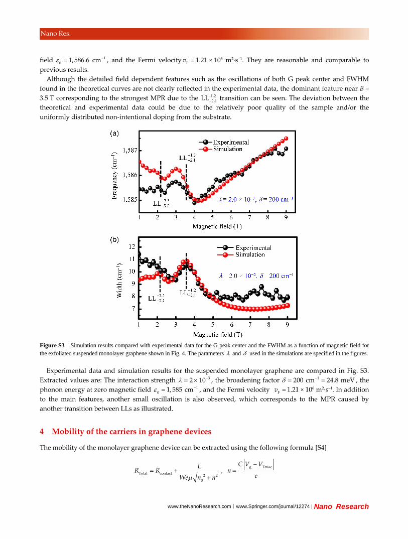
Figure S3 Simulation results compared with experimental data for the G peak center and the FWHM as a function of magnetic field for the exfoliated suspended monolayer graphene shown in Fig. 4. The parameters and used in the simulations are specified in the figures.
Experimental data and simulation results for the suspended monolayer graphene are compared in Fig. S3.
Extracted values are: The interaction strength 32 10 , the broadening factor 1200 cm 24.8 meV , the
phonon energy at zero magnetic field 1
01,585 cm , and the Fermi velocity
Fv 1.21 × 10
6 m2∙s–1. In addition
to the main features, another small oscillation is also observed, which corresponds to the MPR caused by
another transition between LLs as illustrated.
4 Mobility of the carriers in graphene devices
The mobility of the monolayer graphene device can be extracted using the following formula [S4]
Total contact
2 2
0
LR R
We n n,
g DriacC V V
ne
| www.editorialmanager.com/nare/default.asp
Nano Res.
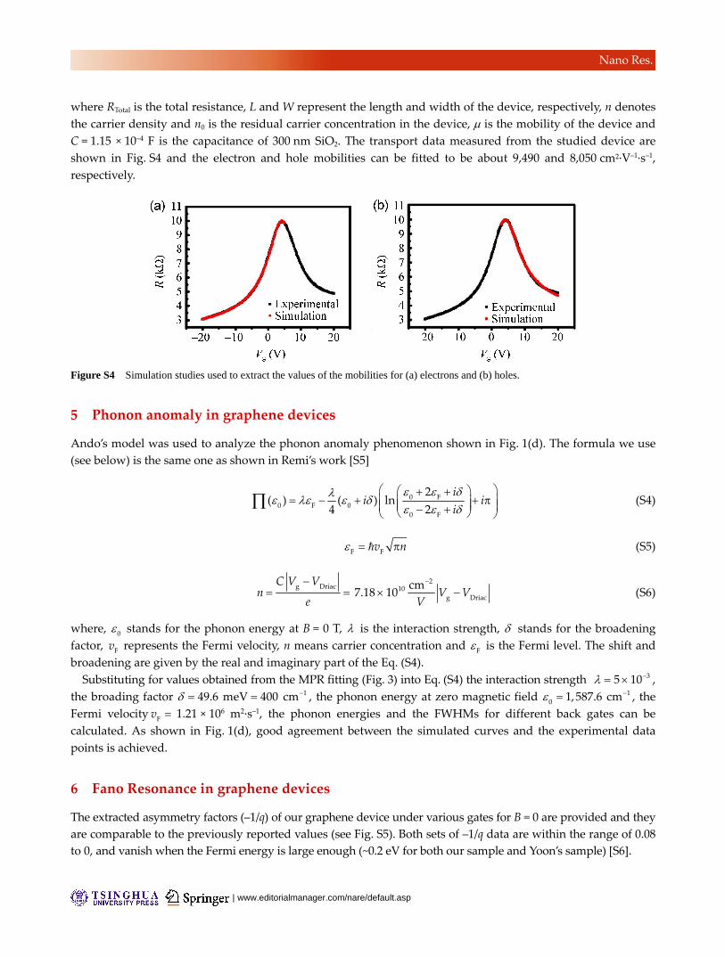
where RTotal is the total resistance, L and W represent the length and width of the device, respectively, n denotes
the carrier density and n0 is the residual carrier concentration in the device, is the mobility of the device and
C = 1.15 × 10⁻⁴ F is the capacitance of 300 nm SiO2. The transport data measured from the studied device are
shown in Fig. S4 and the electron and hole mobilities can be fitted to be about 9,490 and 8,050 cm2∙V–1∙s–1,
respectively.
Figure S4 Simulation studies used to extract the values of the mobilities for (a) electrons and (b) holes.
5 Phonon anomaly in graphene devices
Ando’s model was used to analyze the phonon anomaly phenomenon shown in Fig. 1(d). The formula we use
(see below) is the same one as shown in Remi’s work [S5]
0 F0 F 0
0 F
2( ) ( ) ln
4 2
ii i
i (S4)
F F
v n (S5)
2g Driac 10
g Driac
cm7.18 10
C V Vn V V
e V (S6)
where, 0 stands for the phonon energy at B = 0 T, is the interaction strength, stands for the broadening
factor, Fv represents the Fermi velocity, n means carrier concentration and
F is the Fermi level. The shift and
broadening are given by the real and imaginary part of the Eq. (S4).
Substituting for values obtained from the MPR fitting (Fig. 3) into Eq. (S4) the interaction strength 35 10 ,
the broading factor 149.6 meV 400 cm , the phonon energy at zero magnetic field 1
01,587.6 cm , the
Fermi velocity Fv 1.21 × 10
6 m2∙s–1, the phonon energies and the FWHMs for different back gates can be
calculated. As shown in Fig. 1(d), good agreement between the simulated curves and the experimental data
points is achieved.
6 Fano Resonance in graphene devices
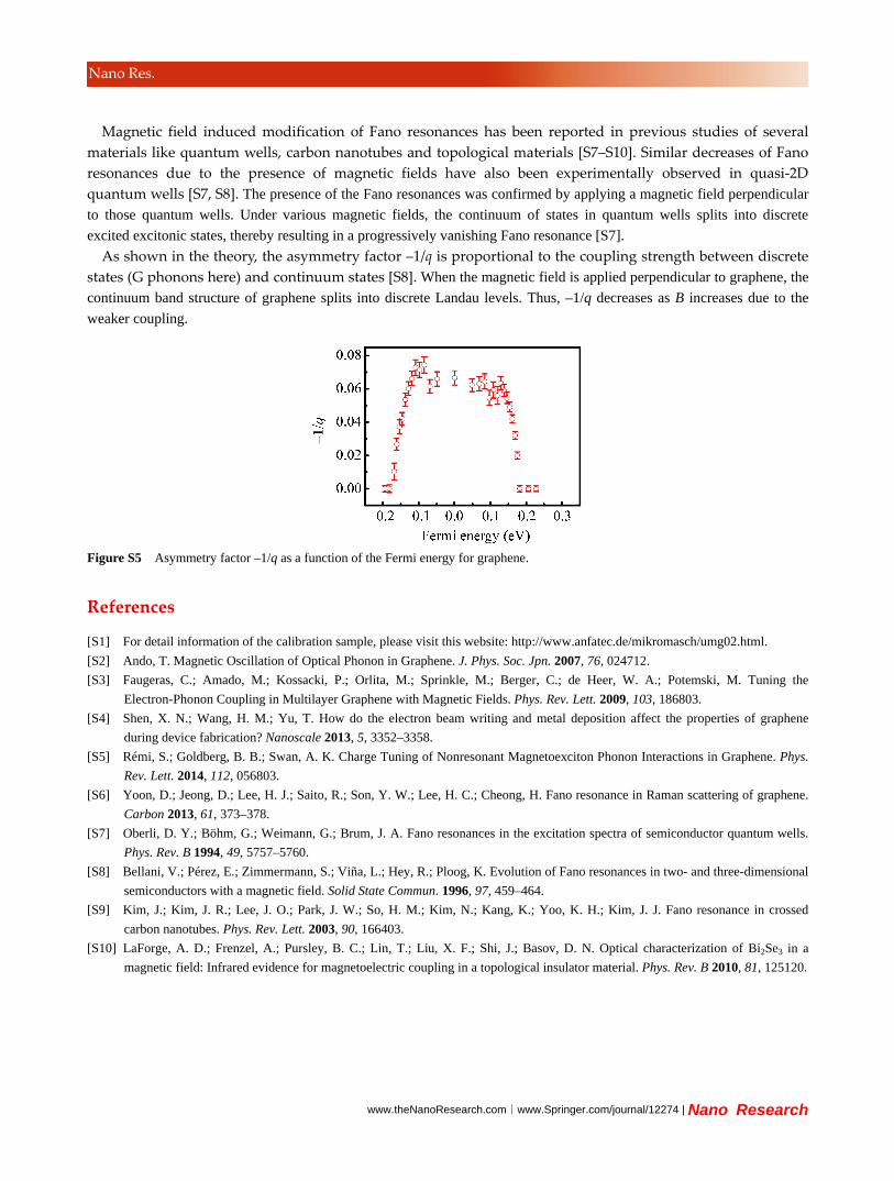
The extracted asymmetry factors (–1/q) of our graphene device under various gates for B = 0 are provided and they
are comparable to the previously reported values (see Fig. S5). Both sets of –1/q data are within the range of 0.08
to 0, and vanish when the Fermi energy is large enough (~0.2 eV for both our sample and Yoon’s sample) [S6].
www.theNanoResearch.com∣www.Springer.com/journal/12274 | Nano Research
Nano Res.
Magnetic field induced modification of Fano resonances has been reported in previous studies of several
materials like quantum wells, carbon nanotubes and topological materials [S7–S10]. Similar decreases of Fano
resonances due to the presence of magnetic fields have also been experimentally observed in quasi‐2D
quantum wells [S7, S8]. The presence of the Fano resonances was confirmed by applying a magnetic field perpendicular
to those quantum wells. Under various magnetic fields, the continuum of states in quantum wells splits into discrete
excited excitonic states, thereby resulting in a progressively vanishing Fano resonance [S7].
As shown in the theory, the asymmetry factor –1/q is proportional to the coupling strength between discrete
states (G phonons here) and continuum states [S8]. When the magnetic field is applied perpendicular to graphene, the
continuum band structure of graphene splits into discrete Landau levels. Thus, –1/q decreases as B increases due to the
weaker coupling.
Figure S5 Asymmetry factor –1/q as a function of the Fermi energy for graphene.
References
[S1] For detail information of the calibration sample, please visit this website: http://www.anfatec.de/mikromasch/umg02.html.
[S2] Ando, T. Magnetic Oscillation of Optical Phonon in Graphene. J. Phys. Soc. Jpn. 2007, 76, 024712.
[S3] Faugeras, C.; Amado, M.; Kossacki, P.; Orlita, M.; Sprinkle, M.; Berger, C.; de Heer, W. A.; Potemski, M. Tuning the
Electron-Phonon Coupling in Multilayer Graphene with Magnetic Fields. Phys. Rev. Lett. 2009, 103, 186803.
[S4] Shen, X. N.; Wang, H. M.; Yu, T. How do the electron beam writing and metal deposition affect the properties of graphene
during device fabrication? Nanoscale 2013, 5, 3352–3358.
[S5] Rémi, S.; Goldberg, B. B.; Swan, A. K. Charge Tuning of Nonresonant Magnetoexciton Phonon Interactions in Graphene. Phys.
Rev. Lett. 2014, 112, 056803.
[S6] Yoon, D.; Jeong, D.; Lee, H. J.; Saito, R.; Son, Y. W.; Lee, H. C.; Cheong, H. Fano resonance in Raman scattering of graphene.
Carbon 2013, 61, 373–378.
[S7] Oberli, D. Y.; Böhm, G.; Weimann, G.; Brum, J. A. Fano resonances in the excitation spectra of semiconductor quantum wells.
Phys. Rev. B 1994, 49, 5757–5760.
[S8] Bellani, V.; Pérez, E.; Zimmermann, S.; Viña, L.; Hey, R.; Ploog, K. Evolution of Fano resonances in two- and three-dimensional
semiconductors with a magnetic field. Solid State Commun. 1996, 97, 459–464.
[S9] Kim, J.; Kim, J. R.; Lee, J. O.; Park, J. W.; So, H. M.; Kim, N.; Kang, K.; Yoo, K. H.; Kim, J. J. Fano resonance in crossed
carbon nanotubes. Phys. Rev. Lett. 2003, 90, 166403.
[S10] LaForge, A. D.; Frenzel, A.; Pursley, B. C.; Lin, T.; Liu, X. F.; Shi, J.; Basov, D. N. Optical characterization of Bi2Se3 in a
magnetic field: Infrared evidence for magnetoelectric coupling in a topological insulator material. Phys. Rev. B 2010, 81, 125120.