LABORATORY MANUAL For DEPARTMENT OF ELECTRICAL ENGINEERING Subject Name:- ELECTRICAL MACHINES-1 Subject code:- ET-215-E OM INSTITUTE OF TECHNOLOGY AND MANAGEMENT V.P.O. : Juglan,12 KM stone, Hisar-Chandigarh Road, National Highway - 65 District. : Hisar Haryana
V.P.O. : Juglan,12 KM stone, Hisar-Chandigarh Road, National Highway - 65
District. : Hisar Haryana
INDEX
S.No. Experiments Page No. 1.
To find turns ratio & polarity of a 1-phase
transformer.
1-3
2. To perform open & short circuit tests on a 1-
phase transformer.
4-7
3. To perform Sumpner's Back to back test on 1-
phase transformers.
8-12
4. Parallel operation of two 1-phase transformers.
13-15
5. To convert three phase to 2-phase By Scott-
connection.
16-18
6. To perform load test on DC shunt generator.
19-21
7. Speed control of DC shunt motor.
22-24
8. Swinburne’s test of DC shunt motor.
25-30
9. Hopkinson’s test of DC shunt M/Cs.
32-35
10. Ward Leonard method of speed control.
36-37
ET-215-E ELECTRICAL MACHINE LAB-I
L T P External : 70 Marks
- - 2 Internal : 30 Marks
Total : 100Marks
Duration of Exam : 3 Hrs.
LIST OF EXPERIMENTS
1. To find turns ratio & polarity of a 1-phase transformer.
2. To perform open & short circuit tests on a 1-phase transformer.
3. To perform Sumpner's Back to back test on 1-phase transformers.
4. Parallel operation of two 1-phase transformers.
5. To convert three phase to 2-phase By Scott-connection.
6. To perform load test on DC shunt generator.
7. Speed control of DC shunt motor.
8. Swinburne’s test of DC shunt motor.
9. Hopkinson’s test of DC shunt M/Cs.
10. Ward Leonard method of speed control.
NOTE: At least 10 experiments be performed in the semester. At least seven experiments should
be performed from above list. Remaining 3 experiments may either be performed from the above
list or designed & set by concerned institution as per scope of syllabus
OM INSTITUTE OF TECHNOLOGY AND MANAGEMENT
JUGLAN,HISAR
PRACTICAL MANUAL INSTRUCTION SHEET
Page
No.
1/3
Name of Subject:- Electrical Machines-1 Lab
Subject Code:- ET-215-E
EXPERIMENT: To find Turn’s Ratio & Polarity of a 1-phase Transformer
Electrical Engineering Department Semester -III Exp.No.ET-EX.01
Apparatus Required
Sr. No. Description Range Type Qty
1. Transformer - - 1 No
2. AC Voltmeter (0-500V) M.C 3 No
3. Variac - - 1 No
4. Connecting leads
Circuit Diagram
Theory
Polarity Test:- On the primary side of a two winding transformer, one terminal is positive
with respect to the other one at any instant. At the instant, one terminal of the secondary
winding is positive with respect to the other one. Polarity test is performed to determine the
terminals having the same instantaneous polarity. The relative polarities of the primary and
secondary terminals at any instant must be known for connecting windings of the same
transformer in parallel, or series or for interconnecting two or more transformer in parallel, or
for connecting single phase transformers for polyphase transformations of voltages. In
subtractive polarity, the voltage between A1 and a1 is reduced. The leads connected to these
terminals and the two windings are, therefore, not subjected to high voltages stress. On the
other hand in additive polarity the two windings and leads connected to A1, A2, a1 and a2 are
subjected to high voltage stresses. This is the reason that subtractive polarity is preferred over
additive polarity.
Voltage ratio test: - The true ratio is based on trun-ratio. If the secondary and primary
voltages are measured on no load, their ratio is very nearly equal to the true value.
Measurement of primary and secondary currents in short circuit test also gives fairly accurate
result.
Procedure
Step 1:- As per circuit diagram, terminals A1 and A2 are marked plus and minus arbitrarily.
Step 2:- Now terminal A1 is connected to one end of secondary winding and a voltmeter is
connected between A2 and the other end of secondary winding.
Step 3:- A voltage V3 of suitable value is applied to the high voltage winding.
Step 4:- Measure E1 and E2 by connecting voltmeters V1 and V2 across two windings.
Step 5:- If the voltmeter V3 reading, measured in step 3, is equal to E1 ,-E2, then secondary
terminal connected to A1is positive and other terminal –ve.
Step 6:- If the voltmeter V3 reading is equal to E1 and E2, then secondary terminal connected
to A1 is –ve and other terminal +ve.
Observation Table
(A) Subtractive Polarity
S.No Reading for V1 Reading for V2 Reading for V3 V3=V2-V1
(B) Additive Polarity
S.No Reading for V1 Reading for V2 Reading for V3 V3=V2+V1
Voltage Ratio
Procedure:
Step1:- Connect one voltmeter on the primary and the other on the secondary side, on open
circuit,
Step 2:- Note down readings of two voltmeters.
Observation
S.No Reading for V1 Reading for V2 Reading for V3 Voltage
ratio=V2/V1
Calculation
OM INSTITUTE OF TECHNOLOGY AND MANAGEMENT
JUGLAN,HISAR
PRACTICAL MANUAL INSTRUCTION SHEET
Page No.
2/3
Name of Subject:- Electrical Machines-1 Lab Subject Code:- ET-215-E
Exp.No.ET-EX.01
Precaution
1) All connections should be tight.
2) All steps should be followed carefully.
3) Readings and calculations should be taken carefully.
4) Don’t touch the live terminals.
Result:-
When the voltmeter reads the difference E1-E2, the transformer is said to possess a
subtractive polarity and when the voltmeter reads E1+E2, the transformer is said to possess a
additive polarity. The voltage ratio of a transformer is obtained from the readings of two
voltmeters one on the primary, and the other on the secondary side, an open circuit.
V2/V1=open circuit
Viva Voce
Q1) What is the difference between ideal and practical transformers?
Q2) What happens when a transformer is connected with DC supply?
Q3) What is the need for performing polarity test on a transformer?
Q4) What is the need for performing voltage ratio test on a transformer?
OM INSTITUTE OF TECHNOLOGY AND MANAGEMENT
JUGLAN,HISAR
PRACTICAL MANUAL INSTRUCTION SHEET
Page No.
3/3
Name of Subject:- Electrical Machines-1 Lab Subject Code:- ET-215-E
Exp.No.ET-EX.01
OM INSTITUTE OF TECHNOLOGY AND MANAGEMENT
JUGLAN,HISAR
PRACTICAL MANUAL INSTRUCTION SHEET
Page
No.
1/4
Name of Subject:- Electrical Machines-1 Lab
Subject Code:- ET-215-E
EXPERIMENT: To perform Open and Short Circuit test on a 1-phase transformer.
Electrical Engineering Department Semester -III Exp.No.ET-EX.02
(A) Open Circuit Test Apparatus Required:
Sr. No. Description Range Quantity Type
1. Voltmeter 0-150V 1.No M.I
2. Ammeter 0-2.5A 1.No M.I
3. Wattmeter 2.5A/150v 1.No Dynamomteter
4. Auto Transformer 230/0-270V,8A 1.No 1-phase wire
wound
5. Fuses 5A 2.Nos -
Circuit Diagram:-
Theory: Transformer is a static device which transfers electrical power from one circuit to
another circuit either by step up or step down the voltage with corresponding decrease increase in
the current, with out changing the frequency.
OC Test:-The main aim of this test is to determine the Iron losses & No- load current of the T/F
which are helpful in finding Ro & Xo.In this test generally supply will be given to primary and
secondary kept open. Since secondary is opened a small current(magnetizing current will flow
and it will be 5 to 10% of full load current. The wattmeter connected in primary will give directly
the Iron losses (core losses).
Procedure:
Step 1: Give connections as per the circuit diagram.
Step 2: Switch-ON the supply and apply rated voltage to the primary of the winding by
using the auto transformer.
Step 3:Note the readings of Ammeter, Voltmeter & Wattmeter
Graph: A graph is drawn between P.F and % regulation by taking P.F on X- axis and %
regulation on Y-axis.
Observation Table:-
V0 (Volts) I0 (Amperes) W0( watts)
(B) Short Circuit Test:-
Apparatus Required:-
Sr. No. Description Range Quantity Type
1. Voltmeter 0-50V 2.Nos M.I
2. Ammeter 0-5A 1.No M.I
3. Wattmeter 5A/50V 1.No Dynamometer
(UPF)
4. Auto Transformer 230/0-270V,8A 1.No 1-phase wire
wound
5. Fuses 5A 2.Nos -
Circuit Diagram:-
SC Test: The main aim of this test is to determine the full load copper losses which is helpful in finding
the R01, X01, Z01, efficiency and regulation of the T/F. Generally low voltage side will be short
circuited and supply will be given to high voltage side & it will be of 5-10% of the rated voltage.
The wattmeter connected in primary will give directly the full load copper losses of the T/F.
OM INSTITUTE OF TECHNOLOGY AND MANAGEMENT
JUGLAN,HISAR
PRACTICAL MANUAL INSTRUCTION SHEET
Page
No.
2/4
Name of Subject:- Electrical Machines-1 Lab Subject Code:- ET-215-E
Exp.No.ET-EX.02
Procedure:-
Step 1:-Give connections as per the circuit diagram.
Step 2:-Switch-ON the supply and vary the Dimmerstat till rated
Step 3:-Full load current flows through transformer.
Step 4:- Note the readings of Ammeter, Voltmeter & Wattmeter
Observation Table:-
VSc (Volts) ISc (Amperes) WSc( watts)
Calculations:-
Primary current, I1 = P / V1.
Secondary current, I2 = P / V2.
No load core loss, W0 = V0 I0 cos Ф 0.
No load power factor angle, Ф0 = cos-1 (W0 / V0 I0).
Iron loss component, Iw = I0 cos Ф0.
Magnetizing component, Ia = I0 sin Ф0.
R0 = V0 / Iw Ω
X0 = V0 / Ia Ω
R01 = WSC / ISC2
X02 = [Z022
– R022]1/2 Ω
K = V2 / V1
R01 = R0 / K2
X01 = X02 / K2
Percentage efficiency:-
h = (Output power / Input power) * 100
Output KVA = KCA * 1000 * fraction of the load
Copper loss = WSC* (load fraction)2
Total loss = (W0 + copper loss) watt Input = output + total losses
OM INSTITUTE OF TECHNOLOGY AND MANAGEMENT
JUGLAN,HISAR
PRACTICAL MANUAL INSTRUCTION SHEET
Page
No.
3/4
Name of Subject:- Electrical Machines-1 Lab Subject Code:- ET-215-E
Exp.No.ET-EX.02
Percentage regulation:-
1. At UPF % R = (I2 / V2) [R02 cos Ф0 * 100] (for cos Ф = 0.2, 0.4, 0.6, 0.8, 1.8)
2. At lagging % R = (I2 / V2) [R02 cos Ф0 + x02 sin Ф0]* 100
3. At leading % R = (I2 / V2) [R02 cos Ф0 – x02 sin Ф0] * 100
Regulation at Different Power Factors
Lagging Upf Leading
0.0 0.2 0.4 0.6 0.8 1 0.8 0.6 0.4 0.2
Precautions:- 1) The Dimmer stat should be kept at minimum O/P position initially.
2) In OC test, rated voltage should be applied to the Primary of the Transformer. 3) In SC test, the Dimmer stat should be varied up to the rated load current only.
4) The Dimmer stat should be varied slowly & uniformly.
Result:- O.C and S.C tests were conducted on the given 1-phase transformer and
predetermined the regulation and efficiency curves.
VIVA-VOCE 1. How are the meter ratings selected for O.C and S.C tests? 2. Why is the O.C test conducted on the l.v side of the transformer and S.C test on h.v side? 3. What are the losses measured in an O.C test? 4. What are the losses measured in an S.C test? 5. What is the condition for maximum efficiency in a transformer? 6. What is meant by ‘regulation’ of a transformer? 7. Is a high or low value of regulation preferred? Why? 8. How can the parameters on one side of the transformer be transferred to the other side?
OM INSTITUTE OF TECHNOLOGY AND MANAGEMENT
JUGLAN,HISAR
PRACTICAL MANUAL INSTRUCTION SHEET
Page
No.
4/4
Name of Subject:- Electrical Machines-1 Lab Subject Code:- ET-215-E
Exp.No.ET-EX.02
Apparatus Required:-
S.No Description Range Type Quantity
1 Auto Transformer 0-270V 1-Phase wire wound 2 Nos.
2 Voltmeter 0-75V M.I 1 No.
0-150V M.I 1 No.
3 Ammeter 0-2A M.I 1 No.
0-20A M.I 1 No.
4 Wattmeter 300V/10A L.P.F 1 No.
75V/5A U.P.F 1 No.
5 Fuses 10A - 4 No.
Theory:-Sumpner's test is also known as back-to-back test. This test requires two identical
transformers and is connected as shown in circuit diagram. By this test, the equivalent Circuit
parameters, efficiency, regulation & heating of both the T/F can be determined. Each T/F is
loaded on the other and both are connected to same supply. The primaries of Two T/Fs are
connected in parallel across same supply and the Wattmeter connected in Primaries reads the
core losses (Iron losses) of both transformers. The secondaries are so connected such that their
potentials are in opposite to each other. By connecting so there would be no secondary current
flowing around the loop formed by the two secondaries.
OM INSTITUTE OF TECHNOLOGY AND MANAGEMENT
JUGLAN,HISAR
PRACTICAL MANUAL INSTRUCTION SHEET
Page
No.
1/5
EXPERIMENT: To Perform Sumpner’s Back to Back test on a 1-phase transformers.
Electrical Engineering Department Semester III Exp.No.ET-EX.03
PROCEDURE:
1. 1. Connections are made as shown in the circuit diagram. 2. 2.Rated voltage of 110V is adjusted to get in voltmeter by adjusting the variac 3. of the Auto Transformer which would be in zero before switching on the 4. supply at the primary side. 5. 3.The readings of voltmeter, ammeter and wattmeter are noted on the
6. primary side. 7. 4.A voltmeter is connected across the secondary and with the secondary 8. supply off i.e switch S is kept open. The voltmeter reading is noted. 9. 5.If the reading of voltmeter reads higher voltage, the terminals of any one of 10. secondary coil is interchanged in order that voltmeter reads zero. 11. 6.The secondary is now switched on and SPST switch is closed with variac of 12. auto transformer is zero. 13. 7. After switching on the secondary the variac of transformer (Auto) is 14. adjusted so that full load rated secondary current flows. 15. 8. Then the readings of wattmeter, Ammeter and voltmeter are noted. 16. 9. The Percentage Efficiency and percentage regulation are calculated and
17. equivalent circuit is drawn.
Graph:
1) A graph is drawn between P.F and % regulation by taking P.F on X-axis and % reg on Y-axis
2) A graph is drawn between efficiency & O/P power by taking efficiency on X- axis and O/P
power on Y-axis.
Observation Table:-
O.C
V0 (Volts) I0 (Amperes) W0( watts)
S.C
VSc (Volts) ISc (Amperes) WSc( watts)
OM INSTITUTE OF TECHNOLOGY AND MANAGEMENT
JUGLAN,HISAR
PRACTICAL MANUAL INSTRUCTION SHEET
Page
No.
2/5
Name of Subject:- Electrical Machines-1 Lab Subject Code:- ET-215-E
Exp.No.ET-EX.03
Calculations
W1
Core loss of each transformer Wo = ----- Watts
2
W2
Full load copper loss of each transformer Wc = ------ Watts.
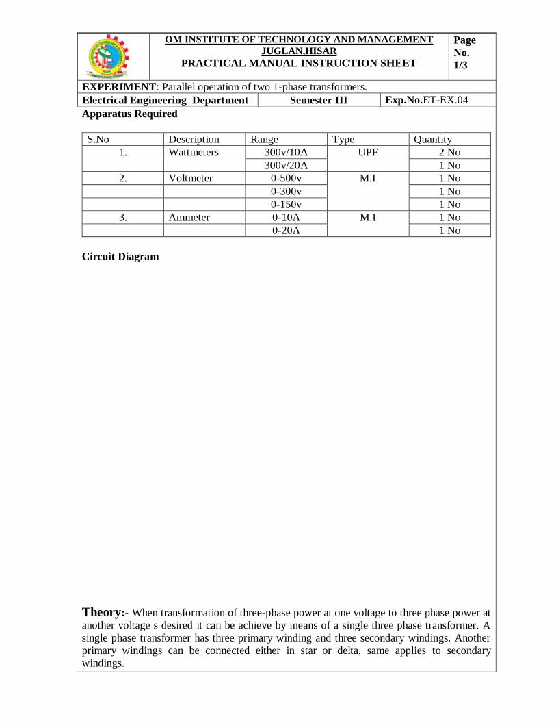
Theory:- When transformation of three-phase power at one voltage to three phase power at
another voltage s desired it can be achieve by means of a single three phase transformer. A
single phase transformer has three primary winding and three secondary windings. Another
primary windings can be connected either in star or delta, same applies to secondary
windings.
OM INSTITUTE OF TECHNOLOGY AND MANAGEMENT
JUGLAN,HISAR
PRACTICAL MANUAL INSTRUCTION SHEET
Page
No.
1/3
EXPERIMENT: Parallel operation of two 1-phase transformers.
Electrical Engineering Department Semester III Exp.No.ET-EX.04
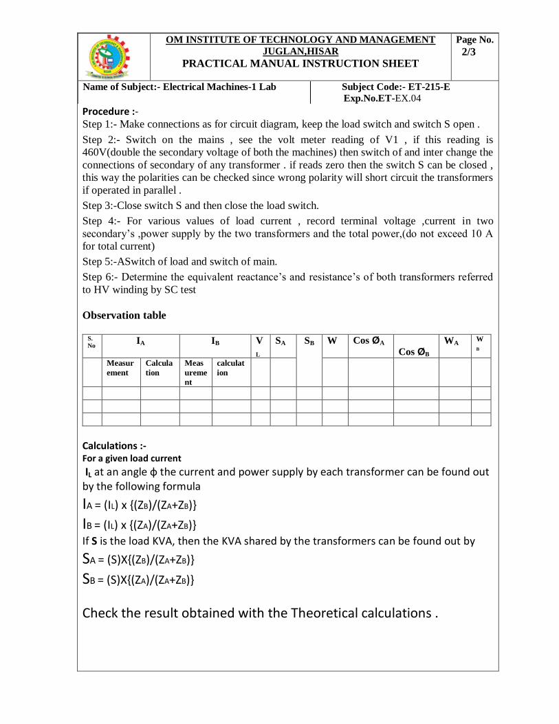
Procedure :- Step 1:- Make connections as for circuit diagram, keep the load switch and switch S open .
Step 2:- Switch on the mains , see the volt meter reading of V1 , if this reading is
460V(double the secondary voltage of both the machines) then switch of and inter change the
connections of secondary of any transformer . if reads zero then the switch S can be closed ,
this way the polarities can be checked since wrong polarity will short circuit the transformers
if operated in parallel .
Step 3:-Close switch S and then close the load switch.
Step 4:- For various values of load current , record terminal voltage ,current in two
secondary’s ,power supply by the two transformers and the total power,(do not exceed 10 A
for total current)
Step 5:-ASwitch of load and switch of main.
Step 6:- Determine the equivalent reactance’s and resistance’s of both transformers referred
to HV winding by SC test
Observation table
S.
No IA IB V
L
SA SB W Cos ØA Cos ØB
WA W
B
Measur
ement
Calcula
tion
Meas
ureme
nt
calculat
ion
Calculations :- For a given load current
IL at an angle ф the current and power supply by each transformer can be found out by the following formula
IA = (IL) x {(ZB)/(ZA+ZB)}
IB = (IL) x {(ZA)/(ZA+ZB)} If S is the load KVA, then the KVA shared by the transformers can be found out by
SA = (S)X{(ZB)/(ZA+ZB)}
SB = (S)X{(ZA)/(ZA+ZB)}
Check the result obtained with the Theoretical calculations .
OM INSTITUTE OF TECHNOLOGY AND MANAGEMENT
JUGLAN,HISAR
PRACTICAL MANUAL INSTRUCTION SHEET
Page No.
2/3
Name of Subject:- Electrical Machines-1 Lab Subject Code:- ET-215-E
Exp.No.ET-EX.04
Precautions:
3. 1. Auto Transformer whose variac should be in zero position, before switching on the ac supply.
4. 2.Transformer should be operated under rated values
Results:- a) With the help of phasor diagram verify if IA = IB= I.
b) Check if the load shared is proportional to the KVA capacities of the respective
transformers
c) From the results state if RA /XA =RB /XB
Viva-Voce
Q1) What is the material used for transformer core?
Q2) List the different losses in a transformer?
Q3) What is the condition of maximum efficiency?
OM INSTITUTE OF TECHNOLOGY AND MANAGEMENT
JUGLAN,HISAR
PRACTICAL MANUAL INSTRUCTION SHEET
Page No.
3/3
Name of Subject:- Electrical Machines-1 Lab Subject Code:- ET-215-E
Exp.No.ET-EX.04
Apparatus Required
S.No Description Range Type Qty
1 Auto Transformer 415V/0-470V,15A 3-phasewire wound 1 Nos
2 Ammeter 0-2A M.I 3 Nos
0-5A M.I 2 Nos
3 Voltmeter 0-150V M.I 2 Nos
0-250V M.I 1 No
4 Fuses 5A - 2 Nos
Load Box 230V/0-10A Rheostatic 1 Nos
Circuit Diagram
OM INSTITUTE OF TECHNOLOGY AND MANAGEMENT
JUGLAN,HISAR
PRACTICAL MANUAL INSTRUCTION SHEET
Page
No.
1/3
EXPERIMENT: To Convert three phase to two phase by Scott Connection
Electrical Engineering Department Semester III Exp.No.ET-EX.05
Theory: In some cases, we may require 2 powers instead of 3 or 1 power. For that it is
necessary to convert 3 to2 power (since 3 power is available at every nook corner). Scott
connection is one by which 3-phase to 2-phase transformation is accomplished with the help
of two identical 1 T/Fs having same current rating. One T/F has a center tap on primary side
and it is known as Main transformer. It forms the horizontal member of the connection.
Another T/F has 0.866tap on primary side and known as Teaser transformer. The 50% tap
point on primary side of the main T/F is joined to 86.6% tap on primary of the teaser T/F.
Obviously full rating of the T/Fs is not at all used. Refer to the fig. The main T/F primary
winding center tap point D is connected to one end of the primary of the teaser T/F on
secondary side, both the main & teaser T/F turns are used (not only 86.6%).Hence the
voltage per turn will be equal for both T/Fs. Since point D is located midway on AB, VCD
leads VAB by 900 i.e, voltages across primary are 900 apart also. Position of Neutral point N
on primary side: Remember point D is not the neutral on primary , since its voltages w.r.t R,
Y, B are not equal to V1/3 i.e, the neutral point is that one which gives equal voltage with R,
Y, B. The neutral point is one third the way down the teaser T/F winding from C to D Or
point N divides the teaser primary winding in the ratio of 1:2. Hence the neutral must be
At 86.6/3=28.8% from D
Current in Teaser T/F: w.r.t
For 2:1 T/F,
Current in Main T/F: N2 /0.866N1 = IR/IX
IR = InK(1.15) IR = 0.57xIX
N2/N1 = (IR/2 - IY/2)
For balanced load, since IX & IY are at 900
IR =⎣1200; IB =⎣-1200
Like wise, IR, IY & IB are equal in magnitude and are 1200 apart from each other.
Procedure Step No.1:-Give all connections as per the circuit diagram.
Step No.2:-Switch-ON the supply and apply rated voltage to the primaries.
Step No.3:- Note the voltmeters readings of both sec. Sides of both T/Fs.
Step No.4:-Now join the sec. in series aiding as shown in fig.and note he resultant voltage.
Step No.5:-Load both the T/Fs equally with out exceeding the rating and note the ammeter
readings on primary side.
Observations:
V4 (across sec. of teaser T/F) =
V5 (across sec. of main T/F) =
Resultant voltage, VT =V21+V22 =
OM INSTITUTE OF TECHNOLOGY AND MANAGEMENT
JUGLAN,HISAR
PRACTICAL MANUAL INSTRUCTION SHEET
Page No.
2/3
Name of Subject:- Electrical Machines-1 Lab Subject Code:- ET-215-E
Exp.No.ET-EX.05
Calculations:-
Load
Applied
A1 A2 A3 A4 A5
Precautions:- 1) The Dimmerstat should be kept at minimum O/P position initially.
2) The Dimmerstat should be varied slowly & uniformly.
3) Rated voltage should be applied to the primary of the Transformer.
Result:-
Viva Voce
Q1)Is the primary side balanced with a balanced load on secondary?
Ans) Yes, if the secondary is unbalanced, the primary also is unbalanced.
Q2) Is it possible to get a balanced three phase supply from a two phase supply?
Ans) Ues, Use a scott connection and feed its 2 phase side from 2 phase syupply and connect
the 3 phase load to the 3 phase side of the transformer.
Q3) In the scott connection are the two single phase transformer magnetically coupled?
Ans) The main transformer must not be magnetically coupled to the teaser transformer i.e
there are two are different units.
Q4) Name a method of 3 phase to 1 phase conversion and comment
Ans) Open delta connection enables 3 phase to 1 phase conversion.
OM INSTITUTE OF TECHNOLOGY AND MANAGEMENT
JUGLAN,HISAR
PRACTICAL MANUAL INSTRUCTION SHEET
Page No.
3/3
Name of Subject:- Electrical Machines-1 Lab Subject Code:- ET-215-E
Exp.No.ET-EX.05
Apparatus Required
S.No Description Range Type Qty
1 Voltmeter 0-300v DC M.C 1 No
0-10v DC M.C I No
2 Ammeter 0-2A M.C 1 No
0-5A M.C 1 No
3 Rheostat 2ohm,600A - 2 No
4 Tachometer - - 1 No
Circuit Diagram
Theory Load characteristics of the machine can be broadly classified into:- 1) External characteristics. 2) Internal Characteristics.
External Characteristics(V vs IL) It is a curve showing the variation in terminal voltage of the generator as the load on the generator is increased. The characteristics are as shown in the figure. At no load, the terminal voltage of the generator is at its rated value. As the load current is increased the terminal voltage drops. The drop in terminal voltage is due to the following reasons:- 1. For a generator V = Eg − IaRa, as the load current increases, Ia increases, IaRa drop increases, thus decreasing the terminal voltage V. 2. As the load current increases, Ia increases, armature reaction effect also increases. Due to demagnetizing effect of armature reaction, the induced emf Eg decreases, thereby
OM INSTITUTE OF TECHNOLOGY AND MANAGEMENT
JUGLAN,HISAR
PRACTICAL MANUAL INSTRUCTION SHEET
Page
No.
1/3
EXPERIMENT: To Perform Load test on DC shunt generator.
Electrical Engineering Department Semester III Exp.No.ET-EX.06
decreasing V. 3. Due to reasons (1) and (2), the terminal voltage decreases, which in turn reduces the field current Ish, thereby decreasing Eg causing further decrease in V.
Procedure Step 1:-Connections are made as shown in the diagram. Step 2:-Rheostat Rh1 is kept in minimum position and Rh2 in maximum position. Step 3:- Switch S2 is kept open. Supply is switched on and the motor is started using a 3-point starter. Step 3:-The motor field rheostat Rh1 is varied till the speed equals the rated speed of the motor. Step 4:-The generator field rheostat Rh2 is varied till the voltmeter reads the rated voltage of the machine. Step 5:- Switch S2 is then closed. Step 6:-The load on the generator is increased.The readings of the voltmeter and ammeters are noted down. Step 7:- The experiment is repeated for different values of load current till the rated current of the generator is reached. During the experiment, the speed is to be maintained constant at the rated value. Step 8:-The load is then switched off completely, the rheostats are brought back to the original position and the machine is switched off. Observation
S.No Volts(V) IL(A) Ish(A) Ia(A) Eg(V)
Sample Calculation (set no . . . )
Terminal Voltage (V) = . . . . . . . . …………. V Load Current (IL) = . . . . . ………………. . . .A Shunt Field Current (Ish) = . . . . . . . . ……...A Armature Current (IA) = IL + Ish = . . . . . . . . .A Generated emf (Eg) = V + IaRa = . . . . . . . . . Measurement of Armature Resistance
S.No Volts(V) I(A) Resistance(ohm)
Armature Resistance Ra = . . . . . . . . .ohm
OM INSTITUTE OF TECHNOLOGY AND MANAGEMENT
JUGLAN,HISAR
PRACTICAL MANUAL INSTRUCTION SHEET
Page No.
2/3
Name of Subject:- Electrical Machines-1 Lab Subject Code:- ET-215-E
Exp.No.ET-EX.06
Internal Characteristics [Eg vs Ia]
It is a plot of the internally generated emf (Eg) and armature current (Ia). It is a curve similar to the external characteristics and lies above it. Eg = V + IaRa
& Ia = IL + Ish Internal and External Characteristics
Machine Details
Result Conducted load test on the given DC shunt generator and plotted the external and internal
characteristics.
Viva Voce 1. What is the need for starter with a d.c motor? 2. How does a 3-point starter function? 3. Why is Rh1 kept in minimum position at starting? 4. Why is Rh2 kept in maximum position at starting? 5. Why does the terminal voltage of a generator decrease with increase in load? 6. How are the meter ratings selected for this experiment?
OM INSTITUTE OF TECHNOLOGY AND MANAGEMENT
JUGLAN,HISAR
PRACTICAL MANUAL INSTRUCTION SHEET
Page No.
3/3
Name of Subject:- Electrical Machines-1 Lab Subject Code:- ET-215-E
Exp.No.ET-EX.06
MOTOR GENERATOR
3.5 KW 3.5 KW
Speed - 1500rpm Speed - 1500rpm
volts - 220V volts - 220V
Amps - 18.6 A Amps - 16 A
Winding - shunt Winding – shunt
Apparatus Required
S.No Description Range Type Quantity
1 Voltmeter 0-300V MC 1 No
2 Ammeter 0-20A MC 1 No
3 Rheostat 300ohm/1.5A - 2 No
4 Tachometer 0-1500rpm Digital 1
5 Connecting Wires - - Required
Circuit Diagram
Theory
Speed(N) of a d.c shunt motor can be expressed as:-
N=(V-IaRa)/K Ø rpm. The motor when connected across constant voltage supply draws
constant field current. The flux (Ø) which is proportional to field current is thus constant.
When motor is loaded, armature current Ia increases with the increases in load causing an
increase in the armature drop IaRa . Generally, the armature resistance Ra is very small and
hence the drop Ia Ra is quite small compared to applied voltage GH,. This causes quite a
small drop in the speed on loading. If the speed of the shunt motor is plotted against armature
current, the characteristics will be obtained the toque developed is proportional to the product
of flux (Ø) and armature current Ia As Ø as constant.T prop Ø Ia
OM INSTITUTE OF TECHNOLOGY AND MANAGEMENT
JUGLAN,HISAR
PRACTICAL MANUAL INSTRUCTION SHEET
Page
No.
1/3
EXPERIMENT: To Perform Load test on DC shunt generator.
Electrical Engineering Department Semester III Exp.No.ET-EX.07
Procedure: Step 1:-Connections are made as per the circuit diagram Step 2:-After checking the no load condition, and minimum field rheostat position, DPST switch is
closed and starter resistance is gradually removed.
Step 3:- The motor is brought to its rated speed by adjusting the field rheostat.
Step 4. Ammeter, Voltmeter readings, speed and spring balance readings are noted under no load condition.
Step 5. The load is then added to the motor gradually and for each load, voltmeter, ammeter, spring
balance readings and speed of the motor are noted.
Step 6:- The motor is then brought to no load condition and field rheostat to minimum position, then
DPST switch is opened
Observation Table
S.No Voltage(V) Current
(A) Load Torque Speed(N)
rpm Input
Pi
Output
P0 watts Efficiency η %
S1 S2 T(Nm)
Calculation: Circumference of the Brake drum = ______ cm
Circumference
R= --------------------
2π
Torque:-( S1 to S2) x R x 9.81Nm
Input Power Pi = V×I Watts
Output Power= (2 π NT)/60
Efficiency η= output power/ Input Power
OM INSTITUTE OF TECHNOLOGY AND MANAGEMENT
JUGLAN,HISAR
PRACTICAL MANUAL INSTRUCTION SHEET
Page No.
2/3
Name of Subject:- Electrical Machines-1 Lab Subject Code:- ET-215-E
Exp.No.ET-EX.07
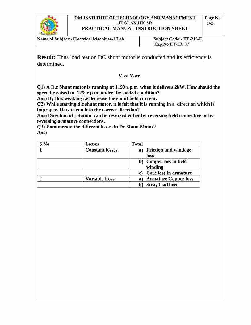
Result: Thus load test on DC shunt motor is conducted and its efficiency is
determined.
Viva Voce
Q1) A D.c Shunt motor is running at 1190 r.p.m when it delivers 2kW. How should the
speed be raised to 1259r.p.m. under the loaded condition?
Ans) By flux weaking i.e decrease the shunt field current.
Q2) While starting d.c shunt motor, it is felt that it is running in a direction which is
improper. How to run it in the correct direction?
Ans) Direction of rotation can be reversed either by reversing field connective or by
reversing armature connections.
Q3) Ennumerate the different losses in Dc Shunt Motor?
Ans)
S.No Losses Total
1 Constant losses a) Friction and windage
loss
b) Copper loss in field
winding
c) Core loss in armature
2 Variable Loss a) Armature Copper loss
b) Stray load loss
OM INSTITUTE OF TECHNOLOGY AND MANAGEMENT
JUGLAN,HISAR
PRACTICAL MANUAL INSTRUCTION SHEET
Page No.
3/3
Name of Subject:- Electrical Machines-1 Lab Subject Code:- ET-215-E
Exp.No.ET-EX.07
Apparatus Required
Theory: - It is a simple method in which losses are measured separately and from their
knowledge, efficiency at any load can be pre-determined in advance. The only running test
needed is a no load test. Swinburne’s test is applicable to those machines in which flux is
practically constant i.e. Shunt wound and Compound wound machines. The machine is
running as a motor on no-load at its rated voltage and its speed be adjusted to its rated value
using Shunt regulator. The no-load armature current is measured using an ammeter where as
shunt field current is given by another ammeter.
OM INSTITUTE OF TECHNOLOGY AND MANAGEMENT
JUGLAN,HISAR
PRACTICAL MANUAL INSTRUCTION SHEET
Page
No.
1/3
EXPERIMENT: Swinburne’s test of DC shunt Motor.
Electrical Engineering Department Semester III Exp.No.ET-EX.08
S.No. Description Range Type Quantity
1 Ammeter (0-20) A MC 1 No
2 Voltmeter (0-300) V MC 1 No
3 Rheostats 1250, 0.8A Wire
Wound
1 No
4 Tachometer (0-3000) rpm Digital 1 No
5 Resistive Load 5KW,230V - 1 No
6 Connecting Wires 2.5sq.mm. Copper Few
OM INSTITUTE OF TECHNOLOGY AND MANAGEMENT
JUGLAN,HISAR
PRACTICAL MANUAL INSTRUCTION SHEET
Page No.
4/4
Name of Subject:- Electrical Machines-1 Lab Subject Code:- ET-215-E
Exp.No.ET-EX.09
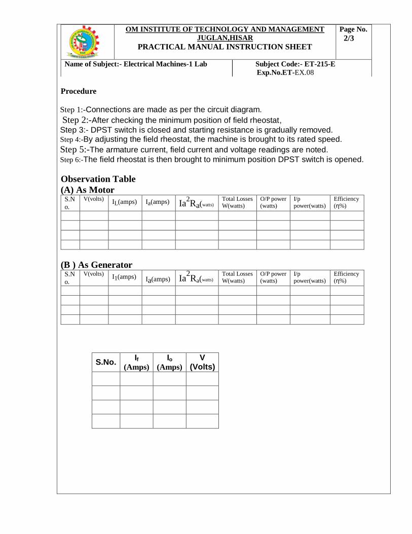
Procedure
1. Step 1:-Connections are made as per the circuit diagram.
2 Step 2:-After checking the minimum position of field rheostat,
Step 3:- DPST switch is closed and starting resistance is gradually removed. 3. Step 4:-By adjusting the field rheostat, the machine is brought to its rated speed.
4. Step 5:-The armature current, field current and voltage readings are noted.
5. Step 6:-The field rheostat is then brought to minimum position DPST switch is opened.
Observation Table
(A) As Motor S.N
o.
V(volts) IL(amps) Ia(amps) Ia2Ra(watts)
Total Losses W(watts)
O/P power (watts)
I/p power(watts)
Efficiency(η%)
(B ) As Generator S.N
o.
V(volts) I1(amps) Ia(amps) Ia2Ra(watts)
Total Losses W(watts)
O/P power (watts)
I/p power(watts)
Efficiency(η%)
S.No. If
(Amps)
Io
(Amps)
V (Volts)
OM INSTITUTE OF TECHNOLOGY AND MANAGEMENT
JUGLAN,HISAR
PRACTICAL MANUAL INSTRUCTION SHEET
Page No.
2/3
Name of Subject:- Electrical Machines-1 Lab Subject Code:- ET-215-E
Exp.No.ET-EX.08
DETERMINATION OF ARMATURE RESISTANCE:-
PROCEDURE:
Step 1. Connections are made as per the circuit diagram.
Step 2. Supply is given by closing the DPST switch.
Step 3. Readings of Ammeter and Voltmeter are noted.
Step 4. Armature resistance in Ohms is calculated as Ra = (Vx1.5) /I.
Observation Table for Armature resistance:
CALCULATIONS
Hot Resistance Ra = 1.2 X R Ω
Constant losses = VIo – Iao2 Ra watts
Where Iao = (Io – If) Amps
OM INSTITUTE OF TECHNOLOGY AND MANAGEMENT
JUGLAN,HISAR
PRACTICAL MANUAL INSTRUCTION SHEET
Page No.
3/4
Name of Subject:- Electrical Machines-1 Lab Subject Code:- ET-215-E
Exp.No.ET-EX.08
S.No. Voltage
V (Volts)
Current
I (Amps)
Armature Resistance
Ra (Ohms)
AS MOTOR:
Load Current IL = _____ Amps (Assume 15%, 25%, 50%, 75% of rated current)
Armature current Ia = IL – If Amps
Copper loss = Ia2 Ra watts
Total losses = Copper loss + Constant losses
Input Power = VIL watts
Output Power = Input Power – Total losses
Output power
Efficiency % = ---------------------- X 100%
Input Power
AS GENERATOR:
Load Current IL = _____ Amps (Assume 15%, 25%, 50%, 75% of rated current)
Armature current Ia = IL + If Amps
Copper loss = Ia2 Ra watts
Total losses = Copper loss + Constant losses
Output Power = VIL watts
Input Power = Input Power +Total losses
Output power
Efficiency % = ----------------------- X 100%
Input Power
PRECAUTIONS:
The field rheostat should be in the minimum position at the time of starting and stopping the motor RESULT:
Thus the efficiency of the D.C machine is predetermined by Swinburne’s test.
Viva Voce
Q) Explain the use of Swinburn’s Test?
OM INSTITUTE OF TECHNOLOGY AND MANAGEMENT
JUGLAN,HISAR
PRACTICAL MANUAL INSTRUCTION SHEET
Page No.
4/4
Name of Subject:- Electrical Machines-1 Lab Subject Code:- ET-215-E
Exp.No.ET-EX.08
Apparatus Required
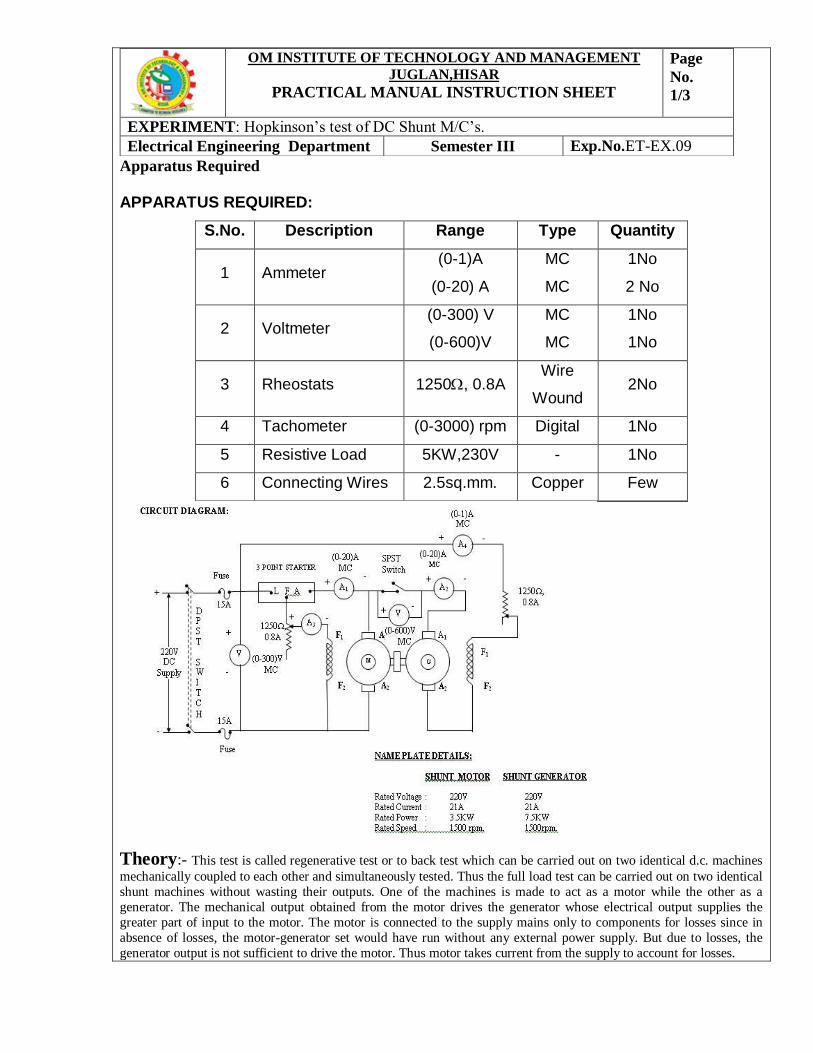
APPARATUS REQUIRED:
S.No. Description Range Type Quantity
1 Ammeter (0-1)A
(0-20) A
MC
MC
1No
2 No
2 Voltmeter (0-300) V
(0-600)V
MC
MC
1No
1No
3 Rheostats 1250, 0.8A Wire
Wound 2No
4 Tachometer (0-3000) rpm Digital 1No
5 Resistive Load 5KW,230V - 1No
6 Connecting Wires 2.5sq.mm. Copper Few
Theory:- This test is called regenerative test or to back test which can be carried out on two identical d.c. machines
mechanically coupled to each other and simultaneously tested. Thus the full load test can be carried out on two identical
shunt machines without wasting their outputs. One of the machines is made to act as a motor while the other as a
generator. The mechanical output obtained from the motor drives the generator whose electrical output supplies the
greater part of input to the motor. The motor is connected to the supply mains only to components for losses since in
absence of losses, the motor-generator set would have run without any external power supply. But due to losses, the
generator output is not sufficient to drive the motor. Thus motor takes current from the supply to account for losses.
OM INSTITUTE OF TECHNOLOGY AND MANAGEMENT
JUGLAN,HISAR
PRACTICAL MANUAL INSTRUCTION SHEET
Page
No.
1/3
EXPERIMENT: Hopkinson’s test of DC Shunt M/C’s.
Electrical Engineering Department Semester III Exp.No.ET-EX.09
PROCEDURE:
1. Step1 Connections are made as per the circuit diagram. 2. Step2 After checking the minimum position of field rheostat of motor, maximum
position of field rheostat of generator, opening of SPST switch, DPST switch is closed and starting resistance is gradually removed.
3. Step3 The motor is brought to its rated speed by adjusting the field rheostat of the motor.
4. Step4The voltmeter V1 is made to read zero by adjusting field rheostat of
generator and SPST switch is closed. 5. Step5 By adjusting field rheostats of motor and generator, various Ammeter
readings, voltmeter readings are noted. 6. Step6The rheostats and SPST switch are brought to their original positions and
DPST switch is opened.
Observation Table S.N
o
Suppl
y
volta
ge
V(Vo
lts)
I1(amps) I2(Amps) I3(Am
ps) I4(amps) I1+I2
Motor
Armatu
re cu
loss(W
atts)
Generat
or
Armatu
re Cu
Loss
W(Wat
ts)
Total
Stray
Loss
W(Wat
ts)
Stray Losses
per
M/C(watts)
As Motor
V I1(amp
s) I2(Amps) I3(A
mps)
Motor
Armature Cu
Loss W (
Weatts)
Field
Loss(watts)
Stray
Loss
I2(Am)
Total
Losses
Output
Power
(Watt)
Input
Power
(watt)
Efficien
η%
As Generator
V I1(amp
s) I2(Amps) Motor
Armature Cu
Loss W (
Weatts)
Field
Loss(watts)
Stray
Loss
I2(Am)
Total
Losses
Output
Power
(Watt)
Input
Power
(watt)
Efficien
η%
OM INSTITUTE OF TECHNOLOGY AND MANAGEMENT
JUGLAN,HISAR
PRACTICAL MANUAL INSTRUCTION SHEET
Page No.
2/3
Name of Subject:- Electrical Machines-1 Lab Subject Code:- ET-215-E
Exp.No.ET-EX.09
Procedure:
Step 1. Connections are made as per the circuit diagram.
Step 2. Supply is given by closing the DPST switch.
Step 3. Readings of Ammeter and Voltmeter are noted.
Step 4. Armature resistance in Ohms is calculated as Ra = (Vx1.5) /I.
Observation Table for Armature Resistance
Calculations:-
Input Power = VI1 watts
Motor armature cu loss = (I1+ I2)2 Ra watts
Generator armature cu loss = I22 Ra watts
Total Stray losses W = V I1 - (I1+I2)2 Ra + I2
2 Ra watts. Stray loss per machine = W/2 watts.
As motor:
Input Power = Armature input + Shunt field input = (I1+ I2) V + I3V = (I1+I2+I3) V
Total Losses = Armature Cu loss + Field loss + stray loss
= (I1 + I2)2 Ra + VI3 + W/2 watts
Input power – Total Losses
Efficiency % = ------------------------------------- x 100%
Input Power
As generator:
Output Power = VI2 watts
Total Losses = Armature Cu loss+ Field Loss + Stray loss
= I22 Ra + VI4 + W/2 watts
Output power
Efficiency % = -------------------------------------- x 100%
Output Power+ Total Losses
OM INSTITUTE OF TECHNOLOGY AND MANAGEMENT
JUGLAN,HISAR
PRACTICAL MANUAL INSTRUCTION SHEET
Page No.
3/4
Name of Subject:- Electrical Machines-1 Lab Subject Code:- ET-215-E
Exp.No.ET-EX.09
S.No. Voltage
V (Volts)
Current
I (Amps)
Armature Resistance
Ra (Ohms)
Sample Graph
Precautions:
The field rheostat of the motor should be in the minimum position at the time of starting and stopping the machine.
The field rheostat of the generator should be in the maximum position at the time of starting and stopping the machine.
SPST switch should be kept open at the time of starting and stopping the machine.
Result:
Thus Hopkinson’s test is conducted on a pair of identical DC machines the efficiency of the machine as generator and as motor are pre-determined
Viva Questions
Q) Will the iron losses be included in the calculations of Hopkinson’s Test?
Ans) Since the machines are operated at full load conditions, change in iron loss due to distortion in flux at
full load will be included in the calculation.
Q) What are the adverse situation happened at Hopkinson’s test
Ans) As the machines are tested under full load conditions, the temperature rise and quality of
communication of the two machines can be observed.
Q) Write a few disadvantage of Hopkinson’s Test?
Ans) 1.There is difficulty in availability of two identical machines.
2. The iron losses in the two machines can not be separated. The iron losses are different in both the
machines because of different excitations.
Q) Is the machine is suited for lower machines?
Ans) No, it is only suited for large machine.
Q) Which is the most difficult part of the hopkinson’s test
Ans) The machines are not loaded equally in case of small machines which may lead to difficulty in analysis.
OM INSTITUTE OF TECHNOLOGY AND MANAGEMENT
JUGLAN,HISAR
PRACTICAL MANUAL INSTRUCTION SHEET
Page No.
4/4
Name of Subject:- Electrical Machines-1 Lab Subject Code:- ET-215-E
Exp.No.ET-EX.09
Apparatus Required
S.No Description Range Type Qty
1 1 HP 3phase I.M - - 1 No.
2 1 HP DC Shunt Generator - - 1 No
3 1 HP DC Shunt Motor - - 1 No
4 3-phase 3 pole MCB - - 1 No
5 Star-Delta Starter - - 1 No.
6 DC MCB - - 1 No
7 Rheostat (0-220ohm)/2A - 1 No
8 Ammeter (0-2A) M.C 2 No
9 Voltmeter (0-300V) M.C 1 No
10 Fuse - - 5 No
Circuit Diagram
Theory:- This system is used where an unusally wide and very sensitive speed control is required as
for colliery winders,electric excavators,elevators and the main drives in steel mills and blooming and
paper mills. M.I is the main motor whose speed control is required. This field of this motor is perman
ently connected across the dc supply lines. By applying a variable voltage across its armature, any
desired speed can be obtained. This variable voltage is supplied by a motor-generator set which consis
ts of either a dc or an ac motor M2 directly coupled to generator G is directly fed to the main motor
M1. The voltage of the generator can be varied from zero up to its maximum value by means of its
Field regulator,By reversing the directon of the field current of G by means of the reversing switch Rs
Generated voltage can be reversed and hence the direction of rotation of M1. It should be remember
That motor generator set always runs in the same direction.
OM INSTITUTE OF TECHNOLOGY AND MANAGEMENT
JUGLAN,HISAR
PRACTICAL MANUAL INSTRUCTION SHEET
Page
No.
1/2
EXPERIMENT: Ward Leonard Method of Speed Control.
Electrical Engineering Department Semester III Exp.No.ET-EX.10
Procedure
Step 1 Connect the circuit as shown in circuit diagram.
Step 2 At base speed motor armature is fed at rated voltage.
Step 3 Field current is adjusted to the maximum value.
Step 4 For obtaining speeds below base speed armature voltage is reduced.
Step 5 For obtaining speeds above base speeds field is gradually weakened.
Observation Table
(A) Variation of speed below of base speed
S.No Armature Voltage(V) Speed(RPM)
(B) Variation of speed above base speed
S.No Field Current(A) Speed(RPM)
Calculation
Eb=V-IaRa=(ØZNP/60A)
N α 1/Ø, N α 1/Ra ( N is the rpm in speed)
Is flux per pole & Ra is armature resistance.
Precaution
1) All connections should be right.
2) Don’t touch live terminals.
3) Don’t insert the resistance in field winding, when motor begins to start.
4) Reading should be obtained carefully.
Result:- Draw Power vs speed and Torque vs speed characteristics.
Viva Voce
Q1) Explain power vs speed and torque vs speed characteristics for ward-leonard method?
Q2) In order to increase the speed above rated speed, which method of speed control is used in
DC shunt motor?
Q3) In order to decrease the speed below rated speed, which method of speed control is used in
DC shunt motor?
OM INSTITUTE OF TECHNOLOGY AND MANAGEMENT
JUGLAN,HISAR
PRACTICAL MANUAL INSTRUCTION SHEET
Page No.
2/2
Name of Subject:- Electrical Machines-1 Lab Subject Code:- ET-215-E