For Public Distribution 2012 VUSBC Code Cycle December 01, 2017* Electrical Plan Review Requirements Department of Planning & Development Review, Bureau of Permits and Inspections 900 East Broad Street, Room 110 Richmond, Virginia 23219 Office: (804) 646-4169 Fax: (804) 646-6948 PLANS ARE NOT REQUIRED FOR PROJECTS $5,000.00 OR LESS. **Plans, and/or other documents, may be required at the discretion of the inspector. ** (For any changes in the path of egress, the contractor shall comply with Section B-2.90) Plans are required to be submitted for all commercial projects and one and two family dwellings with photovoltaic (PV) systems within the city limits (EXCEPTIONS - exterior temporary power poles, projects $5,000 or less, and plenum area only low voltage). Single and two family dwelling projects are not required to submit plans. All project documents under a commercial electrical permit application shall be in PDF format and are required to be submitted (thumb/flash drive (preferred) or CD/DVD media) to the City of Richmond, City Hall, Room 110. For walk-in or mailed in permit applications or resubmissions, make sure to have a printed copy of either the permit application or plan intake sheet. **Do not leave Room 110 without your media (thumb/flash drive or CD/ DVD). The City will not claim responsibility for such devices.** Low voltage security (access or egress control systems or delayed locking or latching systems) and fire alarm shall be completed under separate permits. The following set of requirements are based on the 2012 version of the Virginia Uniform Statewide Building Code (VUSBC). This includes the 2012 editions of the Virginia Energy Conservation Code (VECC), Virginia Construction Code (VCC), and Virginia Rehabilitation Code (VRC). Other codes used for electrical plan review that are referenced by the VUSBC are the following: The requirements herein may not be required for all submissions. Please contact the Bureau of Permits and Inspections if you are unsure of which requirements are necessary for your project. Pages 24-25 (Annex D) of this checklist shall be submitted, as a PDF file, with all required Construction Documents as a check to make sure the engineer/owner/contractor has fulfilled the City’s requirements. The Checklist shall be signed by either the Contractor/Master Electrician OR Engineer. All appropriate items within this checklist that pertain to the project shall be checked (i.e. “X”), all other items shall be marked not applicable (i.e. “N/A”). *Changes to this document will occur on June 1st and December 1st (or when there is a code cycle change). Make sure to check the webpage on these dates for any revisions: http://www.richmondgov.com/planninganddevelopmentreview/forms.aspx For projects with approved/current permits, make sure all revised plans adhere to Section B-1.8 - B-1.14. International Building Code (IBC)-2012 ICC A117.1 Accessibility Standards - 2009 International Energy Conservation Code (IECC)-2012 NFPA 20-2010 ASME A17.1-2010 National Electrical Code (NEC)/(NFPA 70) - 2011 ASCE 7-10 NFPA 111-2010 ASCE 24-05 NFPA 110-2010 International Existing Building Code (IEBC)-2012
Transcript
For Public Distribution 2012 VUSBC Code Cycle December 01, 2017*
Electrical Plan Review Requirements
Department of Planning & Development Review, Bureau of Permits and Inspections
900 East Broad Street, Room 110
Richmond, Virginia 23219
Office: (804) 646-4169 Fax: (804) 646-6948
PLANS ARE NOT REQUIRED FOR PROJECTS $5,000.00 OR LESS. **Plans, and/or other documents, may be required at the discretion of the inspector. **
(For any changes in the path of egress, the contractor shall comply with Section B-2.90)
Plans are required to be submitted for all commercial projects and one and two family dwellings with photovoltaic
(PV) systems within the city limits (EXCEPTIONS - exterior temporary power poles, projects $5,000 or less, and
plenum area only low voltage). Single and two family dwelling projects are not required to submit plans.
All project documents under a commercial electrical permit application shall be in PDF format and are required
to be submitted (thumb/flash drive (preferred) or CD/DVD media) to the City of Richmond, City Hall, Room 110.
For walk-in or mailed in permit applications or resubmissions, make sure to have a printed copy of either the
permit application or plan intake sheet. **Do not leave Room 110 without your media (thumb/flash drive or CD/
DVD). The City will not claim responsibility for such devices.**
Low voltage security (access or egress control systems or delayed locking or latching systems) and fire
alarm shall be completed under separate permits.
The following set of requirements are based on the 2012 version of the Virginia Uniform Statewide Building Code
(VUSBC). This includes the 2012 editions of the Virginia Energy Conservation Code (VECC), Virginia
Construction Code (VCC), and Virginia Rehabilitation Code (VRC). Other codes used for electrical plan review
that are referenced by the VUSBC are the following:
The requirements herein may not be required for all submissions. Please contact the Bureau of Permits
and Inspections if you are unsure of which requirements are necessary for your project.
Pages 24-25 (Annex D) of this checklist shall be submitted, as a PDF file, with all required Construction
Documents as a check to make sure the engineer/owner/contractor has fulfilled the City’s requirements.
The Checklist shall be signed by either the Contractor/Master Electrician OR Engineer. All appropriate
items within this checklist that pertain to the project shall be checked (i.e. “X”), all other items shall be
marked not applicable (i.e. “N/A”).
*Changes to this document will occur on June 1st and December 1st (or when there is a code
cycle change). Make sure to check the webpage on these dates for any revisions:
Post-Permit Revised Construction Documents: [The “revision date” should be based on the revision date located on the plan(s). All plans in the set shall
have the same revision date]. For Post-Permit documents, do not use the “Plan Number” in the file name,
only the “Permit Number” (see below for a list of file descriptions that the City accepts):
DRAWING LEGEND:E1 LEGENDS AND ABBREVIATIONSE2 PART LIGHTING PLANE3 PART POWER PLANE3A LARGE SCALE DETAILE4 ONE-LINE DIAGRAME4A RISER DIAGRAME5 PANEL SCHEDULEE6 FIRE STOP DETAIL
1 HOUR FIRE RATED ASSEMBLY
2 HOUR FIRE RATED ASSEMBLY
3 HOUR FIRE RATED ASSEMBLY
DUPLEX RECEPTACLE – +18" A.F.F. UON
GFCI, WP DUPLEX RECEPTACLE - +18" A.F.F. UON
LIGHT SWITCH - +48" A.F.F. OR IN ELEV. PIT – 120V, 20A
TELEPHONE OR OUTLET - 4" SQUARE BOX WITH PLASTER RING AND 3/4”C. TO ABOVE CEILING
ABOVE FINISHED FLOORCOPPEREMPTY CONDUIT W/PULL STRINGEQUIPMENT GROUNDING CONDUCTORELEVATOREXISTINGGROUNDING ELECTRODE CONDUCTORGROUND FAULT INTERRUPTORGROUNDKILO-AMPERE INTERRUPT CURRENTKILO-VOLTKILO-VOLT-AMPERESMAIN CIRCUIT BREAKERMAIN LUGS ONLYMOUNTEDPHASE (AFTER NUMBER 1 OR 3) PRIMARYSECONDARYSWITCHBOARDUNLESS OTHERWISE NOTEDWIRE (AFTER NUMBER IN ONE-LINE),WATTSWITHWEATHERPROOFTRANSFORMERIMPEDANCE
CODE INFORMATION:2012 VIRGINIA STATEWIDE BUILDING CODE2011 NATIONAL ELECTRICAL CODE
1
1
Electrical Plan Requirements - December 01, 2017 Page 17
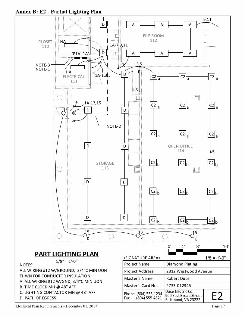
Annex B: E2 - Partial Lighting Plan
Project Name Diamond Plating
Project Address 2312 Westwood Avenue
Master’s Name Robert Duce
Master’s Card No. 2733-012345
E2
<SIGNATURE AREA>
C2 bC2 bC2 b
C2 bC2 bC2 b
C2 bC2 bC2 b
C2 aC2 aC2 a
C2 aC2 aC2 a
C2 aC2 aC2 a
DD
DD
DD
DD
D
D
D
K
15
K
13
K
15
K
13
A A A
A A A
1A-13,15
1A-1,3,5
HA
HA
‘P1A’‘1A’
NOTE-BNOTE-C
U6S
S
3,5
1A-7,9,11
9,11
OPEN OFFICE114
STORAGE113
FILE ROOM112
ELECTRICAL111
CLOSET110
S
5
NOTE-D
NOTES:ALL WIRING #12 W/GROUND, 3/4“C MIN UONTHWN FOR CONDUCTOR INSULATIONA. ALL WIRING #12 W/GND, 3/4“C MIN UON B. TIME CLOCK MH @ 48” AFFC. LIGHTING CONTACTOR MH @ 48" AFFD. PATH OF EGRESS
PART LIGHTING PLAN1/8“ = 1'-0”
0' 4' 8' 16'
1/8 = 1'-0"
Electrical Plan Requirements - December 01, 2017 Page 18
Project Name Diamond Plating
Project Address 2312 Westwood Avenue
Master’s Name Robert Duce
Master’s Card No. 2733-012345
E3
<SIGNATURE AREA>PART POWER PLAN
1/8“ = 1'-0”
0' 4' 8' 16'
1/8 = 1'-0"
NOTES:ALL WIRING #12 W/GROUND, 3/4“C MIN UONTHWN FOR CONDUCTOR INSULATIONA. 60A, 3PHASE NON-FUSED DISCONNECT SWITCHB. EQUIPMENT WORKING CLEARANCE 30”x36"
‘P1A’‘1A’
28,30
1A-19,21,23
OPEN OFFICE114
STORAGE113
FILE ROOM112
ELECTRICAL111
CLOSET110
C
WPGFI
WPGFI
23
21
1
1A-14,16,18
60/3-N.F.NEMA 1
EX. FAN
1A-8,10,12
3/4“C. - 3#10, 1#10G.
1A-20,22,24
30
HP-6
1A-2,4,61"C. 3#8, 1#8G.
22,24
24
NOTE-A
1A-26,28,30
LOCATED ON ROOF NOTE-B
NOTE-B
2
2
2
Annex B: E3 - Partial Power Plan
Electrical Plan Requirements - December 01, 2017 Page 19
Annex B: E4 - One-Line Diagram
ME
PM
LOD
PU
MLO
P1
AM
LO
L1A
20
0AM
CB
(EX
IST
) U
TILI
TY
PA
D M
T’D
XFM
R1
500
KV
A, 2
% Z
, 13
.2K
V P
RI
48
0/2
77V
, 3P
H, 4
W S
EC
(EX
IST
) U
TILI
TY
UN
DE
RG
RO
UN
DSE
RV
ICE
LATE
RA
L C
ON
DU
CTO
RS
(EX
IST
) SW
BD
‘SH
’2
500
A, 4
80V
, 3P
H,
4W
, 10
0KA
IC
W/2
000
A/3
P M
CB
(EX
IST
) 3
/0 C
U G
EC
TO
CO
LD W
AT
ER M
AIN
(EX
IST
) SW
BD
-2, 2
SE
TS3
"C. W
/ 4
#3
50k
cmil,
#1
EG
C
(EX
IST
) SW
BD
-1, 2
SE
TS3
1/2
“C. W
/ 4
#6
00k
cmil,
#1
/0 E
GC
(EX
IST
) SW
BD
-33
1/2
“C. W
/ 4
#5
00k
cmil,
1#
3 E
GC
(NEW
) SW
BD
-41
1/4
“C. W
/ 4
#2
, 1#
8 E
GC
(NEW
) FL
OO
R M
T’D
XFM
R7
5K
VA
, 6%
Z, 4
80V
, 3P
H P
RI
20
8Y/1
20V
, 3P
H, 4
W S
EC
1#
4 C
U T
O C
OLD
WA
TER
PIP
E
(NEW
) SW
BD
-4 2
1/2
“C. W
/ 4
#4
/0, 1
#4
EG
CFA
ULT
= 3
,13
0A
E4
CIR
CU
IT B
REA
KE
R
TRA
NSF
OR
ME
R
PA
NEL
(M
CB
/MLO
)
EAR
TH G
RO
UN
D
SY
MB
OL
S L
EG
EN
D
ON
E-LI
NE
DIA
GR
AM
NO
T T
O S
CA
LE
ALL
NE
W W
IRIN
G S
HA
LL B
E W
ITH
TH
HN
/TH
WN
INSU
LATI
ON
.
1 P
roje
ct N
ame
Dia
mo
nd
Pla
tin
g
Pro
ject
Ad
dre
ss2
312
Wes
two
od
Ave
nu
e
Mas
ter’
s N
ame
Ro
be
rt D
uce
Mas
ter’
s C
ard
No
.2
733
-01
234
5
<SI
GN
AT
UR
E A
RE
A>
1
1
Electrical Plan Requirements - December 01, 2017 Page 20
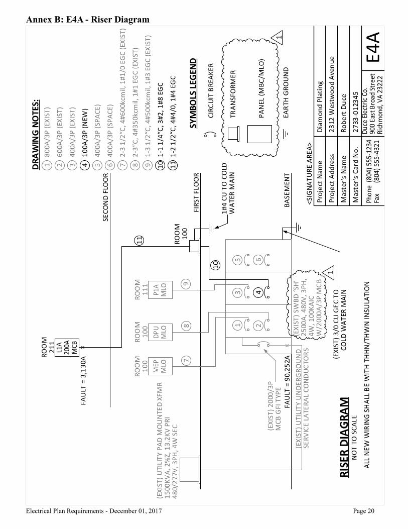
Annex B: E4A - Riser Diagram
E4A
CIR
CU
IT B
REA
KE
R
TRA
NSF
OR
ME
R
PA
NEL
(M
BC
/MLO
)
EAR
TH G
RO
UN
D
SYM
BO
LS L
EGEN
D
RIS
ER
DIA
GR
AM
NO
T T
O S
CA
LE
ALL
NE
W W
IRIN
G S
HA
LL B
E W
ITH
TH
HN
/TH
WN
INSU
LATI
ON
FAU
LT =
90
,25
2A
(EX
IST
) 2
000
/3P
MC
B G
FI T
YPE
BA
SEM
ENT
(EX
IST
) U
TILI
TY
UN
DE
RG
RO
UN
DSE
RV
ICE
LATE
RA
L C
ON
DU
CTO
RS
(EX
IST
) U
TILI
TY
PA
D M
OU
NTE
D X
FMR
15
00K
VA
, 2%
Z, 1
3.2
KV
PR
I4
80/
27
7V, 3
PH
, 4W
SE
C
FIR
ST F
LOO
R
SEC
ON
D F
LOO
R
DR
AW
ING
NO
TES:
80
0A/3
P (
EXIS
T)
60
0A/3
P (
EXIS
T)
40
0A/3
P (
EXIS
T)
10
0A/3
P (
NEW
)
40
0A/3
P (
SPA
CE
)
40
0A/3
P (
SPA
CE
)
2-3
1/2
“C, 4
#6
00k
cmil,
1#
1/0
EG
C (
EXIS
T)
2-3
”C, 4
#3
50k
cmil,
1#
1 E
GC
(EX
IST
)
1-3
1/2
“C, 4
#5
00k
cmil,
1#
3 E
GC
(EX
IST
)
1-1
1/4
“C, 3
#2
, 1#
8 E
GC
1-2
1/2
“C, 4
#4
/0, 1
#4
EG
C
(EX
IST
) 3
/0 C
U G
EC
TO
CO
LD W
AT
ER M
AIN
RO
OM
10
0R
OO
M1
00
RO
OM
11
1
1#
4 C
U T
O C
OLD
W
ATE
R M
AIN
RO
OM
21
1
FAU
LT =
3,1
30A
RO
OM
10
0
Pro
ject
Nam
eD
iam
on
d P
lati
ng
Pro
ject
Ad
dre
ss2
312
Wes
two
od
Ave
nu
e
Mas
ter’
s N
ame
Ro
be
rt D
uce
Mas
ter’
s C
ard
No
.2
733
-01
234
5
<SI
GN
AT
UR
E A
RE
A>
11
10987654321
98
7
11
10 65
43
21
1
(EX
IST
) SW
BD
‘SH
’2
500
A, 4
80V
, 3P
H,
4W
, 10
0KA
IC
W/2
000
A/3
P M
CB
1
Electrical Plan Requirements - December 01, 2017 Page 21
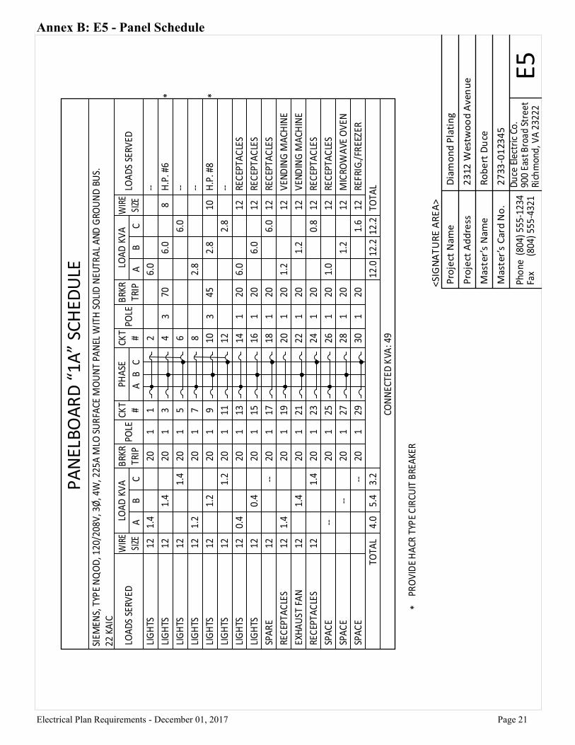
Annex B: E5 - Panel Schedule
E5
PA
NEL
BO
AR
D “
1A”
SCH
EDU
LE
Pro
ject
Nam
eD
iam
on
d P
lati
ng
Pro
ject
Ad
dre
ss2
312
Wes
two
od
Ave
nu
e
Mas
ter’
s N
ame
Ro
be
rt D
uce
Mas
ter’
s C
ard
No
.2
733
-01
234
5
<SI
GN
AT
UR
E A
RE
A>
Electrical Plan Requirements - December 01, 2017 Page 22
Annex B: E6 - UL Rated Fire Stop Detail
E6
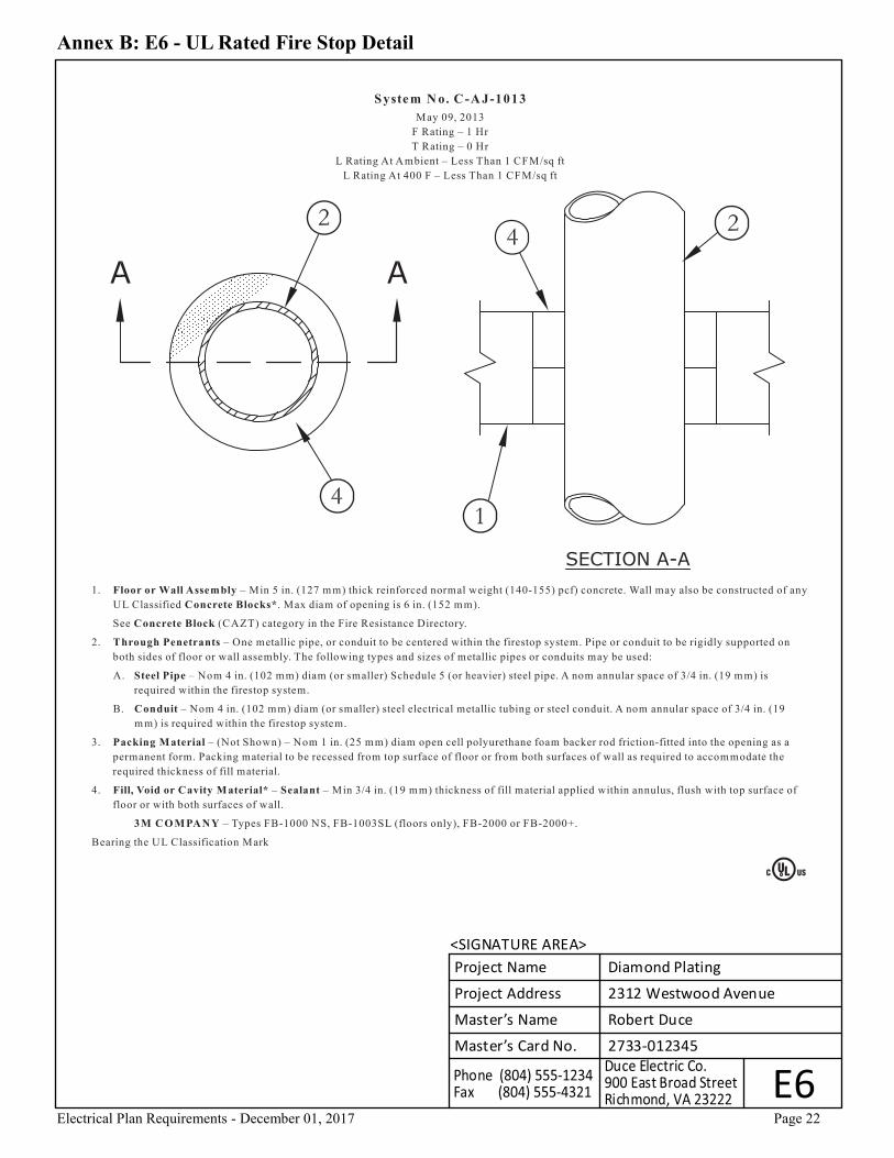
System N o. C -A J-1013
May 09, 2013
F Rating – 1 Hr
T Rating – 0 Hr
L Rating At Ambient – Less Than 1 CFM/sq ft
L Rating At 400 F – Less Than 1 CFM/sq ft
1. Floor or Wall Assembly – Min 5 in. (127 mm) thick reinforced normal weight (140-155) pcf) concrete. Wall may also be constructed of any
UL Classified Concrete Blocks*. Max diam of opening is 6 in. (152 mm).
See Concrete Block (CAZT) category in the Fire Resistance Directory.
2. Through Penetrants – One metallic pipe, or conduit to be centered within the firestop system. Pipe or conduit to be rigidly supported on
both sides of floor or wall assembly. The following types and sizes of metallic pipes or conduits may be used:
A. Steel Pipe – Nom 4 in. (102 mm) diam (or smaller) Schedule 5 (or heavier) steel pipe. A nom annular space of 3/4 in. (19 m m) is
required within the firestop system.
B. Conduit – Nom 4 in. (102 mm) diam (or smaller) steel electrical metallic tubing or steel conduit. A nom annular space of 3/4 in. (19
m m) is required within the firestop system.
3. Packing Material – (Not Shown) – Nom 1 in. (25 m m) diam open cell polyurethane foam backer rod friction-fitted into the opening as a
permanent form. Packing material to be recessed from top surface of floor or from both surfaces of wall as required to accom modate the
required thickness of fill material.
4. Fill, Void or Cavity Material* – Sealant – Min 3/4 in. (19 mm) thickness of fill material applied within annulus, flush with top surface of
floor or with both surfaces of wall.
3M CO M PANY – Types FB-1000 NS, FB-1003SL (floors only), FB-2000 or FB-2000+.
Bearing the UL Classification Mark
Project Name Diamond Plating
Project Address 2312 Westwood Avenue
Master’s Name Robert Duce
Master’s Card No. 2733-012345
<SIGNATURE AREA>
Electrical Plan Requirements - December 01, 2017 Page 23
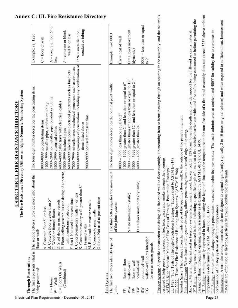
Annex C: UL Fire Resistance Directory U
SIN
G T
HE
UL
FIR
E R
ES
IST
AN
CE
DIR
EC
TO
RY
T
he
Fir
e R
esis
tan
ce D
irec
tory
Uti
lize
s a
n A
lph
a-N
um
eric
Nu
mb
erin
g S
yst
em
T
hro
ugh
Pen
etra
tio
ns
The
firs
t re
pre
sents
wh
at i
s
bei
ng p
enet
rate
d:
F =
Flo
ors
W =
Wal
ls
C =
Flo
ors
Or
Wal
ls
(C
om
bin
ed)
The
seco
nd
let
ter(
s) p
rovid
e m
ore
info
ab
out
the
flo
or
or
wal
l:
A.
Co
ncr
ete
flo
or
5”
or
less
B.
Co
ncr
ete
flo
or
gre
ater
than
5”
C.
Wo
od
or
fram
ed f
loo
rs
D.
Ste
el d
ecks
in m
arin
e vess
els
E.
Flo
or-
ceil
ing a
ssem
bli
es c
onsi
stin
g o
f co
ncr
ete
wit
h m
em
bra
ne
pro
tect
ion
F t
hru
i.
No
t use
d a
t p
rese
nt
tim
e
J. C
oncr
ete/
mas
onry
wal
ls 8
” o
r le
ss
K.
Co
ncr
ete/
mas
onry
wal
l gre
ater
than
8”
L.
Fra
med
wal
ls
M.
Bulk
hea
ds
in m
arin
e ves
sels
N.
Co
mp
osi
te p
anel
wal
ls
O t
hru
z.
No
t u
sed
at
pre
sent
tim
e
The
four
dig
it n
um
ber
des
crib
es t
he
pen
etra
tin
g i
tem
:
00
00
-099
9 n
o p
enet
rati
ng i
tem
s
10
00
-199
9 m
etal
lic
pip
e, c
ond
uit
or
tub
ing
20
00
-299
9 n
on
met
alli
c p
ipe,
co
nd
uit
or
tub
ing
30
00
-399
9 e
lect
rica
l ca
ble
s
40
00
-499
9 c
able
tra
ys
wit
h e
lect
rica
l ca
ble
s
50
00
-599
9 i
nsu
late
d p
ipes
60
00
-699
9 m
isce
llan
eous
elec
tric
al p
enet
rants
such a
s b
usd
uct
s
70
00
-799
9 m
isce
llan
eous
mec
han
ical
pen
etra
nts
such a
s ai
r d
uct
s
80
00
-899
9 g
roup
ings
of
pen
etra
tio
ns
inclu
din
g a
ny c
om
bin
ati
on o
f
item
s li
sted
ab
ove
90
00
-999
9 n
ot
use
d a
t p
rese
nt
tim
e
Exam
ple
: ca
j 1
22
6
C =
flo
or
or
wal
l
A =
co
ncr
ete
flo
or
5”
or
less
J =
co
ncr
ete
or
blo
ck
wal
l 8
” o
r le
ss
12
26
= m
etal
lic
pip
e,
cond
uit
or
tub
ing
Jo
int
syte
ms
The
firs
t tw
o l
ett
ers
iden
tify
ty
pe
of
join
t:
FF
fl
oo
r-to
-flo
or
WW
w
all-
to-w
all
FW
fl
oo
r-to
-wal
l
HW
hea
d-o
f-w
all
BW
b
ott
om
-of-
wal
l
CG
w
all-
to-w
all
join
ts i
nte
nd
ed
for
use
as
corn
er g
uar
ds
The
thir
d l
ette
r si
gnif
ies
the
mo
vem
ent
of
the
join
t sy
stem
:
S =
no
mo
vem
ent
(sta
tic)
D =
all
ow
s m
ovem
ent
(dynam
ic)
The
four
dig
it n
um
er d
escr
ibes
the
no
min
al j
oin
t w
idth
:
00
00
– 0
99
9 l
ess
than
or
equal
to
2”
10
00
– 1
99
9 g
reat
er t
han
2”
and
les
s th
an o
r eq
ual
to
6”
20
00
– 2
99
9 g
reat
er t
han
s 6
” an
d l
ess
than o
r eq
ual
to
12
”
30
00
– 3
99
9 g
reat
er t
han
12
” an
d l
ess
than
or
equal
to
24
”
40
00
– 4
99
9 g
reat
er t
han
24
”
Exam
ple
: h
wd
00
03
Hw
= h
eat
of
wal
l
D =
all
ow
s m
ovem
ent
(dynam
ic)
00
03
= l
ess
than o
r eq
ual
to 2
”
Fir
esto
p s
yst
em:
A s
pec
ific
co
nst
ruct
ion c
on
sist
ing o
f a
fire
-rat
ed w
all
or
flo
or
asse
mb
ly,
a p
enet
rati
ng i
tem
or
item
s p
assi
ng t
hro
ug
h a
n o
pen
ing i
n t
he
asse
mb
ly,
and
the
mate
rial
s
des
igned
to
hel
p p
reven
t th
e sp
read
of
fire
, to
xic
gas
es a
nd
sm
oke
thro
ugh t
he
op
enin
gs.
AS
TM
E-8
14
: “S
tand
ard
Met
ho
d o
f F
ire
Tes
ts o
f T
hro
ugh
-Pen
etra
tio
n F
ires
top
s.”
UL
14
29
: “F
ire
Tes
ts o
f T
hro
ug
h-P
enet
rati
on F
ires
top
s.”
(Eq
uiv
alent
to A
ST
M E
-81
4)
UL
20
79
: “T
ests
fo
r F
ire
Res
ista
nce
of
Buil
din
g J
oin
t S
yst
ems.
” (A
ST
M E
19
66)
An
nula
r S
pac
e: T
he
dis
tance
fro
m t
he
insi
de
edge
of
the
op
enin
g (
flo
or/
wal
l) t
o t
he
outs
ide o
f th
e p
enet
rati
ng i
tem
.
Po
int
of
Conta
ct:
When
lis
ted
on U
L s
yst
em d
raw
ing,
allo
ws
pen
etra
tin
g i
tem
to
“to
uch
’ ed
ge
of
op
enin
g.
Bac
kin
g M
ater
ial:
Mat
eria
l use
d i
n F
ires
top
syst
ems
(e.g
. m
iner
al w
oo
l, b
acker
ro
d,
CF
12
8 f
oam
) to
set
the
dep
th a
nd
pro
vid
e su
pp
ort
fo
r th
e fi
ll/v
oid
or
cavit
y m
ater
ial.
“F”
Rat
ing
: A
rat
ing u
suall
y e
xp
ress
ed i
n h
ours
ind
icat
ing a
sp
ecif
ic l
eng
th o
f ti
me
that
a f
ire-r
esis
tive
bar
rier
can
wit
hst
and
fir
e b
efo
re b
eing c
onsu
med
or
bef
ore
per
mit
tin
g t
he
pas
sage
of
flam
e th
roug
h a
n o
pen
ing i
n t
he
asse
mb
ly a
s d
eterm
ined
by A
ST
M E
-81
5 a
nd
UL
14
79
.
“T”
Rat
ing:
A r
atin
g u
sual
ly e
xp
ress
ed i
n h
ours
ind
icat
ing t
he
length
of
tim
e th
at t
he
tem
pera
ture
on t
he
no
n-f
ire
side
of
a f
ire-
rate
d a
ssem
bly
do
es n
ot
exce
ed 3
25
F a
bo
ve
amb
ien
t
tem
per
ature
as
det
erm
ined
by A
ST
M E
-84
and
UL
14
79
.
“L”
Rat
ing:
Am
ou
nt
of
air
leakag
e th
rou
gh a
pen
etr
atio
n,
meas
ure
d i
n c
ub
ic f
eet
per
min
ute
. T
he
test
is
adm
inis
tere
d a
t am
bie
nt
and
40
0'F
fo
r val
idit
y d
ue
to v
aria
nce
s in
per
form
ance
of
fire
sto
p s
yst
ems
at d
iffe
rent
tem
per
ature
s.
Intu
mes
cent:
A t
erm
des
crib
ing m
ater
ials
wh
ich a
re d
esig
ned
to
exp
and
sig
nif
ican
tly (
typ
ical
ly 2
to
10
tim
es
ori
gin
al v
olu
me)
and
when e
xp
ose
d t
o s
uff
icie
nt
hea
t. I
ntu
mesc
ent
mat
eria
ls a
re o
ften
use
d a
s fi
rest
op
s, p
arti
cula
rly a
rou
nd
co
mb
ust
ible
pen
etra
nts
.
Electrical Plan Requirements - December 01, 2016 Page 24
Electrical Plan Requirements - December 01, 2016 Electrical Plan Requirements - June 01, 2017 Electrical Plan Requirements - December 01, 2017
Section A-01
Note
Provide a complete set of electronic (PDF) electrical Construction Documents on either a thumb drive or CD/DVD. For plans, make sure you have one PDF file of all plans. All submitted documents shall follow the naming convention in Section A-5, page 5.
Section A-02
Note
Plans shall be neat and legible, and shall be all the same size. See Annex B for example plans.
Section A-03
Note
Plans shall be at least 1/8" (1/8” = 1’-0”) scale or larger, other than site plans. Provide a graphical scale(s) on all plans that have scaled floorplans. Provide a graphical scale for all different scaled floorplans on each plan (see Annex B-E2, E3 and E3A for examples).
Section A-04
Note
For project with more than one plan/sheet/plan, provide a list of all plans, on the first electrical plan, stating sheet number and description of the plan. See Annex B-E1 for an example.
Section A-05
Note
All rooms/areas containing new/relocated equipment (service entrance equipment, electrical panels, transformers, etc.) are required to show all working clearance space about equipment. See Annex B-E3 for an example. Show all new and existing equipment and any other obstructions (trees, walls, etc.) in these rooms/areas. Make sure this is a plan view, not an elevation view (elevation view is optional unless it is required to show equipment location(s)).
Section A-06
Note
All text on the plans shall be at least 0.125" in height. Exceptions: Photometrics, superscripts, and subscripts at least 0.1” in height.
Section A-07
Note
All plans shall have the information shown in the example title block in Section A-1. See Annex B-E1 for an example.
Section A-08
Note
On the first electrical plan, provide all the project information shown in Section A-2. See Annex B-E1 for an example.
Section A-09
Note
Provide all necessary engineering details on the plan(s).
Section A-10
Note
Provide a legend for all symbols and abbreviations/acronyms on the plan(s). See Annex B-E1 for an example.
Section A-11
Note
For projects that require specifications, provide the only the electrical specifications on the plans, or submit a hardcopy along with the plans. For hardcopy specifications, provide an electronic (PDF) copy of the specifications. Follow the naming convention in Section A-5, page 5.
Section A-12
Note
Within the scope of work, all spaces (specify dwelling unit numbers) and rooms shall be labeled, on all the plan(s), as to their use. See Annex B-E2, E3 for an example. This includes spaces such as closets, hallways, etc.
Section A-13
Note
All Plans shall be signed by the proper individual. See Annex A for a list of all Use Groups and whom can sign these plans. List is based on the Code of Virginia §54.1-402. Only one signature or signed/seal shall be on each plan.
Section A-14
Note
New work shall be differentiated from that which exists. See Section B-1 for more information. See Annex B-E4, E4A for an example. The plans shall make it clear what is new and what is existing.
Section A-15
Note
Electrical site work requires plans. All parking lots with lighting shall be routed to Zoning for review. Provide graphical scale on all site plan plans (see Annex B-E2, E3 for an example).
Section A-16
Note
For multi-level buildings, there shall be a floor plan for each and every level, do not show a “typical” floor plan for multiple levels. The electrical inspector will use this for their inspections.
Section A-17
Note
For all projects (other than Residential Buildings per VECC) with any new lighting, provide a COMCheck. Depending on project, provide the Interior and/or Exterior Lighting COMCheck, in PDF format. Make sure fixture designations (i.e. fixture type “A”, “B”, etc.) shown in the fixture schedule (fixtures designation shall be shown for all fixtures on the plans) are shown in the COMCheck as well. Provide this on the plan(s), or submit an electronic (PDF) copy of the Interior and/or Exterior COMCheck(s). COMCheck(s) shall be signed by the proper individual based on Section A.13. Follow the naming convention in Section A-5, page 5. See Section A-4 for a URL link to the COMCheck software.
Section A-18
Note
For dwelling units in multi-use building(s) or use groups R2, and R4 with greater than three stories, state on the plan(s) how the project is in compliance with IECC C405.1, exception. Provide on the plan(s), the percentage of high-efficacy fixtures for each dwelling unit and provide the lumens/watt rating in the fixture schedule.
Section A-19
Note
For project with new or revised load(s), provide load calculations for entire normal service [provide separate load calculation for new generator(s)] on the plan(s). For renovation projects, provide existing load based on Article 220.87. Refer to NEC 220, NEC ANNEX D
Section A-20
Note
For high-rise buildings, provide all necessary emergency and legally required loads as specified for high-rise buildings on the plan(s). Refer to IBC Section 403.
Section A-21
Note
For projects with hazardous areas, show this on the plan(s) stating the Class and Division as well. Show an outline of each hazardous area on the plans. Refer to NEC Article 500.
Section A-22
Note
For all patient care projects, provide a list on the plan(s) stating which rooms/areas are patient care areas. Provide proper wiring to these locations. Refer to NEC Article 517.
Section A-23
Note
For projects with photovoltaic, see Section D-2 for the City of Richmond’s plan requirements for photovoltaic projects. Refer to NEC Article 690.
Section A-24
Note
For projects that require selective coordination, refer to Section D-1 for the City of Richmond’s requirements for Coordination Studies.
Section A-25
Note
For all projects listed as class IV in Chapter 16 of the VCC (Table 1604.5), provide seismic details for mounting of all emergency equipment and devices. Refer to Section D-3 for Seismic Requirements.
Section B-1.01
Note
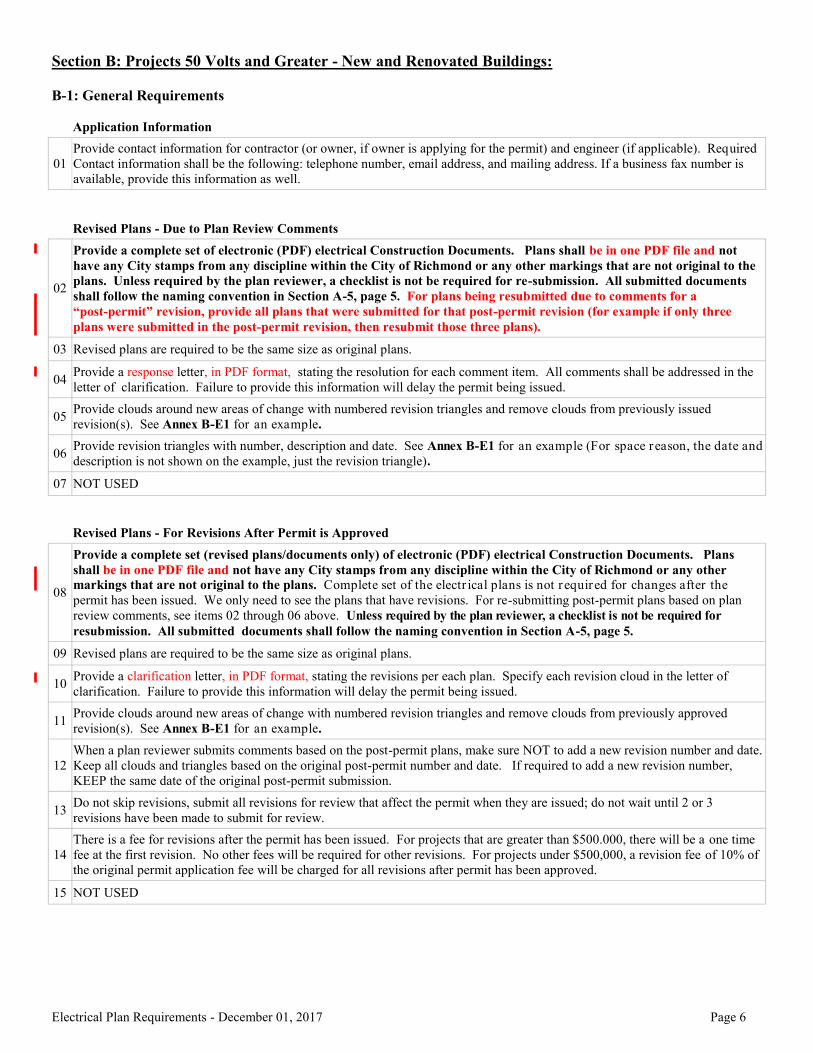
Provide contact information for contractor (or owner, if owner is applying for the permit) and engineer (if applicable). Required Contact information shall be the following: telephone number, email address, and mailing address. If a business fax number is available, provide this information as well.
Section B-1.03
Note
Revised plans are required to be the same size as original plans.
Section B-1.04
Note
Provide a response letter, in PDF format, stating the resolution for each comment item. All comments shall be addressed in the letter of clarification. Failure to provide this information will delay the permit being issued.
Section B-1.05
Note
Provide clouds around new areas of change with numbered revision triangles and remove clouds from previously issued revision(s).
Section B-1.06
Note
Provide revision triangles with number, description and date.
Section B-1.07
Note
NOT USED
Section B-1.08
Note
Provide a complete set (revised plans/documents only) of electronic (PDF) electrical Construction Documents. Plans shall be in one PDF file and not have any City stamps from any discipline within the City of Richmond or any other markings that are not original to the plans. Complete set of the electrical plans is not required for changes after the permit has been issued. We only need to see the plans that have revisions. For re-submitting post-permit plans based on plan review comments, see items 02 through 06 above. Unless required by the plan reviewer, a checklist is not be required for resubmission. All submitted documents shall follow the naming convention in Section A-5, page 5.
Section B-1.09
Note
Revised plans are required to be the same size as original plans.
Section B-1.10
Note
Provide a clarification letter, in PDF format, stating the revisions per each plan. Specify each revision cloud in the letter of clarification. Failure to provide this information will delay the permit being issued.
Section B-1.02
Note
Provide a complete set of electronic (PDF) electrical Construction Documents. Plans shall be in one PDF file and not have any City stamps from any discipline within the City of Richmond or any other markings that are not original to the plans. Unless required by the plan reviewer, a checklist is not be required for re-submission. All submitted documents shall follow the naming convention in Section A-5, page 5. For plans being resubmitted due to comments for a “post-permit” revision, provide all plans that were submitted for that post-permit revision (for example if only three plans were submitted in the post-permit revision, then resubmit those three plans).
Section B-1.11
Note
Provide clouds around new areas of change with numbered revision triangles and remove clouds from previously approved revision(s). See Annex B-E1 for an example.
Section B-1.12
Note
When a plan reviewer submits comments based on the post-permit plans, make sure NOT to add a new revision number and date. Keep all clouds and triangles based on the original post-permit number and date. If required to add a new revision number, KEEP the same date of the original post-permit submission.
Section B-1.13
Note
Do not skip revisions, submit all revisions for review that affect the permit when they are issued; do not wait until 2 or 3 revisions have been made to submit for review.
Section B-1.14
Note
There is a fee for revisions after the permit has been issued. For projects that are greater than $500.000, there will be a one time fee at the first revision. No other fees will be required for other revisions. For projects under $500,000, a revision fee of 10% of the original permit application fee will be charged for all revisions after permit has been approved.
Section B-1.15
Note
NOT USED
Section B-2.01
Note
If there are no rated assemblies or no rated assemblies being penetrated, state this on the plans. Clearly label all fire rated assemblies, firewalls, fire separation walls as to their rating in hours on all electrical plans. See Annex B-E2, E3. [VCC 714.3.2]
Section B-2.02
Note
Provide, on the plan(s), UL listed fire stopping detail as found in the latest edition of the UL Fire Resistance Directory for the type of through penetration used (see Annex B-E6, Annex C). See link below if help is needed: http://database.ul.com/cgi-bin/XYV/template/LISEXT/1FRAME/xhez_search.html [VCC 714.3.2]
Section B-2.03
Note
Where walls or partitions are required to have a fire resistance rating, recessed fixtures shall be installed such that the required fire resistance will not be reduced. [VCC 714.3.2]
Section B-2.04
Note
Smoke Alarms shall be installed on the ceiling or wall outside of each separate sleeping area in the immediate vicinity of bedrooms. [VCC 907.2.11.1.2.1]
Section B-2.05
Note
Smoke Alarms shall be installed in each room used for sleeping purposes. [VCC 907.2.11.1.2.2]
Section B-2.06
Note
Smoke Alarm devices shall be located in each story within a dwelling unit, including basements, but not including crawl spaces and uninhabitable attics. [VCC 7.2.11.2.3]
Section B-2.07
Note
Smoke Alarm devices in each unit need to be interconnected. Provide note on the plan(s) stating this. [VCC 907.2.11.2.3]
Section B-2.08
Note
In Group R-2 occupancies required by Section 907 to have a smoke alarm system, all dwelling units, and sleeping units shall be provided with the capability to support visible alarm notification appliances in accordance with Chapter 10 of ICC A117.1. Such capability shall be permitted to include the potential for future interconnection of the building fire alarm system with the unit smoke alarms, replacement of audible appliances with combination audible/visible appliances, or future extension of the existing wiring form the unit smoke alarm locations to required locations for visible appliances. [VCC 907.5.2.3.4]
Section B-2.09
Note
For projects required to have a path of egress, provide a continuous and unobstructed way of egress travel from any accessible point in the building to a public way. This will be the Accessible Means of Egress. This should be located on the lighting plan. See Annex B-E2. [VCC 202, 1003]
Section B-2.10
Note
Show Design Flood Elevation (DFE) with the required project information (see Section A-1) OR state “Not in flood plain” on plans. DFE shall be based on ASCE 24-05 Table 1-1 and ASCE 24-05 Table 7-1. [VCC 1612, NEC 110.28, ASCE 24-05]
Section B-2.11
Note
Show floor/level elevations and flood elevations on each plan, or provide elevation detail showing this information. [VUSBC 109.3, ASCE 24-05]
Section B-2.12
Note
For all circuits, switches, receptacles, fixtures, and other electrical components and equipment installed below the design flood elevation shall be energized from a common distribution panel located above and accessible from above the design flood elevation. [ASCE 24-05 7.2.5]
Section B-2.13
Note
Show outline of building, along with any streets, alleys, and property lines. [VUSBC 109.3]
Section B-2.14
Note
Show any parking lot lighting, site lighting, and signage. [VUSBC 109.3]
Section B-2.15
Note
Show all wiring/raceway sizes, along with burial depths, if installed underground. [NEC 300.5]
Section B-2.16
Note
Any site electrical work that encroaches on public land, shall apply for an encroachment through the Department of Public Works.
Section B-2.17
Note
All underground duct banks shall be shown on the plan. Provide detail for the duct bank on the plan. [VUSBC 109.3]
Section B-2.18
Note
For project with pole mounted lighting fixtures, provide detail showing pole mount. State depth of conductors/raceway in the detail. [VUSBC 109.3, NEC 300.50]
Section B-2.19
Note
Provide all new equipment/devices between service and feeder conductors and existing equipment that are on the load and supply side of the new equipment, on the on one-line/riser diagram. [VUSBC 109.3, NEC 110.3, 110.9]
Section B-2.20
Note
Provide one-line diagram for any new or revised service(s) on the plans. [VUSBC 109.3]
Section B-2.21
Note
Show all overcurrent protection device sizes, safety/disconnect switch sizes, raceway and conductor sizes, wireway and trough sizes in the one-line diagram. [NEC 240, NEC Chapter 3]
Section B-2.22
Note
All Feeders shall be shown on the one-line diagram, with size/type conductors (including insulation type) and raceways. [NEC 310.15, 250.122]
Section B-2.23
Note
When Aluminum is allowed in lieu of Copper for service and feeder conductors, specify both the Copper and the Aluminum conductor/raceway size(s) on the one-line diagram. A table of the conductor/raceway size(s) is acceptable as well, as long as it is located on the same plan as the one-line diagram. [NEC 310.15]
Section B-2.24
Note
For Transformers, indicate size in KVA, primary and secondary voltages, conductor size (grounding electrode conductor as well), raceway size, and provide grounding electrode that the transformer will be bonded to. [NEC 110.3, 250.52]
Section B-2.25
Note
Specify either Main Lug Only (MLO) or Main Circuit Breaker (MCB) for all panels in the one-line diagram. [VUSBC 109.3]
Section B-2.26
Note
Show AIC rating of all new equipment and devices (for a service change, then show the AIC rating for all equipment and devices) in the one-line diagram. For equipment with no overcurrent protection, provide equipment withstand current rating on the one-line diagram. [NEC 110.9]
Section B-2.27
Note
Show all utilized grounding electrodes and their types. For building steel, make sure the plan specifies the method used for considering the building steel as a grounding electrode [i.e. either NEC 250.52 (A)(2) (1) or 250.52 (A)(2)(2)]. [NEC 250.52, 250.52 (A)(2)]
Section B-2.28
Note
Show fault current at all new equipment and devices (for a service change, then show the AIC rating for all equipment and devices) in the one-line diagram. For equipment downstream of the service or new equipment and devices, show fault currents down to less than 10KAIC. You are not required to show the fault current for any equipment that is on the load side of the equipment/device that is below 10KAIC. Provide a PDF of Dominion Virginia Power’s Fault Current Letter so that we may verify your fault current on the plans. [NEC 110.9]
Section B-2.29
Note
Size the grounding electrode conductors for both services and separately derived systems on the one-line/riser diagram. Do not say “size per NEC”. [NEC 250.66, 250.122]
Section B-2.30
Note
Size of service grounding electrode conductor shall be based on Table 250.66, but shall not be required to be larger than the largest ungrounded service-entrance conductor. [NEC 250.24 (C)(1)]
Section B-2.31
Note
For sets of ungrounded service-entrance conductors larger than 1100 kcmil copper or 1750 kcmil aluminum, the grounding conductor shall not be smaller than 12.5 percent of the circular mil area of the largest set of service-entrance ungrounded conductors. [NEC 250.24 (C)(1)]
Section B-2.32
Note
For parallel conductors, the size of the grounded conductor in each raceway shall be based on the total circular mil area of the parallel ungrounded conductors in the raceway, as indicated in 250.24(C)(1), but not smaller than 1/0 AWG. [NEC 250.24 (C)(2)]
Section B-2.33
Note
Structural steel and metal piping shall be connected to the grounded conductor of a separately derived system in accordance with 250.104(D). [NEC 250.30 (A)(8)]
Section B-2.34
Note
Building(s) or structure(s) supplied by feeder(s) or branch circuit(s) shall have a grounding electrode or grounding electrode system. The grounding electrode conductor(s) shall be connected in accordance with NEC 250.32(B) or (C). [NEC 250.32]
Section B-2.35
Note
All grounding electrodes as described in 250.52(A)(1) through (A)(7) that are present at each building or structure shall be bonded together to form the grounding electrode system. Where none of these grounding electrodes exist, one or more of the grounding electrodes specified in 250.52(A)(4) through (A)(8) shall be installed and used. [NEC 250.50]
Section B-2.36
Note
The size of the grounding electrode conductor at the service, at each building or structure where supplied by a feeder(s) or branch circuit(s), or at a separately derived system of a grounded or ungrounded ac system shall not be less than given in Table 250.66, except as permitted in 250.66(A) through (C). [NEC 250.66]
Section B-2.37
Note
Equipment grounding conductors shall not be smaller than shown in Table 250.122, but in no case shall they be required to be larger than the circuit conductors supplying the equipment. [NEC 250.122]
Section B-2.38
Note
Provide grounding/bonding requirements for permanently installed pools, spas, hot tubs, and fountains based on Article 680. [NEC 680]
Section B-2.39
Note
The service disconnecting means shall be located within the nearest point the conductors enter the building. There shall not be any greater than six feet of unprotected conductors from when the service enters the building to the service disconnecting means. [NEC 230.70(A)(1)]
Section B-2.40
Note
Show location of all safety/disconnect switches and motor starters on the floor plan - in sight of equipment. See Annex B-E3. [NEC 110.26, NEC 240.21]
Section B-2.41
Note
For safety/disconnect switches and motor starters provide size, type (i.e. fused/non-fused), overcurrent protection device size (if applicable), and NEMA rating on the plan(s). [NEC 110.3]
Section B-2.42
Note
For all permanently connected devices greater than 300VA, provide disconnect means within site of the device. [NEC 422.31 (B), (C)]
Section B-2.43
Note
For overcurrent devices rated 800 amperes or less, the next higher standard overcurrent device rating shall be permitted to be used based on all conditions of 240.5(B) are met. [NEC 240.5(B)]
Section B-2.44
Note
Where the overcurrent device is rated over 800 amperes, the ampacity of the conductors it protects shall be equal to or greater than the rating of the overcurrent device defined in NEC 240.6. [NEC 240.5(C)]
Section B-2.45
Note
Single-phase (other than 2-wire) and multiphase (other than delta-delta, 3-wire) transformer secondary conductors shall not be considered to be protected by the primary overcurrent protective device. [NEC 240.5(F)]
Section B-2.46
Note
Ground fault protection of equipment shall be provided in accordance with the provisions of NEC 230.95 for solidly grounded wye electrical systems of more than 150 volts to ground but not exceeding 600 volts phase-to-phase for each individual device used as a building or structure main disconnecting means rated 1000 amperes or more. [NEC 240.13]
Section B-2.47
Note
Conductors shall be permitted to be tapped, without overcurrent protection at the tap, to a feeder as specified in NEC 240.21(B)(1) through (B)(5). The provisions of NEC 240.4(B) shall not be permitted for tap conductors. [NEC 240.21(B)]
Section B-2.48
Note
A set of conductors feeding a single load, or each set of conductors feeding separate loads, shall be permitted to be connected to a transformer secondary, without overcurrent protection at the secondary, as specified in NEC 240.21(C)(1) through (C)(6). The provisions of NEC 240.4(B) shall not be permitted for transformer secondary conductors. [NEC 240.21(C)]
Section B-2.49
Note
Provide proper overcurrent protection for taps supplying a transformer. [NEC 240.21(B)(3), 240.21(C)(5)]
Section B-2.50
Note
Series rated combination devices shall be selected by a professional engineer. [NEC 240.86(A)]
Section B-2.51
Note
Professional Engineer shall provide documentation on how devices meet the series rating. [NEC 240.86(A)]
Section B-2.52
Note
For calculated applications, the professional engineer shall provide these calculations with the documentation on how devices meet the series rating. [NEC 240.86 (A)]
Section B-2.53
Note
Series ratings shall not be used where: 1) Motors are connected on the load side of the higher-rated overcurrent device and on the line side of the lower-rated overcurrent device, and 2) The sum of the motor full-load currents exceeds 1 percent of the interrupting rating of the lower-rated circuit breaker. [NEC 240.86 (C)]
Section B-2.54
Note
Provide panelboard schedule with loads in amps or KVA (indicate which) fuse or circuit breaker sizes and wire sizes - See Annex B-E5. Panelboard schedules are required for all new projects and for renovations projects that will be modifying circuit numbers and circuit locations. [NEC 220]
Section B-2.55
Note
Show panelboard locations on floor plans. [NEC 110.26]
Section B-2.56
Note
Indicate main lugs only (MLO), main fuse, or main circuit breaker (MCB) size in the panelboard schedule. [NEC 110.3]
Section B-2.57
Note
For all new panels, indicate voltage, phase, size in amps and AIC rating in the panelboard schedule. For MLO panels, provide withstand current rating. [NEC 110.3]
Section B-2.58
Note
Show all homeruns, listing the circuit numbers and panel they are associated with. See Annex B-E2, E3. [NEC 310.15(B)(3) (a), (B)(3)(b)]
Section B-2.59
Note
Show circuit number at each branch device, if not clear by the homerun. See Annex B-E2, E3.
Section B-2.60
Note
Check for too many fixtures and receptacles on a circuit. [NEC 210.20, 220.14 (I)]
Section B-2.61
Note
Provide size of conductors/raceway for branch circuits that are not shown in the panel schedule. [VUSBC 109.3]
Section B-2.62
Note
Provide proper GFCI and AFCI Protection. [NEC 210.08, 210.12]
Section B-2.63
Note
For all dwelling units, provide proper receptacle spacing and required receptacle locations. [NEC 210.52]
Section B-2.64
Note
Provide, on the plan, the wiring methods, including conductor insulation type, unless provided in specifications. [NEC Chapter 3]
Section B-2.65
Note
Show and label/describe all new and revised equipment/appliance locations on the plan(s). For buildings with multiple tenants/dwelling units, label the tenant/dwelling unit next to equipment that is not specifically located in each tenant/dwelling unit. [NEC 110.26]
Section B-2.67
Note
Transformers larger than 112.5KVA shall be located in a fire rated room. See exceptions for transformers with insulation class of 155 or greater. [NEC 450.21(B)]
Section B-2.68
Note
Provide sufficient details to show how the fire pump will be protected from interruption. [NEC 695.3(B)(3)]
Section B-2.69
Note
Transformer size in accordance with NEC Article 450.3, feeder size in accordance with NEC Article 215.3, overcurrent protection device shall be selected or set to carry indefinitely the sum of the locked-rotor current of the fire pump motor(s), the full-load current of the associated fire pump accessory equipment, and 100 percent of the remaining loads supplied by the transformer. [NEC 695.5 (C)(2)]
Section B-2.70
Note
Comply with NEC 695.6 (A) and (B). [NEC 695.6 (A), (B)]
Section B-2.71
Note
Indoor fire pumps in non-high-rise buildings shall be physically separated or protected by fire rated construction in accordance with Table 5.12.1.1.2. [NFPA 20 5.12.1.1.2]
Section B-2.72
Note
Rooms containing fire pumps shall be free from storage and penetrations not essential to the operation of the pump and related components. [NFPA 20 5.12.1.1.4]
Section B-2.73
Note
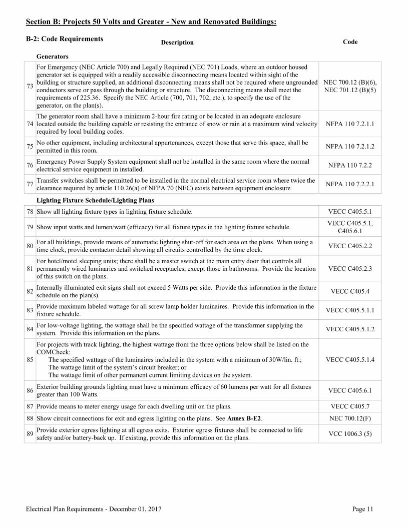
For Emergency (NEC Article 700) and Legally Required (NEC 701) Loads, where an outdoor housed generator set is equipped with a readily accessible disconnecting means located within sight of the building or structure supplied, an additional disconnecting means shall not be required where ungrounded conductors serve or pass through the building or structure. The disconnecting means shall meet the requirements of 225.36. Specify the NEC Article (700, 701, 702, etc.), to specify the use of the generator, on the plan(s). [NEC 700.12 (B)(6), NEC 701.12 (B)(5)]
Section B-2.74
Note
The generator room shall have a minimum 2-hour fire rating or be located in an adequate enclosure located outside the building capable or resisting the entrance of snow or rain at a maximum wind velocity required by local building codes. [NFPA 110 7.2.1.1]
Section B-2.75
Note
No other equipment, including architectural appurtenances, except those that serve this space, shall be permitted in this room. [NFPA 110 7.2.1.2]
Section B-2.76
Note
Emergency Power Supply System equipment shall not be installed in the same room where the normal electrical service equipment in installed. [NFPA 110 7.2.2]
Section B-2.77
Note
Transfer switches shall be permitted to be installed in the normal electrical service room where twice the clearance required by article 110.26(a) of NFPA 70 (NEC) exists between equipment enclosure. [NFPA 110 7.2.2.1]
Section B-2.78
Note
Show all lighting fixture types in lighting fixture schedule. [VECC C405.5.1]
Section B-2.79
Note
Show input watts and lumen/watt (efficacy) for all fixture types in the lighting fixture schedule. [VECC C405.5.1, C405.6.1]
Section B-2.80
Note
For all buildings, provide means of automatic lighting shut-off for each area on the plans. When using a time clock, provide contactor detail showing all circuits controlled by the time clock. [VECC C405.2.2]
Section B-2.81
Note
For hotel/motel sleeping units; there shall be a master switch at the main entry door that controls all permanently wired luminaries and switched receptacles, except those in bathrooms. Provide the location of this switch on the plans. [VECC C405.2.3]
Section B-2.82
Note
Internally illuminated exit signs shall not exceed 5 Watts per side. Provide this information in the fixture schedule on the plan(s). [VECC C405.4]
Section B-2.83
Note
Provide maximum labeled wattage for all screw lamp holder luminaires. Provide this information in the fixture schedule. [VECC C405.5.1.1]
Section B-2.84
Note
For low-voltage lighting, the wattage shall be the specified wattage of the transformer supplying the system. Provide this information on the plans. [VECC C405.5.1.2]
Section B-2.85
Note
For projects with track lighting, the highest wattage from the three options below shall be listed on the COMCheck: The specified wattage of the luminaires included in the system with a minimum of 30W/lin. ft.; The wattage limit of the system’s circuit breaker; or The wattage limit of other permanent current limiting devices on the system. [VECC C405.5.1.4]
Section B-2.86
Note
Exterior building grounds lighting must have a minimum efficacy of 60 lumens per watt for all fixtures greater than 100 Watts. Provide lumen/watt information for exterior lighting fixtures. [VECC C405.6.1]
Section B-2.87
Note
Provide means to meter energy usage for each unit on the plans. [VECC C405.7]
Section B-2.88
Note
Show circuit connections for exit and egress lighting. See Annex B-E2. [NEC 700.12(F)]
Section B-2.89
Note
Provide exterior egress lighting at all egress exits. Exterior egress fixtures shall be connected to life safety and/or battery-back up. If existing, provide this information on the plans. [VCC 1006.3 (5)]
Section B-2.90
Note
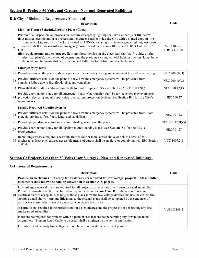
Prior to final inspection, all projects that require emergency lighting shall have either (i) or (ii) below: (i) A master electrician, or a professional engineer shall provide the City with a signed copy of the Emergency Lighting Test Checklist located in ANNEX E stating that all emergency lighting test meets or exceeds IBC for normal and emergency power based on Sections 1006.2 and 1006.3.1 of the IBC. OR (ii) provide normal and emergency lighting photometrics on the electrical plan(s). Provide, on the electrical plan(s), the method of determining the photometrics and all total light loss factors, lamp lumen depreciation, luminaire dirt depreciation, and ballast factor utilized in the calculations. [VCC 1006.2, 1006.3.1, 1021]
Section B-2.91
Note
Provide means on the plans to show separation of emergency wiring and equipment from all other wiring. [NEC 700.10(B)]
Section B-2.92
Note
Provide sufficient details on the plans to show how the emergency systems will be protected from complete failure due to fire, flood, icing, and vandalism. [NEC 700.10(C)]
Section B-2.93
Note
Plans shall show all specific requirements for unit equipment. See exception in Article 700.12(F). [NEC 700.12(F)]
Section B-2.94
Note
Provide coordination study for all emergency loads. Coordination shall be for the emergency overcurrent protection device(s) and all supply side overcurrent protection devices. See Section D-1 for the City’s requirements. [NEC 700.27]
Section B-2.95
Note
Provide sufficient details on the plans to show how the emergency systems will be protected from complete failure due to fire, flood, icing, and vandalism. [NEC 701.12]
Section B-2.96
Note
Provide proper disconnecting means for outside generator on the plans. [NEC 701.12(B)(5)]
Section B-2.97
Note
Provide coordination study for all legally required standby loads. See Section D-1 for the City’s requirements. [NEC 701.27]
Section B-2.98
Note
In buildings where a required accessible floor is four or more stories above or below a level of exit discharge, at least one required accessible means of egress shall be an elevator complying with Section 1007.4. [VCC 1007.2.1]
Section B-2.66
Note
For equipment located in either a damp or wet location, provide proper protection for that equipment based on the requirements in Chapter 4 of the National Electrical Code. [NEC Chapter 4]
Electrical Plan Requirements - December 01, 2016 Page 25
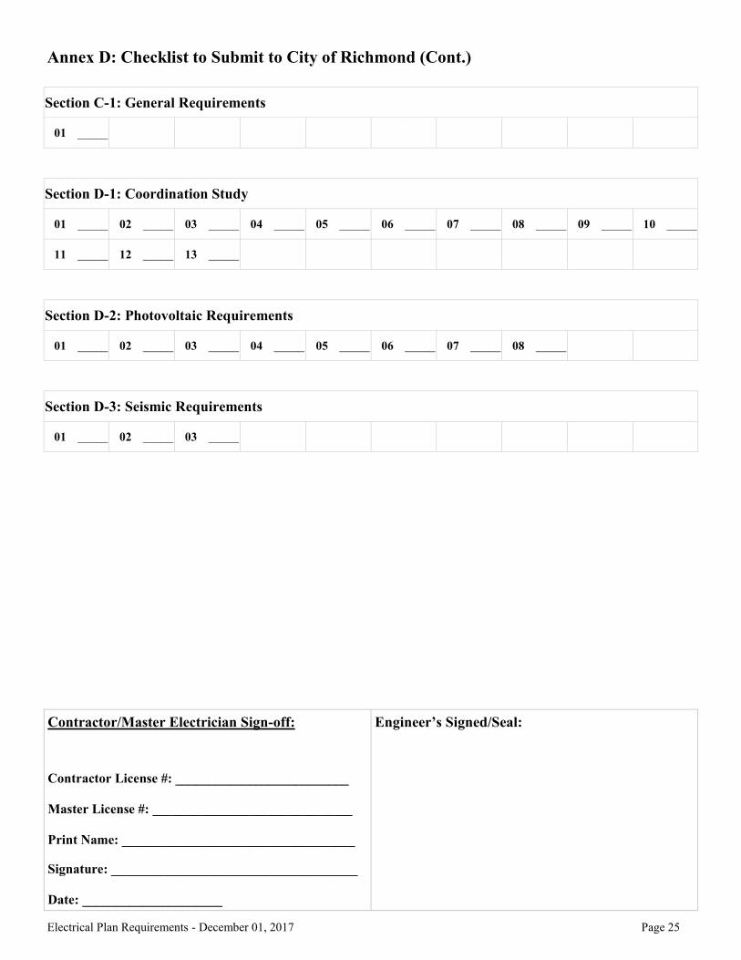
Annex D: Checklist to Submit to City of Richmond (Cont.)
Electrical Plan Requirements - June 01, 2017 Electrical Plan Requirements - December 01, 2017
Section C-1.01
Note
Low voltage electrical plans are required for all projects that penetrate any fire/smoke rated assemblies. Provide information on the plan based on requirements in Section A and B. Submission of original electrical plans is acceptable, as long as those plans show the low voltage devices and has the correct fire stopping detail shown. Any modifications to the original plans shall be completed by the engineer of records (or master electrician or contractor who signed the plans).
Section D-1.01
Note
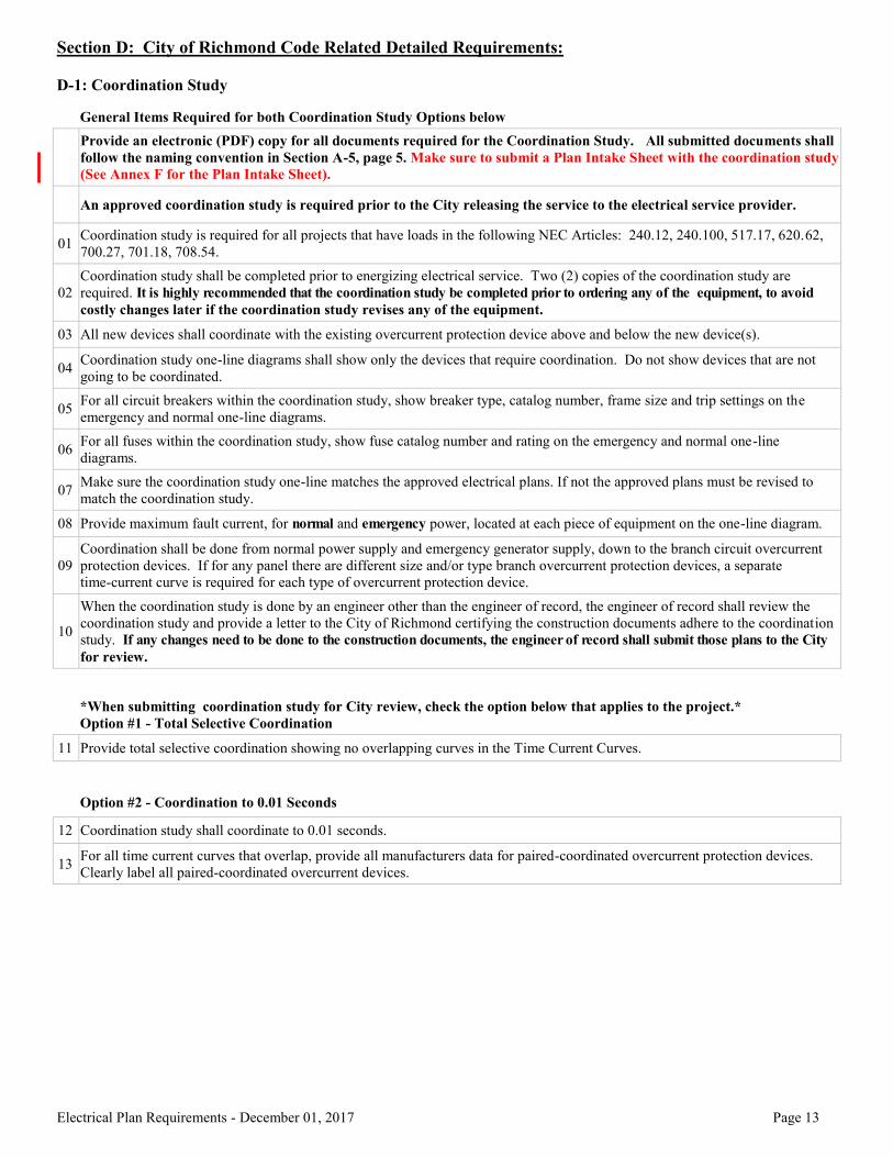
Coordination study is required for all projects that have loads in the following NEC Articles: 240.12, 240.100, 517.17, 620.62, 700.27, 701.18, 708.54.
Section D-1.02
Note
Coordination study shall be completed prior to energizing electrical service. Two (2) copies of the coordination study are required. It is highly recommended that the coordination study be completed prior to ordering any of the equipment, to avoid costly changes later if the coordination study revises any of the equipment.
Section D-1.03
Note
All new devices shall coordinate with the existing overcurrent protection device above and below the new device(s).
Section D-1.04
Note
Coordination study one-line diagrams shall show only the devices that require coordination. Do not show devices that are not going to be coordinated.
Section D-1.05
Note
For all circuit breakers within the coordination study, show breaker type, catalog number, frame size and trip settings on the emergency and normal one-line diagrams.
Section D-1.06
Note
For all fuses within the coordination study, show fuse catalog number and rating on the emergency and normal one-line diagrams.
Section D-1.07
Note
Make sure the coordination study one-line matches the approved electrical plans. If not the approved plans must be revised to match the coordination study.
Section D-1.08
Note
Provide maximum fault current, for normal and emergency power, located at each piece of equipment on the one-line diagram.
Section D-1.09
Note
Coordination shall be done from normal power supply and emergency generator supply, down to the branch circuit overcurrent protection devices. If for any panel there are different size and/or type branch overcurrent protection devices, a separate time-current curve is required for each type of overcurrent protection device.
Section D-1.10
Note
When the coordination study is done by an engineer other than the engineer of record, the engineer of record shall review the coordination study and provide a letter to the City of Richmond certifying the construction documents adhere to the coordination study. If any changes need to be done to the construction documents, the engineer of record shall submit those plans to the City for review.
Section D-1.11
Note
Provide total selective coordination showing no overlapping curves in the Time Current Curves.
Section D-1.12
Note
Coordination study shall coordinate to 0.01 seconds.
Section D-1.13
Note
For all time current curves that overlap, provide all manufacturers data for paired-coordinated overcurrent protection devices. Clearly label all paired-coordinated overcurrent devices.
Section D-2.01
Note
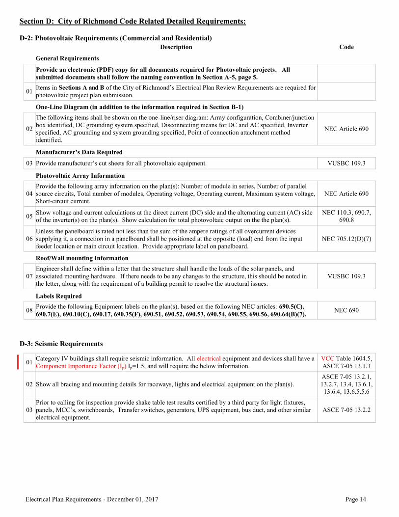
Items in Sections A and B of the City of Richmond’s Electrical Plan Review Requirements are required for photovoltaic projects.
Section D-2.02
Note
The following items shall be shown on the one-line/riser diagram: Array configuration, Combiner/junction box identified, DC grounding system specified, Disconnecting means for DC and AC specified, Inverter specified, AC grounding and system grounding specified, Point of connection attachment method identified. [NEC Article 690]
Section D-2.03
Note
Provide manufacturer’s cut sheets for all photovoltaic equipment. [VUSBC 109.3]
Section D-2.04
Note
Provide the following array information on the plans: Number of module in series, Number of parallel source circuits, Total number of modules, Operating voltage, Operating current, Maximum system voltage, Short-circuit current. [NEC Article 690]
Section D-2.05
Note
Show voltage and current calculations at the direct current (DC) side and the alternating current (AC) side of the inverter(s) on the plan(s). Show calculation for total photovoltaic output on the the plan(s). [NEC 110.3, 690.7, 690.8]
Section D-2.06
Note
Unless the panelboard is rated not less than the sum of the ampere ratings of all overcurrent devices supplying it, a connection in a panelboard shall be positioned at the opposite (load) end from the input feeder location or main circuit location. Provide appropriate label on panelboard. [NEC 705.12(D)(7)]
Section D-2.07
Note
Engineer shall define within a letter that the structure shall handle the loads of the solar panels, and associated mounting hardware. If there needs to be any changes to the structure, this should be noted in the letter, along with the requirement of a building permit to resolve the structural issues. [VUSBC 109.3]
Section D-2.08
Note
Provide the following Equipment labels on the plans, based on the following NEC articles: 690.5(C), 690.7(E), 690.10(C), 690.17, 690.35(F), 690.51, 690.52, 690.53, 690.54, 690.55, 690.56, 690.64(B)(7). [NEC 690]
Section D-3.01
Note
Category IV buildings shall require seismic information. All electrical equipment and devices shall have a Component Importance Factor (Ip) Ip=1.5, and will require the below information. [VCC Table 1604.5, ASCE 7-05 13.1.3]
Section D-3.02
Note
Show all bracing and mounting details for raceways, lights and electrical equipment. [ASCE 7-05 13.2.1, 13.2.7, 13.4, 13.6.1, 13.6.4, 13.6.5.5.6]
Section D-3.03
Note
Prior to calling for inspection provide shake table test results certified by a third party for light fixtures, panels, MCC’s, switchboards, Transfer switches, generators, UPS equipment, bus duct, and other similar electrical equipment. [ASCE 7-05 13.2.2]
Electrical Plan Requirements - December 01, 2016 Page 26
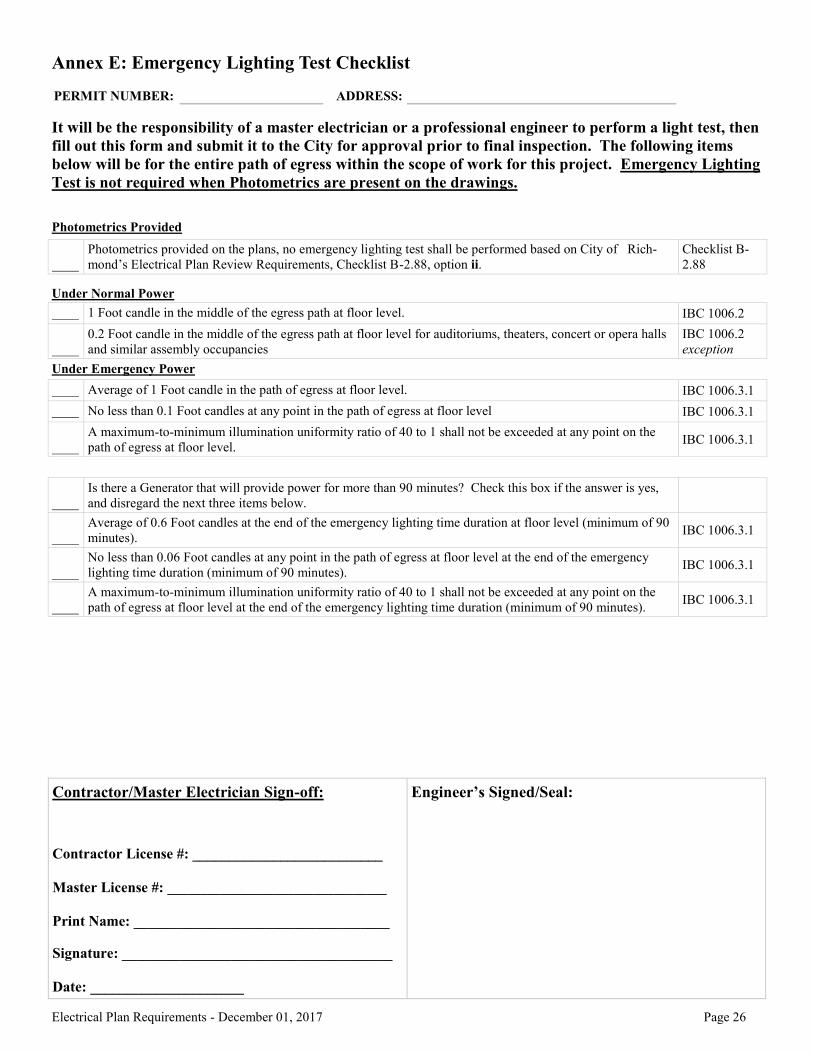
Annex E: Emergency Lighting Test Checklist
It will be the responsibility of a master electrician or a professional engineer to perform a light test, then
fill out this form and submit it to the City for approval prior to final inspection. The following items
below will be for the entire path of egress within the scope of work for this project. Emergency Lighting
Test is not required when Photometrics are present on the drawings.
Photometrics Provided
____
Photometrics provided on the plans, no emergency lighting test shall be performed based on City of Rich-
mond’s Electrical Plan Review Requirements, Checklist B-2.88, option ii.
Checklist B-
2.88
Under Normal Power
____ 1 Foot candle in the middle of the egress path at floor level. IBC 1006.2
____
0.2 Foot candle in the middle of the egress path at floor level for auditoriums, theaters, concert or opera halls
and similar assembly occupancies
IBC 1006.2
exception
Under Emergency Power
____ Average of 1 Foot candle in the path of egress at floor level. IBC 1006.3.1
____ No less than 0.1 Foot candles at any point in the path of egress at floor level IBC 1006.3.1
____
A maximum-to-minimum illumination uniformity ratio of 40 to 1 shall not be exceeded at any point on the
path of egress at floor level. IBC 1006.3.1
____
Is there a Generator that will provide power for more than 90 minutes? Check this box if the answer is yes,
and disregard the next three items below.
____
Average of 0.6 Foot candles at the end of the emergency lighting time duration at floor level (minimum of 90
minutes). IBC 1006.3.1
____
No less than 0.06 Foot candles at any point in the path of egress at floor level at the end of the emergency
lighting time duration (minimum of 90 minutes). IBC 1006.3.1
____
A maximum-to-minimum illumination uniformity ratio of 40 to 1 shall not be exceeded at any point on the
path of egress at floor level at the end of the emergency lighting time duration (minimum of 90 minutes). IBC 1006.3.1