A simplified nonlinear controller for transient stability enhancement of multimachine power systems using SSSC device Jean de Dieu Nguimfack-Ndongmo a , Godpromesse Kenné a,⇑ , René Kuate-Fochie a , André Cheukem a , Hilaire Bertrand Fotsin b , Françoise Lamnabhi-Lagarrigue c a Laboratoire d’Automatique et d’Informatique Appliquée (LAIA), Département de Génie Électrique, IUT FOTSO Victor Bandjoun, Université de Dschang, B.P. 134 Bandjoun, Cameroon b Laboratoire d’Electronique, d’Electrotechnique et d’Automatique (LEEA), Département de Physique, Faculté des Sciences, Université de Dschang, Cameroon c Laboratoire des Signaux et Systèmes (LSS), CNRS, Université de Paris XI, 91192 Gif-Sur-Yvette, France article info Article history: Received 22 August 2012 Received in revised form 26 July 2013 Accepted 22 August 2013 Keywords: Power system Transient stability FACTS SSSC DFIG Lyapunov theory abstract In this paper, a simplified nonlinear method is proposed to enhance the transient stability of multima- chine power system by using a Static Synchronous Series Compensator (SSSC). The rate of dissipation of transient energy is used to determine the additional damping provided by a SSSC. The proposed algo- rithm is based on the direct Lyapunov method. The simplicity of the proposed scheme and its robustness with respect to large disturbances constitute the main positive features. Simulation results in the case of 3-machines power system show the effectiveness of the proposed method under large disturbances (3-phase and single phase short-circuits). Ó 2013 Elsevier Ltd. All rights reserved. 1. Introduction 1.1. Antecedents and motivations The fast development of the power electronics industry has per- mitted the use of Flexible AC Transmission Systems (FACTS) con- trollers in power systems. The potential benefits with the utilization of FACTS devices include reduction of operation and transmission investment costs, increasing system security and reli- ability, and increasing transfer capabilities in a deregulated envi- ronment [1]. The detailed explanations about the FACTS controllers are well documented in the literature and can be found in [2–4]. Static synchronous series compensator (SSSC) is one of the important type of FACTS family which can be installed in series in the transmission lines. SSSC is very effective in controlling power flow in a transmission line with the capability to change its reac- tance characteristic from capacitive to inductive [4–6]. An auxiliary stabilizing signal can also be superimposed on the power flow control function of the SSSC to improve power system stability [7]. In [7], the author proposed a SSSC damping controller based on phase compensation for single-machine infinite-bus and an objective function based searching algorithm is suggested for mul- timachine power system. Menniti et al. [8] proposed the use of SSSC to damp the transient frequency deviation in a deregulated electric power system. This method is based on the application of the overlapping decomposition technique to design a decentralized control law of a SSSC device where a multi-area power system is decomposed into two decoupled subsystems. Ngamroo and Tippa- yachai [9] developed a robust decentralized frequency stabilizers design of SSSC by taking system uncertainties into consideration and proposed to use a SSSC in an interconnected power system which was subjected to load disturbances with frequency variation in the vicinity of the inter-area oscillation mode. In [10], stability analysis and design of the SSSC controller based on modal analysis, nonlinear simulations, pole placement techniques and time and frequency response techniques are investigated. In [11], PID struc- tures are proposed to modulate the injected voltage through differ- ential evolution algorithm. In [6], the authors propose a 12-pulse based SSSC with and without superconducting magnetic energy storage for enhancing the voltage stability and power oscillation damping in multi area system. These proposals are based on small disturbance analysis that requires linearization of the system involved. However, linear methods cannot properly capture complex dynamics of the system, 0142-0615/$ - see front matter Ó 2013 Elsevier Ltd. All rights reserved. http://dx.doi.org/10.1016/j.ijepes.2013.08.019 ⇑ Corresponding author. Tel.: +237 77 59 52 19. E-mail addresses: [email protected](J.d.D. Nguimfack-Ndongmo), [email protected](G. Kenné), [email protected](R. Kuate-Fochie), acheuk_ [email protected](A. Cheukem), [email protected](H.B. Fotsin), [email protected](F. Lamnabhi-Lagarrigue). Electrical Power and Energy Systems 54 (2014) 650–657 Contents lists available at ScienceDirect Electrical Power and Energy Systems journal homepage: www.elsevier.com/locate/ijepes
Transcript
Electrical Power and Energy Systems 54 (2014) 650–657
Contents lists available at ScienceDirect
Electrical Power and Energy Systems
journal homepage: www.elsevier .com/locate / i jepes
A simplified nonlinear controller for transient stability enhancementof multimachine power systems using SSSC device
0142-0615/$ - see front matter � 2013 Elsevier Ltd. All rights reserved.http://dx.doi.org/10.1016/j.ijepes.2013.08.019
Jean de Dieu Nguimfack-Ndongmo a, Godpromesse Kenné a,⇑, René Kuate-Fochie a, André Cheukem a,Hilaire Bertrand Fotsin b, Françoise Lamnabhi-Lagarrigue c
a Laboratoire d’Automatique et d’Informatique Appliquée (LAIA), Département de Génie Électrique, IUT FOTSO Victor Bandjoun, Université de Dschang, B.P. 134 Bandjoun, Cameroonb Laboratoire d’Electronique, d’Electrotechnique et d’Automatique (LEEA), Département de Physique, Faculté des Sciences, Université de Dschang, Cameroonc Laboratoire des Signaux et Systèmes (LSS), CNRS, Université de Paris XI, 91192 Gif-Sur-Yvette, France
a r t i c l e i n f o
Article history:Received 22 August 2012Received in revised form 26 July 2013Accepted 22 August 2013
Keywords:Power systemTransient stabilityFACTSSSSCDFIGLyapunov theory
a b s t r a c t
In this paper, a simplified nonlinear method is proposed to enhance the transient stability of multima-chine power system by using a Static Synchronous Series Compensator (SSSC). The rate of dissipationof transient energy is used to determine the additional damping provided by a SSSC. The proposed algo-rithm is based on the direct Lyapunov method. The simplicity of the proposed scheme and its robustnesswith respect to large disturbances constitute the main positive features. Simulation results in the caseof 3-machines power system show the effectiveness of the proposed method under large disturbances(3-phase and single phase short-circuits).
� 2013 Elsevier Ltd. All rights reserved.
1. Introduction
1.1. Antecedents and motivations
The fast development of the power electronics industry has per-mitted the use of Flexible AC Transmission Systems (FACTS) con-trollers in power systems. The potential benefits with theutilization of FACTS devices include reduction of operation andtransmission investment costs, increasing system security and reli-ability, and increasing transfer capabilities in a deregulated envi-ronment [1]. The detailed explanations about the FACTScontrollers are well documented in the literature and can be foundin [2–4]. Static synchronous series compensator (SSSC) is one of theimportant type of FACTS family which can be installed in series inthe transmission lines. SSSC is very effective in controlling powerflow in a transmission line with the capability to change its reac-tance characteristic from capacitive to inductive [4–6]. An auxiliarystabilizing signal can also be superimposed on the power flowcontrol function of the SSSC to improve power system stability
[7]. In [7], the author proposed a SSSC damping controller basedon phase compensation for single-machine infinite-bus and anobjective function based searching algorithm is suggested for mul-timachine power system. Menniti et al. [8] proposed the use ofSSSC to damp the transient frequency deviation in a deregulatedelectric power system. This method is based on the application ofthe overlapping decomposition technique to design a decentralizedcontrol law of a SSSC device where a multi-area power system isdecomposed into two decoupled subsystems. Ngamroo and Tippa-yachai [9] developed a robust decentralized frequency stabilizersdesign of SSSC by taking system uncertainties into considerationand proposed to use a SSSC in an interconnected power systemwhich was subjected to load disturbances with frequency variationin the vicinity of the inter-area oscillation mode. In [10], stabilityanalysis and design of the SSSC controller based on modal analysis,nonlinear simulations, pole placement techniques and time andfrequency response techniques are investigated. In [11], PID struc-tures are proposed to modulate the injected voltage through differ-ential evolution algorithm. In [6], the authors propose a 12-pulsebased SSSC with and without superconducting magnetic energystorage for enhancing the voltage stability and power oscillationdamping in multi area system.
These proposals are based on small disturbance analysis thatrequires linearization of the system involved. However, linearmethods cannot properly capture complex dynamics of the system,
J.d.D. Nguimfack-Ndongmo et al. / Electrical Power and Energy Systems 54 (2014) 650–657 651
especially during major disturbances. In [12,13], the authors pro-posed nonlinear control law based on Lyapunov stability conceptto determine the additional damping provided by Controllable Ser-ies Capacitor (CSC). However, the time-derivative of the signalsused in the control law are obtained by using band-pass filtersand the problem of noise is not completely solve. The Lyapunov’sstability theory have also been used to design a control law forSSSC in [14,15]. But in these contributions the formulation of theproposed control in the case of multimachine configuration hasnot been investigated.
Given that wind power is becoming increasingly significantsource of energy, many power systems contain nowadays bothsynchronous generators (SGs) and doubly fed induction generators(DFIGs). It is known that a DFIG can contribute to stabilize a powersystem when it is subjected to small perturbations [16]. To the bestof our knowledge, the impact of DFIG after large disturbances hasnot been investigated in multimachine power systems with thepresence of FACTS device.
1.2. Main contribution
A simplified nonlinear method is proposed to enhance the tran-sient stability of multimachine power system using SSSC device byexploiting the concepts developed in [12,13]. A new nonlinear con-trol scheme has been derived and the time-derivative signals usedin the proposed control scheme has been estimated in finite timeby using second order sliding mode observers. The impact of DFIGsafter large disturbances with the presence of FACTS device in mul-timachine power system has been investigated.
1.3. Structure of the paper
The paper is organized as follows. In Section 2, the injectionmodel of the SSSC is described. The design procedure of the formu-lation of the proposed control algorithm is presented in Section 3.Simulation results are presented in Section 4 to demonstrate theperformance of the proposed controller. Finally, in Section 5, someconcluding remarks end the paper.
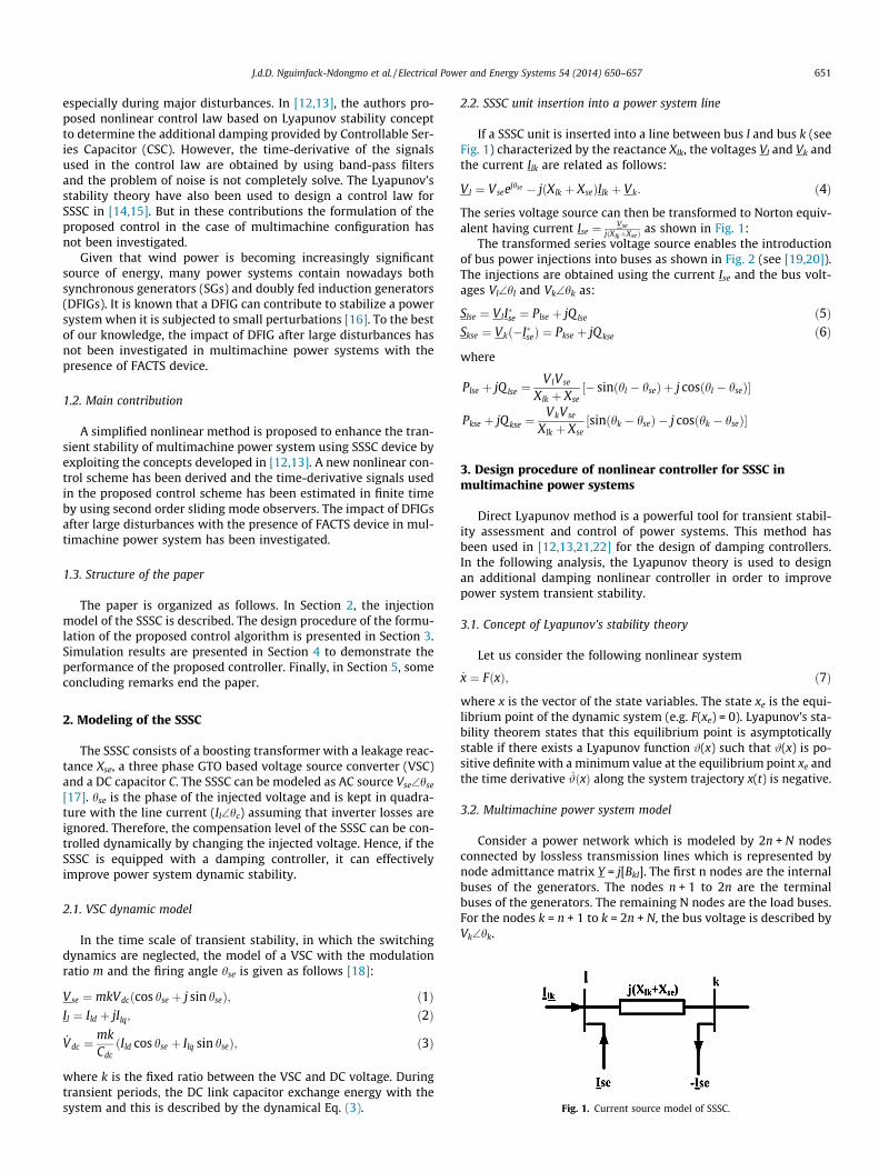
Fig. 1. Current source model of SSSC.
2. Modeling of the SSSC
The SSSC consists of a boosting transformer with a leakage reac-tance Xse, a three phase GTO based voltage source converter (VSC)and a DC capacitor C. The SSSC can be modeled as AC source Vse\hse
[17]. hse is the phase of the injected voltage and is kept in quadra-ture with the line current (Il\hc) assuming that inverter losses areignored. Therefore, the compensation level of the SSSC can be con-trolled dynamically by changing the injected voltage. Hence, if theSSSC is equipped with a damping controller, it can effectivelyimprove power system dynamic stability.
2.1. VSC dynamic model
In the time scale of transient stability, in which the switchingdynamics are neglected, the model of a VSC with the modulationratio m and the firing angle hse is given as follows [18]:
Vse ¼ mkVdcðcos hse þ j sin hseÞ; ð1ÞIl ¼ Ild þ jIlq; ð2Þ
_Vdc ¼mkCdcðIld cos hse þ Ilq sin hseÞ; ð3Þ
where k is the fixed ratio between the VSC and DC voltage. Duringtransient periods, the DC link capacitor exchange energy with thesystem and this is described by the dynamical Eq. (3).
2.2. SSSC unit insertion into a power system line
If a SSSC unit is inserted into a line between bus l and bus k (seeFig. 1) characterized by the reactance Xlk, the voltages Vl and Vk andthe current Ilk are related as follows:
Vl ¼ Vseejhse � jðXlk þ XseÞIlk þ Vk: ð4Þ
The series voltage source can then be transformed to Norton equiv-alent having current Ise ¼ Vse
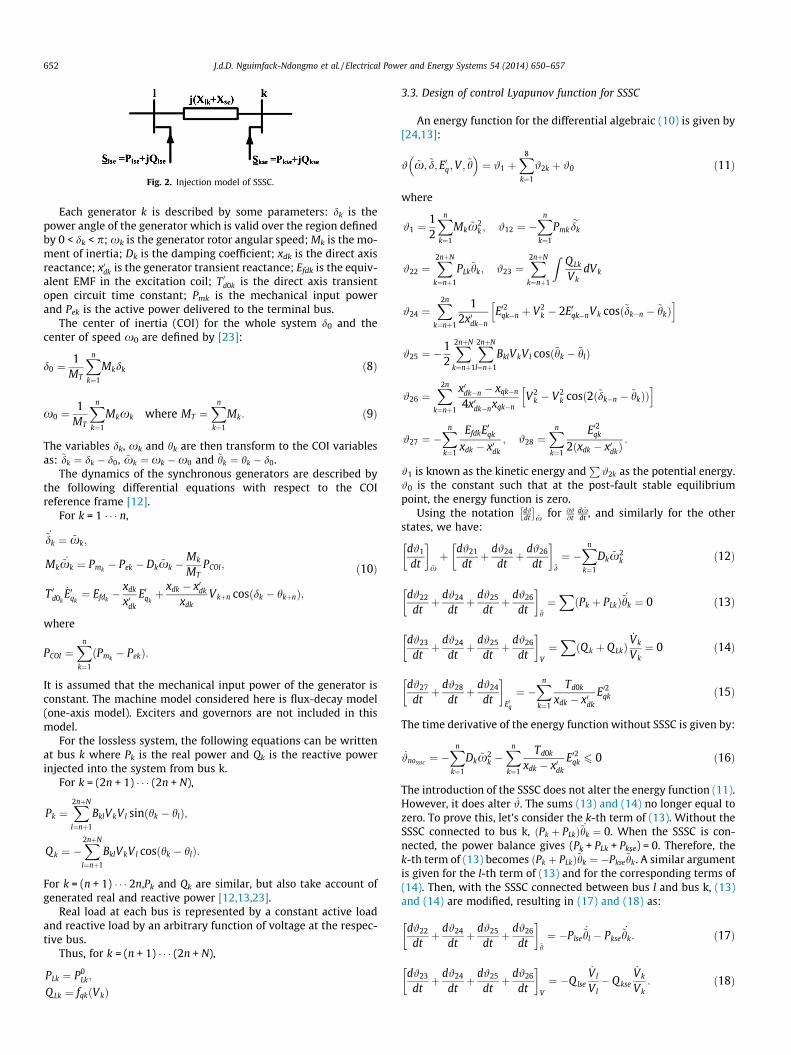
jðXlkþXseÞ as shown in Fig. 1:The transformed series voltage source enables the introduction
of bus power injections into buses as shown in Fig. 2 (see [19,20]).The injections are obtained using the current Ise and the bus volt-ages Vl\hl and Vk\hk as:
3. Design procedure of nonlinear controller for SSSC inmultimachine power systems
Direct Lyapunov method is a powerful tool for transient stabil-ity assessment and control of power systems. This method hasbeen used in [12,13,21,22] for the design of damping controllers.In the following analysis, the Lyapunov theory is used to designan additional damping nonlinear controller in order to improvepower system transient stability.
3.1. Concept of Lyapunov’s stability theory
Let us consider the following nonlinear system
_x ¼ FðxÞ; ð7Þ
where x is the vector of the state variables. The state xe is the equi-librium point of the dynamic system (e.g. F(xe) = 0). Lyapunov’s sta-bility theorem states that this equilibrium point is asymptoticallystable if there exists a Lyapunov function #(x) such that #(x) is po-sitive definite with a minimum value at the equilibrium point xe andthe time derivative _#ðxÞ along the system trajectory x(t) is negative.
3.2. Multimachine power system model
Consider a power network which is modeled by 2n + N nodesconnected by lossless transmission lines which is represented bynode admittance matrix Y = j[Bkl]. The first n nodes are the internalbuses of the generators. The nodes n + 1 to 2n are the terminalbuses of the generators. The remaining N nodes are the load buses.For the nodes k = n + 1 to k = 2n + N, the bus voltage is described byVk\hk.
Fig. 2. Injection model of SSSC.
652 J.d.D. Nguimfack-Ndongmo et al. / Electrical Power and Energy Systems 54 (2014) 650–657
Each generator k is described by some parameters: dk is thepower angle of the generator which is valid over the region definedby 0 < dk < p; xk is the generator rotor angular speed; Mk is the mo-ment of inertia; Dk is the damping coefficient; xdk is the direct axisreactance; x0dk is the generator transient reactance; Efdk is the equiv-alent EMF in the excitation coil; T 0d0k is the direct axis transientopen circuit time constant; Pmk is the mechanical input powerand Pek is the active power delivered to the terminal bus.
The center of inertia (COI) for the whole system d0 and thecenter of speed x0 are defined by [23]:
d0 ¼1
MT
Xn
k¼1
Mkdk ð8Þ
x0 ¼1
MT
Xn
k¼1
Mkxk where MT ¼Xn
k¼1
Mk: ð9Þ
The variables dk, xk and hk are then transform to the COI variablesas: ~dk ¼ dk � d0, ~xk ¼ xk �x0 and ~hk ¼ hk � d0.
The dynamics of the synchronous generators are described bythe following differential equations with respect to the COIreference frame [12].
For k = 1 � � � n,
_~dk ¼ ~xk;
Mk_~xk ¼ Pmk
� Pek � Dk ~xk �Mk
MTPCOI;
T 0d0k_E0qk¼ Efdk
� xdk
x0dk
E0qkþ xdk � x0dk
xdkVkþn cosðdk � hkþnÞ;
ð10Þ
where
PCOI ¼Xn
k¼1
ðPmk� PekÞ:
It is assumed that the mechanical input power of the generator isconstant. The machine model considered here is flux-decay model(one-axis model). Exciters and governors are not included in thismodel.
For the lossless system, the following equations can be writtenat bus k where Pk is the real power and Qk is the reactive powerinjected into the system from bus k.
For k = (2n + 1) � � � (2n + N),
Pk ¼X2nþN
l¼nþ1
BklVkVl sinðhk � hlÞ;
Q k ¼ �X2nþN
l¼nþ1
BklVkVl cosðhk � hlÞ:
For k = (n + 1) � � � 2n,Pk and Qk are similar, but also take account ofgenerated real and reactive power [12,13,23].
Real load at each bus is represented by a constant active loadand reactive load by an arbitrary function of voltage at the respec-tive bus.
Thus, for k = (n + 1) � � � (2n + N),
PLk ¼ P0Lk;
Q Lk ¼ fqkðVkÞ
3.3. Design of control Lyapunov function for SSSC
An energy function for the differential algebraic (10) is given by[24,13]:
# ~x; ~d; E0q;V ; ~h� �
¼ #1 þX8
k¼1
#2k þ #0 ð11Þ
where
#1 ¼12
Xn
k¼1
Mk ~x2k ; #12 ¼ �
Xn
k¼1
Pmkedk
#22 ¼X2nþN
k¼nþ1
PLk~hk; #23 ¼
X2nþN
k¼nþ1
ZQLk
VkdVk
#24 ¼X2n
k¼nþ1
12x0dk�n
E02qk�n þ V2k � 2E0qk�nVk cosð~dk�n � ~hkÞ
h i
#25 ¼ �12
X2nþN
k¼nþ1
X2nþN
l¼nþ1
BklVkVl cosð~hk � ~hlÞ
#26 ¼X2n
k¼nþ1
x0dk�n � xqk�n
4x0dk�nxqk�nV2
k � V2k cosð2ð~dk�n � ~hkÞÞ
h i
#27 ¼ �Xn
k¼1
EfdkE0qk
xdk � x0dk
; #28 ¼Xn
k¼1
E02qk
2ðxdk � x0dkÞ:
#1 is known as the kinetic energy andP#2k as the potential energy.
#0 is the constant such that at the post-fault stable equilibriumpoint, the energy function is zero.
Using the notation d#dt
� �~x for @#
@td ~xdt , and similarly for the other
states, we have:
d#1
dt
� �~xþ d#21
dtþ d#24
dtþ d#26
dt
� �~d
¼ �Xn
k¼1
Dk ~x2k ð12Þ
d#22
dtþ d#24
dtþ d#25
dtþ d#26
dt
� �~h
¼XðPk þ PLkÞ _~hk ¼ 0 ð13Þ
d#23
dtþ d#24
dtþ d#25
dtþ d#26
dt
� �V
¼XðQ k þ Q LkÞ
_Vk
Vk¼ 0 ð14Þ
d#27
dtþ d#28
dtþ d#24
dt
� �E0q
¼ �Xn
k¼1
Td0k
xdk � x0dk
E02qk ð15Þ
The time derivative of the energy function without SSSC is given by:
_#nosssc ¼ �Xn
k¼1
Dk ~x2k �
Xn
k¼1
Td0k
xdk � x0dk
E02qk 6 0 ð16Þ
The introduction of the SSSC does not alter the energy function (11).However, it does alter _#. The sums (13) and (14) no longer equal tozero. To prove this, let’s consider the k-th term of (13). Without theSSSC connected to bus k, ðPk þ PLkÞ _~hk ¼ 0. When the SSSC is con-nected, the power balance gives (Pk + PLk + Pkse) = 0. Therefore, thek-th term of (13) becomes ðPk þ PLkÞ _~hk ¼ �Pkse
_~hk. A similar argumentis given for the l-th term of (13) and for the corresponding terms of(14). Then, with the SSSC connected between bus l and bus k, (13)and (14) are modified, resulting in (17) and (18) as:
d#22
dtþ d#24
dtþ d#25
dtþ d#26
dt
� �~h
¼ �Plse_~hl � Pkse
_~hk: ð17Þ
d#23
dtþ d#24
dtþ d#25
dtþ d#26
dt
� �V¼ �Q lse
_Vl
Vl� Q kse
_Vk
Vk: ð18Þ
J.d.D. Nguimfack-Ndongmo et al. / Electrical Power and Energy Systems 54 (2014) 650–657 653
where
Plse ¼ �VlVse
Xlk þ Xsesinðhl � hseÞ;
Qlse ¼VlVse
Xlk þ Xsecosðhl � hseÞ;
Pkse ¼VkVse
Xlk þ Xsesinðhk � hseÞ;
Qkse ¼ �VkVse
Xlk þ Xsecosðhk � hseÞ:
Since Plse = �Pkse for the SSSC and all control series devices, the timederivative of the energy function becomes:
_# ¼ �Xn
k¼1
Dk ~x2k �
Xn
k¼1
Td0k
xdk � x0dk
E02qk
� Plseð _~hl � _~hkÞ � Q lse
_Vl
Vl� Qkse
_Vk
Vkð19Þ
¼ _#nosssc þ _#sssc: ð20Þ
with
_#sssc ¼ � Plseð _~hl � _~hkÞ þ Qlse
_Vl
Vlþ Qkse
_Vk
Vk
" #ð21Þ
¼ VseVl
Xlk þ Xse
_~hlk sinðhl � hseÞ �_Vl
Vlcosðhl � hseÞ þ
_Vk
Vlcosðhk � hseÞ
" #; ð22Þ
where hlk ¼ hl � hk;_~hlk ¼ _~hl � _~hk.
Since the angle of the injected voltage hse is kept in quadraturewith the current (Ilk) through the SSSC,
let hse = hc + c with c ¼ � p2 and hc the angle of this current. Then
(22) becomes:
_#sssc ¼ �VseVl sin cXlk þ Xse
xlk cos hlc þ_Vl
Vlsin hlc �
_Vk
Vlsin hkc
" #: ð23Þ
where
hlc ¼ hl � hc;
hkc ¼ hk � hc;
xlk ¼ _~hlk ¼ _hlk:
The SSSC device contributes to the system damping if _#sssc isnegative. In order to achieve this objective, let (K > 0 is a designparameter and its value depend on the rating of the SSSC):
Vse ¼ Kx2lkV l; 0 6 Vse 6 Vmax
se ; ð24Þ
sin c ¼ sign xlk cos hlc þ_Vl
Vlsin hlc �
_Vk
Vlsin hkc
" #: ð25Þ
By choosing Vse and sinc as given by (24) and (25), (20) becomes:
_# ¼ �Xn
k¼1
Dk ~x2k �
Xn
k¼1
Td0k
xdk � x0dk
E02qk
� Kx2lkV2
l
Xlk þ Xsexlk cos hlc;þ
_Vl
Vlsin hlc �
_Vk
Vlsin hkc
����������
) _# 6 0: ð26Þ
This means that the introduction of the SSSC controlled by (24) and(25) provides additional damping of the power system.
Remarks:
(i) The above control law relies only on locally measurableinformation and is independent of system topology andmodeling of power system components.
The proposed control scheme is implementable in real-timesince it needs only measurable signals (Vi i = l, k; hlk) whichcan be obtained using phasor measurements [12].
(ii) The control law is in the form of pure derivatives. The time-derivatives of Vl, Vk and hlk cannot be obtained directly usingnumerical differentiation due to the presence of noise. In[13] band-pass filters tuned at the frequency range of inter-est have been used to avoid adverse action of the controllerof a CSC. However, the problem of noise is not completelysolve in this method. To overcome this problem, secondorder sliding mode observers must be used to estimate theabove unavailable states in finite time in Section 3.4.
3.4. State observers design
To estimate the unavailable time-derivative signals required forthe implementation of the above controller, let us introduce thefollowing variables:
xi1 ¼ Vi;
_xi1 ¼ xi2 ¼ _Vi; i ¼ l; k; ð27Þulk1 ¼ hlk;
_ulk1 ¼ ulk2 ¼ _hlk: ð28Þ
The following assumption will be considered until further notice:(i) The signals (Vi, i = l, k; hlk) are assumed to be continuous and
bounded.Let us consider now the following second-order sliding mode
observers [25,26]:
_xi1 ¼ xi2 þ z1xi; i ¼ l; k; ð29Þ
_xi2 ¼ z2xi:
_ulk1 ¼ ulk2 þ z1ulk
; ð30Þ_ulk2 ¼ z2
ulk:
where the variables z1xi; z2
xi, z1
ulkand z2
ulkare given by the following
expressions:
z1xi¼ �bxi
jxi1 � xi1j1=2signðxi1 � xi1Þ; ð31Þz2
xi¼ �axi
signðxi1 � xi1Þ;
z1ulk¼ �bulk
julk1 � ulk1j1=2signðulk1 � ulk1Þ; ð32Þz2
ulk¼ �aulk
signðulk1 � ulk1Þ:
and axi;bxi
;aulk, bulk
are positive tuning parameters. The solutions ofthe above observers are understood in the Filippov sense [25]. Tak-ing exi1
¼ xi1 � xi1, exi2¼ xi2 � xi2, eulk1
¼ ulk1 � xlk1, eulk2¼ ulk2 � ulk2,
the following dynamics errors equations are obtained:
_exi1¼ exi1
� bx1jexi1j1=2signðexi1
Þ; ð33Þ_exi2¼ �xi2 � axi1
signðexi1Þ;
_eulk1¼ eulk1
� bulk1jeulk1j1=2signðeulk1
Þ; ð34Þ_exlk2¼ �ulk2 � aulk1
signðeulk1Þ: ð35Þ
Assuming that the states of the system is bounded as reported inassumption (i) then there exists positive constants lxi2
and lulk2
such that the inequalities
jxi2j < lxi2ð36Þ
julk2j < lulk2ð37Þ
hold "t, xi1, xi2, ulk1 and ulk2. Then the variables of the observers con-verge to the states of the nonlinear reference model.
The proof of the finite time convergence of the estimated statesto the real states can be found in [25].
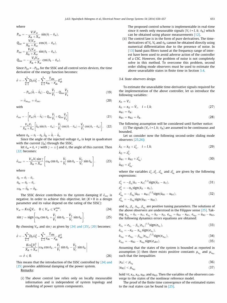
Fig. 3. WSCC system with SSSC.
0 1 2 3 4 5−0.1
00.10.2
e xl1(p
u)
0 1 2 3 4 5−0.2
0
0.2
e xk1(p
u)
0 1 2 3 4 5−0.2−0.1
00.1
u kl1(rd
)
Time (s)
VI observer error
VK observer error
θ KI observer error
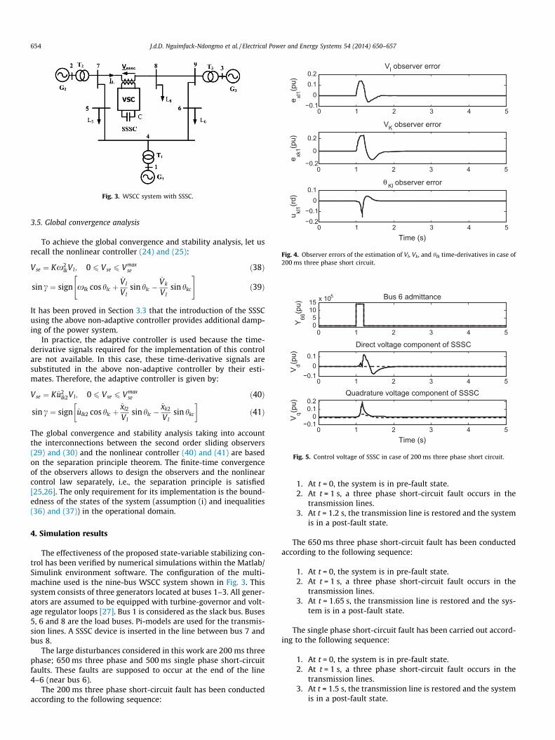
Fig. 4. Observer errors of the estimation of Vl, Vk, and hlk time-derivatives in case of200 ms three phase short circuit.
0 1 2 3 4 505
1015 x 105
Y 66(p
u)Bus 6 admittance
0 1 2 3 4 5−0.1
00.1
V d(pu)
Direct voltage component of SSSC
0 1 2 3 4 5−0.1
00.10.2
V q(pu)
Quadrature voltage component of SSSC
Time (s)
Fig. 5. Control voltage of SSSC in case of 200 ms three phase short circuit.
654 J.d.D. Nguimfack-Ndongmo et al. / Electrical Power and Energy Systems 54 (2014) 650–657
3.5. Global convergence analysis
To achieve the global convergence and stability analysis, let usrecall the nonlinear controller (24) and (25):
Vse ¼ Kx2lkVl; 0 6 Vse 6 Vmax
se ð38Þ
sin c ¼ sign xlk cos hlc þ_Vl
Vlsin hlc �
_Vk
Vlsin hkc
" #ð39Þ
It has been proved in Section 3.3 that the introduction of the SSSCusing the above non-adaptive controller provides additional damp-ing of the power system.
In practice, the adaptive controller is used because the time-derivative signals required for the implementation of this controlare not available. In this case, these time-derivative signals aresubstituted in the above non-adaptive controller by their esti-mates. Therefore, the adaptive controller is given by:
Vse ¼ Ku2lk2Vl; 0 6 Vse 6 Vmax
se ð40Þ
sin c ¼ sign ulk2 cos hlc þxl2
Vlsin hlc �
xk2
Vlsin hkc
� �ð41Þ
The global convergence and stability analysis taking into accountthe interconnections between the second order sliding observers(29) and (30) and the nonlinear controller (40) and (41) are basedon the separation principle theorem. The finite-time convergenceof the observers allows to design the observers and the nonlinearcontrol law separately, i.e., the separation principle is satisfied[25,26]. The only requirement for its implementation is the bound-edness of the states of the system (assumption (i) and inequalities(36) and (37)) in the operational domain.
4. Simulation results
The effectiveness of the proposed state-variable stabilizing con-trol has been verified by numerical simulations within the Matlab/Simulink environment software. The configuration of the multi-machine used is the nine-bus WSCC system shown in Fig. 3. Thissystem consists of three generators located at buses 1–3. All gener-ators are assumed to be equipped with turbine-governor and volt-age regulator loops [27]. Bus 1 is considered as the slack bus. Buses5, 6 and 8 are the load buses. Pi-models are used for the transmis-sion lines. A SSSC device is inserted in the line between bus 7 andbus 8.
The large disturbances considered in this work are 200 ms threephase; 650 ms three phase and 500 ms single phase short-circuitfaults. These faults are supposed to occur at the end of the line4–6 (near bus 6).
The 200 ms three phase short-circuit fault has been conductedaccording to the following sequence:
1. At t = 0, the system is in pre-fault state.2. At t = 1 s, a three phase short-circuit fault occurs in the
transmission lines.3. At t = 1.2 s, the transmission line is restored and the system
is in a post-fault state.
The 650 ms three phase short-circuit fault has been conductedaccording to the following sequence:
1. At t = 0, the system is in pre-fault state.2. At t = 1 s, a three phase short-circuit fault occurs in the
transmission lines.3. At t = 1.65 s, the transmission line is restored and the sys-
tem is in a post-fault state.
The single phase short-circuit fault has been carried out accord-ing to the following sequence:
1. At t = 0, the system is in pre-fault state.2. At t = 1 s, a three phase short-circuit fault occurs in the
transmission lines.3. At t = 1.5 s, the transmission line is restored and the system
is in a post-fault state.
0 1 2 3 4 5−0.2
00.2
ω1(ra
d/s)
0 1 2 3 4 5−1
−0.50
0.5
ω2(ra
d/s)
0 1 2 3 4 5−0.4−0.2
00.2
ω3(ra
d/s)
Time (s)
PI ControllerProposed Controller
(a)
0 1 2 3 4 5−8−6−4
δ 1(deg
.)
0 1 2 3 4 5152025
δ 2(deg
.)
0 1 2 3 4 50
5
10
δ 3(deg
.)
Time (s)
PI ControllerProposed Controller
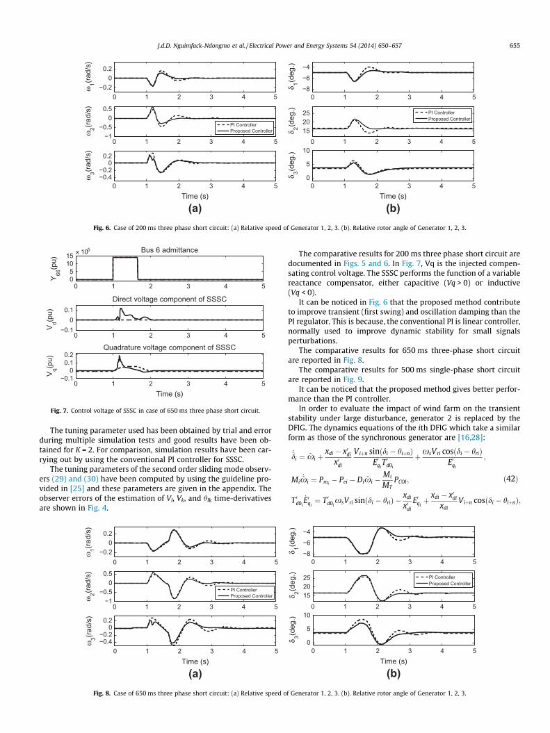
(b)Fig. 6. Case of 200 ms three phase short circuit: (a) Relative speed of Generator 1, 2, 3. (b). Relative rotor angle of Generator 1, 2, 3.
0 1 2 3 4 505
1015 x 105
Y 66(p
u)
Bus 6 admittance
0 1 2 3 4 5−0.1
00.1
V d(pu)
Direct voltage component of SSSC
0 1 2 3 4 5−0.1
00.10.2
V q(pu)
Quadrature voltage component of SSSC
Time (s)
Fig. 7. Control voltage of SSSC in case of 650 ms three phase short circuit.
J.d.D. Nguimfack-Ndongmo et al. / Electrical Power and Energy Systems 54 (2014) 650–657 655
The tuning parameter used has been obtained by trial and errorduring multiple simulation tests and good results have been ob-tained for K = 2. For comparison, simulation results have been car-rying out by using the conventional PI controller for SSSC.
The tuning parameters of the second order sliding mode observ-ers (29) and (30) have been computed by using the guideline pro-vided in [25] and these parameters are given in the appendix. Theobserver errors of the estimation of Vl, Vk, and hlk time-derivativesare shown in Fig. 4.
0 1 2 3 4 5−0.2
00.2
ω1(ra
d/s)
0 1 2 3 4 5−1
−0.50
0.5
ω2(ra
d/s)
0 1 2 3 4 5−0.4−0.2
00.2
ω3(ra
d/s)
Time (s)
PI ControllerProposed Controller
(a)Fig. 8. Case of 650 ms three phase short circuit: (a) Relative speed o
The comparative results for 200 ms three phase short circuit aredocumented in Figs. 5 and 6. In Fig. 7, Vq is the injected compen-sating control voltage. The SSSC performs the function of a variablereactance compensator, either capacitive (Vq > 0) or inductive(Vq < 0).
It can be noticed in Fig. 6 that the proposed method contributeto improve transient (first swing) and oscillation damping than thePI regulator. This is because, the conventional PI is linear controller,normally used to improve dynamic stability for small signalsperturbations.
The comparative results for 650 ms three-phase short circuitare reported in Fig. 8.
The comparative results for 500 ms single-phase short circuitare reported in Fig. 9.
It can be noticed that the proposed method gives better perfor-mance than the PI controller.
In order to evaluate the impact of wind farm on the transientstability under large disturbance, generator 2 is replaced by theDFIG. The dynamics equations of the ith DFIG which take a similarform as those of the synchronous generator are [16,28]:
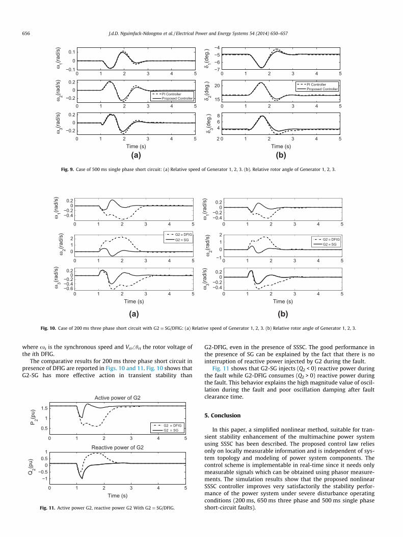
(b)Fig. 9. Case of 500 ms single phase short circuit: (a) Relative speed of Generator 1, 2, 3. (b). Relative rotor angle of Generator 1, 2, 3.
0 1 2 3 4 5
−0.4−0.2
00.2
ω1(ra
d/s)
0 1 2 3 4 5
012
ω2(ra
d/s)
0 1 2 3 4 5−0.6−0.4−0.2
00.2
ω3(ra
d/s)
Time (s)
G2 ≡ DFIGG2 ≡ SG
(a)
0 1 2 3 4 5−0.4−0.2
00.2
ω1(ra
d/s)
0 1 2 3 4 5−1
012
ω2(ra
d/s)
0 1 2 3 4 5−0.4−0.2
00.2
ω3(ra
d/s)
Time (s)
G2 ≡ DFIGG2 ≡ SG
(b)Fig. 10. Case of 200 ms three phase short circuit with G2 � SG/DFIG: (a) Relative speed of Generator 1, 2, 3. (b) Relative rotor angle of Generator 1, 2, 3.
656 J.d.D. Nguimfack-Ndongmo et al. / Electrical Power and Energy Systems 54 (2014) 650–657
where xs is the synchronous speed and Vri\hri the rotor voltage ofthe ith DFIG.
The comparative results for 200 ms three phase short circuit inpresence of DFIG are reported in Figs. 10 and 11. Fig. 10 shows thatG2-SG has more effective action in transient stability than
0 1 2 3 4 5
0.5
1
1.5
P 2(pu)
Active power of G2
0 1 2 3 4 5
−1−0.5
00.5
1
Q2(p
u)
Reactive power of G2
Time (s)
G2 ≡ DFIGG2 ≡ SG
Fig. 11. Active power G2, reactive power G2 With G2 � SG/DFIG.
G2-DFIG, even in the presence of SSSC. The good performance inthe presence of SG can be explained by the fact that there is nointerruption of reactive power injected by G2 during the fault.
Fig. 11 shows that G2-SG injects (Q2 < 0) reactive power duringthe fault while G2-DFIG consumes (Q2 > 0) reactive power duringthe fault. This behavior explains the high magnitude value of oscil-lation during the fault and poor oscillation damping after faultclearance time.
5. Conclusion
In this paper, a simplified nonlinear method, suitable for tran-sient stability enhancement of the multimachine power systemusing SSSC has been described. The proposed control law reliesonly on locally measurable information and is independent of sys-tem topology and modeling of power system components. Thecontrol scheme is implementable in real-time since it needs onlymeasurable signals which can be obtained using phasor measure-ments. The simulation results show that the proposed nonlinearSSSC controller improves very satisfactorily the stability perfor-mance of the power system under severe disturbance operatingconditions (200 ms, 650 ms three phase and 500 ms single phaseshort-circuit faults).
J.d.D. Nguimfack-Ndongmo et al. / Electrical Power and Energy Systems 54 (2014) 650–657 657
Appendix A. System data and observers/PI-regulator parameters
The Generators data and initial operating points are taking from[29,23]:
Parameter
Gen1 Gen2 Gen3
H (s)
23.64 6.40 3.01 Xd (pu) 0.1460 0.8958 1.3125 x0d (pu) 0.0608 0.1198 0.1813 D (pu) 0.3100 0.5305 0.6000 T 0d0 (s) 8.96 6.00 5.89 Pm (pu) 0.7157 1.6295 0.8502 dref (deg) 2.16 21.63 12.53 E0qref (pu) 1.0768 0.9833 1.0713
DFIG data are given as follows:
H (s)
Xd (pu) x0d (pu) D (pu)
6.40
0.8958 0.1198 0.5350 T 0d0 (s) dref (deg) E0qref (pu) ws (pu)
DC voltage regulator: KP = 5; KI = 10.Vq voltage regulator: KP = 0.1; KI = 9.
References
[1] Zangeneh A. A Lyapunov theory based UPFC controller for power flowcontroller. Electr Power Energy Syst 2009;31:302–8.
[2] Hingorani NG, Gyugyi L. Understanding FACTS concepts and technology offlexible AC transmission systems. New YorK: IEEE Press; 2000.
[3] Song Y, Johns T. Flexible AC transmission systems (FACTS). London: IEE; 2000.[4] Yazdani A, Iravani R. Voltage sourced converters in powers systems. New
Jersey: IEEE Press; 2010.[5] Panda S. Modeling, simulation and optimal tuning of SSSC-based controller in a
multimachine power system. World J Model Simulat 2010;6:110–21.[6] Thangavel M, Scholar P, Jasmine S. Enhancement of voltage stability and power
oscillation damping using static synchronous series compensator with smes.Int J Adv Res Technol 2012;2:94–8.
[7] Wang HF. Static synchronous series compensator to damp systemsoscillations. Electric Power Syst Res 2000;54:113–9.
[8] Menniti D, Pinnarelli A, Scordino N, Nicola S. Using a FACTS device controlledby a decentralized control law to damp the transient frequency deviation in aderegulated electric power system. Electric Power Syst Res 2004;72:289–98.
[9] Ngamroo I, Tippayachai J. Robust decentralised frequency stabilizers design ofstatic synchronous series compensators by taking system uncertainties intoconsideration. Electric Power Syst Res 2006;28:513–24.
[10] Castro MS, Ayres HM, Da Costa VF, Da Silva LPC. Impacts of the SSSC controlmodes on small-signal and transient stability of a power system. ElectricPower Syst Res 2007;77:1–9.
[11] Swain S, Mahapatra S, Panda S. Design of the optimized sssc based factscontroller. Int J Electron Electrical Eng 2012;2.
[12] Ghandhari M, Andersson G, Zanetta AI, Hiskens. Control Lyapunov functionsfor controllable series devices. IEEE Trans Power Syst 2001;16–4:689–94.
[13] Ghandhari M, Andersson G, Pavella M, Ernst D. A control strategy forcontrollable series capacitor in electric power systems. Automatica2001;37:1575–83.
[14] Haque MH. Determination of additional damping provided by a SSSC throughevaluation of rate dissipation of transient energy. In: 2004 InternationalConference on Power System Technology, (POWERCON’2004), vol. 2,Singapore; November 2004. p. 1942–1947.
[15] Haque MH. Damping improvement by facts devices: a comparison betweenstatcom and SSSC. Electric Power Syst Res 2006;76:865–72.
[16] Elkington K, Knazkins V, Ghandhari M. On the stability of power systemscontaining doubly fed induction generator-based generation. Electric PowerSyst Res 2008;78:1477–84.
[17] Jamali S, Shateri H. Locus of apparent impedance of distance protection in thepresence of SSSC. Eur Trans Electrical Power 2010;21:398–412.
[18] Wang H. Static synchronous series compensator to damp power systemoscillations. Electric Power Syst Res 2000;54:113–9.
[19] Xiao-Ping Z, Christian R, Biskash P. Flexible AC transmission systems:modelling and control. Germany: Springer; 2006.
[20] Dizdarevic N. Unified power flow controller in alleviation of voltage stabilityproblem, Ph.D. dissertation. University of Zagreb Faculty of ElectricalEngineering & Computing Department of Power Systems; 2001.
[21] Machowski J, Bialek J. State-variable control of shunt facts devices usingphasor measurements. Electric Power Syst Res 2008;78:39–48.
[22] Caldon R, Mattavelli P, Han BM. Dynamic analysis and control of UPFC usingtransient simulation. In: International conference on power systemstransients, Budapest, Hungary; 1999.
[23] Peter WS, Pai MA. Power system dynamics and stability. New Jersey: PrenticeHall; 1998.
[24] Pai MA. Energy function analysis for power system stability. Kluwer AcademicPublishers; 1989.
[25] Levant A. Robust exact differentiation via sliding mode technique. Automatica1998;34:379–84.
[26] Kenne G, Ahmed-Ali T, Lamnabhi-Lagarrigue F, Arzandé A. An improved rotorresistance estimator for induction motors adaptive control. Electric Power SystRes 2011;81:930–41.
[27] Radman G, Raje RS. Dynamic model for power systems with multiple FACTScontrollers. Electric Power Syst Res 2008;78:361–71.
[28] Kanchanaharuthai A, Chankong V, Loparo K. Small-signal stabilityenhancement of power systems with renewable energy resources. In:Preprints of the 18th IFAC world congress. Milano: International Federationof Automatic Control; 2011. p. 513–8.
[29] Colbia-Vegaa A, Leon-Morales JD, Fridman L, Salas-Pen O, Mata-Jimenez MT.Robust excitation control design using sliding-mode technique formultimachine power systems. Electric Power Syst Res 2008;78:1627–34.


![Optimal PSS Design in a Multimachine Power System via ... · Bacterial Foraging Optimization Algorithm (BFOA) as new optimization algorithm is discussed in [25] for optimal designing](https://static.documents.pub/doc/80x56/5f6a2786098afa445e036d8b/optimal-pss-design-in-a-multimachine-power-system-via-bacterial-foraging-optimization.jpg)
