34
Electrical Safety Applications in PV Installations John Shober CSP, CHMM
| Date post: | 10-Apr-2018 |
| Category: |
Documents |
| Upload: | duongkhanh |
| View: | 220 times |
| Download: | 3 times |

Electrical Safety Applications in PV Installations
John Shober CSP, CHMM

Overview
• Solar Cell Primer
• What is an Array?
• PV Differences
• PV Integration & Growth
• Systems Integration
• Electrical Hazards
• Injury Pathology
• Clearance Distances
• Labeling
• Common Electrical Safety Concerns
Solar Cell Primer
• ~90% of current PV is based on silicon technology.
• Silicon Product Types:• Monocrystalline silicon (mono-Si)/(single-crystal-Si)
• Easily recognizable, uniform look/dark color
• 15-20% efficiency
• Polycrystalline silicon - polysilicon (p-Si), multi-crystalline silicon (mc-Si), introduced 1981.
• 13-16% efficiency
• String Ribbon panels based on polycrystalline silicon.
• 13-14% efficiency

Solar Cell Primer
• Thin-film photovoltaic cells (TFPV) include:• Amorphous silicon (a-Si)
• Cadmium telluride (CdTe)
• Copper indium gallium selenide (CIS/CIGS)
• Organic photovoltaic cells (OPC)
• 1+ layer deposition of photovoltaic material onto a substrate.
Solar Cell Primer
• A module is a collection of PV cells connected in series and/or parallel.
• Cells are incorporated into an environmentally protective laminate. Example:• ~0.5 volt/cell
• 36 cells connected together produce enough energy to charge 12 volt batteries and run pumps and motors
• 72-cell modules (standard for utility systems) have a nominal 24V operating at ~30V.

What is a PV Array?
• Home use system can contain 10-20 modules.
• Mounted at a fixed azimuth (South facing) or implemented with a sun position tracking device.
• Multiple modules integrated together to create an array.
• Industrial/Utility applications incorporate numerous modules (sometimes hundreds) into an array.
• Utilities can incorporate a large number of arrays to produce required voltages.

PV Differences
• DC circuits requiring novel design and equipment.
• May have multiple energy sources, incorporate unique disconnects required to isolate components.
• Energy flows can be bi-directional.
• Utility-Interactive arrays will be required to interface with AC utility grid requirements and may need unique operational requirements. • May require considerations not realized in normal grid systems.

Systems Integration
• Price ($/W DC)/Installed• Residential
• 2011 - $6.00
• 2013 - $~4.75
• Business• 2011 - $5.00
• 2013 - $4.60
• Utylity• 2011 - $3.50
• 2013 - $2.00850
1915
3364
4546
2010 2011 2012 2013
Installation (MW DC)
Installed

Systems Integration
• US Electrical Generation Capacity in beginning of 2014:• Geothermal 1%
• Natural gas 4%
• Wind 20%
• Solar 74%
• Other ~1%

Basic PV Components
Combiner
PV Source Circuits
PV Output
Invertor Input
Invertor
Invertor Output
Production &
Distribution
Connection
Interactive System

Basic PV Components
Main
Supply AC
Change
Controller
PV Output
Invertor Input
Invertor
Invertor Output
Main Supply
DCEnergy Storage
Invertor
Stand-Alone System

Electrical Safety Control
• Engineer out the hazard• If normal maintenance must occur then engineer out the potential.
• Positive effect on controlling Arc Flash Hazard.
• Administrative controls• Safe Work Practices
• Rated Equipment and Tooling
• PPE• Voltage Rated
• <=600 V Nominal industry best practice is 1000V rated gloves.
• PPE rated for Arc Flash Category

Vector of Exposure: Injury
Electrical Exposures (NSC)
Exposures/yr. Fatalities/yr.
30,000
• Electrocution (Fatality)
• Electrical Shock
• Burns600
CURRENT
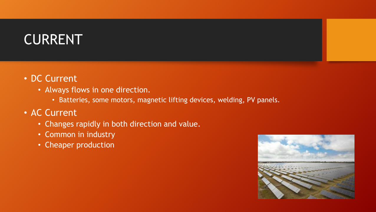
• DC Current• Always flows in one direction.
• Batteries, some motors, magnetic lifting devices, welding, PV panels.
• AC Current• Changes rapidly in both direction and value.
• Common in industry
• Cheaper production

Vector of Exposure: Elements
E=I x R
E= Voltage
I= Amperage
R = Resistance
Amount (E & I)
Duration
Path

Vector of Exposure: Resistance
Resistance
• Impedes or Increases Exposure Potential
Wet
• Dramatically Lowers Resistance
Dry
• Dramatically Increases Resistance
Effects of AC Electricity
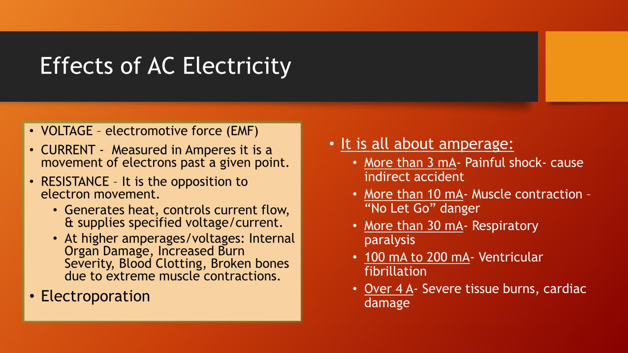
• It is all about amperage:• More than 3 mA- Painful shock- cause
indirect accident
• More than 10 mA- Muscle contraction –“No Let Go” danger
• More than 30 mA- Respiratory paralysis
• 100 mA to 200 mA- Ventricular fibrillation
• Over 4 A- Severe tissue burns, cardiac damage
• VOLTAGE – electromotive force (EMF)
• CURRENT - Measured in Amperes it is a movement of electrons past a given point.
• RESISTANCE – It is the opposition to electron movement.
• Generates heat, controls current flow, & supplies specified voltage/current.
• At higher amperages/voltages: Internal Organ Damage, Increased Burn Severity, Blood Clotting, Broken bones due to extreme muscle contractions.
• Electroporation

Vector of Exposure: Potential
Path through body
Touch Potential Similar to a
voltage drop with shorter distance and higher current potential.
Step Potential

Injury Pathology: Burns
• Can be multi-modal:
• Equipment Thermal Exposure
• Electrical Exposure
• Arc
• High Temperature Plasma Arc
Electrical
Arc
Thermal Contact
Heat Transfer:
• Conductive (Geometry of Contact)
• Convective (Respiratory & Dermal)
• Radiative
Rule of Nines

Injury Pathology: Arc
Arc Pressure Wave
Sound WaveShrapnel/Molten
Metal
• Plasma Arc = 35,000F• Fatal Burns at >10 feet
• 1.2 calories/cm2 will induce a recoverable 2nd degree burn
Temperature 2nd Degree
Burn
3rd Degree Burn
122 F 1 Minute 5 Minutes
140 F 2 Seconds 5 Seconds
149 F <1 Second 2 Seconds
• Copper expands >67,000 (Water ~1.67K)• One cubic inch of copper expands to 1.44 cubic yards of
vaporized copper.
• Arc Blast Pressure levels can reach levels in excess of 400 lbs./ft3
• Sound Pressure levels can reach 140dB.

PV Systems and Rated Equipment
• Not a constant voltage source, there can be significant differences between rated operating voltage and field open voltage conditions.
• Higher performance with lower temperatures.
• Bipolar System (Positive and Negative Voltages) must sum absolute values to determine the rated open circuit voltage.
• Temperature Dependent Factors
• 125% factor needed due to PV module output currents that can exceed rated short circuit currents near solar noon.
• DC fault currents are harder to interrupt. Devices listed only for AC should not be used.
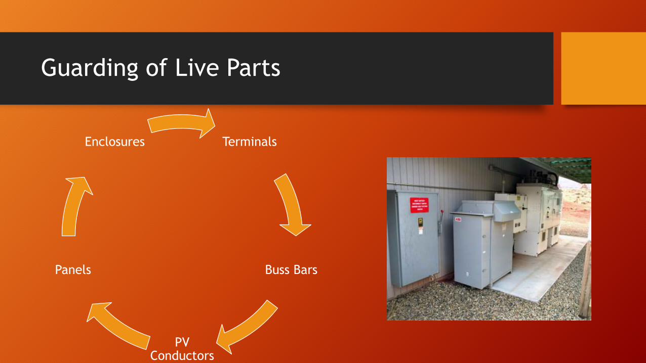
Guarding of Live Parts
Terminals
Buss Bars
PV Conductors
Panels
Enclosures
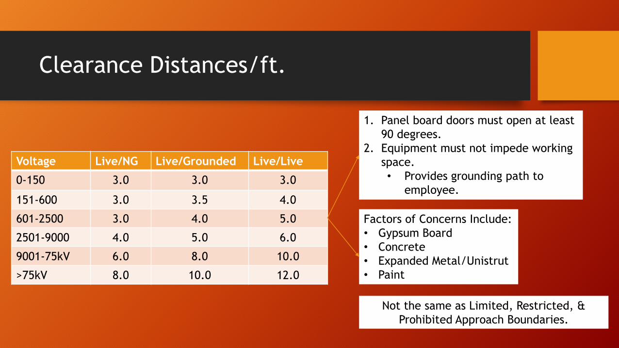
Clearance Distances/ft.
Voltage Live/NG Live/Grounded Live/Live
0-150 3.0 3.0 3.0
151-600 3.0 3.5 4.0
601-2500 3.0 4.0 5.0
2501-9000 4.0 5.0 6.0
9001-75kV 6.0 8.0 10.0
>75kV 8.0 10.0 12.0
Factors of Concerns Include:
• Gypsum Board
• Concrete
• Expanded Metal/Unistrut
• Paint
1. Panel board doors must open at least
90 degrees.
2. Equipment must not impede working
space.
• Provides grounding path to
employee.
Not the same as Limited, Restricted, &
Prohibited Approach Boundaries.

Clearance Distances
• Working distance width shall be the width of the equipment or 30”, whichever is greater.
• Height to extend from grade or floor to a height of 6.5 feet or the height of the equipment (if greater).
61/2’
min
30” min

PV Incident Energy
• PV systems can have significant Fault Current.
• Resistance can impede Over Current Protection Device Trip Time.
• There may be variation in power production driven by weather, time of day, etc.
• Cracked panel can provide direct exposure access
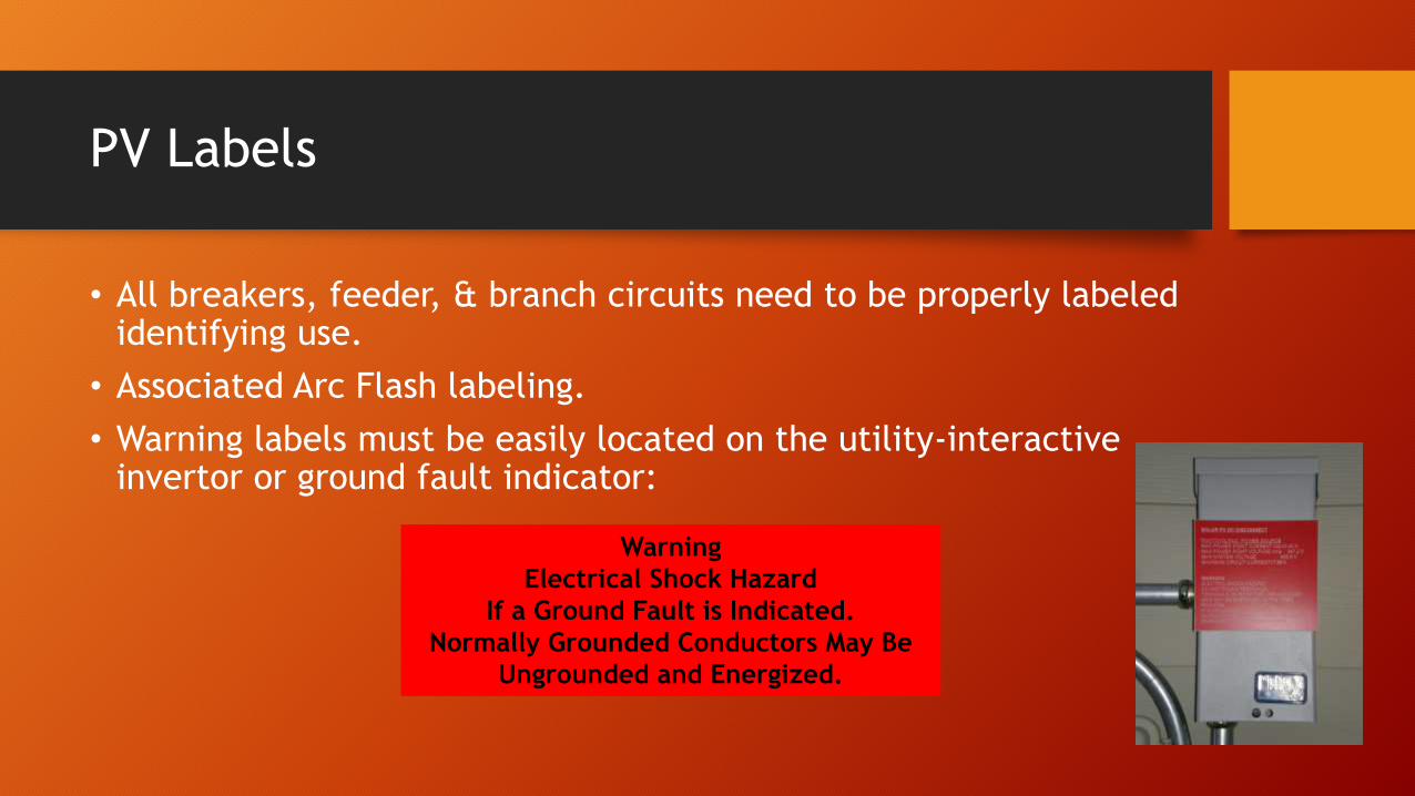
PV Labels
• All breakers, feeder, & branch circuits need to be properly labeled identifying use.
• Associated Arc Flash labeling.
• Warning labels must be easily located on the utility-interactive invertor or ground fault indicator:
Warning
Electrical Shock Hazard
If a Ground Fault is Indicated.
Normally Grounded Conductors May Be
Ungrounded and Energized.

PV Labels
• Bipolar Source & Output Circuits:
• Single 120V Supply
Warning
Bipolar Photovoltaic Array.
Disconnection of Neutral or Grounded
Conductors May Result in Overvoltage in
Array or Invertor.
Warning
Single 120-Volt Supply. Do Not Connect
Multiwire Branch Circuits!

PV Labels
• Building or Structure Disconnecting Means:
• PV Power Source Conductors:
Warning
Electric Shock Hazard
Do Not Touch Terminals.
Terminals on Both The Line
And Load Sides May Be Energized
In the Open Position.
Warning: Photovoltaic Power Source

PV Labels
• Junction Boxes, Combiners, Disconnects, and devices with energized or ungrounded conductors that may be exposed during maintenance or testing activities:
Warning
Electric Shock Hazard. The DC
Conductors Of This Photovoltaic System
Are Ungrounded And May Be Energized.

Common Electrical Safety Issues:
• Limited Personnel in Remote Areas
• Communication
• Buddy System
• First Aid/PPE, etc.
• UV Degradation
• Environmental Impact
• Rain, Snow, Freezing Temperatures
• Cord Damage
• Unguarded Parts
• Loose Terminals

Common Electrical Safety Issues:
• Improperly Placed Equipment Infringing on Clearance Distances
• Buss Shunting/Fault Condition
• Grounding
• Securing PV Conductors
• Cracked Panels
• Just because it is cracked doesn’t mean that electrical energy is not present?
• Water can be a significant exposure issue!

References:
• Medscape:
http://emedicine.medscape.com/article/770179-overview#a0104
• The Merk Manual:
http://www.merckmanuals.com/professional/injuries_poisoning/electrical_and_lightning_injuries/electrical_injuries.html
• CDC:
http://www.cdc.gov/niosh/topics/electrical/
• Solar Energy Industries Association
http://www.seia.org/
• OSHA 1910 Subpart S:
https://www.osha.gov/pls/oshaweb/owadisp.show_document?p_table=STANDARDS&p_id=10135
• NFPA 70 (Installation/Design)
http://www.nfpa.org/codes-and-standards/document-information-pages?mode=code&code=70

References:
• NESC (Worker Training)
http://standards.ieee.org/about/nesc/
• IEEE 1584-2 (Design)
http://www.ieee1584.com/
• ANSI Z244 (Energy Control)
http://webstore.ansi.org/RecordDetail.aspx?sku=ANSI%2fASSE+Z244.1-2003+(R2008)
• NFPA 70B (Maintenance Practices)
http://www.nfpa.org/codes-and-standards/document-information-pages?mode=code&code=70B
• NFPA 70E (Safe Work Practices)
http://www.nfpa.org/catalog/category.asp?category_name=NFPA%2070E
• NFPA 79 (Install/Design)
http://www.nfpa.org/codes-and-standards/document-information-pages?mode=code&code=79
Questions?


