44
Born in the lab to outlast in the field X-Tract ® Electrical Submersible Pump Cable JANUARY 2013

Born in the lab to outlast inthe field
X-Tract®
Electrical Submersible Pump Cable
J A N UA R Y 2 013

WELCOME
Contact Us
On-Line Catalog Features
•Viewthecataloginfullscreenmodebyusingthefarleftexpansionlogoonthemenubar.(Keyboardinputmaynotworkinfullscreenmode,whichmeansyoumustleavethefullscreenmodeinordertoutilizetheemailfunction.)
•Clickthe“GeneralCable”logoontheleftsideofthemenubartogotoGeneralCable’sWebsite.
•The“TableofContents”buttoninthecenterofthemenubartakesyoutoafullyinteractivepage.Clickonanyproductcategoryorlistingtotakeyoutotheappropriatepage.(Allotherpagereferencesthroughoutthecatalogarealsofullyinteractive.)
•Theentirecatalog’scontentscanbesearchedusingtheSearchbuttonlocatedintheupperrightofthemenubar.
•Turncatalogpagesbyclickingyourmouseonthetoporbottomcornerofthepageorbyusingtheforwardorbackarrowsonthesideofthepageoronthebottombar.
•Zoomtodetailsoneachpagebyclickingwhenthemagnifyingglasspointerisactive.Clickagaintoreturntofullview.
•Sharethecompleteinteractivecatalogbyselectingthe“SharethisPublication”iconlocatedinthelowerrightonthebottombar.
•PrintallorselectedpagesusingthePrinticonlocatedinthelowerrightonthebottombar.
•TheentireinteractivecatalogorindividualpagescanbedownloadedasaPDFusingthePDFiconlocatedinthelowerrightonthebottombar.
•Use“Croppartofpage”iconlocatedinthelowerrightonthebottombartotakeasnapshotofanypartofapageandsaveasajpg.
General Cable Website
Join the Wire Wizard for a quick, informative tour showing the interactive features of our catalogs
X-Tract®
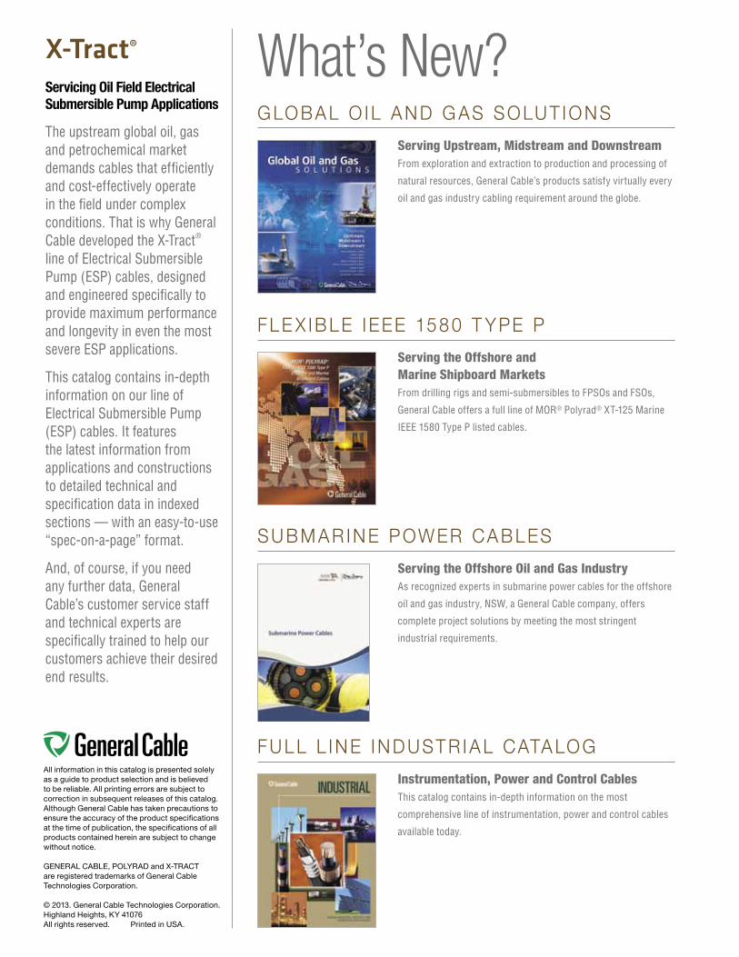
Servicing Oil Field Electrical Submersible Pump Applications
The upstream global oil, gas and petrochemical market demands cables that efficiently and cost-effectively operate in the field under complex conditions. That is why General Cable developed the X-Tract® line of Electrical Submersible Pump (ESP) cables, designed and engineered specifically to provide maximum performance and longevity in even the most severe ESP applications.
This catalog contains in-depth information on our line of Electrical Submersible Pump (ESP) cables. It features the latest information from applications and constructions to detailed technical and specification data in indexed sections — with an easy-to-use “spec-on-a-page” format.
And, of course, if you need any further data, General Cable’s customer service staff and technical experts are specifically trained to help our customers achieve their desired end results.
All information in this catalog is presented solely as a guide to product selection and is believed to be reliable. All printing errors are subject to correction in subsequent releases of this catalog. Although General Cable has taken precautions to ensure the accuracy of the product specifications at the time of publication, the specifications of all products contained herein are subject to change without notice.
GENERAL CABLE, POLYRAD and X-TRACT are registered trademarks of General Cable Technologies Corporation.
© 2013. General Cable Technologies Corporation.Highland Heights, KY 41076All rights reserved. Printed in USA.
What’s New? G LO B A L O I L A N D G AS SO LU T I O N S
Serving Upstream, Midstream and DownstreamFrom exploration and extraction to production and processing of
natural resources, General Cable’s products satisfy virtually every
oil and gas industry cabling requirement around the globe.
F L E X I B L E I EEE 15 8 0 T Y PE P
Serving the Offshore and Marine Shipboard MarketsFrom drilling rigs and semi-submersibles to FPSOs and FSOs,
General Cable offers a full line of MOR® Polyrad® XT-125 Marine
IEEE 1580 Type P listed cables.
S U B M A R I N E P OW ER CA B L ES
Serving the Offshore Oil and Gas IndustryAs recognized experts in submarine power cables for the offshore
oil and gas industry, NSW, a General Cable company, offers
complete project solutions by meeting the most stringent
industrial requirements.
F U L L L I N E I N D U ST R I A L CATA LO G
Instrumentation, Power and Control CablesThis catalog contains in-depth information on the most
comprehensive line of instrumentation, power and control cables
available today.
X-Tract®
Electrical Submersible Pump (ESP) Cable
Participation in the global oil, gas and petrochemical (OGP) market sector is an important part of General Cable’s long-term energy strategy.
General Cable has positioned itself globally as an “energy company” and is making major investments in wire and cable products for the energy infrastructure markets. With oil and gas as a primary driver of energy, General Cable has listened to customers and analyzed its product offering based on market input. Consequently, it is rounding out its portfolio of products on a global scale, adding X-Tract® (Electrical Submersible Pump Cable), CCW (Continuously Corrugated Welded Cable), umbilical, and subsea cables to a suite of products used by the oil, gas and petrochemical industries for power, control, instrumentation, and communications.
The introduction of the X-Tract® Electrical Submersible Pump (ESP) product line expands General Cable’s current OGP product offering, providing existing and new customers with a single source for their wire and cable needs, while at the same time allowing General Cable to participate more broadly in the upstream segment of the OGP market, which includes onshore and offshore oil and gas exploration and production.
X-Tract® cables are specifically engineered for longevity, offering the highest degree of reliability in the sweetest to the most sour wells, even in high-temperature and severe-corrosion environments. They are offered in both round and flat constructions with varying designs adapted to different well environments, based on temperature, corrosion and pressure-resistance needs. All designs reference IEEE 1018, IEEE 1019 and all subordinate specifications.
General Cable is committed to maintaining an adequate level of inventory to assure maximum availability for customers.

Our Green Initiative symbol recognizes our role
and responsibility in promoting sustainability.
The symbol also reflects our commitment to achieving
industry-leading standards and responding
proactively to environmental global issues.
Visit www.generalcable.comSelect “COMPANY”, then select “Corporate Social Responsibility”
Building Bridges in the Sky
Making Contact with the World
Directing Traffic without Gridlock
General Cable is a leader in the
development, design, manufacture,
marketing and distribution of copper,
aluminum and fiber optic wire and cable
for the energy, industrial, specialty and
communications markets.
Our products inspire progress worldwide …
customers use our value-added products
to create global infrastructure that
improves the standard of living for
people everywhere.
Each day we’re building business
momentum — developing ideas into
innovative solutions and industry-leading
products, expanding geographic access and
furthering our investment in highly capable
associates, Lean Manufacturing, material
science and technology resources.
General Cable is influencing the world … with more than two-thirds
of our sales generated outside North America, 14,000 associates
worldwide and 57 manufacturing facilities throughout 26 countries.
As one of the largest wire and cable manufacturers, we are the
One Company Connecting the World.
Energy Cables Our cables carry energy across the world — through the air,
underground and under the sea. Increasing demand for energy is
accelerating investment in exploration, extraction, power generation,
transmission and distribution — whether based on coal, natural gas,
oil, nuclear, wind, solar or water.
Industrial & Specialty Cables Our cables channel the power and signals that make equipment hum
and engines run. From oil rigs and broadcast studios to cars and trains,
and in commercial buildings, public venues, factory floors and special
applications such as military, nuclear, marine and mining — we serve
an extensive range of markets.
Communications Cables Our cables keep information flowing — facilitating a non-stop stream
of words and images around the world. We meet the high-speed
bandwidth needs of global communications networks, from fiber
optic submarine communications cables, copper and fiber aerial and
underground cables to copper and fiber optic enterprise cables and
system solutions.
World Headquarters General Cable 4 Tesseneer Drive
Highland Heights, KY
41076-9753 U.S.A.
1
Phone: 866-248-7060www.generalcable.com
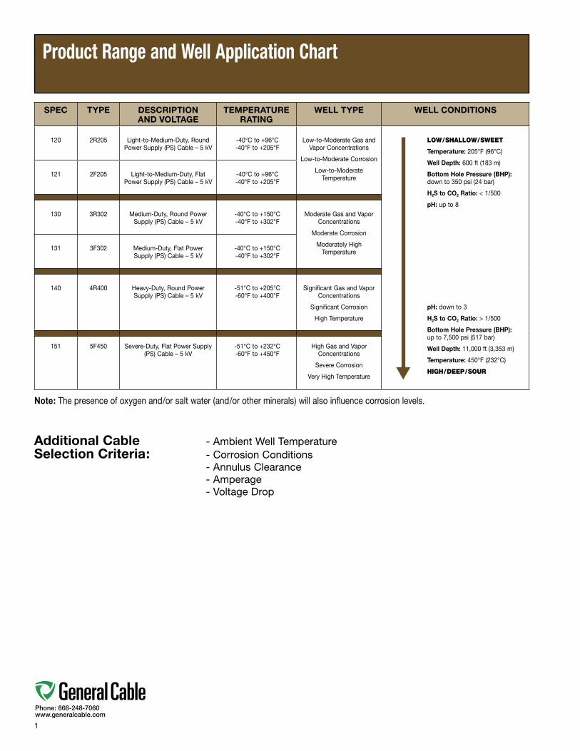
Product Range and Well Application Chart
Additional Cable - Ambient Well TemperatureSelection Criteria: - Corrosion Conditions - Annulus Clearance - Amperage - Voltage Drop
SPEC TYPE DESCRIPTION AND VOLTAGE
TEMPERATURE RATING
WELL TYPE WELL CONDITIONS
120 2R205 Light-to-Medium-Duty, Round Power Supply (PS) Cable – 5 kV
-40°C to +96°C-40°F to +205°F
Low-to-Moderate Gas and Vapor Concentrations
Low-to-Moderate Corrosion
Low-to-Moderate Temperature
LOW/SHALLOW/SWEET
Temperature: 205°F (96°C)
Well Depth: 600 ft (183 m)
Bottom Hole Pressure (BHP): down to 350 psi (24 bar)
H2S to CO2 Ratio: < 1/500
pH: up to 8
pH: down to 3
H2S to CO2 Ratio: > 1/500
Bottom Hole Pressure (BHP): up to 7,500 psi (517 bar)
Well Depth: 11,000 ft (3,353 m)
Temperature: 450°F (232°C)
HIGH/DEEP/SOUR
121 2F205 Light-to-Medium-Duty, Flat Power Supply (PS) Cable – 5 kV
-40°C to +96°C-40°F to +205°F
130 3R302 Medium-Duty, Round Power Supply (PS) Cable – 5 kV
-40°C to +150°C-40°F to +302°F
Moderate Gas and Vapor Concentrations
Moderate Corrosion
Moderately High Temperature131 3F302 Medium-Duty, Flat Power
Supply (PS) Cable – 5 kV-40°C to +150°C-40°F to +302°F
140 4R400 Heavy-Duty, Round Power Supply (PS) Cable – 5 kV
-51°C to +205°C-60°F to +400°F
Significant Gas and Vapor Concentrations
Significant Corrosion
High Temperature
151 5F450 Severe-Duty, Flat Power Supply (PS) Cable – 5 kV
-51°C to +232°C-60°F to +450°F
High Gas and Vapor Concentrations
Severe Corrosion
Very High Temperature
Note: The presence of oxygen and/or salt water (and/or other minerals) will also influence corrosion levels.
2
Phone: 866-248-7060www.generalcable.com
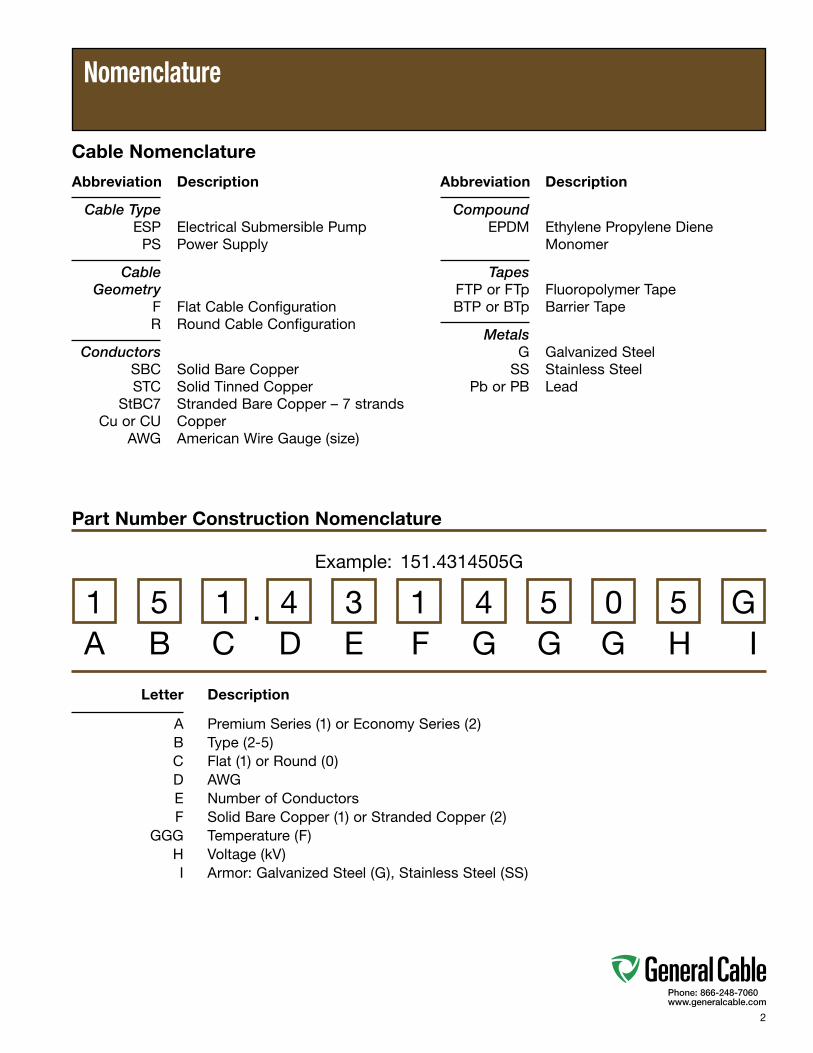
Abbreviation Description
Cable Type ESP Electrical Submersible Pump PS Power Supply
Cable Geometry F Flat Cable Configuration R Round Cable Configuration
Conductors SBC Solid Bare Copper STC Solid Tinned Copper StBC7 Stranded Bare Copper – 7 strands Cu or CU Copper AWG American Wire Gauge (size)
Letter Description
A Premium Series (1) or Economy Series (2) B Type (2-5) C Flat (1) or Round (0) D AWG E Number of Conductors F Solid Bare Copper (1) or Stranded Copper (2) GGG Temperature (F) H Voltage (kV) I Armor: Galvanized Steel (G), Stainless Steel (SS)
Abbreviation Description
Compound EPDM Ethylene Propylene Diene Monomer
Tapes FTP or FTp Fluoropolymer Tape BTP or BTp Barrier Tape
Metals G Galvanized Steel SS Stainless Steel Pb or PB Lead
Nomenclature
Example: 151.4314505G
A B C D E F G G G H I1 5 1 4 3 1 4 5 0 5 G
Part Number Construction Nomenclature
Cable Nomenclature
.

3
Phone: 866-248-7060www.generalcable.com
Date of Issue 1/13Section 1 Electrical Submersible Pump Cables
Table of Contents
X-Tract® Electrical Submersible Pump Cable for Oil FieldsSPECIFICATION NO. PRODUCT DESCRIPTION REVISION DATE PAGE
120 X-Tract® 2R205 Light-to-Moderate-Duty, Round Power Supply (PS) Cable Jan. 2013 5-6 ESP 5 kV, Rated -40°C to +96°C/-40°F to +205°F
121 X-Tract® 2F205 Light-to-Moderate-Duty, Flat Power Supply (PS) Cable Jan. 2013 7-8 ESP 5 kV, Rated -40°C to +96°C/-40°F to +205°F
130 X-Tract® 3R302 Moderate-Duty, Round Power Supply (PS) Cable Jan. 2013 9-10 ESP 5 kV, Rated -40°C to +150°C/-40°F to +302°F
131 X-Tract® 3F302 Moderate-Duty, Flat Power Supply (PS) Cable Jan. 2013 11-12 ESP 5 kV, Rated -40°C to +150°C/-40°F to +302°F
140 X-Tract® 4R400 Heavy-Duty, Round Power Supply (PS) Cable Jan. 2013 13-14 ESP 5 kV, Rated -51°C to +205°C/-60°F to +400°F
151 X-Tract® 5F450 Severe-Duty, Flat Power Supply (PS) Cable Jan. 2013 15-16 ESP 5 kV, Rated -51°C to +232°C/-60°F to +450°F

4
Phone: 866-248-7060www.generalcable.com
Date of Issue 1/13Electrical Submersible Pump Cables Section 2
Table of Contents
Technical Information SPECIFICATION DESCRIPTION REVISION DATE PAGE
Technical Table of Contents Jan. 2013 17
Technical Recommended Installation Practice Jan. 2013 18-27
Technical Testing Jan. 2013 28-29
H005 Voltage Drop and Ampacity Calculation Jan. 2013 30-33
A018 ESP Cable Cross-Reference Jan. 2013 34
A150 Metric Conversion Factors Sept. 2010 35
A185 AWG (American Wire Gauge) to mm2 (Millimeters Squared) Conversion Sept. 2010 36
Index Part Number Index Jan. 2013 37
5
Phone: 866-248-7060www.generalcable.com
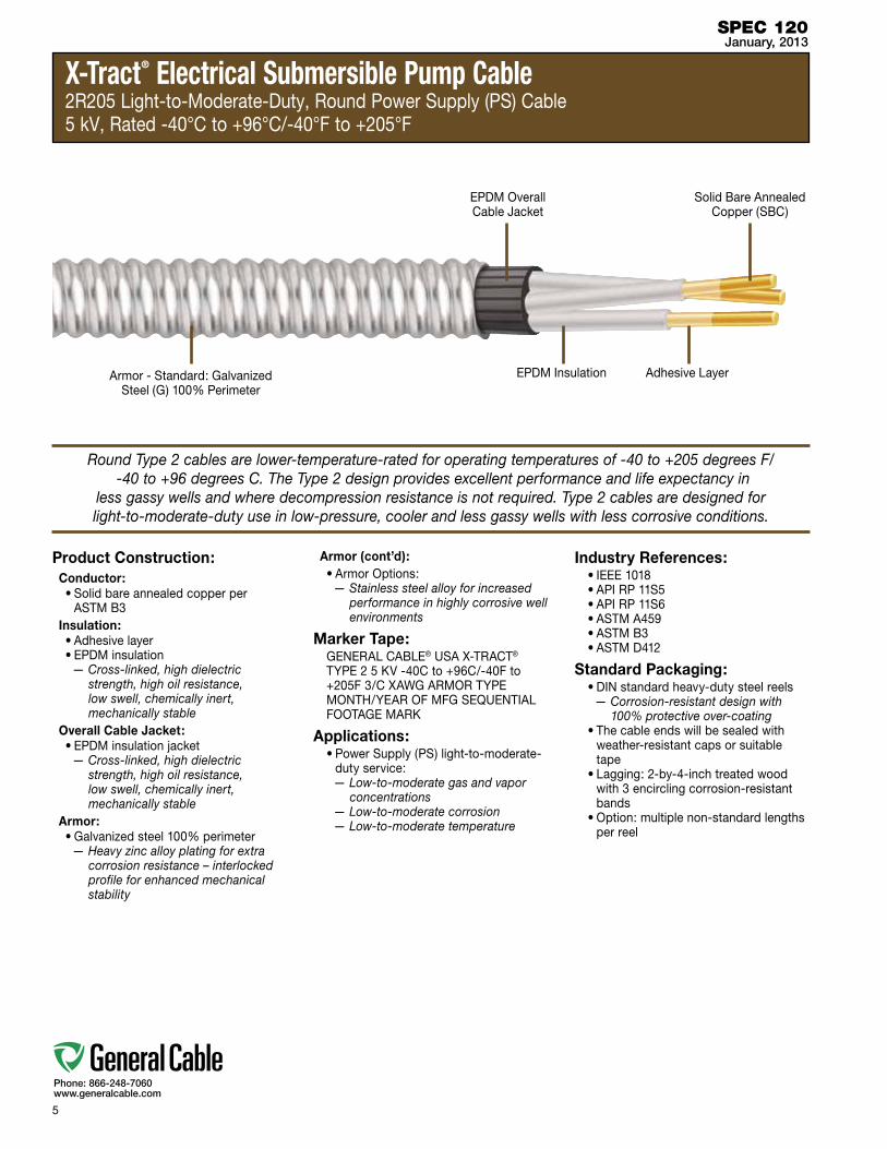
X-Tract® Electrical Submersible Pump Cable2R205 Light-to-Moderate-Duty, Round Power Supply (PS) Cable5 kV, Rated -40°C to +96°C/-40°F to +205°F
Product Construction:Conductor:•Solidbareannealedcopperper
ASTM B3Insulation:•Adhesivelayer•EPDMinsulation
— Cross-linked, high dielectric strength, high oil resistance, low swell, chemically inert, mechanically stable
Overall Cable Jacket:•EPDMinsulationjacket
— Cross-linked, high dielectric strength, high oil resistance, low swell, chemically inert, mechanically stable
Armor:•Galvanizedsteel100%perimeter
— Heavy zinc alloy plating for extra corrosion resistance – interlocked profile for enhanced mechanical stability
Armor (cont’d):•ArmorOptions:
— Stainless steel alloy for increased performance in highly corrosive well environments
Marker Tape:GENERAL CABLE® USA X-TRACT® TYPE 2 5 KV -40C to +96C/-40F to +205F 3/C XAWG ARMOR TYPE MONTH/YEAR OF MFG SEQUENTIAL FOOTAGE MARK
Applications:•PowerSupply(PS)light-to-moderate-
duty service:— Low-to-moderate gas and vapor
concentrations— Low-to-moderate corrosion— Low-to-moderate temperature
Industry References:•IEEE1018•APIRP11S5•APIRP11S6•ASTMA459•ASTMB3•ASTMD412
Standard Packaging:•DINstandardheavy-dutysteelreels
— Corrosion-resistant design with 100% protective over-coating
•Thecableendswillbesealedwithweather-resistant caps or suitable tape
•Lagging:2-by-4-inchtreatedwoodwith 3 encircling corrosion-resistant bands
•Option:multiplenon-standardlengthsper reel
SPEC 120January, 2013
Round Type 2 cables are lower-temperature-rated for operating temperatures of -40 to +205 degrees F/ -40 to +96 degrees C. The Type 2 design provides excellent performance and life expectancy in
less gassy wells and where decompression resistance is not required. Type 2 cables are designed for light-to-moderate-duty use in low-pressure, cooler and less gassy wells with less corrosive conditions.
EPDM Insulation Adhesive Layer
Solid Bare Annealed Copper (SBC)
Armor - Standard: Galvanized Steel(G)100%Perimeter
EPDM Overall Cable Jacket

6
Phone: 866-248-7060www.generalcable.com
X-Tract® Electrical Submersible Pump Cable2R205 Light-to-Moderate-Duty, Round Power Supply (PS) Cable5 kV, Rated -40°C to +96°C/-40°F to +205°F
SPEC 120January, 2013
PARTNUMBER kV
COND. SIZE (Solid)
NOMINAL CONDUCTOR DIAMETER
NOMINAL INSULATION DIAMETER
NOMINAL JACKET DIAMETER
ARMOR TYPE
NOMINAL CABLE O.D. NOMINAL WEIGHT
AWG mm² INCHES mm INCHES mm INCHES mm INCHES mm LBS/1000 fT kg/km
120.6312055G 5 6 13.30 0.162 4.11 0.342 8.69 0.857 21.77 Galvanized Steel (G) 1.10 27.86 959 1427
120.6312055SS 5 6 13.30 0.162 4.11 0.342 8.69 0.857 21.77 Stainless Steel (SS) 1.02 25.83 815 1213
120.5312055G 5 5 16.78 0.182 4.62 0.362 9.19 0.900 22.86 Galvanized Steel (G) 1.14 28.95 1078 1604
120.5312055SS 5 5 16.78 0.182 4.62 0.362 9.19 0.900 22.86 Stainless Steel (SS) 1.06 26.92 926 1378
120.4312055G 5 4 21.15 0.204 5.19 0.384 9.76 0.948 24.08 Galvanized Steel (G) 1.19 30.18 1204 1792
120.4312055SS 5 4 21.15 0.204 5.19 0.384 9.76 0.948 24.08 Stainless Steel (SS) 1.11 28.15 1045 1555
120.2312055G 5 2 33.63 0.258 6.54 0.438 11.12 1.063 27.00 Galvanized Steel (G) 1.30 33.10 1543 2295
120.2312055SS 5 2 33.63 0.258 6.54 0.438 11.12 1.063 27.00 Stainless Steel (SS) 1.22 31.06 1364 2029
120.1312055G 5 1 42.34 0.289 7.35 0.469 11.92 1.131 28.74 Galvanized Steel (G) 1.37 34.83 1769 2632
120.1312055SS 5 1 42.34 0.289 7.35 0.469 11.92 1.131 28.74 Stainless Steel (SS) 1.29 32.80 1578 2348
Voltagedropbasedon60Hzand100%powerfactor

7
Phone: 866-248-7060www.generalcable.com
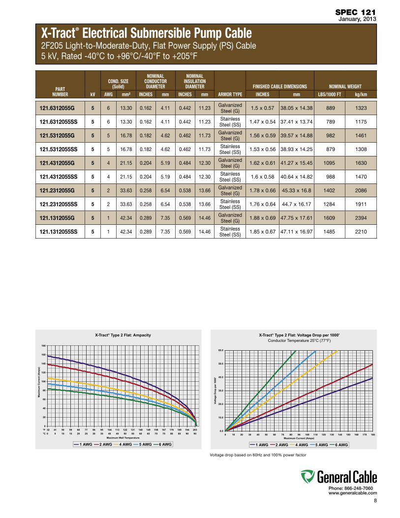
X-Tract® Electrical Submersible Pump Cable2F205 Light-to-Moderate-Duty, Flat Power Supply (PS) Cable5 kV, Rated -40°C to +96°C/-40°F to +205°F
Product Construction:Conductor:•Solidbareannealedcopperper
ASTM B3Insulation:•Adhesivelayer•EPDMinsulation
— Cross-linked, high dielectric strength, high oil resistance, low swell, chemically inert, mechanically stable
•EPDMinsulationjacket— Cross-linked, high dielectric
strength, high oil resistance, low swell, chemically inert, mechanically stable
Barrier:•Barriertape–wovenfabric,rubber-
impregnated, helically wrapped— Stress-distributing, mechanically
stable
Armor:•Galvanizedsteel100%perimeter
— Heavy zinc alloy plating for extra corrosion resistance – interlocked profile for enhanced mechanical stability
•ArmorOptions:— Stainless steel alloy for increased
performance in highly corrosive well environments
Marker Tape:GENERAL CABLE® USA X-TRACT® TYPE 2 5 KV -40C to +96C/-40F to +205F 3/C XAWG ARMOR TYPE MONTH/YEAR OF MFG SEQUENTIAL FOOTAGE MARK
Applications:•PowerSupply(PS)light-to-moderate-
duty service:— Low-to-moderate gas and vapor
concentrations— Low-to-moderate corrosion— Low-to-moderate temperature
Industry References:•IEEE1018•APIRP11S5•APIRP11S6•ASTMA459•ASTMB3•ASTMD412
Standard Packaging:•DINstandardheavy-dutysteelreels
— Corrosion-resistant design with 100% protective over-coating
•Thecableendswillbesealedwithweather-resistant caps or suitable tape
•Lagging:2-by-4-inchtreatedwoodwith 3 encircling corrosion-resistant bands
•Option:multiplenon-standardlengthsper reel
SPEC 121January, 2013
Flat Type 2 cables are lower-temperature-rated for operating temperatures of -40 to +96 degrees C/ -40 to +205 degrees F. The Type 2 design provides excellent performance and life expectancy in less
gassy wells and where decompression resistance is not required. Type 2 cables are designed for light-to-moderate-duty use in low-pressure, cooler and less gassy wells with less corrosive conditions.
EPDM Insulation Jacket
EPDM Insulation
Adhesive Layer
Solid Bare Annealed Copper (SBC)
Armor - Standard: Galvanized Steel(G)100%Perimeter
Barrier Tape (BTP) – Woven Fabric, Rubber-Impregnated, Helically Wrapped
8
Phone: 866-248-7060www.generalcable.com
X-Tract® Electrical Submersible Pump Cable2F205 Light-to-Moderate-Duty, Flat Power Supply (PS) Cable5 kV, Rated -40°C to +96°C/-40°F to +205°F
SPEC 121January, 2013
PARTNUMBER kV
COND. SIZE (Solid)
NOMINAL CONDUCTOR DIAMETER
NOMINAL INSULATION DIAMETER
ARMOR TYPE
fINISHED CABLE DIMENSIONS NOMINAL WEIGHT
AWG mm² INCHES mm INCHES mm INCHES mm LBS/1000 fT kg/km
121.6312055G 5 6 13.30 0.162 4.11 0.442 11.23 Galvanized Steel (G) 1.5 x 0.57 38.05 x 14.38 889 1323
121.6312055SS 5 6 13.30 0.162 4.11 0.442 11.23 Stainless Steel (SS) 1.47 x 0.54 37.41 x 13.74 789 1175
121.5312055G 5 5 16.78 0.182 4.62 0.462 11.73 Galvanized Steel (G) 1.56 x 0.59 39.57 x 14.88 982 1461
121.5312055SS 5 5 16.78 0.182 4.62 0.462 11.73 Stainless Steel (SS) 1.53 x 0.56 38.93 x 14.25 879 1308
121.4312055G 5 4 21.15 0.204 5.19 0.484 12.30 Galvanized Steel (G) 1.62 x 0.61 41.27 x 15.45 1095 1630
121.4312055SS 5 4 21.15 0.204 5.19 0.484 12.30 Stainless Steel (SS) 1.6 x 0.58 40.64 x 14.82 988 1470
121.2312055G 5 2 33.63 0.258 6.54 0.538 13.66 Galvanized Steel (G) 1.78 x 0.66 45.33 x 16.8 1402 2086
121.2312055SS 5 2 33.63 0.258 6.54 0.538 13.66 Stainless Steel (SS) 1.76 x 0.64 44.7 x 16.17 1284 1911
121.1312055G 5 1 42.34 0.289 7.35 0.569 14.46 Galvanized Steel (G) 1.88 x 0.69 47.75 x 17.61 1609 2394
121.1312055SS 5 1 42.34 0.289 7.35 0.569 14.46 Stainless Steel (SS) 1.85 x 0.67 47.11 x 16.97 1485 2210
Voltagedropbasedon60Hzand100%powerfactor
9
Phone: 866-248-7060www.generalcable.com
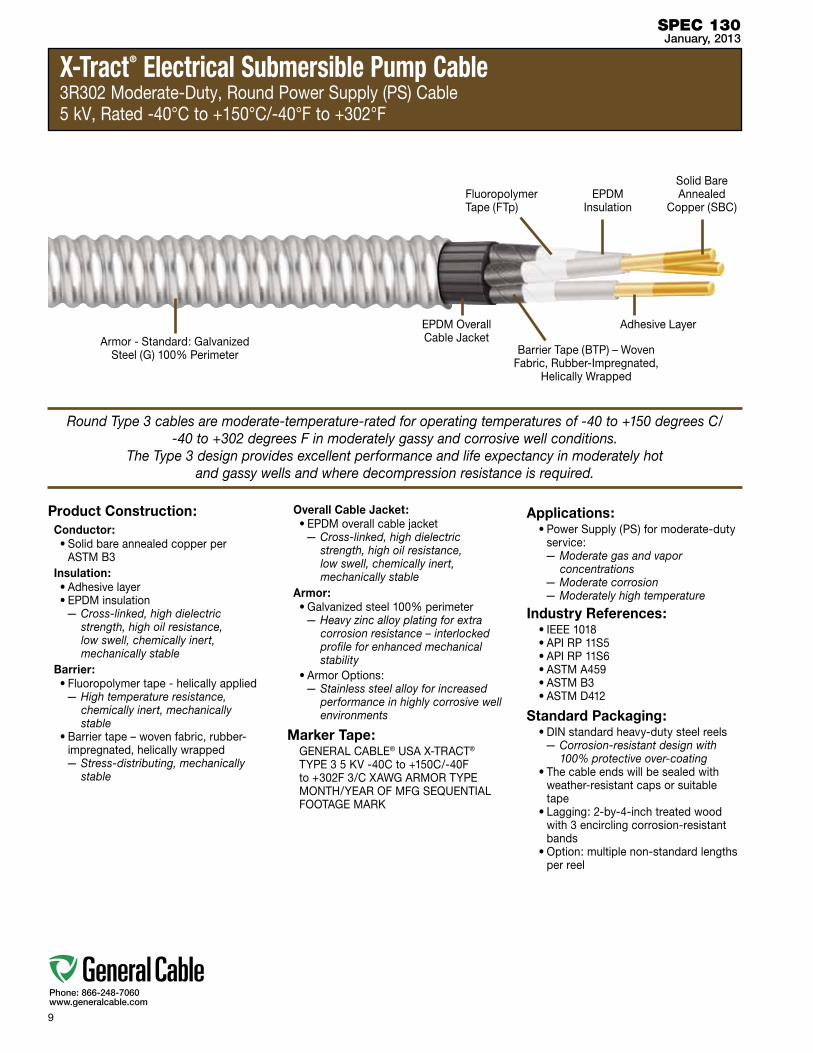
X-Tract® Electrical Submersible Pump Cable3R302 Moderate-Duty, Round Power Supply (PS) Cable 5 kV, Rated -40°C to +150°C/-40°F to +302°F
Product Construction:Conductor:•Solidbareannealedcopperper
ASTM B3Insulation:•Adhesivelayer•EPDMinsulation
— Cross-linked, high dielectric strength, high oil resistance, low swell, chemically inert, mechanically stable
Barrier:•Fluoropolymertape-helicallyapplied
— High temperature resistance, chemically inert, mechanically stable
•Barriertape–wovenfabric,rubber-impregnated, helically wrapped— Stress-distributing, mechanically
stable
Overall Cable Jacket:•EPDMoverallcablejacket
— Cross-linked, high dielectric strength, high oil resistance, low swell, chemically inert, mechanically stable
Armor:•Galvanizedsteel100%perimeter
— Heavy zinc alloy plating for extra corrosion resistance – interlocked profile for enhanced mechanical stability
•ArmorOptions:— Stainless steel alloy for increased
performance in highly corrosive well environments
Marker Tape:GENERAL CABLE® USA X-TRACT® TYPE 3 5 KV -40C to +150C/-40F to +302F 3/C XAWG ARMOR TYPE MONTH/YEAR OF MFG SEQUENTIAL FOOTAGE MARK
Applications:•PowerSupply(PS)formoderate-duty
service:— Moderate gas and vapor
concentrations— Moderate corrosion— Moderately high temperature
Industry References:•IEEE1018•APIRP11S5•APIRP11S6•ASTMA459•ASTMB3•ASTMD412
Standard Packaging:•DINstandardheavy-dutysteelreels
— Corrosion-resistant design with 100% protective over-coating
•Thecableendswillbesealedwithweather-resistant caps or suitable tape
•Lagging:2-by-4-inchtreatedwoodwith 3 encircling corrosion-resistant bands
•Option:multiplenon-standardlengthsper reel
SPEC 130January, 2013
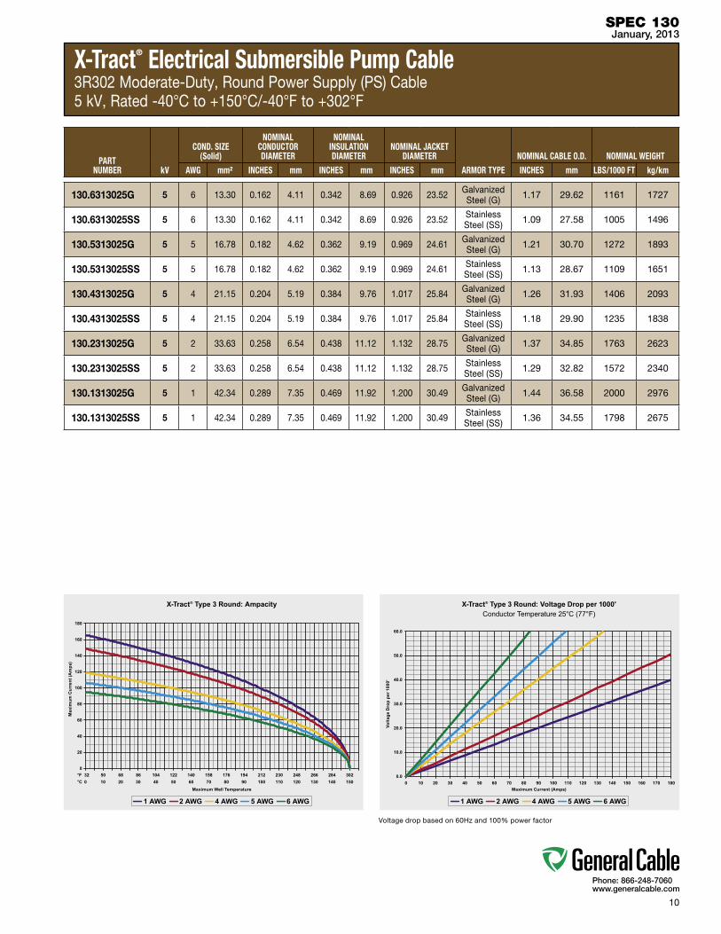
Round Type 3 cables are moderate-temperature-rated for operating temperatures of -40 to +150 degrees C/ -40 to +302 degrees F in moderately gassy and corrosive well conditions.
The Type 3 design provides excellent performance and life expectancy in moderately hot and gassy wells and where decompression resistance is required.
EPDM Overall Cable Jacket
Barrier Tape (BTP) – Woven Fabric, Rubber-Impregnated,
Helically Wrapped
EPDM Insulation
Adhesive Layer
Solid Bare Annealed
Copper (SBC)
Armor - Standard: Galvanized Steel(G)100%Perimeter
Fluoropolymer Tape (FTp)
10
Phone: 866-248-7060www.generalcable.com
X-Tract® Electrical Submersible Pump Cable3R302 Moderate-Duty, Round Power Supply (PS) Cable 5 kV, Rated -40°C to +150°C/-40°F to +302°F
SPEC 130January, 2013
PARTNUMBER kV
COND. SIZE (Solid)
NOMINAL CONDUCTOR DIAMETER
NOMINAL INSULATION DIAMETER
NOMINAL JACKET DIAMETER
ARMOR TYPE
NOMINAL CABLE O.D. NOMINAL WEIGHT
AWG mm² INCHES mm INCHES mm INCHES mm INCHES mm LBS/1000 fT kg/km
130.6313025G 5 6 13.30 0.162 4.11 0.342 8.69 0.926 23.52 Galvanized Steel (G) 1.17 29.62 1161 1727
130.6313025SS 5 6 13.30 0.162 4.11 0.342 8.69 0.926 23.52 Stainless Steel (SS) 1.09 27.58 1005 1496
130.5313025G 5 5 16.78 0.182 4.62 0.362 9.19 0.969 24.61 Galvanized Steel (G) 1.21 30.70 1272 1893
130.5313025SS 5 5 16.78 0.182 4.62 0.362 9.19 0.969 24.61 Stainless Steel (SS) 1.13 28.67 1109 1651
130.4313025G 5 4 21.15 0.204 5.19 0.384 9.76 1.017 25.84 Galvanized Steel (G) 1.26 31.93 1406 2093
130.4313025SS 5 4 21.15 0.204 5.19 0.384 9.76 1.017 25.84 Stainless Steel (SS) 1.18 29.90 1235 1838
130.2313025G 5 2 33.63 0.258 6.54 0.438 11.12 1.132 28.75 Galvanized Steel (G) 1.37 34.85 1763 2623
130.2313025SS 5 2 33.63 0.258 6.54 0.438 11.12 1.132 28.75 Stainless Steel (SS) 1.29 32.82 1572 2340
130.1313025G 5 1 42.34 0.289 7.35 0.469 11.92 1.200 30.49 Galvanized Steel (G) 1.44 36.58 2000 2976
130.1313025SS 5 1 42.34 0.289 7.35 0.469 11.92 1.200 30.49 Stainless Steel (SS) 1.36 34.55 1798 2675
Voltagedropbasedon60Hzand100%powerfactor
11
Phone: 866-248-7060www.generalcable.com
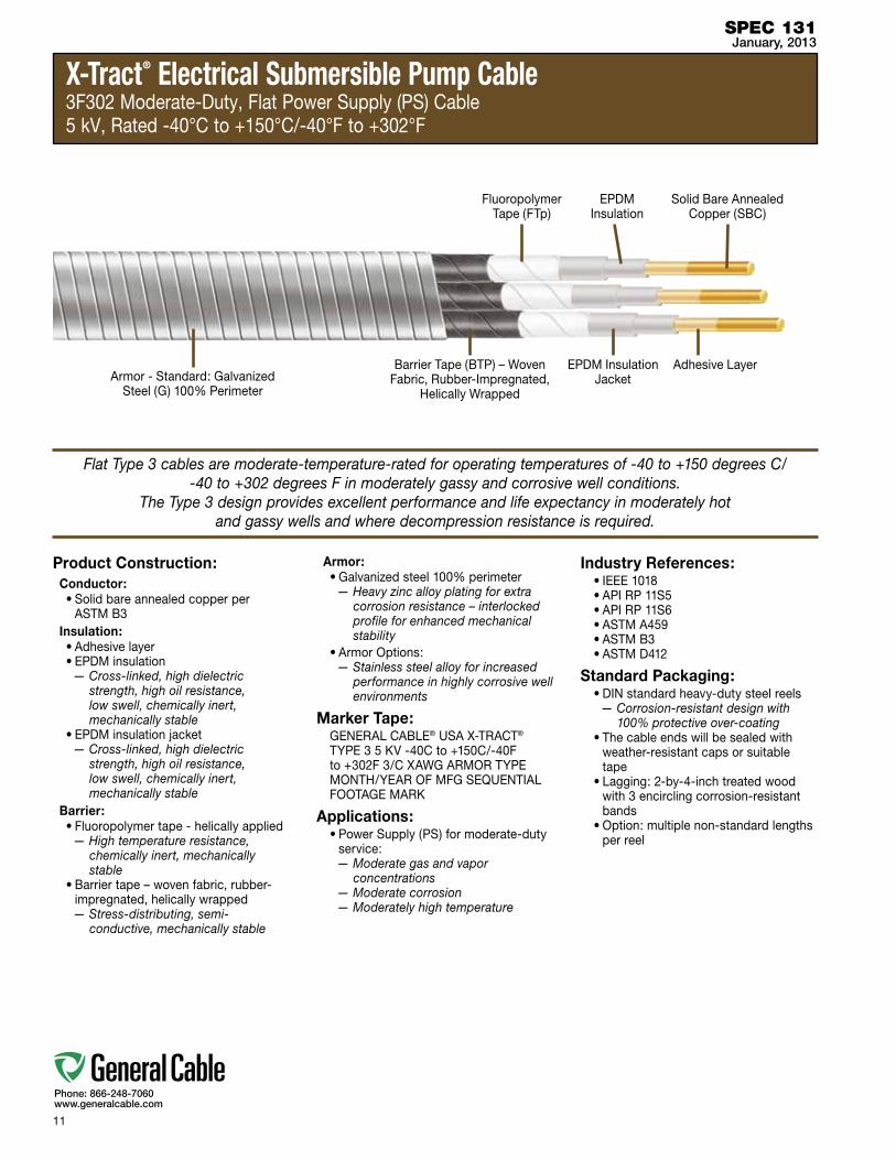
X-Tract® Electrical Submersible Pump Cable3F302 Moderate-Duty, Flat Power Supply (PS) Cable5 kV, Rated -40°C to +150°C/-40°F to +302°F
Product Construction:Conductor:•Solidbareannealedcopperper
ASTM B3Insulation:•Adhesivelayer•EPDMinsulation
— Cross-linked, high dielectric strength, high oil resistance, low swell, chemically inert, mechanically stable
•EPDMinsulationjacket— Cross-linked, high dielectric
strength, high oil resistance, low swell, chemically inert, mechanically stable
Barrier:•Fluoropolymertape-helicallyapplied
— High temperature resistance, chemically inert, mechanically stable
•Barriertape–wovenfabric,rubber-impregnated, helically wrapped— Stress-distributing, semi-
conductive, mechanically stable
Armor:•Galvanizedsteel100%perimeter
— Heavy zinc alloy plating for extra corrosion resistance – interlocked profile for enhanced mechanical stability
•ArmorOptions:— Stainless steel alloy for increased
performance in highly corrosive well environments
Marker Tape:GENERAL CABLE® USA X-TRACT® TYPE 3 5 KV -40C to +150C/-40F to +302F 3/C XAWG ARMOR TYPE MONTH/YEAR OF MFG SEQUENTIAL FOOTAGE MARK
Applications:•PowerSupply(PS)formoderate-duty
service:— Moderate gas and vapor
concentrations— Moderate corrosion— Moderately high temperature
Industry References:•IEEE1018•APIRP11S5•APIRP11S6•ASTMA459•ASTMB3•ASTMD412
Standard Packaging:•DINstandardheavy-dutysteelreels
— Corrosion-resistant design with 100% protective over-coating
•Thecableendswillbesealedwithweather-resistant caps or suitable tape
•Lagging:2-by-4-inchtreatedwoodwith 3 encircling corrosion-resistant bands
•Option:multiplenon-standardlengthsper reel
SPEC 131January, 2013
Flat Type 3 cables are moderate-temperature-rated for operating temperatures of -40 to +150 degrees C/ -40 to +302 degrees F in moderately gassy and corrosive well conditions.
The Type 3 design provides excellent performance and life expectancy in moderately hot and gassy wells and where decompression resistance is required.
Barrier Tape (BTP) – Woven Fabric, Rubber-Impregnated,
Helically Wrapped
EPDM Insulation
Adhesive LayerEPDM Insulation Jacket
Solid Bare Annealed Copper (SBC)
Armor - Standard: Galvanized Steel(G)100%Perimeter
Fluoropolymer Tape (FTp)

12
Phone: 866-248-7060www.generalcable.com
X-Tract® Electrical Submersible Pump Cable3F302 Moderate-Duty, Flat Power Supply (PS) Cable5 kV, Rated -40°C to +150°C/-40°F to +302°F
SPEC 131January, 2013
PARTNUMBER kV
COND. SIZE (Solid)
NOMINAL CONDUCTOR DIAMETER
NOMINAL INSULATION DIAMETER
ARMOR TYPE
fINISHED CABLE DIMENSIONS NOMINAL WEIGHT
AWG mm² INCHES mm INCHES mm INCHES mm LBS/1000 fT kg/km
131.6313025G 5 6 13.30 0.162 4.11 0.442 11.23 Galvanized Steel (G) 1.52 x 0.57 38.66 x 14.58 936 1392
131.6313025SS 5 6 13.30 0.162 4.11 0.442 11.23 Stainless Steel (SS) 1.5 x 0.55 38.02 x 13.94 829 1233
131.5313025G 5 5 16.78 0.182 4.62 0.462 11.73 Galvanized Steel (G) 1.58 x 0.59 40.18 x 15.09 1030 1533
131.5313025SS 5 5 16.78 0.182 4.62 0.462 11.73 Stainless Steel (SS) 1.56 x 0.57 39.54 x 14.45 920 1368
131.4313025G 5 4 21.15 0.204 5.19 0.484 12.30 Galvanized Steel (G) 1.65 x 0.62 41.88 x 15.65 1119 1665
131.4313025SS 5 4 21.15 0.204 5.19 0.484 12.30 Stainless Steel (SS) 1.62 x 0.59 41.25 x 15.02 1010 1503
131.2313025G 5 2 33.63 0.258 6.54 0.538 13.66 Galvanized Steel (G) 1.81 x 0.67 45.94 x 17.01 1427 2123
131.2313025SS 5 2 33.63 0.258 6.54 0.538 13.66 Stainless Steel (SS) 1.78 x 0.64 45.31 x 16.37 1308 1947
131.1313025G 5 1 42.34 0.289 7.35 0.569 14.46 Galvanized Steel (G) 1.9 x 0.7 48.36 x 17.81 1635 2433
131.1313025SS 5 1 42.34 0.289 7.35 0.569 14.46 Stainless Steel (SS) 1.88 x 0.68 47.72 x 17.18 1510 2247
Voltagedropbasedon60Hzand100%powerfactor
13
Phone: 866-248-7060www.generalcable.com
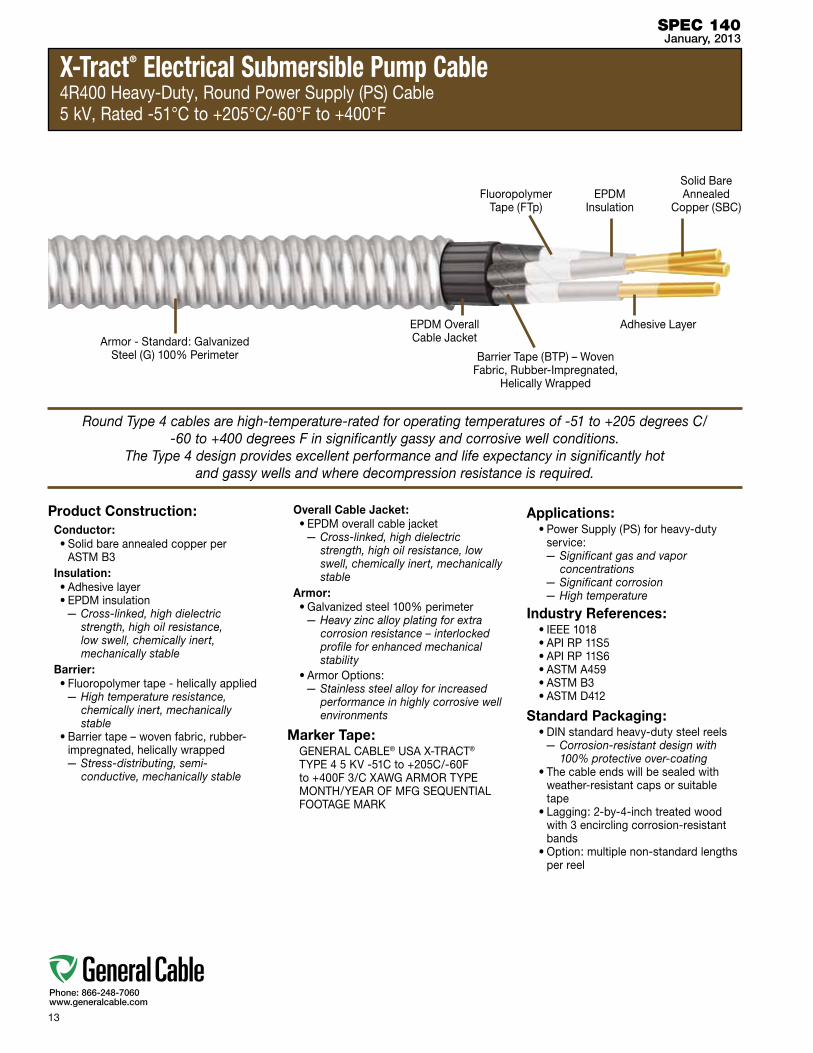
X-Tract® Electrical Submersible Pump Cable4R400 Heavy-Duty, Round Power Supply (PS) Cable5 kV, Rated -51°C to +205°C/-60°F to +400°F
Product Construction:Conductor:•Solidbareannealedcopperper
ASTM B3Insulation:•Adhesivelayer•EPDMinsulation
— Cross-linked, high dielectric strength, high oil resistance, low swell, chemically inert, mechanically stable
Barrier:•Fluoropolymertape-helicallyapplied
— High temperature resistance, chemically inert, mechanically stable
•Barriertape–wovenfabric,rubber-impregnated, helically wrapped— Stress-distributing, semi-
conductive, mechanically stable
Overall Cable Jacket:•EPDMoverallcablejacket
— Cross-linked, high dielectric strength, high oil resistance, low swell, chemically inert, mechanically stable
Armor:•Galvanizedsteel100%perimeter
— Heavy zinc alloy plating for extra corrosion resistance – interlocked profile for enhanced mechanical stability
•ArmorOptions:— Stainless steel alloy for increased
performance in highly corrosive well environments
Marker Tape:GENERAL CABLE® USA X-TRACT® TYPE 4 5 KV -51C to +205C/-60F to +400F 3/C XAWG ARMOR TYPE MONTH/YEAR OF MFG SEQUENTIAL FOOTAGE MARK
Applications:•PowerSupply(PS)forheavy-duty
service:— Significant gas and vapor
concentrations— Significant corrosion— High temperature
Industry References:•IEEE1018•APIRP11S5•APIRP11S6•ASTMA459•ASTMB3•ASTMD412
Standard Packaging:•DINstandardheavy-dutysteelreels
— Corrosion-resistant design with 100% protective over-coating
•Thecableendswillbesealedwithweather-resistant caps or suitable tape
•Lagging:2-by-4-inchtreatedwoodwith 3 encircling corrosion-resistant bands
•Option:multiplenon-standardlengthsper reel
SPEC 140January, 2013
Round Type 4 cables are high-temperature-rated for operating temperatures of -51 to +205 degrees C/ -60 to +400 degrees F in significantly gassy and corrosive well conditions.
The Type 4 design provides excellent performance and life expectancy in significantly hot and gassy wells and where decompression resistance is required.
EPDM Overall Cable Jacket
Barrier Tape (BTP) – Woven Fabric, Rubber-Impregnated,
Helically Wrapped
EPDM Insulation
Adhesive Layer
Solid Bare Annealed
Copper (SBC)
Armor - Standard: Galvanized Steel(G)100%Perimeter
Fluoropolymer Tape (FTp)

14
Phone: 866-248-7060www.generalcable.com
X-Tract® Electrical Submersible Pump Cable4R400 Heavy-Duty, Round Power Supply (PS) Cable5 kV, Rated -51°C to +205°C/-60°F to +400°F
SPEC 140January, 2013
PARTNUMBER kV
COND. SIZE (Solid)
NOMINAL CONDUCTOR DIAMETER
NOMINAL INSULATION DIAMETER
NOMINAL JACKET DIAMETER
ARMOR TYPE
NOMINAL CABLE O.D. NOMINAL WEIGHT
AWG mm² INCHES mm INCHES mm INCHES mm INCHES mm LBS/1000 fT kg/km
140.6314005G 5 6 13.30 0.162 4.11 0.342 8.69 0.926 23.52 Galvanized Steel (G) 1.17 29.62 1161 1727
140.6314005SS 5 6 13.30 0.162 4.11 0.342 8.69 0.926 23.52 Stainless Steel (SS) 1.09 27.58 1005 1496
140.5314005G 5 5 16.78 0.182 4.62 0.362 9.19 0.969 24.61 Galvanized Steel (G) 1.21 30.70 1272 1893
140.5314005SS 5 5 16.78 0.182 4.62 0.362 9.19 0.969 24.61 Stainless Steel (SS) 1.13 28.67 1109 1651
140.4314005G 5 4 21.15 0.204 5.19 0.384 9.76 1.017 25.84 Galvanized Steel (G) 1.26 31.93 1406 2093
140.4314005SS 5 4 21.15 0.204 5.19 0.384 9.76 1.017 25.84 Stainless Steel (SS) 1.18 29.90 1235 1838
140.2314005G 5 2 33.63 0.258 6.54 0.438 11.12 1.132 28.75 Galvanized Steel (G) 1.37 34.85 1763 2623
140.2314005SS 5 2 33.63 0.258 6.54 0.438 11.12 1.132 28.75 Stainless Steel (SS) 1.29 32.82 1572 2340
140.1314005G 5 1 42.34 0.289 7.35 0.469 11.92 1.200 30.49 Galvanized Steel (G) 1.44 36.58 2000 2976
140.1314005SS 5 1 42.34 0.289 7.35 0.469 11.92 1.200 30.49 Stainless Steel (SS) 1.36 34.55 1798 2675
Voltagedropbasedon60Hzand100%powerfactor

15
Phone: 866-248-7060www.generalcable.com
X-Tract® Electrical Submersible Pump Cable5F450 Severe-Duty, Flat Power Supply (PS) Cable 5 kV, Rated -51°C to +232°C/-60°F to +450°F
Product Construction:Conductor:•Solidbareannealedcopperper
ASTM B3Insulation:•Adhesivelayer•EPDMinsulation
— Cross-linked, high dielectric strength, high oil resistance, low swell, chemically inert, mechanically stable
Sheath:•Leadsheath–copper-bearingalloy
— Impervious extruded, high temperature, chemically resistant, mechanically stable
Barrier:•Barriertape–wovenfabric,rubber-
impregnated, helically wrapped— Stress-distributing, mechanically
stable
Armor:•Galvanizedsteel100%perimeter
— Heavy zinc alloy plating for extra corrosion resistance – interlocked profile for enhanced mechanical stability
•ArmorOptions:— Stainless steel alloy for increased
performance in highly corrosive well environments
Marker Tape:GENERAL CABLE® USA X-TRACT® TYPE 5 5 KV -51C to +232C/-60F to +450F 3/C XAWG ARMOR TYPE MONTH/YEAR OF MFG SEQUENTIAL FOOTAGE MARK
Applications:•PowerSupply(PS)forsevere-duty
service:— High gas and vapor concentrations— Severe corrosion— Very high temperature
Industry References:•IEEE1018•APIRP11S5•APIRP11S6•ASTMA459•ASTMB3•ASTMD412
Standard Packaging:•DINstandardheavy-dutysteelreels
— Corrosion-resistant design with 100% protective over-coating
•Thecableendswillbesealedwithweather-resistant caps or suitable tape
•Lagging:2-by-4-inchtreatedwoodwith 3 encircling corrosion-resistant bands
•Option:multiplenon-standardlengthsper reel
SPEC 151January, 2013
Flat Type 5 cables are high-temperature-rated for operating temperatures of -51 to +232 degrees C/ -60 to +450 degrees F and severe well conditions.
The Type 5 design provides excellent performance and life expectancy in hot, gassy wells and where decompression resistance is required.
Barrier Tape (BTP) – Woven Fabric, Rubber-Impregnated,
Helically Wrapped
EPDM Insulation
Adhesive Layer
Solid Bare Annealed
Copper (SBC)
Armor - Standard: Galvanized Steel(G)100%Perimeter
Lead Sheath – Copper-Bearing Alloy

16
Phone: 866-248-7060www.generalcable.com
X-Tract® Electrical Submersible Pump Cable5F450 Severe-Duty, Flat Power Supply (PS) Cable 5 kV, Rated -51°C to +232°C/-60°F to +450°F
SPEC 151January, 2013
PARTNUMBER kV
COND. SIZE (Solid)
NOMINAL CONDUCTOR DIAMETER
NOMINAL INSULATION*
DIAMETER
ARMOR TYPE
fINISHED CABLE DIMENSIONS NOMINAL WEIGHT
AWG mm² INCHES mm INCHES mm INCHES mm LBS/1000 fT kg/km
151.6314505G 5 6 13.30 0.162 4.11 0.312 7.92 Galvanized Steel (G) 1.32 x 0.51 33.48 x 12.85 1303 1938
151.6314505SS 5 6 13.30 0.162 4.11 0.312 7.92 Stainless Steel (SS) 1.29 x 0.48 32.84 x 12.22 1209 1800
151.5314505G 5 5 16.78 0.182 4.62 0.332 8.43 Galvanized Steel (G) 1.38 x 0.53 34.99 x 13.36 1400 2083
151.5314505SS 5 5 16.78 0.182 4.62 0.332 8.43 Stainless Steel (SS) 1.35 x 0.5 34.36 x 12.72 1308 1946
151.4314505G 5 4 21.15 0.204 5.19 0.354 9.00 Galvanized Steel (G) 1.44 x 0.55 36.7 x 13.93 1543 2295
151.4314505SS 5 4 21.15 0.204 5.19 0.354 9.00 Stainless Steel (SS) 1.42 x 0.52 36.07 x 13.29 1446 2152
151.2314505G 5 2 33.63 0.258 6.54 0.408 10.35 Galvanized Steel (G) 1.6 x 0.6 40.76 x 15.28 1918 2855
151.2314505SS 5 2 33.63 0.258 6.54 0.408 10.35 Stainless Steel (SS) 1.58 x 0.58 40.13 x 14.65 1812 2697
151.1314505G 5 1 42.34 0.289 7.35 0.439 11.16 Galvanized Steel (G) 1.7 x 0.63 43.18 x 16.09 2166 3224
151.1314505SS 5 1 42.34 0.289 7.35 0.439 11.16 Stainless Steel (SS) 1.67 x 0.61 42.54 x 15.45 2054 3057
*Pre-lead sheath
Voltagedropbasedon60Hzand100%powerfactor
17
Phone: 866-248-7060www.generalcable.com
Table of ContentsTechnical Information
TechnicalJanuary, 2013
Technical Information SPECIFICATION DESCRIPTION REVISION DATE PAGE
Technical Table of Contents Jan. 2013 17
Technical Recommended Installation Practice Jan. 2013 18-27
Technical Testing Jan. 2013 28-29
H005 Voltage Drop and Ampacity Calculation Jan. 2013 30-33
A018 ESP Cable Cross-Reference Jan. 2013 34
A150 Metric Conversion Factors Sept. 2010 35
A185 AWG (American Wire Gauge) to mm2 (Millimeters Squared) Conversion Sept. 2010 36
Index Part Number Index Jan. 2013 37

18
Phone: 866-248-7060www.generalcable.com
Recommended Installation Practice: X-Tract® ESP Cables
TechnicalJanuary, 2013
This Recommended Installation Practice is written for guidance when handling Electrical Submersible Pump (ESP) cables at a well site. Recommended practice for transportation and storage references are made by General Cable; installation recommendations are made with reference to API RP 11S3 Recommended Practice for Electrical Submersible Pump Installations, IEEE 1018 Recommended Practice for Specifying Electric Submersible Pump Cable Ethylene-Propylene Rubber Insulation and IEEE 1019 Recommended Practice for Specifying Electric Submersible Pump Cable Polypropylene Insulation.
General Cable manufactures its X-Tract® ESP cables for downhole – oil and water well - applications with reference to IEEE 1018, IEEE 1019 and API RP 11S6 Recommended Practice for Testing of Electrical Submersible Pump Cable Systems. They are produced under strict supervision and enforced quality systems approved to ISO 9001- 2008 (UL DQS).
This Recommended Installation Practice is based upon:
API Recommended Practice API RP 11S3:Applicable clauses:
3.0 Transportation, Handling, and Storage of Equipment (Reel Diagram)
5.4 Cable Spoolers or Reels
5.5 Downhole Cable Protection
5.6 Cable Sheave
6.0 Running Equipment into the Well
6.2.1/6.2.2 Use of a Gauging Tool to Eliminate Burrs, etc.
6.4.4 Shipping Caps
6.4.5 Insulation Resistance Test during Lifting
6.5 Cable Splicing
6.6 Cable Banding
6.8 Running Practices
7.1.5 Phase-to-Ground IR Test
8.1.1 Historical data (Pulling Equipment out of Wells)
9.1.1 Downhole Pump Cables (Field Evaluation of Used Equipment)
9.1.6.3 Minimum HV IR Requirement
10.1 Downhole Pump Cables (Assessment of Used Equipment)

19
Phone: 866-248-7060www.generalcable.com
Recommended Installation Practice: X-Tract® ESP Cables
TechnicalJanuary, 2013
API Recommended Practice API RP 11S6:Applicable clauses:
9.0 In Situ Testing
10.0 Diagnostic (Fault) Testing
11.0 Insulation Resistance (Megohmmeter) Tests
14.3 Time Domain Reflectometer Tests (Fault Location)
IEEE 1018:Applicable clauses:
10.2.1 Installation (Reference API RP 11S3, Section 5.6)
10.2.2 Pull Rates (Minimizing Soluble Gas-Induced Damage)
10.2.3 Chemical Treatments (Particular Reference to Nitrile Jackets)
10.2.4 Balancing Flat Cable Phase Currents
IEEE 1019:Applicable clauses:
9.2.1 Installation (reference API RP 11S3, Section 5.6)
9.2.2 Pull Rates (Minimizing Soluble Gas-Induced Damage)
9.2.3 Chemical Treatments (Particular Reference to Nitrile Jackets)
9.2.4 Balancing Flat Cable Phase Currents
General Cable Specification:
Recommended Installation Practice: X-Tract® ESP Cable
20
Phone: 866-248-7060www.generalcable.com
1.Transportation, Handling and Storage of Downhole ESP Cables
Cable packaging is in accordance with contractual requirement when shipped from the factory. Prior to shipment,allcablesaresubjectedto100%in-processtestingandroutinetests to ensure the finished cable is within specification. These tests are referenced in API RP 11S6, IEEE 1018 and IEEE 1019 as well as all relevant pages from the X-Tract® catalog.
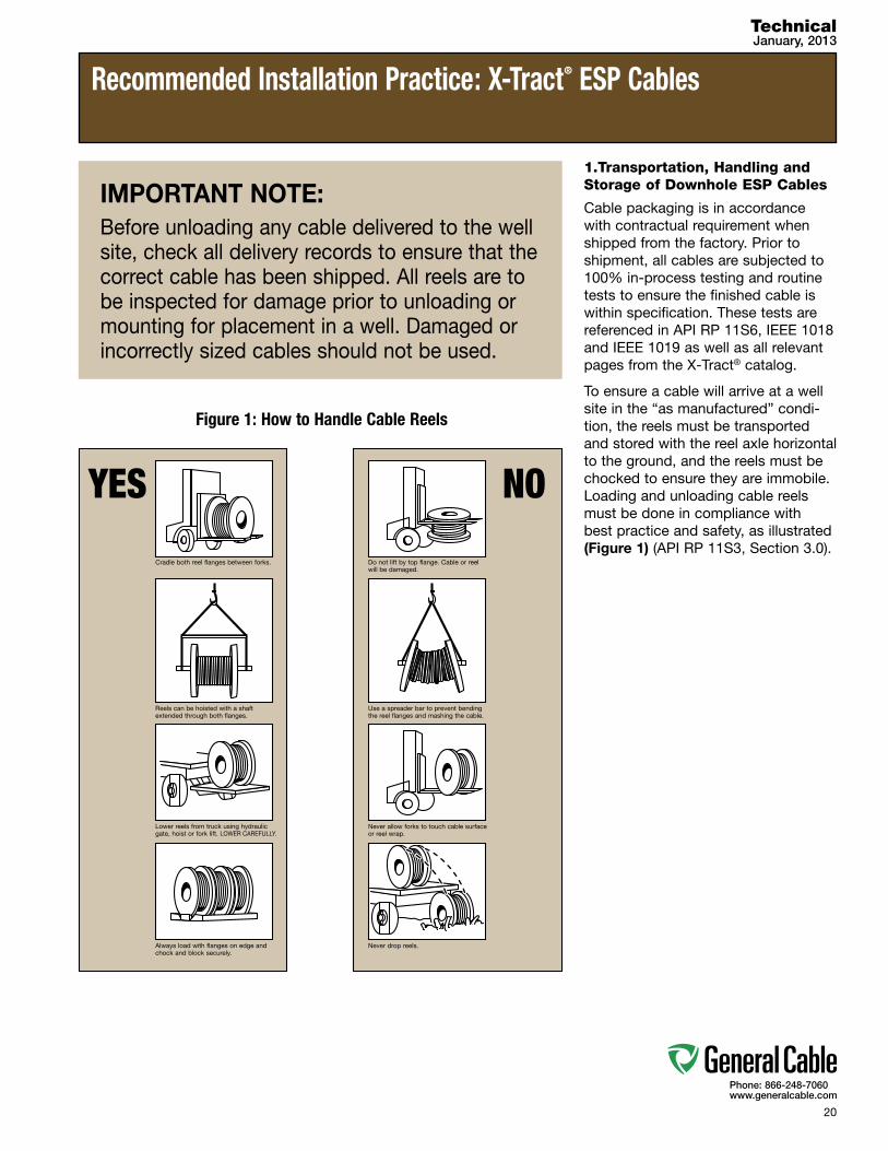
To ensure a cable will arrive at a well site in the “as manufactured” condi-tion, the reels must be transported and stored with the reel axle horizontal to the ground, and the reels must be chocked to ensure they are immobile. Loading and unloading cable reels must be done in compliance with best practice and safety, as illustrated (Figure 1) (API RP 11S3, Section 3.0).
IMPORTANT NOTE:Before unloading any cable delivered to the well site, check all delivery records to ensure that the correct cable has been shipped. All reels are to be inspected for damage prior to unloading or mounting for placement in a well. Damaged or incorrectly sized cables should not be used.
figure 1: How to Handle Cable Reels
Recommended Installation Practice: X-Tract® ESP Cables
TechnicalJanuary, 2013
YES NO
Cradle both reel flanges between forks.
Reels can be hoisted with a shaft extended through both flanges.
Lower reels from truck using hydraulic gate, hoist or fork lift. LOWER CAREFULLY.
Always load with flanges on edge and chock and block securely.
Do not lift by top flange. Cable or reel will be damaged.
Use a spreader bar to prevent bending the reel flanges and mashing the cable.
Never allow forks to touch cable surface or reel wrap.
Never drop reels.
21
Phone: 866-248-7060www.generalcable.com
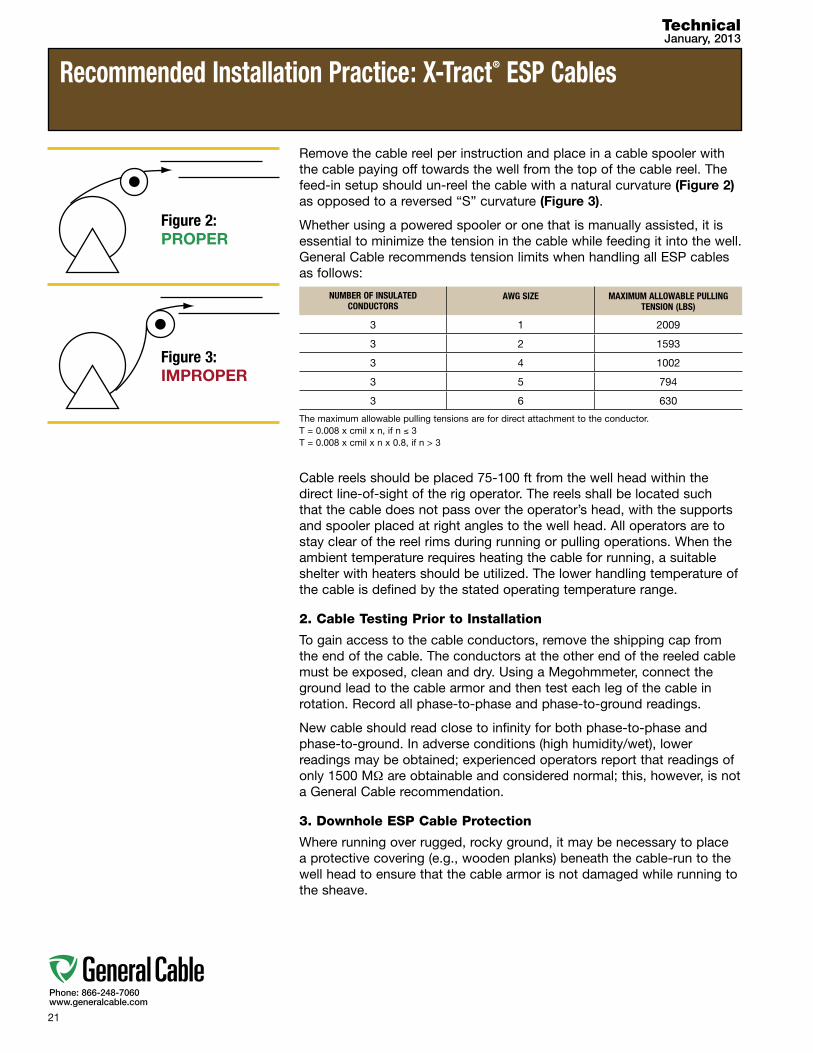
Remove the cable reel per instruction and place in a cable spooler with the cable paying off towards the well from the top of the cable reel. The feed-in setup should un-reel the cable with a natural curvature (Figure 2) as opposed to a reversed “S” curvature (Figure 3).
Whether using a powered spooler or one that is manually assisted, it is essential to minimize the tension in the cable while feeding it into the well. General Cable recommends tension limits when handling all ESP cables as follows:
Cable reels should be placed 75-100 ft from the well head within the direct line-of-sight of the rig operator. The reels shall be located such that the cable does not pass over the operator’s head, with the supports and spooler placed at right angles to the well head. All operators are to stay clear of the reel rims during running or pulling operations. When the ambient temperature requires heating the cable for running, a suitable shelter with heaters should be utilized. The lower handling temperature of the cable is defined by the stated operating temperature range.
2. Cable Testing Prior to Installation
To gain access to the cable conductors, remove the shipping cap from the end of the cable. The conductors at the other end of the reeled cable must be exposed, clean and dry. Using a Megohmmeter, connect the ground lead to the cable armor and then test each leg of the cable in rotation. Record all phase-to-phase and phase-to-ground readings.
New cable should read close to infinity for both phase-to-phase and phase-to-ground. In adverse conditions (high humidity/wet), lower readings may be obtained; experienced operators report that readings of only 1500 MΩ are obtainable and considered normal; this, however, is not a General Cable recommendation.
3. Downhole ESP Cable Protection
Where running over rugged, rocky ground, it may be necessary to place a protective covering (e.g., wooden planks) beneath the cable-run to the well head to ensure that the cable armor is not damaged while running to the sheave.
Recommended Installation Practice: X-Tract® ESP Cables
TechnicalJanuary, 2013
figure 2: PROPER
figure 3: IMPROPER
NUMBER Of INSULATED CONDUCTORS
AWG SIZE MAXIMUM ALLOWABLE PULLING TENSION (LBS)
3 1 2009
3 2 1593
3 4 1002
3 5 794
3 6 630
The maximum allowable pulling tensions are for direct attachment to the conductor.T = 0.008 x cmil x n, if n ≤ 3T = 0.008 x cmil x n x 0.8, if n > 3

22
Phone: 866-248-7060www.generalcable.com
4. Cable Sheave
A cable sheave is to be used when running or pulling downhole ESP cable. The sheaves should have a minimum 54 inch (1.4 m) diameter and beofsuchconstructiontopreventcablesfromjumpingoffthesheaveduring operation. Single or “gooseneck” conveyor-type sheaves may be used if the minimum diameter requirement is satisfied.
For pulling around bends, use conveyor sheave assemblies of the appropriate radius series (Figure 4).
The pulleys must be positioned to ensure that the effective curvature is smooth and changes directions or elevation evenly at each pulley. Never allow a polygon curvature to occur (Figure 5). The fit of a pulley around the cable is also important when pulling heavy weights (i.e., pulleys at the top of a vertical drop).
During installation, the sheave should be supported above ground when preparing to feed the cable through it (Figure 6). After the cable has been fed through and has been securely banded to the tubing, the sheave shall be raised to the “running position”, approximately 25-45 ft (8-14 m) above the slips (the electrical connections made through a rotating assembly). The sheave should then be secured such that the cable is as close as possible inline with the movement of the travelling blocks which support the drill column and “travel” up and down as it hoists the pipe in and out of the hole. The cable should not be used to reposition the sheave. Note: When flat pump cable is being run, a flat rimmed sheave is to be used.
Recommended Installation Practice: X-Tract® ESP Cables
TechnicalJanuary, 2013
figure 4: SHEAVE ASSEMBLYNote: Effective diameter not to be < 54 inches
figure 5: NEVER ALLOW
figure 6
23
Phone: 866-248-7060www.generalcable.com
5. Casing Check
It is recommended that a full-gauge tool or a full-bore casing scraper be run through the casing prior to inserting the downhole ESP cable to remove burrs and ensure adequate clearance for the assembly.
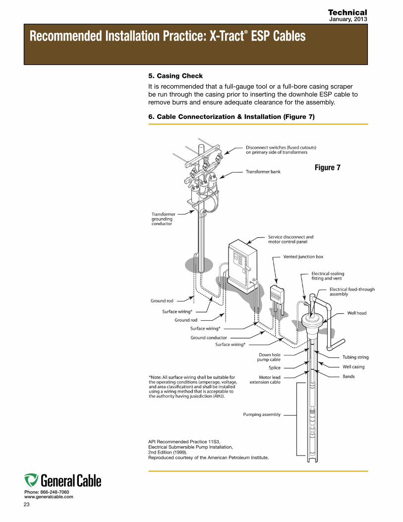
6. Cable Connectorization & Installation (Figure 7)
API Recommended Practice 11S3, Electrical Submersible Pump Installation, 2nd Edition (1999). Reproduced courtesy of the American Petroleum Institute.
Recommended Installation Practice: X-Tract® ESP Cables
TechnicalJanuary, 2013
figure 7
24
Phone: 866-248-7060www.generalcable.com
Recommended Installation Practice: X-Tract® ESP Cables
TechnicalJanuary, 2013
figure 8
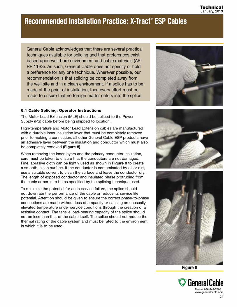
6.1 Cable Splicing: Operator Instructions
The Motor Lead Extension (MLE) should be spliced to the Power Supply (PS) cable before being shipped to location.
High-temperature and Motor Lead Extension cables are manufactured with a durable inner insulation layer that must be completely removed prior to making a connection; all other General Cable ESP products have an adhesive layer between the insulation and conductor which must also be completely removed (Figure 8).
When removing the inner layers and the primary conductor insulation, care must be taken to ensure that the conductors are not damaged. Fine, abrasive cloth can be lightly used as shown in Figure 8 to create a smooth, clean surface. If the conductor is contaminated by oil or dirt, use a suitable solvent to clean the surface and leave the conductor dry. The length of exposed conductor and insulated phase protruding from the cable armor is to be as specified by the splicing technique used.
To minimize the potential for an in-service failure, the splice should not downrate the performance of the cable or reduce its service life potential. Attention should be given to ensure the correct phase-to-phase connections are made without loss of ampacity or causing an unusually elevated temperature under service conditions through the creation of a resistive contact. The tensile load-bearing capacity of the splice should not be less than that of the cable itself. The splice should not reduce the thermal rating of the cable system and must be rated to the environment in which it is to be used.
General Cable acknowledges that there are several practical techniques available for splicing and that preferences exist based upon well-bore environment and cable materials (API RP 11S3). As such, General Cable does not specify or hold a preference for any one technique. Wherever possible, our recommendation is that splicing be completed away from the well site and in a clean environment. If a splice has to be made at the point of installation, then every effort must be made to ensure that no foreign matter enters into the splice.

25
Phone: 866-248-7060www.generalcable.com
6.2 Cable Connections
Different types of connections are made during the set-up process, again offering many options that reflect both the severity of the environment and the personal preference of the operator/owner.
Types of Connections:
•Potheads (Figure 9)
•WellHeadPenetrators
•DownholeConnectors
•PackerFeed-Through
•Breakoutformultiplefeedtomotorsintandem
Inallinstances,whereacableistobejoinedorconnected,followingthe specific manufacturer’s instructions ensures that the cable is not damaged and that the electrical connection is clean and well-made.
6.3 Cable Banding
Proper banding reduces the amount of strain a cable takes in its vertical installation — reduced vibration increases the life of the cable. The term “banding” is used generically and includes bands and cable clamps/protectors.
To achieve correct and consistent band tension, pneumatic tensioning is the preferred method for all banding of X-Tract® ESP cable. Tightening should be sufficient to ensure that the cable does not slip once attached to the tubing and that the cable itself is not damaged. A slight distortion of the cable armor is acceptable and indeed a good indication of appropriate tightness, but the armor should not be crushed. If a band is loose, it is recommended that it be cut off and replaced.
To attain a proper cable band (Figure 10):
•Bandingtoolsshouldbeingoodconditionandadjustedcorrectly.Personnel using these tools should be trained and supervised to ensure proper banding (API RP 11S3, Section 6.6 Cable Banding).
•Bandsmustbeplacedsothatthebuckleislocatedinthevoidbetween the cable and the tubing, out of the way of the banding tools and thus unable to be pushed into the cable and causing damage to it.
•Cablebandsshouldnotbeinstalledoveracablesplicebutratherabove and below it so as not to place any load on the splice.
•WhenplacingbandsonaMotorLeadExtension,makesurethecablefits up above the pump discharge head and not across a tubing collar.
Per API RP 11S3, no less than two bands are to be applied to secure thedownholeESPcablepertubingjoint,withonebeingattached midwayoverthejointitselfandtheother2-3ft(60-90cm)abovethecollar.However,morebandsshouldbeusedonthefirsttwojoints(approx. 60 ft/18.29 m), as well as when running the tubing through a dogleg or other tight spots. This practice provides extra cable support in the area of “tubing cut-off” that might occur during a fishing operation.
Recommended Installation Practice: X-Tract® ESP Cables
TechnicalJanuary, 2013
figure 9:Installation of the pothead prior to cable
delivery to a well site is preferable
figure 10:Shows proper banding around a coupler
Clamp/Protector
Band
Cable
Coupling
Casing, Inner Wall
Tube

26
Phone: 866-248-7060www.generalcable.com
7. Motor Lead Extension (MLE) Cable
ESP cables that have a Motor Lead Extension attached at a location away from the well site must be repackaged with the power cable reel prior to shipping to safeguard against in-transit damage.
MLE cable that is shipped separately (unattached to a ESP cable) should be boxed, crated, reeled or secured to a pallet/skid. To protect the MLE from weather damage and/or contamination, each end of the lead should be sealed.
8. Running Practices (API RP 11S3, Section 6.8)
Themajorityofcabledamageoccursduringhandlingand/orinstallationin a well casing. Running and pulling well tubing must be done slowly and smoothly. While running a new assembly into a well, rapid acceleration and deceleration may cause cable damage. It is not good practice to allow the cable to drag on the ground; cable slack should be maintained between the reel and the sheave. The cable should reel on or off the top of the reel.
Electrical continuity and insulation resistance should be measured periodically at:
(a) a minimum of once every 2000 ft (610 m)
(b) at pump depth setting
(c) when terminations or splices are made
Run speed is to be defined by the operator taking account of experience and preference. Some operators set a limit of 1000 ft/hr (305 m/hr); this, however, is outside the scope of this Recommended Practice.
Note: IEEE 1018 and 1019 give run speeds in the range of 1000-4000 ft/hr (305-1219 m/hr) as being normal.
Recommended Installation Practice: X-Tract® ESP Cables
TechnicalJanuary, 2013
figure 11:Minimum requirement for ESP cable with an MLE spliced at a remote location prior to delivery at the well site (API RP 11S3, Section 3.0)
API Recommended Practice 11S3, Electrical Submersible Pump Installation, 2nd Edition (1999). Reproduced courtesy of the American Petroleum Institute.

27
Phone: 866-248-7060www.generalcable.com
8.1 Pulling and Assessment of Used Cable
Pulling requires as much attention to detail and caution as running new equipment. Once all the preparations have been made, including opening the bleeder valve to remove the fluid, begin lifting the pump string out of the well.
A record of the number of bands that are missing should be kept, and the decision should be made whether to retrieve or push them to the bottom of the well. Remove the bands progressively by cutting and not by levering them away from the tube/cable, as that will damage the cable. If there is evidence of corrosion on the bands, it may be necessary to change them when re-establishing the well with bands of higher corrosion resistance.
Observe the condition of the cable as it emerges from the well. Look for evidence of overheating, melted lead, scorch marks on the armor and corroded or separated armor. Check for swollen insulation, exposed conductors and excessive corrosion of cable splices, as well as the number of splices. If there is a reported motor failure, ask the owner/operator whether to leave a portion of the MLE attached (1-2 ft [30-60 cm] above the pothead) or if it should be removed completely.
8.2 Guidelines for Established Re-Use of Cable
All observed issues with the cable should be marked on the cable while it is being recovered; this will save time in locating the defects for repair or deciding whether to scrap the cable length as a whole. The retrieved cable should be re-spooled on a reel of sufficient capacity for the length, size and type of cable being pulled. Do not run the cable across the ground and reel with the cable running onto the top of the reel. Lightly oil the cable and store it in a sheltered location if possible.
All cable lengths are to be tested according to API RP 11S6 prior to and after any repairs being made before they can be considered for an additional period in service. Failure of a test after repair should render the cable unfit for use. It is good practice to allow a cable to rest for several days prior to testing; this will reduce the content of soluble or entrapped gases.
Note: Motor Lead Extensions should not be re-used.
Recommended Installation Practice: X-Tract® ESP Cables
TechnicalJanuary, 2013
28
Phone: 866-248-7060www.generalcable.com
Testing
TechnicalJanuary, 2013
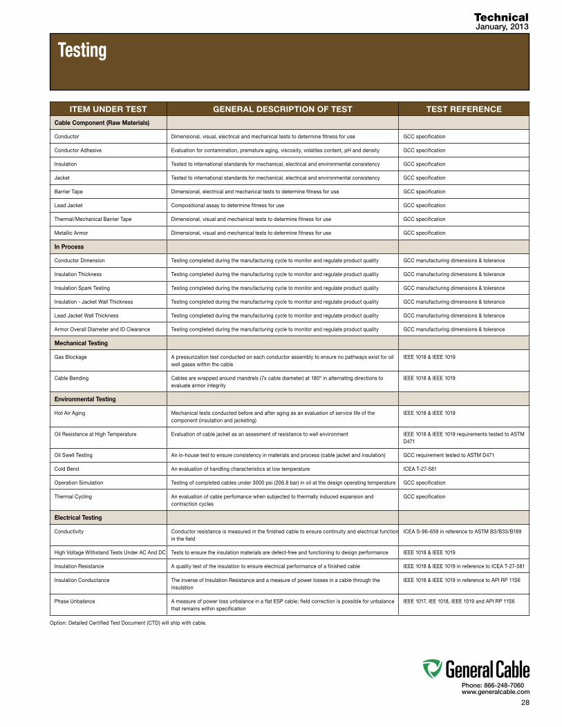
ITEM UNDER TEST GENERAL DESCRIPTION OF TEST TEST REFERENCE
Cable Component (Raw Materials)
Conductor Dimensional, visual, electrical and mechanical tests to determine fitness for use GCC specification
Conductor Adhesive Evaluation for contamination, premature aging, viscosity, volatiles content, pH and density GCC specification
Insulation Tested to international standards for mechanical, electrical and environmental consistency GCC specification
Jacket Tested to international standards for mechanical, electrical and environmental consistency GCC specification
Barrier Tape Dimensional, electrical and mechanical tests to determine fitness for use GCC specification
Lead Jacket Compositional assay to determine fitness for use GCC specification
Thermal/Mechanical Barrier Tape Dimensional, visual and mechanical tests to determine fitness for use GCC specification
Metallic Armor Dimensional, visual and mechanical tests to determine fitness for use GCC specification
In Process
Conductor Dimension Testing completed during the manufacturing cycle to monitor and regulate product quality GCC manufacturing dimensions & tolerance
Insulation Thickness Testing completed during the manufacturing cycle to monitor and regulate product quality GCC manufacturing dimensions & tolerance
Insulation Spark Testing Testing completed during the manufacturing cycle to monitor and regulate product quality GCC manufacturing dimensions & tolerance
Insulation - Jacket Wall Thickness Testing completed during the manufacturing cycle to monitor and regulate product quality GCC manufacturing dimensions & tolerance
Lead Jacket Wall Thickness Testing completed during the manufacturing cycle to monitor and regulate product quality GCC manufacturing dimensions & tolerance
Armor Overall Diameter and ID Clearance Testing completed during the manufacturing cycle to monitor and regulate product quality GCC manufacturing dimensions & tolerance
Mechanical Testing
Gas Blockage A pressurization test conducted on each conductor assembly to ensure no pathways exist for oil well gases within the cable
IEEE 1018 & IEEE 1019
Cable Bending Cables are wrapped around mandrels (7x cable diameter) at 180º in alternating directions to evaluate armor integrity
IEEE 1018 & IEEE 1019
Environmental Testing
Hot Air Aging Mechanical tests conducted before and after aging as an evaluation of service life of the component(insulationandjacketing)
IEEE 1018 & IEEE 1019
Oil Resistance at High Temperature Evaluationofcablejacketasanassesmentofresistancetowellenvironment IEEE 1018 & IEEE 1019 requirements tested to ASTM D471
Oil Swell Testing Anin-housetesttoensureconsistencyinmaterialsandprocess(cablejacketandinsulation) GCC requirement tested to ASTM D471
Cold Bend An evaluation of handling characteristics at low temperature ICEA T-27-581
Operation Simulation Testing of completed cables under 3000 psi (206.8 bar) in oil at the design operating temperature GCC specification
Thermal Cycling Anevaluationofcableperfomancewhensubjectedtothermallyinducedexpansionandcontraction cycles
GCC specification
Electrical Testing
Conductivity Conductor resistance is measured in the finished cable to ensure continuity and electrical function in the field
ICEA S-96-659 in reference to ASTM B3/B33/B189
High Voltage Withstand Tests Under AC And DC Tests to ensure the insulation materials are defect-free and functioning to design performance IEEE 1018 & IEEE 1019
Insulation Resistance A quality test of the insulation to ensure electrical performance of a finished cable IEEE 1018 & IEEE 1019 in reference to ICEA T-27-581
Insulation Conductance The inverse of Insulation Resistance and a measure of power losses in a cable through the insulation
IEEE 1018 & IEEE 1019 in reference to API RP 11S6
Phase Unbalance A measure of power loss unbalance in a flat ESP cable; field correction is possible for unbalance that remains within specification
IEEE 1017, IEE 1018, IEEE 1019 and API RP 11S6
Option: Detailed Certified Test Document (CTD) will ship with cable.
29
Phone: 866-248-7060www.generalcable.com
Testing
TechnicalJanuary, 2013
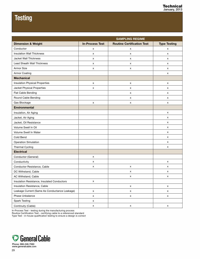
SAMPLING REGIME
Dimension & Weight In-Process Test Routine Certification Test Type Testing
Conductor x x x
Insulation Wall Thickness x x x
Jacket Wall Thickness x x x
Lead Sheath Wall Thickness x x x
Armor Size x x x
Armor Coating x
Mechanical
Insulation Physical Properties x x x
Jacket Physical Properties x x x
Flat Cable Bending x x
Round Cable Bending x x
Gas Blockage x x x
Environmental
Insulation, Air Aging x
Jacket, Air Aging x
Jacket, Oil Resistance x
Volume Swell In Oil x
Volume Swell In Water x
Cold Bend x
Operation Simulation x
Thermal Cycling x
Electrical
Conductor (General) x
Conductivity x x
Conductor Resistance, Cable x x x
DC Withstand, Cable x x
AC Withstand, Cable x x
Insulation Resistance, Insulated Conductors x
Insulation Resistance, Cable x x
Leakage Current (Same As Conductance Leakage) x x x
Phase Unbalance x x x
Spark Testing x
Continuity (Cable) x x x
In-Process Test - testing during the manufacturing process Routine Certification Test - certifying cable to a referenced standard Type Test - in-house qualification testing to ensure a design is correct
30
Phone: 866-248-7060www.generalcable.com
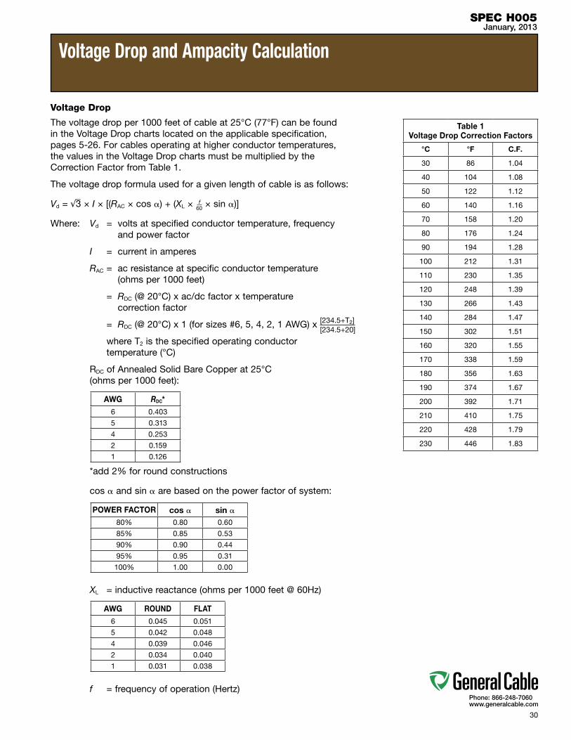
Voltage Drop
The voltage drop per 1000 feet of cable at 25°C (77°F) can be found in the Voltage Drop charts located on the applicable specification, pages 5-26. For cables operating at higher conductor temperatures, the values in the Voltage Drop charts must be multiplied by the Correction Factor from Table 1.
The voltage drop formula used for a given length of cable is as follows:
Vd = √3 × I × [(RAC × cos ) + (XL × f60 × sin )]
Where: Vd = volts at specified conductor temperature, frequency and power factor
I = current in amperes
RAC = ac resistance at specific conductor temperature (ohms per 1000 feet)
= RDC (@ 20°C) x ac/dc factor x temperature correction factor
= RDC (@ 20°C) x 1 (for sizes #6, 5, 4, 2, 1 AWG) x [234.5+T2]
where T2 is the specified operating conductor temperature (°C)
RDC of Annealed Solid Bare Copper at 25°C (ohms per 1000 feet):
*add2%forroundconstructions
cos and sin are based on the power factor of system:
XL = inductive reactance (ohms per 1000 feet @ 60Hz)
f = frequency of operation (Hertz)
Voltage Drop and Ampacity Calculation
SPEC H005January, 2013
[234.5+20]
Table 1 Voltage Drop Correction Factors
°C °F C.F.
30 86 1.04
40 104 1.08
50 122 1.12
60 140 1.16
70 158 1.20
80 176 1.24
90 194 1.28
100 212 1.31
110 230 1.35
120 248 1.39
130 266 1.43
140 284 1.47
150 302 1.51
160 320 1.55
170 338 1.59
180 356 1.63
190 374 1.67
200 392 1.71
210 410 1.75
220 428 1.79
230 446 1.83
AWG RDC*6 0.403
5 0.313
4 0.253
2 0.159
1 0.126
AWG ROUND FLAT6 0.045 0.051
5 0.042 0.048
4 0.039 0.046
2 0.034 0.040
1 0.031 0.038
POWER FACTOR cos sin 80% 0.80 0.60
85% 0.85 0.53
90% 0.90 0.44
95% 0.95 0.31
100% 1.00 0.00
31
Phone: 866-248-7060www.generalcable.com
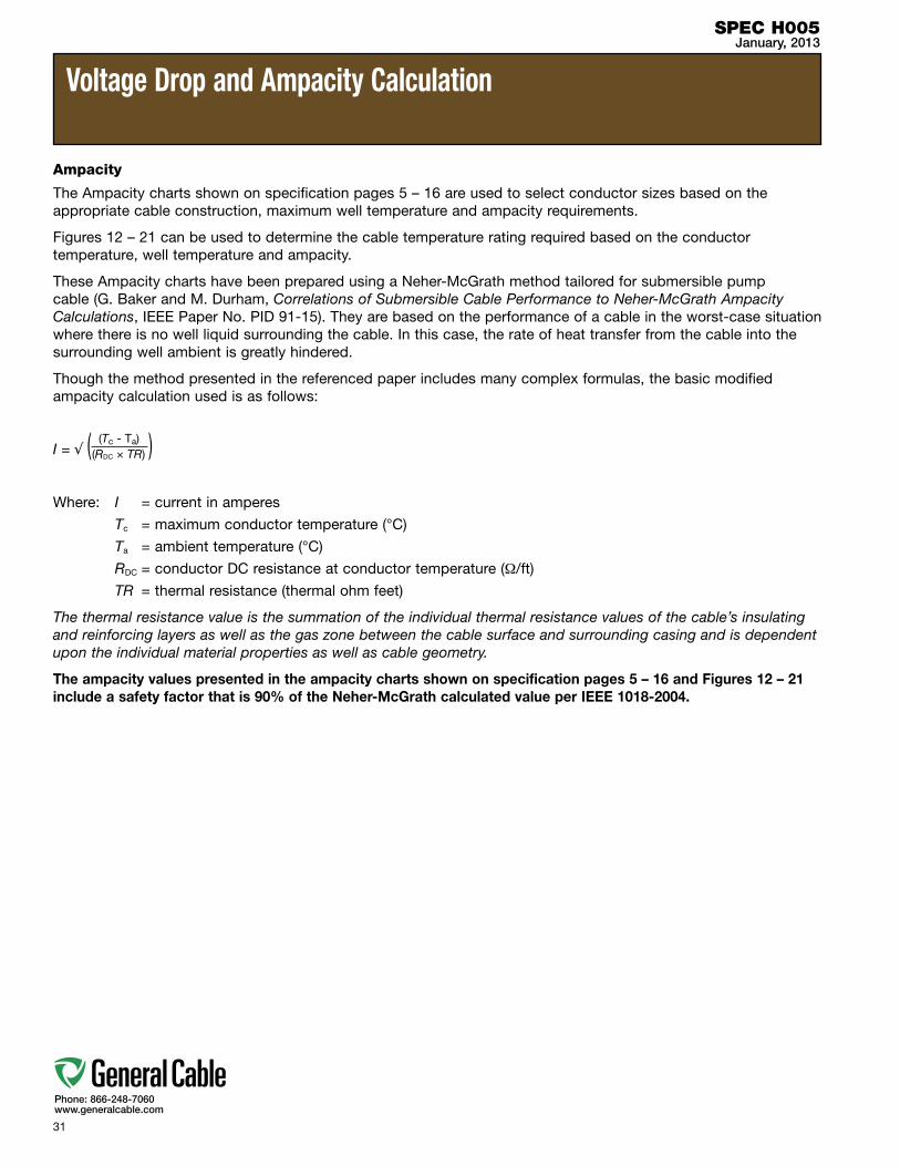
Voltage Drop and Ampacity Calculation
SPEC H005January, 2013
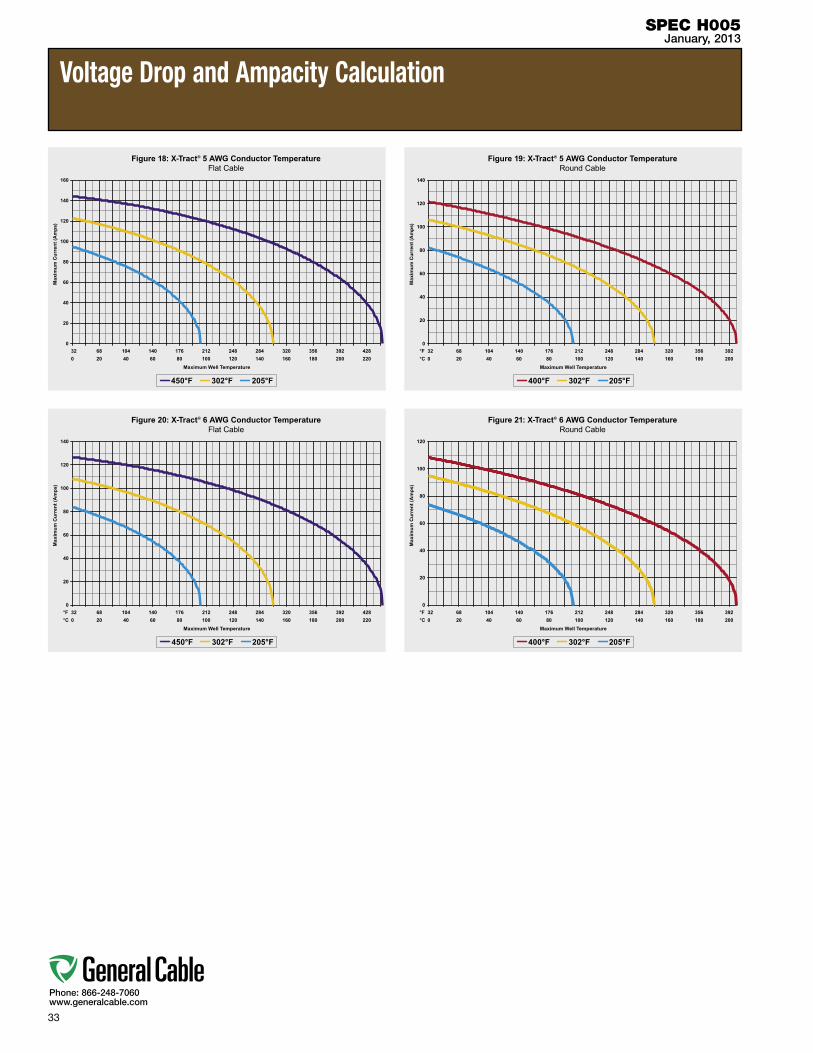
Ampacity
The Ampacity charts shown on specification pages 5 – 16 are used to select conductor sizes based on the appropriate cable construction, maximum well temperature and ampacity requirements.
Figures 12 – 21 can be used to determine the cable temperature rating required based on the conductor temperature, well temperature and ampacity.
These Ampacity charts have been prepared using a Neher-McGrath method tailored for submersible pump cable (G. Baker and M. Durham, Correlations of Submersible Cable Performance to Neher-McGrath Ampacity Calculations, IEEE Paper No. PID 91-15). They are based on the performance of a cable in the worst-case situation where there is no well liquid surrounding the cable. In this case, the rate of heat transfer from the cable into the surrounding well ambient is greatly hindered.
Though the method presented in the referenced paper includes many complex formulas, the basic modified ampacity calculation used is as follows:
I = √ ( (Tc - Ta) )
Where: I = current in amperes
Tc = maximum conductor temperature (°C)
Ta = ambient temperature (°C)
RDC = conductor DC resistance at conductor temperature (Ω/ft)
TR = thermal resistance (thermal ohm feet)
The thermal resistance value is the summation of the individual thermal resistance values of the cable’s insulating and reinforcing layers as well as the gas zone between the cable surface and surrounding casing and is dependent upon the individual material properties as well as cable geometry.
The ampacity values presented in the ampacity charts shown on specification pages 5 – 16 and Figures 12 – 21 include a safety factor that is 90% of the Neher-McGrath calculated value per IEEE 1018-2004.
(RDC × TR)

32
Phone: 866-248-7060www.generalcable.com
Voltage Drop and Ampacity Calculation
SPEC H005January, 2013
33
Phone: 866-248-7060www.generalcable.com
Voltage Drop and Ampacity Calculation
SPEC H005January, 2013
34
Phone: 866-248-7060www.generalcable.com
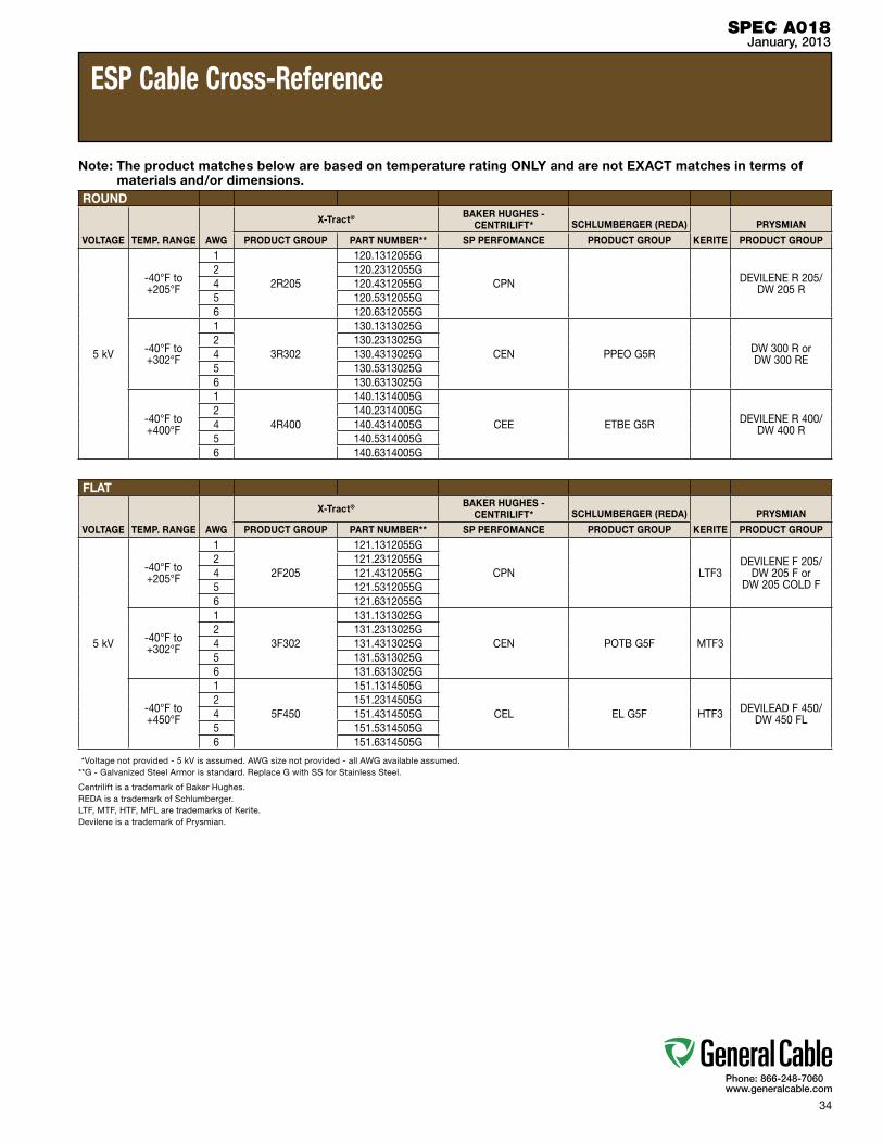
SPEC A018January, 2013
ESP Cable Cross-Reference
Note: The product matches below are based on temperature rating ONLY and are not EXACT matches in terms of materials and/or dimensions.
ROUND
VOLTAGE TEMP. RANGE AWG
X-Tract® BAKER HUGHES - CENTRILIFT* SCHLUMBERGER (REDA)
KERITE
PRYSMIAN
PRODUCT GROUP PART NUMBER** SP PERFOMANCE PRODUCT GROUP PRODUCT GROUP
5 kV
-40°F to +205°F
1
2R205
120.1312055G
CPN DEVILENE R 205/ DW 205 R
2 120.2312055G4 120.4312055G5 120.5312055G6 120.6312055G
-40°F to +302°F
1
3R302
130.1313025G
CEN PPEO G5R DW 300 R or DW 300 RE
2 130.2313025G4 130.4313025G5 130.5313025G6 130.6313025G
-40°F to +400°F
1
4R400
140.1314005G
CEE ETBE G5R DEVILENE R 400/ DW 400 R
2 140.2314005G4 140.4314005G5 140.5314005G6 140.6314005G
FLAT
VOLTAGE TEMP. RANGE AWG
X-Tract® BAKER HUGHES - CENTRILIFT* SCHLUMBERGER (REDA)
KERITE
PRYSMIAN
PRODUCT GROUP PART NUMBER** SP PERFOMANCE PRODUCT GROUP PRODUCT GROUP
5 kV
-40°F to +205°F
1
2F205
121.1312055G
CPN LTF3DEVILENE F 205/
DW 205 F or DW 205 COLD F
2 121.2312055G4 121.4312055G5 121.5312055G6 121.6312055G
-40°F to +302°F
1
3F302
131.1313025G
CEN POTB G5F MTF32 131.2313025G4 131.4313025G5 131.5313025G6 131.6313025G
-40°F to +450°F
1
5F450
151.1314505G
CEL EL G5F HTF3 DEVILEAD F 450/ DW 450 FL
2 151.2314505G4 151.4314505G5 151.5314505G6 151.6314505G
*Voltage not provided - 5 kV is assumed. AWG size not provided - all AWG available assumed.**G - Galvanized Steel Armor is standard. Replace G with SS for Stainless Steel.
Centrilift is a trademark of Baker Hughes.REDA is a trademark of Schlumberger.LTF, MTF, HTF, MFL are trademarks of Kerite.Devilene is a trademark of Prysmian.

35
Phone: 866-248-7060www.generalcable.com
SPEC A150September, 2010
Metric Conversion factors
To Convert From To Multiply By
Inches Millimeters 25.4 Millimeters Inches 0.03937
Inches Centimeters 2.54 Centimeters Inches 0.3937Length Feet Meters 0.3048 Meters Feet 3.2808
Kilofeet (1000 feet) Kilometers 0.3048 Kilometers Kilofeet (1000 feet) 3.2808
Square Inches Square Millimeters 645.16 Square Millimeters Square Inches 0.00155
Square Inches Square Centimeters 6.4516 Square Centimeters Square Inches 0.155
Area Square Inches Circular Mils 1,273,240 Circular Mils Square Inches 7.854 x 10⁻⁷
Circular Mils Square Millimeters 5.066 x 10⁴
Square Millimeters Circular Mils 1973.51
Square Feet Square Meters 0.0929 Square Meters Square Feet 10.764
Pounds Kilograms 0.4536 Kilograms Pounds 2.2046Weight Pound/Kilofeet Kilograms/Kilometer 1.4882 Kilograms/Kilometer Pounds/Kilofeet 0.6720
Ohms/Kilofeet Ohms/Kilometer 3.2808 Ohms/Kilometer Ohms/Kilofeet 0.3048
Microfarads/Kilofeet Microfarads/Kilometer 3.2808Electrical Microfarads/Kilometer Microfarads/Kilofeet 0.3048
Insulation Resistance: Megohms—Kilofeet Megohms—Kilometer 0.3048 Megohms—Kilometer Megohms—Kilofeet 3.2808
Pounds/Square Inch Kilo Pascal* 6.895
Mechanical Kilo Pascal* Pounds/Square Inch 0.1432 Pounds (force) Newtons 4.448
* 1 Pascal = 1 Newton/square meters

36
Phone: 866-248-7060www.generalcable.com
AWG (American Wire Gauge) to mm2 (Millimeters Squared) Conversion
SPEC A185September, 2010
AWG to mm² CONVERSION TABLE
AWG/kcmil [mm²]*
20 0.52
18 0.82
16 1.31
14 2.08
12 3.31
10 5.26
8 8.36
6 13.3
4 21.2
2 33.6
1 42.4
1/0 53.5
2/0 67.4
3/0 85.0
4/0 107
250 127
300 152
350 177
400 203
450 228
500 253
600 304
750 380
800 405
1000 507* Equivalent mm2 cross-sectional area
mm² to AWG CONVERSION TABLE
mm² [mm²]* AWG/kcmil
0.5 0.52 20
0.75 0.82 18
1.5 1.31 16
2.5 2.08 14
2.5 3.31 12
4 3.31 12
6 5.26 10
10 8.36 8
16 13.3 6
25 21.2 4
35 33.6 2
35 42.4 1
50 53.5 1/0
70 67.4 2/0
95 85.0 3/0
95 107 4/0
120 107 4/0
120 127 250
150 152 300
185 177 350
185 203 400
240 228 450
240 253 500
300 304 600
400 380 750
400 405 800
500 507 1000 Multiple AWG choices — consult responsible engineer for required ampacity
37
Phone: 866-248-7060www.generalcable.com
PARTNUMBER SPEC NUMBER PAGE
PARTNUMBER SPEC NUMBER PAGE
Part Number Index
IndexJanuary, 2013
120.1312055G ..................................SPEC 120 ............ 6120.1312055SS ................................SPEC 120 ............ 6120.2312055G ..................................SPEC 120 ............ 6120.2312055SS ................................SPEC 120 ............ 6120.4312055G ..................................SPEC 120 ............ 6120.4312055SS ................................SPEC 120 ............ 6120.5312055G ..................................SPEC 120 ............ 6120.5312055SS ................................SPEC 120 ............ 6120.6312055G ..................................SPEC 120 ............ 6120.6312055SS ................................SPEC 120 ............ 6121.1312055G ..................................SPEC 121 ............ 8121.1312055SS ................................SPEC 121 ............ 8121.2312055G ..................................SPEC 121 ............ 8121.2312055SS ................................SPEC 121 ............ 8121.4312055G ..................................SPEC 121 ............ 8121.4312055SS ................................SPEC 121 ............ 8121.5312055G ..................................SPEC 121 ............ 8121.5312055SS ................................SPEC 121 ............ 8121.6312055G ..................................SPEC 121 ............ 8121.6312055SS ................................SPEC 121 ............ 8130.1313025G ..................................SPEC 130 .......... 10130.1313025SS ................................SPEC 130 .......... 10130.2313025G ..................................SPEC 130 .......... 10130.2313025SS ................................SPEC 130 .......... 10130.4313025G ..................................SPEC 130 .......... 10130.4313025SS ................................SPEC 130 .......... 10130.5313025G ..................................SPEC 130 .......... 10130.5313025SS ................................SPEC 130 .......... 10130.6313025G ..................................SPEC 130 .......... 10130.6313025SS ................................SPEC 130 .......... 10131.1313025G ..................................SPEC 131 .......... 12131.1313025SS ................................SPEC 131 .......... 12131.2313025G ..................................SPEC 131 .......... 12131.2313025SS ................................SPEC 131 .......... 12131.4313025G ..................................SPEC 131 .......... 12131.4313025SS ................................SPEC 131 .......... 12131.5313025G ..................................SPEC 131 .......... 12131.5313025SS ................................SPEC 131 .......... 12131.6313025G ..................................SPEC 131 .......... 12131.6313025SS ................................SPEC 131 .......... 12
140.1314005G ..................................SPEC 140 .......... 14140.1314005SS ................................SPEC 140 .......... 14140.2314005G ..................................SPEC 140 .......... 14140.2314005SS ................................SPEC 140 .......... 14140.4314005G ..................................SPEC 140 .......... 14140.4314005SS ................................SPEC 140 .......... 14140.5314005G ..................................SPEC 140 .......... 14140.5314005SS ................................SPEC 140 .......... 14140.6314005G ..................................SPEC 140 .......... 14140.6314005SS ................................SPEC 140 .......... 14151.1314505G ..................................SPEC 151 .......... 16151.1314505SS ................................SPEC 151 .......... 16151.2314505G ..................................SPEC 151 .......... 16151.2314505SS ................................SPEC 151 .......... 16151.4314505G ..................................SPEC 151 .......... 16151.4314505SS ................................SPEC 151 .......... 16151.5314505G ..................................SPEC 151 .......... 16151.5314505SS ................................SPEC 151 .......... 16151.6314505G ..................................SPEC 151 .......... 16151.6314505SS ................................SPEC 151 .......... 16

Use your smartphone to view Interactive Catalog online
General Cable4 Tesseneer Drive Highland Heights, Kentucky 41076-9753 U.S.A.www.generalcable.com
Form No. INS-0106-R0113 43190
Telephone (866) 248-7060 Fax (859) 572-8463 International Telephone +1 859 572 8000 International Fax +1 859 572 8058


![COPPER TECHNOLOGY Copper data cables shielded nr. Description Product line List price [€/PU] Cu-Content [kg/km] Cu-base [€/100 kg] Packing unit [PkU] Price unit [PU]](https://static.documents.pub/doc/80x56/5b069bba7f8b9a56408be0c5/copper-technology-copper-data-cables-shielded-nr-description-product-line-list.jpg)


![Cable de Cobre Cu Características técnicas [ES] Copper Wire Cu · Technical Characteristics [EN] Le fil Cable de Cobre Cu Características técnicas [ES] Copper Wire Cu de cuivre](https://static.documents.pub/doc/80x56/5f5bd507c24c7e0edb5c86a1/cable-de-cobre-cu-caractersticas-tcnicas-es-copper-wire-cu-technical-characteristics.jpg)


