Electrical System—General 300-1 300 Electrical System - General General . . . . 300-1 To measure voltage . . 300-6 Voltage and Polarity . . . . 300-1 To check for a voltage drop . . 300-6 Wiring, Fuses, and Relays . ... 300-1 Checking for Continuity . . 300-7 Electrical System Safety Precautions . . . 300-1 Checking for Short Circuits . . 300-7 Electrical Test Equipment . . . . 300-2 To check for a short circuit using an ohmmeter . . 300-7 Wiring Diagrams. . . . . 300-2 To check for a short circuit using a voltmeter . . 300-8 Wiring Codes and Abbreviations . . . . 300-2 Using the Wiring Diagrams . . 300-4 TABLES Electrical Troubleshooting. . . . . 300-4 a. Terminal and Circuit Numbers . . 300-3 Checking for Voltage and Ground . . . . 300-4 b. Market Codes . . 300-4 GENERAL A brief description of the principal parts of the electrical system is presented here. Also covered here are general electrical system troubleshooting tips as well as instructions on using the Saab wiring diagrams. Fuse rating and color Red . . 10 amp Blue. . . 15 amp Yellow . . 20 amp Green . . 30 amp Voltage and Polarity Saab electrical systems are 12-volt direct current (DC) neg- ative-ground systems. A voltage regulator controls the system voltage at approximately the 12-volt rating of the battery. All circuits are grounded by direct or indirect connection to the negative (-} terminal of the battery. A number of ground connections throughout the car connect the wiring harness to chassis ground. These circuits are completed by the battery cable or ground strap between the body and the battery negative (-) terminal. The relays are electromagnetic switches that operate on low current to switch a high-current circuit on and off. Many of the relays are mounted on the fuse/relay panel in the engine compartment, although later models are equipped with additional auxiliary relay panels. For information on relay and fuse locations, see 371 Wiring Diagrams, Fuses and Relays. Electrical System Safety Precautions Please read the following warnings and cautions before doing any work on your electrical system. Wiring, Fuses, and Relays Nearly all parts of the wiring harness connect to components of the electrical system with keyed, push-on connectors that lock into place. Notable exceptions are the heavy battery cables and the alternator wiring. The wiring is color-coded for circuit identification. With the exception of the battery charging system, all electrical power is routed from the ignition switch or the battery through the fuse/relay panel, located in the right side of the engine compartment. Fuses prevent excessive current from damaging components and wiring. Fuses are color coded to indicate their different current capacities. WARNING • Some of the cars covered by this manual are equipped with a Supplemental Restraint System (SRS} that automatically deploys an airbag. The airbag unit uses an explosive device to electrically ignite a powerful gas. On cars so equipped, any work involving the steering wheel and SRS system should only be performed by an authorized Saab dealer. Performing repairs without disarming the SRS may cause serious personal injury. * On cars equipped with SRS (airbag) the ignition switch must be in the lock position before replacing fuses. If fuse no. 7 is removed with the ignition switch on, an SRS fault will be detected. !f the SRS warning light comes on, see an authorized Saab dealer.
Transcript
Electrical System—General 300-1
300 Electrical System - GeneralGeneral . . . . 300-1 To measure voltage . . 300-6
Voltage and Polarity . . . . 300-1 To check for a voltage drop . . 300-6
Wiring, Fuses, and Relays . . . . 300-1 Checking for Continuity . . 300-7
Electrical System Safety Precautions . . . 300-1 Checking for Short Circuits . . 300-7
Electrical Test Equipment . . . . 300-2 To check for a short circuit using anohmmeter .
. 300-7
Wiring Diagrams. . . . . 300-2 To check for a short circuit using avoltmeter .
. 300-8
Wiring Codes and Abbreviations . . . . 300-2
Using the Wiring Diagrams . . 300-4
TABLES
Electrical Troubleshooting. . . . . 300-4 a. Terminal and Circuit Numbers . . 300-3
Checking for Voltage and Ground . . . . 300-4 b. Market Codes . . 300-4
GENERAL
A brief description of the principal parts of the electricalsystem is presented here. Also covered here are generalelectrical system troubleshooting tips as well as instructionson using the Saab wiring diagrams.
Voltage and PolaritySaab electrical systems are 12-volt direct current (DC) neg-
ative-ground systems. A voltage regulator controls thesystem voltage at approximately the 12-volt rating of thebattery. All circuits are grounded by direct or indirectconnection to the negative (-} terminal of the battery. Anumber of ground connections throughout the car connectthe wiring harness to chassis ground. These circuits arecompleted by the battery cable or ground strap between thebody and the battery negative (-) terminal.
The relays are electromagnetic switches that operate onlow current to switch a high-current circuit on and off. Manyof the relays are mounted on the fuse/relay panel in theengine compartment, although later models are equippedwith additional auxiliary relay panels. For information onrelay and fuse locations, see 371 Wiring Diagrams, Fusesand Relays.ElectricalSystemSafetyPrecautions
Please read the following warnings and cautions beforedoing any work on your electrical system.
Wiring,Fuses,and Relays
Nearly all parts of the wiring harness connect tocomponents of the electrical system with keyed, push-onconnectors that lock into place. Notable exceptions arethe heavy battery cables and the alternator wiring. Thewiring is color-coded for circuit identification.
With the exception of the battery charging system, allelectrical power is routed from the ignition switch or thebattery through the fuse/relay panel, located in the rightside of the engine compartment. Fuses prevent excessivecurrent from damaging components and wiring. Fusesare color coded to indicate their different currentcapacities.
WARNING
• Some of the cars covered by this manual areequipped with a Supplemental Restraint System(SRS} that automatically deploys an airbag. Theairbag unit uses an explosive device to electricallyignite a powerful gas. On cars so equipped, anywork involving the steering wheel and SRS systemshould only be performed by an authorized Saabdealer. Performing repairs without disarming theSRS may cause serious personal injury.* On cars equipped with SRS (airbag) the ignitionswitch must be in the lock position before replacingfuses. If fuse no. 7 is removed with the ignitionswitch on, an SRS fault will be detected. !f the SRSwarning light comes on, see an authorized Saabdealer.
300-2 Electrical System—GeneralWARNING
• The ignition system of the car operates at lethalvoltages. People with pacemakers or weak heartsshould not expose themselves to the ignitionsystem. Extra caution must be taken when workingon the ignition system orwhen servicing the enginewhile it is running or the key is on. See 340 IgnitionSystem for additional ignition system warnings andcautions.• Before operating the starter without starting theengine (as when making a compression test),disable the ignition system as described in 340Ignition System.• Keep hands, clothing and other objects clear ofthe radiator cooling fan when working on a warmengine. The fan may start at any time, even whenthe ignition is switched off.
Electrical Test Equipment
Many of the electrical tests described in this manual callfor measuring voltage, current or resistance using adigital multimeter (DMM). Digital meters are preferred forprecise measurements and for electronics work becausethey are generally more accurate than analog meters.The numerical display is also less likely to be misread,since there is no needle position to be misinterpreted byreading at an angle.
An LED test light is a safe, inexpensive tool that can beused to perform many simple electrical tests that wouldotherwise require a multimeter. The LED indicates whenvoltage is present between any two test-points in acircuit.
CAUTION
• Always turn off the engine and remove thenegative (-) battery cable before removing anyelectrical components.• Connect and disconnect ignition system wires,multiple connectors, and ignition test equipmentleads only while the ignition is off.• Do not disconnect the battery while the engine isrunning.• Do not quick-charge the batlery {for booststarting) for longer than one minute, and do notexceed 16.5 volts at the battery with the boostingcables attached. Wait at least one minute beforeboosting the battery a second time.• Do not use a test lamp that has a normalincandescent bulb to test circuits containingelectronic components. The high electricalconsumption of these test lamps may damage thecomponents.• Many of the solid-state modules are staticsensitive. Static discharge will permanentlydamage them. Always handle the modules usingproper static prevention equipment and techniques.• To avoid damaging harness connectors or relaypanel sockets, use jumper wires with flat-bladeconnectors that are the same size as the connectoror relay terminals.• Always switch a test meter to the appropriatefunction and range before making test connections.• Do not try to start the engine of a car which hasbeen heated above 176°F(80:)C), (for example, in apaint drying booth) until allowing it to cool to normaltemperature.• Disconnect the battery before doing any electricwelding on the car.• Do not tow a car suspected of having a defectiveignition system without first disconnecting theignition control unit.• Do not wash the engine while it is running, oranytime the ignition is switched on.
CAUTION
• Choose test equipment carefully. Use a meterwith at least 10 megohm input impedance, or anLED test light. An analog meter (swing-needle) or atest light with a normal incandescent bulb maydraw enough current to damage sensitive electroniccomponents.• An ohmmeter must not be used to measureresistance on solid state components such ascontrol units ortime delay relays.• Always disconnect the battery before makingresistance (ohm) measurements on the circuit.
WIRING DIAGRAMSThe wiring diagrams shown in 371 Wiring Diagrams,
Fuses and Relays have been specially designed toenable quick and efficient diagnosis and troubleshootingof electrical malfunctions.
Each electrical sub-system, such as the ignitionsystem, the hazard warning lights, etc., is describedindividually and a separate wiring diagram is shown foreach sub-system on the car. Each wiring sub-systemconsists of a spread that includes a brief description ofthe circuit operation, fault tracing, a list of all thecomponents used in the circuit along with their location inthe car, and the wiring diagram(s) applicable to thatcircuit.WiringCodesandAbbreviations
A tremendous amount of information is included ineach wiring diagram if you know how to read them. Forexample, you will notice that all electrical components,connectors, fuses, and ground locations are identifiedusing a unique number. Each of these numberscorresponds to a particular part in the circuit. A completelisting of these component numbers, their identificationsand locations is given in 371 Wiring Diagrams, Fusesand Relays.
Electrical System—General 300-3All wire colors in the diagrams are abbreviated.
Combined color codes indicate a multi-colored wire. Forexample the code BL/RD indicates a Blue wire with a Redstripe. Wire color abbreviation are listed below.Immediately following the wire color is the nominal cross-sectional area of the wire given in mm2.NOTESometimes the color of an installed wire may bedifferent than the one on the wiring diagram. Don'tbe concerned, just be sure to confirm that the wireconnects to the proper terminals.
Wire color codesBL or B U . . . BlueBR or BN. . . BrownGL or YE. . . YellowGN . . GreenG R o r G Y . . GrayOG . . OrangeR A o r P K . . .PinkRD. . . RedSV or B K . . BlackVL . . .VioletVT or WH . . White
Most terminals are identified by numbers on thecomponents and harness connectors. The terminalnumbersfor major electrical connections are shown in thediagrams. Though many terminal numbers appear onlyonce, several other numbers appear in numerous placesthroughout the electrical system and identify certain typesof circuits. Several of the most common circuit numbersare listed below in Table a.Table a. Terminal and Circuit Numbers
Number Circuit description
1 Low voltage switched (1 ) terminal of coil
4 High voltage center terminal of coil
+X Originates at ignition switch. Suppliespower when the ignition switch is in thePARK, RUN, or START position
S Originates at ignition switch. Suppliespower whenever the key is in the ignitionswitch, (power in LOCK, PARK, RUN, orSTART position)
15or +15 Originates at ignition switch. Suppliespower when ignition switch is in RUN orSTART position
30 or +30 Battery positive (+) voltage. Suppliespower whenever battery is connected.(Not dependent on ignition switchposition, unfused)
31 Ground, battery negative (-) terminal
Table a. Terminal and Circuit Numbers (continued)
Number Circuit description50 or +50 Supplies power from battery to starter
solenoid when ignition switch is in STARTposition only
+54 Originates at ignition switch. Suppliespower when ignition switch is in the RUNposition only
85 Ground side (-) of relay coil86 Power-in side (+) of relay coil87 Relay change-over contactD Alternator warning light and field
energizing circuitAdditional abbreviations shown in the wiring diagramsare given below
AbbreviationA B S . . antilock brakesAC . . air conditioningAIC . . automatic idle controlA R C . . automatic performance control
(turbo models)AUT . . .automatic transmissionCAB. . . cabriolet (convertible)cc . . cruise controlCONV . . convertibleECU . . electronic control unitEZK . . electronic ignition with knock controlI . . fuel injection engineLH . . fuel injection systemL H D . . left hand driveL H F . . .left hand, frontL H R . . left hand, rearLHS . . left hand, sideM . . designation for model year, i.e.
M89for 1989 modelMAN . . .manual transmissionP . . .passengerRHD. . . .right hand driveR H F . . right hand, frontRHR. . . . right hand, rearR H S . . .right hand, sideSRS . . supplemental restraint system
Airbag (see warnings in text)T . . turboTSI . timing service instrument (test2-D . . 2-door sedan3-D . . 3-door hatchback4-D . . 4-door sedanUS . . . . Cars for sale in the UnitedC A . . Cars for sale in CanadaUC . . Cars for sale in California
continued
300-4 Electrical System—GeneralCAUTIONMany of the wiring diagrams are applicable to carsdelivered to other world markets served by Saab.At times, there may be certain parts of the diagramthat are applicable only to these markets. Thismanual covers only Saab cars delivered to theUnited States (US), California (UC), and Canada(CA). Abbreviations other than US, UC, and CAfound on a particular diagram should be ignored.For example the abbreviation "ME" is for cars soldin the Middle East. Table b is a complete list of themarket codes.
Table b. Market Codes
Marketcodes
Market Marketcodes
Market
AT Austria FR France
AU Australia GB Great Britain
BE Belgium GR Greece
CA Canada IS Iceland
CH Switzerland IT Italy
DE Germany JP Japan
DK Denmark ME Middle East
ES Spain NL Netherlands
EU Europe NO Norway
FE Far East SE Sweden
Fl Finland US USA
Using the Wiring DiagramsAn example of a wiring diagram is shown below
together with an explanation of the symbols used inthe diagram. See Fig.1.
NOTE• Unless specified otherwise, switches and relaysare shown in the rest or de-energized position.• Throughout the wiring diagrams, a fuse is showntogether with the designation 22A. This 22A codeis the component number for the fuse holder in thefuse/relay panel and should not be confused withthe fuse rating or the fuse position.• Designations such as +30, +15. +54 are positivevoltage supplies, usually found at the top of eachcircuit. Each number represents when voltage ispresent in the circuit. For example, +30 is live at alltimes (unfused) and +15 is live when the key is inthe run or start position. See above for a listing ofthe common terminal and circuit numbers.
ELECTRICAL TROUBLESHOOTING
Four things are required for current to flow in anyelectrical circuit: a voltage source, wires orconnections to transport the voltage, a consumer ordevice that uses the electricity, and a connection toground. Most problems can be found using only adigital multimeter (volt/ohm/amp meter) to check forvoltage supply, for breaks in the wiring (infiniteresistance/no continuity), or for a path to ground thatcompletes the circuit.
Electric current is logical in its flow, always movingfrom the voltage source toward ground. Keeping thisin mind, electrical faults can be located through aprocess of elimination. When troubleshooting acomplex circuit, separate the circuit into smallerparts. The general tests outlined below may behelpful in finding electrical problems. The informationis most helpful when used with the wiring diagrams.
Be sure to analyze the problem. Use the wiringdiagrams to determine the most likely cause of theproblem. Get an understanding of how the circuitworks by following the circuit from ground back to thepower source.
You will find the problem if you follow a simple andlogical step-by-step procedure. Test portions of thecircuit at one time, starting with the area orcomponent most likely to be at fault. Test first atpoints that you can reach most easily. When you findthe cause of the problem, make the repair. Use ap-propriate tools and procedures. As a final check, testthe functions of the circuit that you worked on.
When making test connections at connectors andcomponents, use care to avoid spreading ordamaging the connectors or terminals. Someelectrical tests may require jumper wires totemporarily bypass components or connections in thewiring harness. When connecting jumper wires, useblade connectors at the wire ends that match the sizeof the terminal being tested. The delicate internalcontacts are easily spread apart, and this can causeintermittent or faulty connections that can lead tomore problems.
Checking for Voltage and GroundChecking for the presence of voltage or ground is
usually the first step in troubleshooting a problemcircuit. When checking for voltage, a digital voltmeteror LED test light should be used, for example, if aparking light does not work, check for voltage at thebulb socket will quickly determine if the circuit isfunctioning properly or if the bulb itself is faulty. Ifvoltage and ground are found at the socket, then thebulb is most likely faulty.
Another valuable troubleshooting technique is avoltage drop test. This is a good test to make ifcurrent is flowing through the circuit, but the circuit isnot operating correctly. Sluggish wipers or dimheadlights are examples of this. A voltage drop testwill help to pinpoint a corroded ground strap or afaulty switch. Normally, there should be less than 1volt drop across most wires or closed switches. Avoltage drop across a connector or short cableshould not exceed 0.5 volts.
ELECTRICAL TROUBLESHOOTING
Fig. 1. Example of how to read Saabwiring diagrams. Electrical System—General 300-5
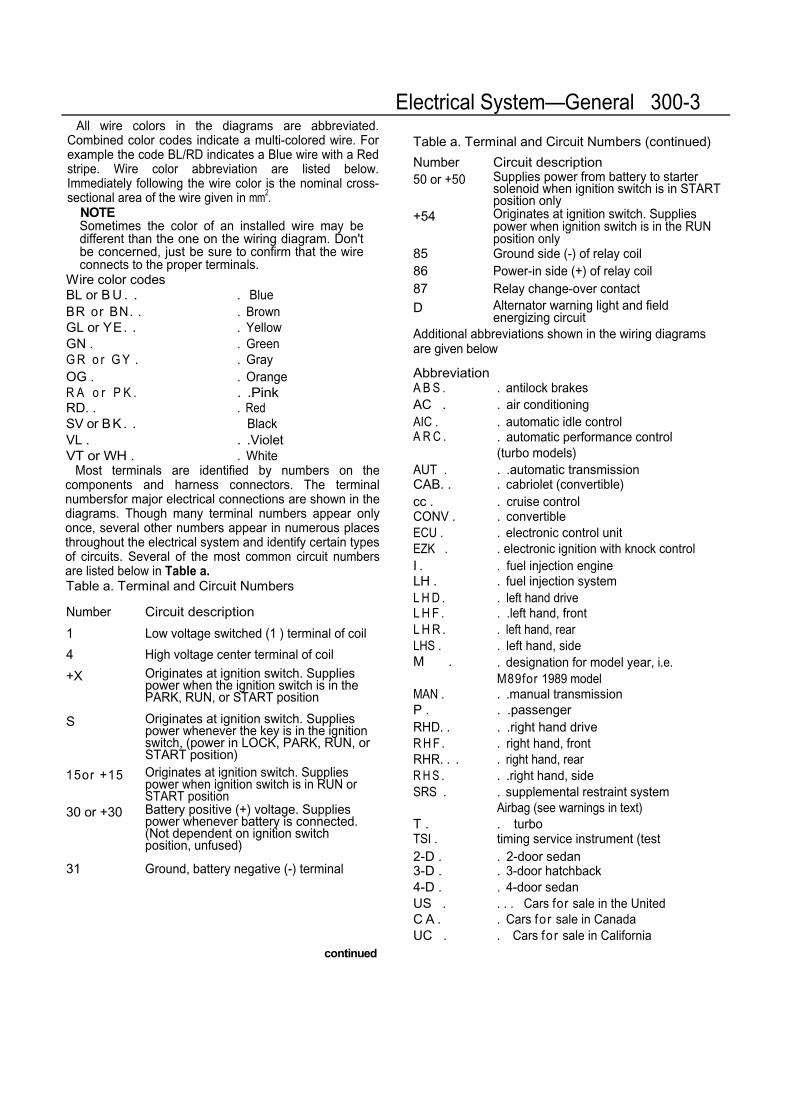
300-6 Electrical System—GeneralThe wires, connectors, and switches that carry
current are designed with very low resistance so thatcurrent flows with a minimum loss of voltage. Avoltage drop is caused by higher than normalresistance in a circuit. This additional resistanceactually decreases or stops the flow of current. Avoltage drop can be noticed by problems rangingfrom dim headlights to sluggish wipers. Somecommon sources of voltage drops are faulty wires orswitches, dirty or corroded connections or contacts,and loose or corroded ground wires and ground con-nections.
Voltage drop can only be checked when current isrunning through the circuit, such as by operating thestarter motor or turning on the headlights. Making avoltage drop test requires measuring the voltage inthe circuit and comparing it to what the voltageshould be. Since these measurements are usuallysmall, a digital voltmeter should be used to ensureaccurate readings. If a voltage drop is suspected, turnthe circuit on and measure the voltage at the circuit'sload.
NOTE
• A voltage drop test is generally more accuratethan a simple resistance check because theresistances involved are often too small tomeasure with most ohmmeters. For example, aresistance as small as 0.02 ohms would resultsin a 3 Volt drop in a typical 150 amp startercircuit. (150 amps x 0.02 ohms =3 volts).• Keep in mind that voltage with the key on andvoltage with the engine running are not thesame. With the ignition on and the engine off(battery voltage), voltage should be approxi-mately 12.6 volts. With the engine running(charging voltage), voltage should beapproximately 14.0 volts. Measure voltage atthe battery with the ignition on and then with theengine running to get exact measurements.
To measure voltage1. Connect the voltmeter negative lead to a
reliable ground point on the car. The negative (-) battery terminal is always a good a groundpoint.
2. Connect the voltmeter positive lead to the pointin the circuit you wish to measure. See Fig. 2. Ifa reading is obtained, current is flowing throughthe circuit.
NOTE
The voltage reading should not deviate morethan 1 volt less than the voltage at the battery. Ifthe voltage is less than this, there is probably afault in the circuit, such as a corroded connectoror a loose ground wire.
Fig. 2. Voltmeter being used to check for voltage,
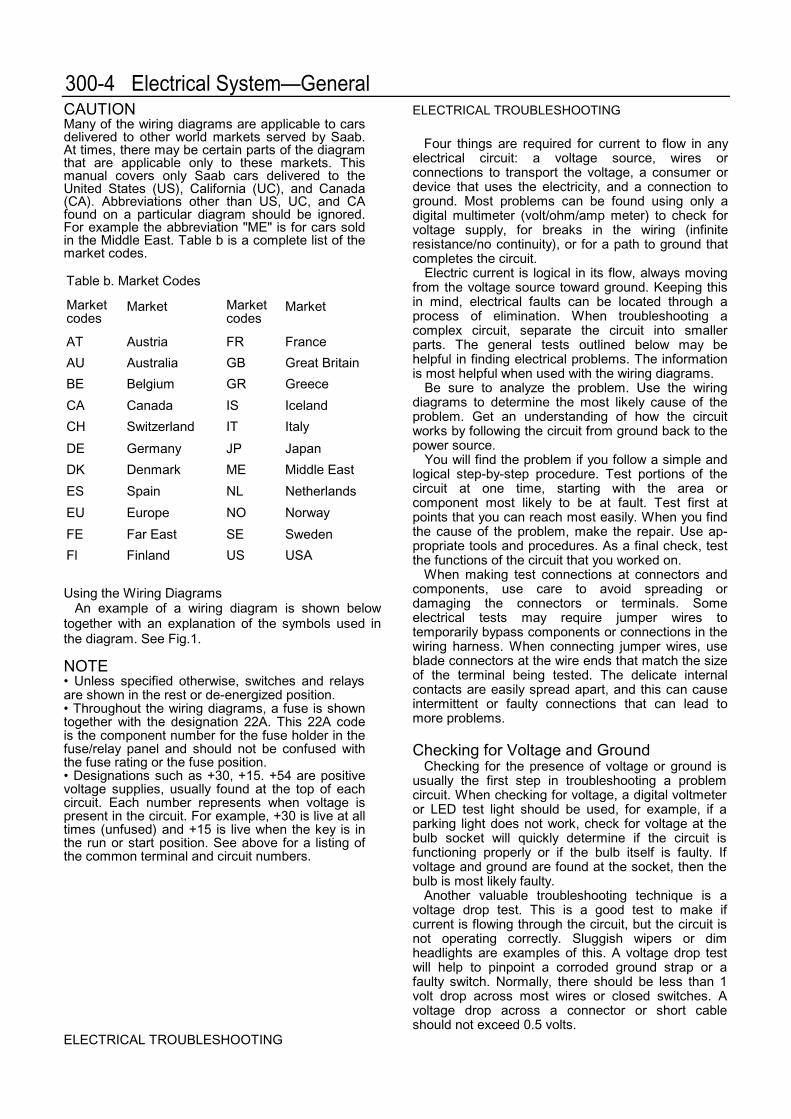
2. Connect the voltmeter negative lead to theother end of the cable or switch being tested.See Fig. 3.
Fig. 3. Voltmeter being used to check for voltagedrop.
To check for a voltage drop1. Connect the voltmeter positive lead to the
positive (+) battery terminal or a positive powersupply close to the battery source.
3. With the power on and the circuit working, themeter shows the voltage drop (the differencebetween the two points). This value should notexceed 1 volt.
ELECTRICAL THOUBLESHOOTING
Electrical System—General 300-7NOTE
The maximum voltage drop in an automotivecircuit, as recommended by the Society ofAutomotive Engineers (SAE), is as follows: 0Volts for small wire connections; 0.1 Volts forhigh current connections; 0.2 Volts for highcurrent cables; and 0.3 Volts for switch orsolenoid contacts. On longer wires or cables,the drop may be slightly higher. In any case, avoltage drop of more than 1.0 Volt usuallyindicates a problem.
Checking for Continuity
The continuity lest can be used to check a circuit orswitch. Because most automotive circuits aredesigned to have little or no resistance, a circuit orpart of a circuit can be easily checked for faults usingan ohmmeter. An open circuit or a circuit with highresistance will not allow current to flow. A circuit withlittle or no resistance allows current to flow easily.
CAUTION
Do not use an analog (swing-needle) ohmmeterto check circuit resistance or continuity on anyelectronic (solid-state) components. The internalpower source used in most analog meters candamage solid state components. Use only ahigh quality digital ohmmeter having high inputimpedance when checking electroniccomponents.
When checking continuity, the ignition should beoff. On circuits that are powered at all times, thebattery should be disconnected. Using theappropriate wiring diagram, a circuit can be easilytested for faulty connections, wires, switches, relays,and engine sensors by checking for continuity. Fig. 4shows continuity lest being made on a brake lightswitch.
Checking for Short Circuits
A short circuit is exactly what the name implies.The circuit takes a shorter path than it was designedto take. The most common short that causesproblems is a short to ground where the insulation ona positive (+} wire wears away and the metal wire isexposed. When the wire rubs against a metal part ofthe car or other ground source, the circuit is shortedto ground. If the exposed wire is live (positive batteryvoltage), a fuse will blow and the circuit may possiblybe damaged.
Shorts to ground can be located with an ohmmeteror a voltmeter. Short circuits are often difficult tolocale and may vary in nature. Short circuits can befound using a logical approach based on the currentpath.
Rg. 4. Brake light switch being tested for continuity.
With brake pedal in rest position (switch open) thereis no continuity (infinite ohms), With the pedaldepressed (switch closed) there is continuity (zeroohms).
CAUTION
• On circuits protected with large fuses (25 ampand greater), the wires or circuit componentsmay be damaged before the fuse blows. Alwayscheck for damage before replacing fuses of thisrating.• When replacing blown fuses, use only fuseshaving the correct rating. Always confirm thecorrect fuse rating printed on the fuse/relaypanel cover.
To check for a short circuit using anohmmeter
1. Remove the blown fuse from the circuit anddisconnect the cables from the battery.
2. Disconnect the harness connector from thecircuit's load or consumer.
3. Using an ohmmeter, connect one test lead tothe load side of the fuse terminal (terminalleading to the circuit) and the other test lead toground. See Fig. 5.
4. If there is continuity to ground, there is a shortto ground.
ELECTRICALTROUBLESHOOTING
300-8 Electrical System—General
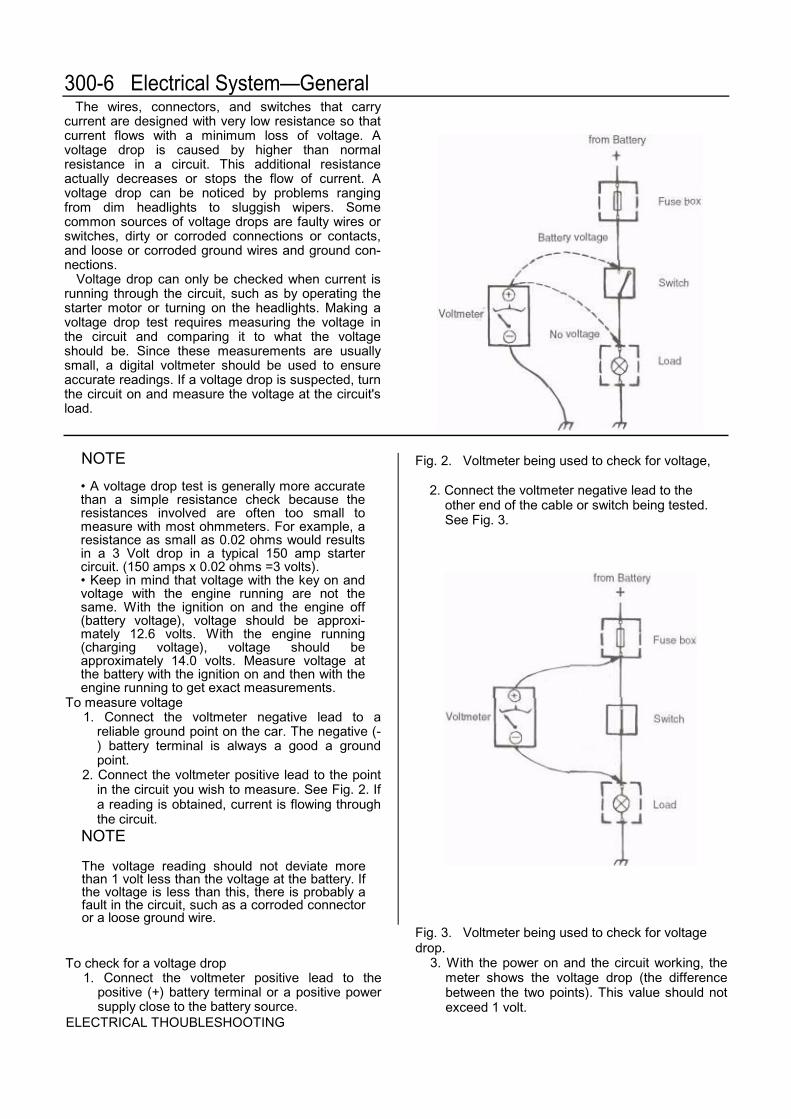
Fig. 5. Ohmmeter being used to find short circuit.
5. If there is no continuity, work from the wireharness nearest to the fuse/relay panel andmove or wiggle the wires while observing themeter. Continue to move down the harness untilthe meter displays a reading. This is thelocation of the short to ground.
Visually inspect the wire harness at this point forany faults. If no faults are visible, carefully slice openthe harness cover or the wire insulation for furtherinspection. Repair any faults found.
To check for a short circuit using a voltmeter
1. Remove the blown fuse from the circuit.2. Disconnect the harness connector from the
circuit's load or consumer.
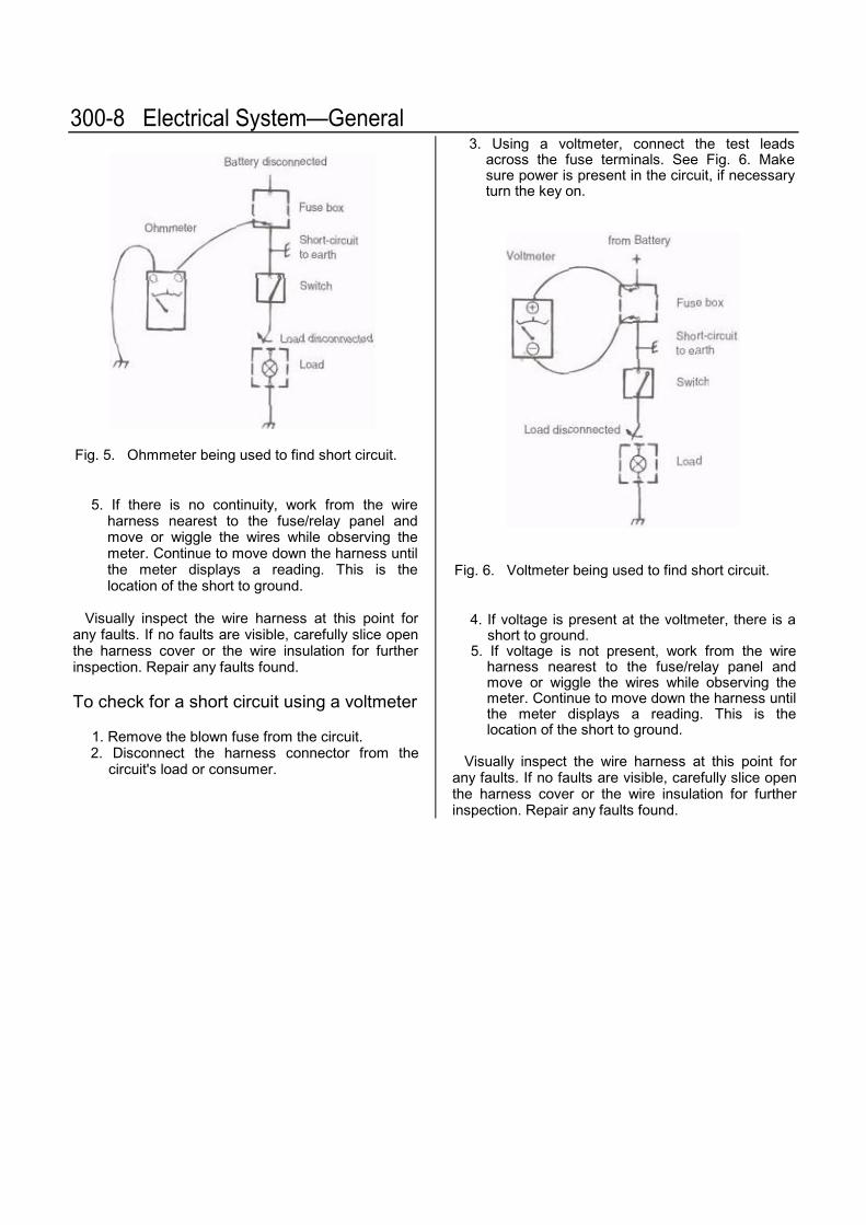
3. Using a voltmeter, connect the test leadsacross the fuse terminals. See Fig. 6. Makesure power is present in the circuit, if necessaryturn the key on.
Fig. 6. Voltmeter being used to find short circuit.
4. If voltage is present at the voltmeter, there is ashort to ground.
5. If voltage is not present, work from the wireharness nearest to the fuse/relay panel andmove or wiggle the wires while observing themeter. Continue to move down the harness untilthe meter displays a reading. This is thelocation of the short to ground.
Visually inspect the wire harness at this point forany faults. If no faults are visible, carefully slice openthe harness cover or the wire insulation for furtherinspection. Repair any faults found.
Open-Circuit Voltage Test . . 311-1 a. Open-Circuit Voltage and Battery Charge . .311-1
Load Voltage Testing . 311-2 b. Battery Charging Specifications . .311-2
GENERAL
The six-cell, 12-volt lead-acid battery capacity israted by ampere/hours (Ah) and cold cranking amps(CCA). The Ah rating is determined by the averageamount of current the battery can deliver over timewithout dropping below a specified voltage. The CCArating is determined by the battery's ability to deliverstarting current at 0° (-18°C). The original battery in-stalled is rated at 62 Ah and is located in the enginecompartment, behind the right headlight assembly.
Maintenance consists of keeping the battery andterminals clean and keeping the connections tight.After cleaning, alight coating of petroleum jelly shouldbe spread on the terminals. Inspect the batterycables for chafing and deterioration of the insulationdue to high heat.
For general information on troubleshootingelectrical systems see 300 Electrical System—General. For information on battery wiring see 371Wiring Diagrams, Fuses and Relays.
WARNING
• Wear goggles, rubber gloves, and a rubberapron when working with battery electrolyte.Electrolyte contains sulfuric acid and can causeskin irritation and burning. If electrolyte is spilledon your skin or clothing, flush the area at oncewith large quantities of water. If electrolyte getsinto your eyes, bathe them with large quantitiesof clean water for several minutes and call aphysician.• Batteries that are being charged or are fullycharged give off explosive hydrogen gas. Keepsparks and open flames away. Do not smoke.
CAUTION
• Do not quick-charge the battery (for booststarting) for longer than one minute, and do notexceed 16.5 volts at the battery with theboosting cables attached. Wait at least oneminute before boosting the battery a secondtime.• Always disconnect the negative (-) batterycable first and reconnect it last. Cover thebattery post with an insulating materialwhenever the terminal is removed.• When boost starting the car using jumpercables, be careful not to reverse the batteryconnections. Even a momentary connection willdamage the alternator.
BATTERY TESTING
Battery testing determines the state of batterycharge. The most common methods are open-circuitand load voltage testing. Batteries that have fillercaps can also be tested by checking the specificgravity of the electrolyte. The specific gravity testchecks the amount of acid in the electrolyte as anindication of battery charge. Inexpensive specificgravity testers are available at most auto supplystores.
OPEN-CIRCUIT VOLTAGE TEST
An open-circuit voltage test checks battery voltageby connecting an accurate digital voltmeter to thebattery posts after disconnecting the battery groundcable. Before making an open-circuit voltage test ona battery, first load the battery with 15 amps for oneminute, for example by turning on the headlightswithout the engine running. Open-circuit voltagelevels and their corresponding percentages of chargeare in Table a.
CAUTION• Do not disconnect the battery when theengine is running. The alternator will bedamaged.• Replace batteries if the case is cracked orleaking. Electrolyte can damage the car. Ifelectrolyte is spilled, clean the area with asolution of baking soda and water.• Always allow a frozen battery to thaw beforeattempting (o recharge it.• Always disconnect the battery terminals duringbattery recharging. This will prevent damage tosolid-state components.
Table a. Open-Circuit Voltage and Battery Charge
Open -circuit voltage State of charge
12.6 V or more Fully charged12.4V 75% charged12.2V 50% charged12.0V 25% charged11.7V or less Fully discharged
Battery 311-1
The battery is in satisfactory condition if the open-circuit voltage is at least 12.4 volts. If the open-circuitvoltage is at this level or above, but the battery stilllacks power for starting, make a load voltage test todetermine the battery's service condition. If the open-circuit voltage is below 12.4 volts, recharge thebattery. If the battery cannot be recharged to at least75%, it should be replaced.
Load Voltage TestingA load voltage battery test is made by connecting a
specific resistive load to the battery terminals andthen measuring voltage. The test requires a specialtester and can generally be performed quickly andinexpensively by an authorized Saab dealer orqualified repair facility. The battery should be fullycharged for the most accurate results. If theequipment is available, disconnect the negative (-)battery cable. Then apply a 200 Amp load for 15seconds and measure the battery's voltage. If thevoltage is below that listed, the battery should bereplaced.
Battery chargingDischarged batteries can be recharged using a
battery charger, but a battery can never be chargedto a voltage in excess of that which it is capable ofproducing electro-chemical-ly. Prolonged chargingcauses gassing that will evaporate the electrolyte toa level that can damage the battery.
Always read and follow the instructions provided bythe battery charger's manufacturer. Do not use acharger if the instructions are not available. Table blists charging rates and times that should be followedwhen charging batteries.
WARNINGThe gasses given off by the battery duringcharging are explosive. Do not smoke. Keepopen flames away from the top of the battery,and prevent electrical sparks by turning off thebattery charger before connecting ordisconnecting it.
WARNINGAlways wear protective goggles and clothingwhen performing a load test.
CAUTIONAlways disconnect a battery cable when using abattery charger. This will prevent damage tosolid-state components.
Battery load test minimum* (200 amp load for 15 seconds)9.6V at 80°F(27°C)9.5 V at 60°F(16°C)9.3V at 40°F(4°C)8.9V at 20°F(-7°C)8.5V at O°F(-18°C)
If the battery quickly becomes discharged, theremay be a fault in the charging system or in theelectrical system. See 321 Alternator and ChargingSystem for charging system tests. On all models, becertain that the appropriate heat shields are securelyattached to the battery.
Table b. Battery Charging SpecificationsCharging rate (low-maintenance batteries)
Specificgravity
Approximatecharging time
1.150 or less 1 hour1.150 to1.175
3/4 hour
1.175 to1.200
1/2 hour
Fast charge (at 80% to90% of battery'scapacity, example: 44to 50 amperes for a 55-ampere hour battery)
Charging System Quick-check . .321-1 To replace regulator brushes . . 321-3
GENERAL
The charging system consists of a belt-driven 14-volt alternator and a voltage regulator. The voltageregulator, which is mounted on the alternator, alsoserves as the alternator brush holder. The chargingsystem provides the current necessary to keep thebattery charged and to operate the car electricalaccessories.
To prevent damage to the alternator or regulatorwhen making tests or repairs, make all connectionswith negative (-) to negative, and positive (+) topositive. Even momentary contact with a conductorof the wrong polarity can damage the alternator'sdiodes.
Please read the following cautions before doingany work on the charging system or alternator.
CAUTION
• Never operate the engine with the batterydisconnected. Never operate the alternator withits output terminal (B+ or 30) disconnected andthe other terminals connected. Never short,bridge, or ground any terminals of the chargingsystem.• Always disconnect the negative (-} batterycable before removing the alternator. This willprevent an accidental short from one of thealternator terminals.• Do not reverse the polarity of the battery.Damage to the alternator will result.• Always disconnect both battery cables beforedoing any electric (arc) welding to the car.
CHARGING SYSTEM TROUBLESHOOTING
Charging system trouble is indicated by anilluminated alternator warning light on the instrumentpanel, or by an under-or overcharged battery.
The alternator generates electrical current byelectrical induction. When the engine is running, partof the current it produces energizes itselectromagnetic field. When starting, some othercurrent must be provided to initially energize the
field and begin the current generating process. Thiscurrent is provided by the battery through thealternator warning light in the instrument cluster. Ifthe lamp burns out, the alternator will not charge thebattery properly.
CHARGING SYSTEM QUICK-CHECK
As a quick-check, measure the voltage across thebattery terminal with the key off and then again withthe engine running. The battery voltage should beapproximately 12.6 with key off and 14.0 with theengine running. If the voltage does not increase whenthe engine is running, there is fault in the chargingsystem.
TO TEST CHARGING SYSTEM
1. Inspect the V-belts and make sure they aretight. Make sure the battery is fully charged, asdescribed in 311 Battery.
2. Check the charge warning lamp. On 1987 andlater cars, check that the ignition switch relaycloses when the key is turned on. See 371Wiring Diagrams, Fuses and Relays for acomplete listing of fuse and relay locations.
NOTE
* The charging system warning light shouldcome on when the key is on and go out whenthe car is started. Turning the key on is a testthat checks the warning light circuit to thealternator. If the light does not come on whenthe key is turned on, check the light bulb andthe wiring to the bulb using the appropriatewiring diagram before making any more tests.Wiring diagrams can be found in 371 WiringDiagrams, Fuses and Relays.• When replacing the charging system warningbulb, be sure to use the correct 2.0 wattreplacement bulb. A similar 1.2 watt bulb (withblack socket base) will also fit in this location. Ifthe smaller bulb is installed, the battery will notcharge correctly at idle. The light will also go outat a higher rpm. See an authorized Saab partsdepartment for additional information.
321-2 Alternator and Charging System
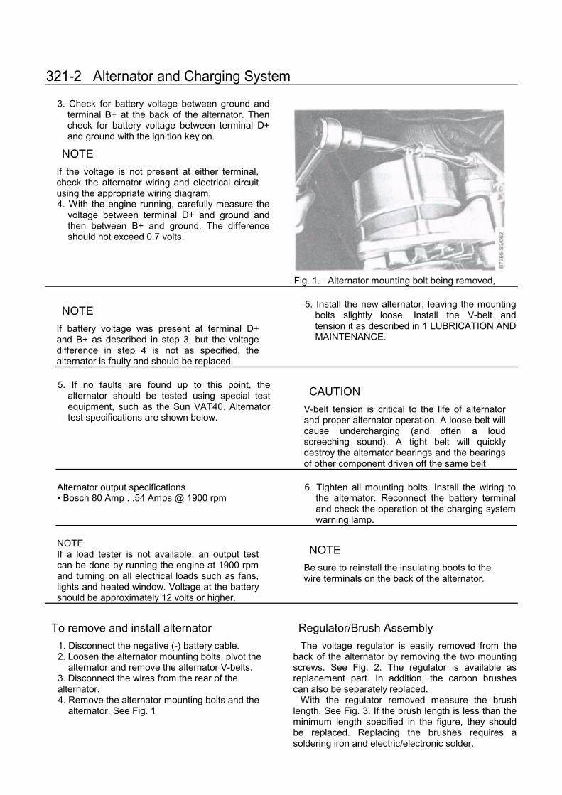
3. Check for battery voltage between ground andterminal B+ at the back of the alternator. Thencheck for battery voltage between terminal D+and ground with the ignition key on.
NOTE
If the voltage is not present at either terminal,check the alternator wiring and electrical circuitusing the appropriate wiring diagram.4. With the engine running, carefully measure the
voltage between terminal D+ and ground andthen between B+ and ground. The differenceshould not exceed 0.7 volts.
Fig. 1. Alternator mounting bolt being removed,
NOTE
If battery voltage was present at terminal D+and B+ as described in step 3, but the voltagedifference in step 4 is not as specified, thealternator is faulty and should be replaced.
5. Install the new alternator, leaving the mountingbolts slightly loose. Install the V-belt andtension it as described in 1 LUBRICATION ANDMAINTENANCE.
5. If no faults are found up to this point, thealternator should be tested using special testequipment, such as the Sun VAT40. Alternatortest specifications are shown below.
CAUTION
V-belt tension is critical to the life of alternatorand proper alternator operation. A loose belt willcause undercharging (and often a loudscreeching sound). A tight belt will quicklydestroy the alternator bearings and the bearingsof other component driven off the same belt
6. Tighten all mounting bolts. Install the wiring tothe alternator. Reconnect the battery terminaland check the operation ot the charging systemwarning lamp.
NOTEIf a load tester is not available, an output testcan be done by running the engine at 1900 rpmand turning on all electrical loads such as fans,lights and heated window. Voltage at the batteryshould be approximately 12 volts or higher.
NOTE
Be sure to reinstall the insulating boots to thewire terminals on the back of the alternator.
To remove and install alternator
1. Disconnect the negative (-) battery cable.2. Loosen the alternator mounting bolts, pivot the
alternator and remove the alternator V-belts.3. Disconnect the wires from the rear of thealternator.4. Remove the alternator mounting bolts and the
alternator. See Fig. 1
Regulator/Brush Assembly
The voltage regulator is easily removed from theback of the alternator by removing the two mountingscrews. See Fig. 2. The regulator is available asreplacement part. In addition, the carbon brushescan also be separately replaced.
With the regulator removed measure the brushlength. See Fig. 3. If the brush length is less than theminimum length specified in the figure, they shouldbe replaced. Replacing the brushes requires asoldering iron and electric/electronic solder.
Alternator and Charging System 321-3
Fig. 2. Voltage regulator and brush holder removedfrom back of alternator. The brushes are at A.Remove the holder screws at B.
To replace regulator brushes
1. Remove the voltage regulator from thealternator.2. Carefully unsolder the brush lead from the
brush holder terminal, withdrawing the brushfrom the holder at the same time.
CAUTION
Work quickly to prevent overheating the solid stateregulator.3. Remove any traces of solder from the brush
holder terminal.4. Fit the new brush into the holder, insert the
brush lead into the terminal, and solder it intoplace.
5. Reinstall the regulator.
Fig. 3. Minimum regulator brush length. If brushesare shorter than 5 mm (0.2 in.), they should bereplaced.
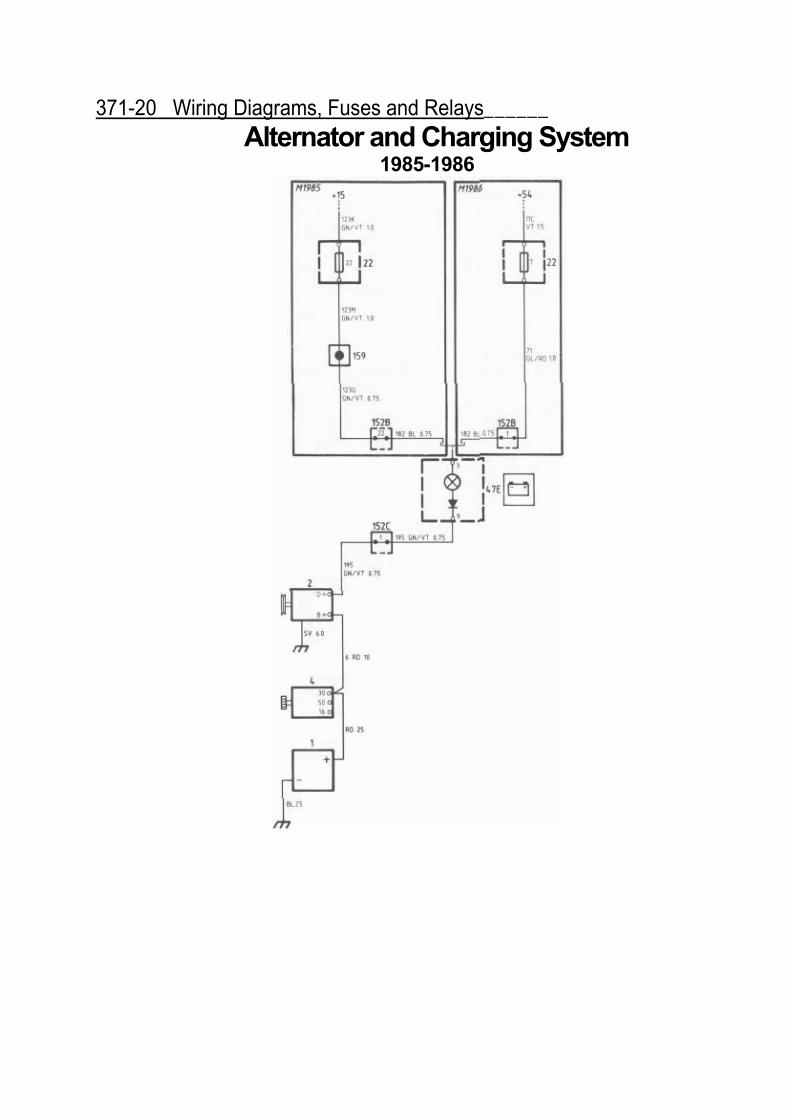
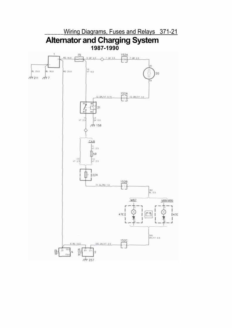
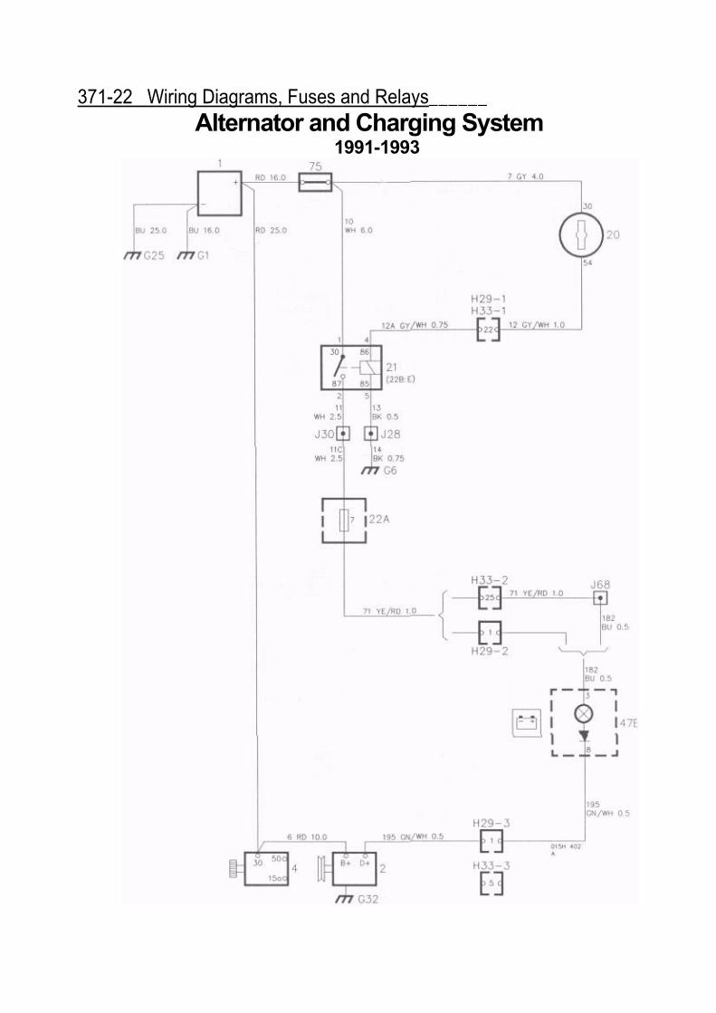
Wiring Diagrams, Fuses and Relays 371-19Alternator andCharging System
Operation
The alternator supplies the electrical componentsand recharges the battery. The alternator is notfused. Voltage regulation is controlled internally by aregulator. The alternator circuit includes a warninglamp in the instrument cluster. If the lamp burns out,the alternator will not charge the battery properly.See 853 Dashboard and Consoles and 351 Lightingfor information on changing the lamp.
See 321 Alternator and Charging System foralternator and charging system repair informationand additional fault tracing.
CAUTION
• Do not disconnect the battery or any wirewhen the engine is running. Do not reverse thepolarity of the battery. Do not ground anyalternator terminals. This will damage thealternator.• Always disconnect the negative (-) batterycable before removing the alternator. Unfusedbattery voltage is always present at the rear ofthe alternator.• Always disconnect the negative {-} batterycable and all wires to the alternator beforedoing any electric (arc) welding to the car.
Fault Tracing1. Inspect the V-belts and make sure they are
tight. Test for a fully charged battery asdescribed in 311 Battery.
2. Check for faulty connections and broken wires.3. If no visible faults can be found, test the
alternator output using an alternator load tester.Alternator output specification• Bosch type 80 A . 54 Amps @ 1900 rpm
NOTE
If A load tester is not available, an output testcan be done by running the engine at 2000 rpmand turning on all electrical loads such as fans,lights and heated window. Voltage at the batteryshould be approximately 12 volts or higher.
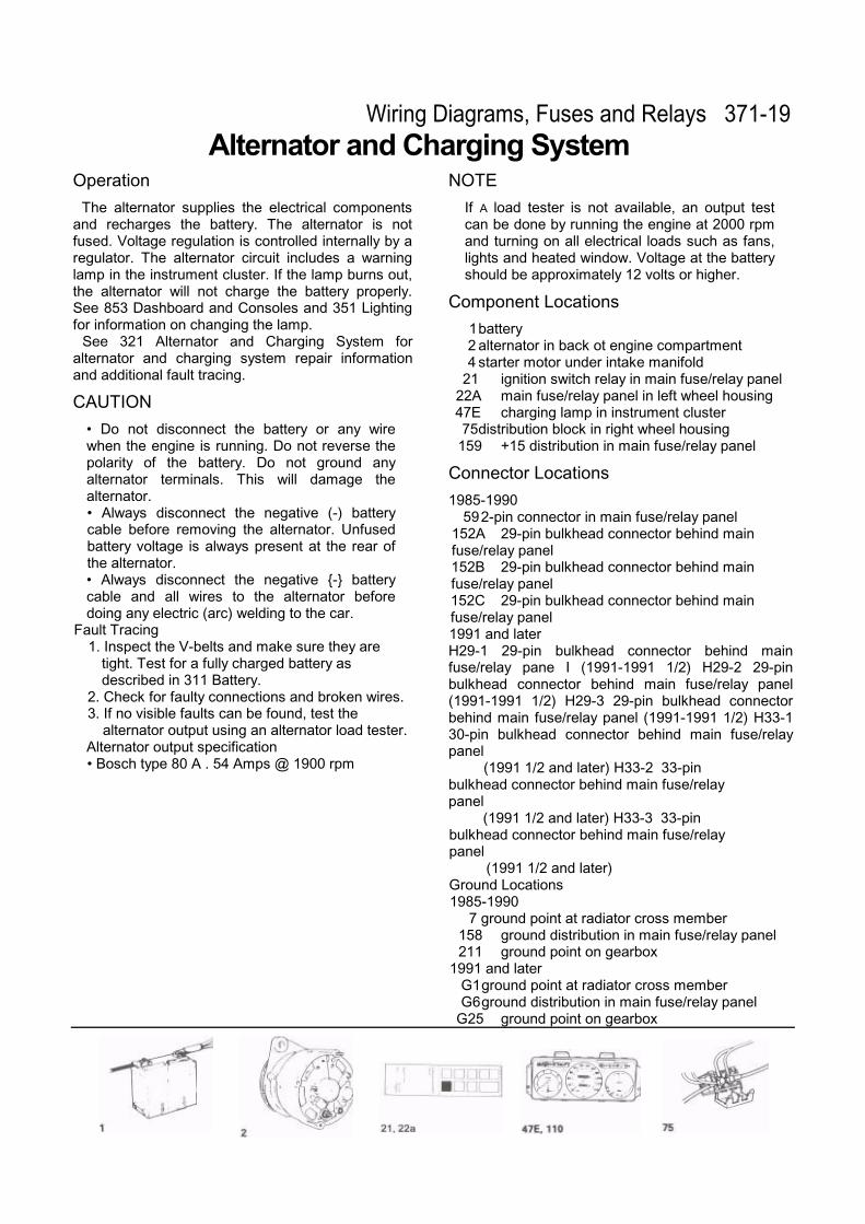
Component Locations
1battery2 alternator in back ot engine compartment4 starter motor under intake manifold
21 ignition switch relay in main fuse/relay panel22A main fuse/relay panel in left wheel housing47E charging lamp in instrument cluster75distribution block in right wheel housing
159 +15 distribution in main fuse/relay panel
Connector Locations
1985-1990592-pin connector in main fuse/relay panel