60
Copyright reserved Please turn over ELECTRICAL TECHNOLOGY GUIDELINES FOR PRACTICAL ASSESSMENT TASKS 2012 These guidelines consist of 60 pages.
Copyright reserved Please turn over
ELECTRICAL TECHNOLOGY
GUIDELINES FOR PRACTICAL ASSESSMENT TASKS
2012
These guidelines consist of 60 pages.
Electrical Technology 2 DBE/PAT 2012 NSC
Copyright reserved Please turn over
TABLE OF CONTENTS
SECTION A (Teacher's guidelines) 3 1. The structure of the PAT 3 2. Administration of the PAT 4 3. Assessment and moderation of the PAT 4 3.1 Assessment 4 3.2 Moderation 6 SECTION B (The learner task) 7 Design and Make Project 10 SECTION C (Simulations) 18 Declaration by learner 59 Working mark sheet (A working Excel file is available from the national co-ordinator) 60
Electrical Technology 3 DBE/PAT 2012 NSC
Copyright reserved Please turn over
SECTION A (Teacher's Guide) 1. The structure of the PAT Practical Assessment Tasks are designed to develop and demonstrate a learner's ability to integrate a variety of skills in order to solve a problem. The PAT also makes use of a technological process to inform the learner that steps need to be followed to derive a solution for the problem at hand. The 2012 PAT has three scenarios and four simulations in each of the following fields: • Electrical • Electronics • Digital Electronics The Practical Assessment Task consists of four simulations and a practical project. The teacher may choose any scenario for the practical project and use a combination of the simulations available. If teachers have a better circuit, they are welcome to use that for the practical circuit. The teacher has to apply assessment on an ongoing basis at the same time that the learner is developing the required hand skills. Once an option has been chosen, four simulations should be completed by the learners, in addition to the manufacturing of a practical project. The PAT incorporates all the skills the learner has developed from Grade 10, 11 and 12. The PAT ensures that all the different skills will be acquired by learners on completion of LO 4, that is, electrical, analogue and digital electronics as well as the correct use of tools and instruments. A complete PAT will consist of the following: • PAT file with all the evidence of simulations, design and prototyping. • Practical project with:
o Enclosure The file must include a design. The enclosure and the design must match. No cardboard boxes will be are allowed while plastic and metal
enclosures will be deemed acceptable. The enclosure should be accessible for scrutiny inside while lids that
are secured with screws will be preferred. o Circuit board
The file should include the PCB design. Mounted inside the enclosure in such a manner that it can be
removed. Switches, potentiometers, connectors and other items must be
mounted. Wiring must be neat and bound Wiring must be long enough to allow for the PCB to be removed and
inspected with ease o Logo and Name
The file should contain the logo and name design. Logo and name must be prominent on the enclosure

Electrical Technology 4 DBE/PAT 2012 NSC
Copyright reserved Please turn over
The PAT will have a financial impact on the school's budget and school management teams should make ample provision to accommodate this particular expense. PAT components and other items must be acquired timeously for use by the learners at the start of each term.
2. Administration of the PAT Teachers must ensure that learners complete the simulations required for each term. The project should be started in January in order to ensure its completion by August. In instances where formal assessments take place, the teacher has to assume the responsibility therefore. The PAT should be completed during the first three terms and must be ready at the start of PAT moderation. Teachers must make copies of the relevant simulations and hand it to learners at the beginning of each term. The PAT must not be allowed to leave the classroom and must be kept in a safe place at all times when learners are not working on it. The weightings of the PAT must be adhered to and teachers are not allowed to change weightings for the different sections.
3. Assessment and moderation of the PAT The Practical Assessment Task for Grade 12 will be externally set and moderated, but internally assessed. All formal assessment will be done by the teacher. The PAT must be moderated by:
• The Head of Department (HOD): It is the responsibility of the HOD to ensure that the teacher is progressing with the PAT from the start of the school year, that is day one.
• Provincial Moderator: Provincial moderator/s will moderate the final PAT during provincial moderation at the end of the third term and will effect changes on the mark sheets as deemed necessary.
3.1 Assessment
Frequent developmental feedback is required to guide and support learners in order to ensure that learners understand what is expected of them.
Both formal and informal assessment should be conducted taking the different tasks that constitute the PAT, into account. The learners should be allowed to conduct Informal assessment themselves, by a peer group or by the teacher. Formal assessment must always remain the responsibility of the teacher and must be recorded for progression purposes.
Teachers should ensure that assessment closely correlates with the assessment rubric and that the marks awarded must comply with the level descriptor in that rubric. If it is found that a discrepancy exists during moderation, teachers will have to re-assess 100% of the tasks that were found to be assessed inaccurately.
Once the rubric has been completed by the teacher, assessment will be deemed to be complete. No re-assessment will be done once the rubrics have been filled in and captured by the teacher. Learners must ensure that the work is done to the standard required before the teacher finally assesses the PAT during each stage of completion.

Electrical Technology 5 DBE/PAT 2012 NSC
Copyright reserved Please turn over
In cases where learners do not submit portions of the PAT, zero marks will be awarded to those portions. Learners that fail to produce a complete PAT by the time moderation starts will receive zero for all sections not completed. Copies of supporting correspondence regarding this issue should be included in the portfolio.
Provincial departments are responsible for setting up set up moderation timetables and consequently PATs should be completed in time for moderation.
The assessment plan for the PAT is as follows:
Time Frame
Activity Responsibility
January– March 2012
Simulation 1 and 2
Teacher – Copy and hand out simulations Learners – Complete simulations Teacher – Assess simulations HOD – Check if tasks have been completed and marked by the teacher before the holiday.
January 2012 PAT Project – Procurement
Teacher – Obtain quotations for PAT projects Principal – Approve PAT procurement for PAT projects Teacher – Ensure that PAT projects are ordered and delivered. HOD – Checks up on teacher to see if the process is being adhered to.
February 2012
PAT Project – Learners commence with project.
Teacher – Ensure that there is secure storage for PAT projects. Teacher – Hands out and takes in PAT projects Teacher – include practical sessions for learners to complete PAT project every week Learners – Commence with completion of the PAT project HOD – Check in on teacher to ensure that practical workshop sessions take place on a weekly basis
April–June 2012
Moderation of Simulation 1 and 2
District Subject Facilitator/Subject Specialist will visit the school and moderate Simulation 1 and 2. 10% of learners are re-marked and moderated.
April–June 2012
Simulation 3 and 4
Teacher – Copy and hand out simulations Learners – Complete simulations Teacher – Assess simulations HOD – Check if tasks have been completed and marked by the teacher before the holiday.
April–June 2012
PAT project – Learners continue with project
Teacher – Ensure that there is secure storage for PAT projects. Teacher – Hands out and takes in PAT projects Teacher – include practical sessions for learners to complete PAT project every week Learners – Continue with completion of the PAT project HOD – Check in on teacher to ensure that practical workshop sessions take place on a weekly basis
July holiday 2012
PAT intervention
Learners that are behind on PAT are required to complete the project during this holiday.
July–August 2012
Moderation of Simulation 3 and 4
District Subject Facilitator/Subject Specialist will visit the school and moderate Simulation 3 and 4. Different learners from the previous term. 10% of learners are re-marked and moderated.
July–August 2012
PAT project – completion
Teacher – Ensure that there is secure storage for PAT projects. Teacher – Hands out and takes in PAT projects Teacher – Completes the PAT project with learners and compiles the PAT File. Learners – Complete the PAT project and file. HOD – Check to see that 100% of PAT files and project are completed and assessed
September–October 2012
PAT moderation
PAT projects are moderated by subject facilitators/subject specialists from the province and learners are available to demonstrate skills. 10% of learners are moderated at random.
Electrical Technology 6 DBE/PAT 2012 NSC
Copyright reserved Please turn over
3.2 Moderation During moderation of the PAT, the portfolio and the project will be presented to the moderator. Moderation of each term's simulations can start as early as the following term, that is Simulation 1 and 2 can be moderated as soon as the second term starts. The project, however, will only be moderated upon completion. The moderation process is as follows: • During moderation learners are randomly selected to demonstrate the different PAT
simulations. All four simulations will be moderated. • Learners being moderated will have access to their completed simulations during
moderation and may refer to the simulations they completed earlier in the year. • Learners may not ask assistance from other learners during moderation. • All projects must be on display for the moderator. • The moderator will select at random no less than two projects (not simulations), of
which learners will have to come and explain how the project was manufactured. • Where required, the moderator should be able to call on the learner to come and
explain the function, principles of operation and also request the learner to exhibit the skills acquired through the simulations for moderation purposes.
• Upon completion the moderator will, if needed, adjust the marks of the group up or downwards, depending on the decision reached as a result of moderation.
• Normal examination protocols for appeals will be adhered to if a dispute arises from adjustments made.
Electrical Technology 7 DBE/PAT 2012 NSC
Copyright reserved Please turn over
Department of Education Grade 12 National Senior Certificate 2012
Practical Assessment Task – Electrical Technology SECTION B (The learner task)
Time Allowed: 1st–3rd term 2012
Learner Name: Examination Number: School: Instructions to the learner:
This practical assessment task counts 25% of your final promotion mark. All work produced by you must be your own effort. Group work and co-operative
work is not allowed. The Practical Assessment Task is completed over three terms. The PAT consists of 4 simulations and a practical project. Calculations should be clear and include units. Calculations should be rounded off
to TWO digits. SI units should be used. Circuit diagrams can be hand-drawn or drawn on CAD. No photocopies or scanned
files are allowed. Photos are allowed and can be in colour or greyscale. Scanned photos and
photocopies are allowed. You are allowed to use recycled components. You are allowed to use a kit. This document must be placed inside the learner portfolio.
Evidence of Moderation:
(NOTE: When the Learner Evidence (LE) selected has been moderated at school level, the table will contain evidence of moderation. Provincial Moderators will sign the provincial moderation and only sign if re-moderation is needed.)
Moderation Signature
Date Signature
Date
School-based
Provincial Moderation
Re-Moderation
PAT Component Maximum Mark Learner Mark
Project Design and Make: Circuit – 80 marks Design and Make: Enclosure – 20 marks
22080 +
=Total
50
Simulation 1 (Term 1) 50 Simulation 2 (Term 1) 50 Simulation 3 (Term 2) 50 Simulation 4 (Term 2) 50
Total 250

Electrical Technology 8 DBE/PAT 2012 NSC
Copyright reserved Please turn over
SECTION B: SCENARIOS Below is one example of a project circuit for each of the possible options learners can choose from. Teachers who have better circuits may use those instead of the following. Teachers should not, however, choose simpler circuits as that would be responsible for lowering standards.
Electrical Project: Backup Light System
Be Careful – mains supply can be lethal! Electronic Project: Two-tone Oscillator
COMPONENT LIST R1 100 kΩ R2 47 kΩ R3 22 kΩ F1 1A fuse Tri 1 Tri 2
TIC 226M TRIAC
Di 1 Di 2
DIAK 30 volts
C1 C2 47 nF (473, 0,047 μF) La1 La2
60 W incandescent lamp
Supply 220 V mains
COMPONENT LIST Rl,R2,R3,R4 33 kΩ R5 22 Ω C1 4,7 uF 16 V C2 22 NF [223 , O.022 uF]C3 100 uF 16 V C4 470 uF 16 V ICI NE555 IC Dl,D2 IN4007 LS Loudspeaker 8 Ω
Electrical Technology 9 DBE/PAT 2012 NSC
Copyright reserved Please turn over
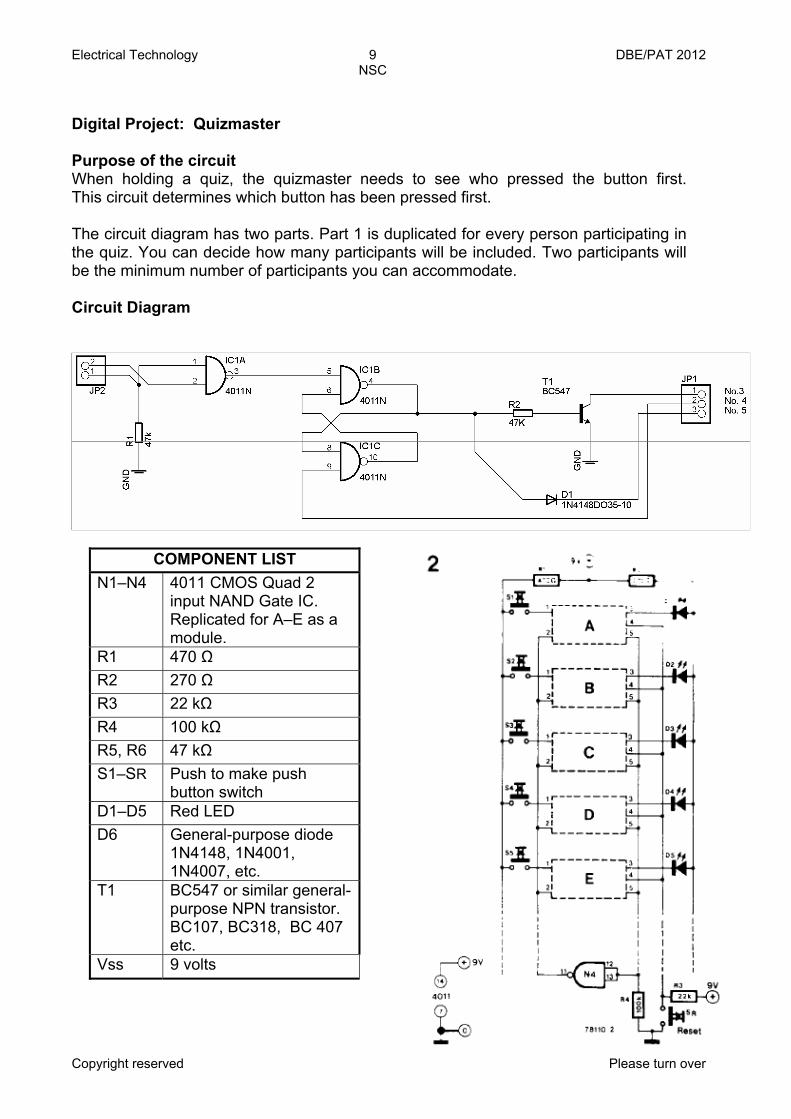
Digital Project: Quizmaster Purpose of the circuit When holding a quiz, the quizmaster needs to see who pressed the button first. This circuit determines which button has been pressed first. The circuit diagram has two parts. Part 1 is duplicated for every person participating in the quiz. You can decide how many participants will be included. Two participants will be the minimum number of participants you can accommodate. Circuit Diagram
COMPONENT LIST
N1–N4 4011 CMOS Quad 2 input NAND Gate IC. Replicated for A–E as a module.
R1 470 Ω R2 270 Ω R3 22 kΩ R4 100 kΩ R5, R6 47 kΩ S1–SR Push to make push
button switch D1–D5 Red LED D6 General-purpose diode
1N4148, 1N4001, 1N4007, etc.
T1 BC547 or similar general- purpose NPN transistor. BC107, BC318, BC 407 etc.
Vss 9 volts
Electrical Technology 10 DBE/PAT 2012 NSC
Copyright reserved Please turn over
Design and Make Project This section is COMPULSORY for all learners. The teacher will choose a circuit for the project, which will be related to the simulations that will be completed.
1. Circuit diagram
Draw a circuit diagram of your project.
Design and Make Project
Time: January–August 2012 Learner Name: School: Examination Number: Title/Type of Project:

Electrical Technology 11 DBE/PAT 2012 NSC
Copyright reserved Please turn over
2. Project: Description of operation
Use the space provided below to provide an overview of how the project functions.
Electrical Technology 12 DBE/PAT 2012 NSC
Copyright reserved Please turn over
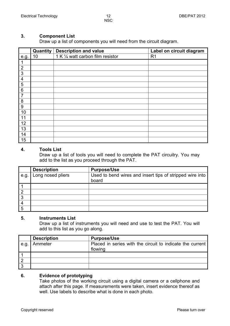
3. Component List
Draw up a list of components you will need from the circuit diagram.
Quantity Description and value Label on circuit diagram e.g. 10 1 K ¼ watt carbon film resistor R1 1 2 3 4 5 6 7 8 9 10 11 12 13 14 15 4. Tools List
Draw up a list of tools you will need to complete the PAT circuitry. You may add to the list as you proceed through the PAT.
Description Purpose/Use e.g. Long nosed pliers Used to bend wires and insert tips of stripped wire into
board 1 2 3 4 5 5. Instruments List
Draw up a list of instruments you will need and use to test the PAT. You will add to this list as you go along.
Description Purpose/Use e.g. Ammeter Placed in series with the circuit to indicate the current
flowing 1 2 3 6. Evidence of prototyping
Take photos of the working circuit using a digital camera or a cellphone and attach after this page. If measurements were taken, insert evidence thereof aswell. Use labels to describe what is done in each photo.
Electrical Technology 13 DBE/PAT 2012 NSC
Copyright reserved Please turn over
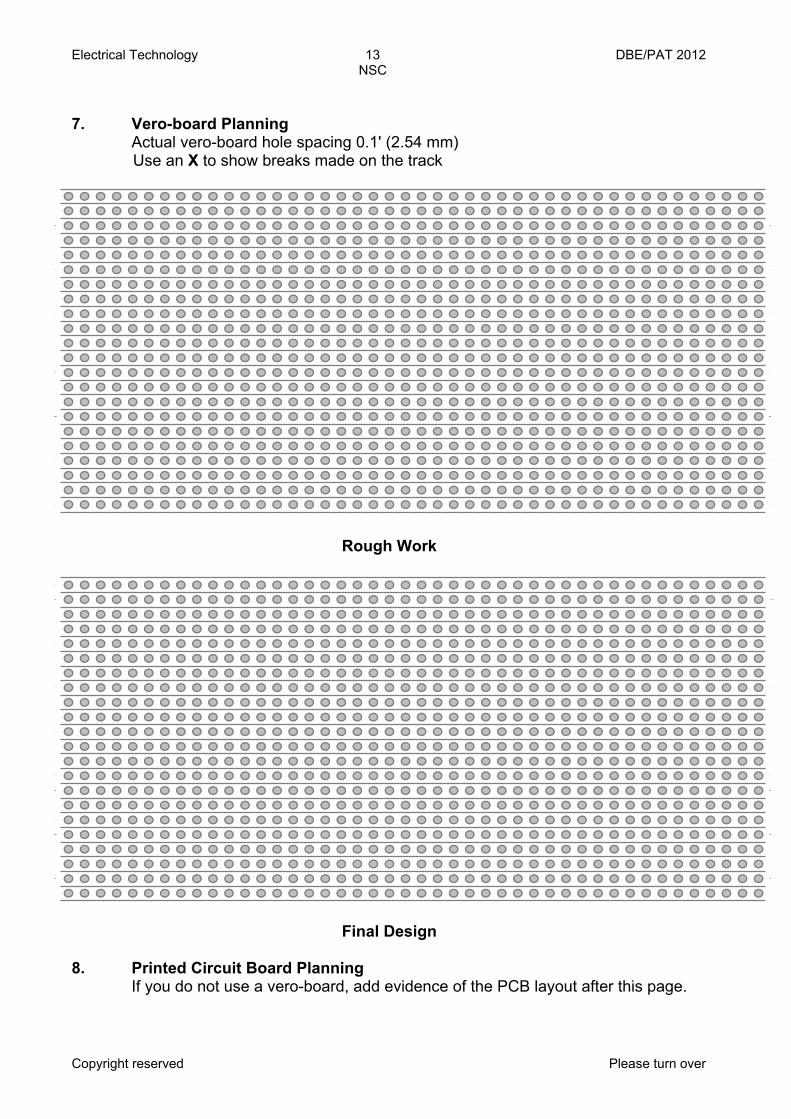
7. Vero-board Planning Actual vero-board hole spacing 0.1' (2.54 mm) Use an X to show breaks made on the track
Rough Work
Final Design 8. Printed Circuit Board Planning If you do not use a vero-board, add evidence of the PCB layout after this page.
1
2
3
4
5
6
7
8
9
1
1
1
1
1
1
1
1
1
1
2
2
2
1
2
3
4
5
6
7
8
9
1
1
1
1
1
1
1
1
1
1
2
2l
2
1
2
3
4
5
6
7
8
9
1
1
1
1
1
1
1
1
1
1
2
2
2
1
2
3
4
5
6
7
8
9
1
1
1
1
1
1
1
1
1
1
2
2l
2
Electrical Technology 14 DBE/PAT 2012 NSC
Copyright reserved Please turn over
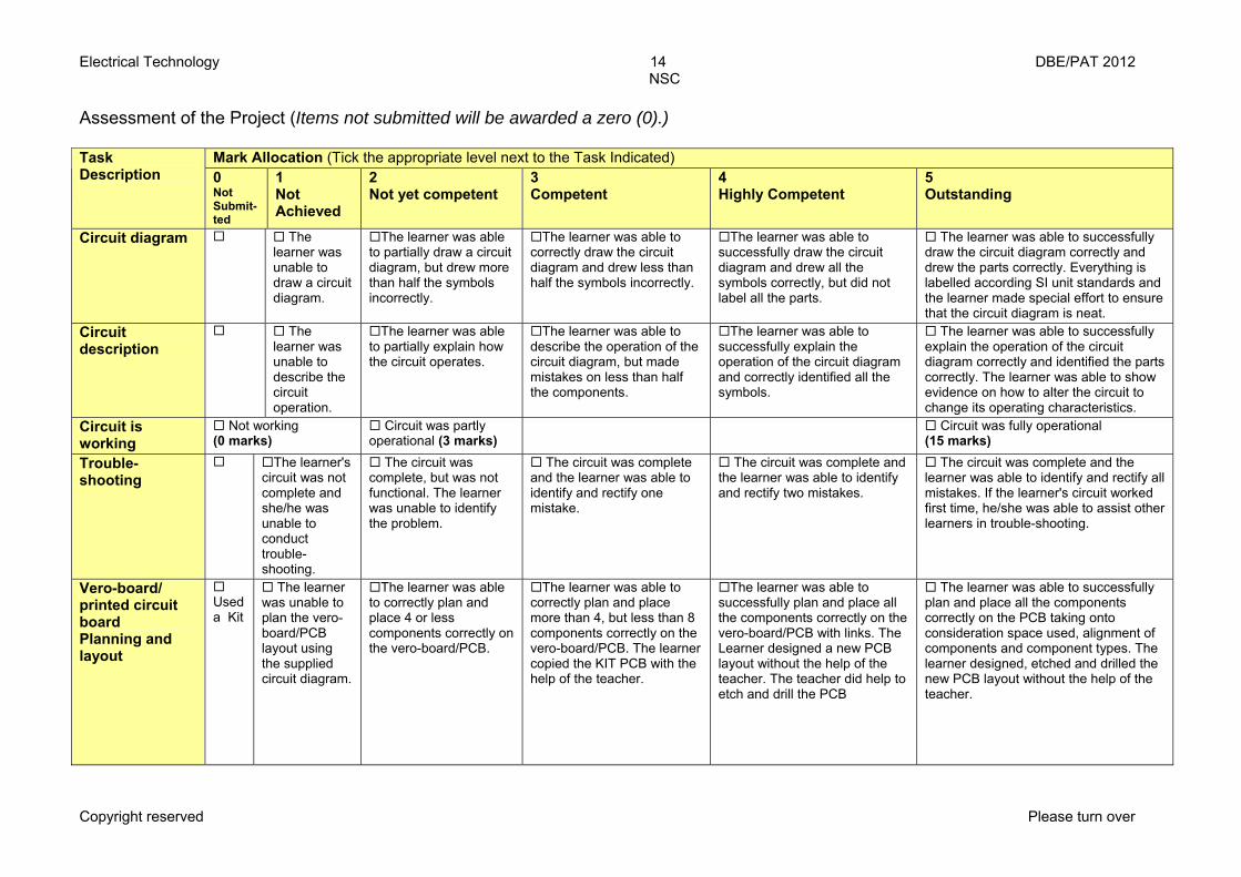
Assessment of the Project (Items not submitted will be awarded a zero (0).)
Mark Allocation (Tick the appropriate level next to the Task Indicated) Task Description
0 Not Submit- ted
1 Not Achieved
2 Not yet competent
3 Competent
4 Highly Competent
5 Outstanding
Circuit diagram The learner was unable to draw a circuit diagram.
The learner was able to partially draw a circuit diagram, but drew more than half the symbols incorrectly.
The learner was able to correctly draw the circuit diagram and drew less than half the symbols incorrectly.
The learner was able to successfully draw the circuit diagram and drew all the symbols correctly, but did not label all the parts.
The learner was able to successfully draw the circuit diagram correctly and drew the parts correctly. Everything is labelled according SI unit standards and the learner made special effort to ensure that the circuit diagram is neat.
Circuit description
The learner was unable to describe the circuit operation.
The learner was able to partially explain how the circuit operates.
The learner was able to describe the operation of the circuit diagram, but made mistakes on less than half the components.
The learner was able to successfully explain the operation of the circuit diagram and correctly identified all the symbols.
The learner was able to successfully explain the operation of the circuit diagram correctly and identified the parts correctly. The learner was able to show evidence on how to alter the circuit to change its operating characteristics.
Circuit is working
Not working (0 marks)
Circuit was partly operational (3 marks)
Circuit was fully operational (15 marks)
Trouble- shooting
The learner's circuit was not complete and she/he was unable to conduct trouble-shooting.
The circuit was complete, but was not functional. The learner was unable to identify the problem.
The circuit was complete and the learner was able to identify and rectify one mistake.
The circuit was complete and the learner was able to identify and rectify two mistakes.
The circuit was complete and the learner was able to identify and rectify all mistakes. If the learner's circuit worked first time, he/she was able to assist other learners in trouble-shooting.
Vero-board/ printed circuit board Planning and layout
Used a Kit
The learner was unable to plan the vero- board/PCB layout using the supplied circuit diagram.
The learner was able to correctly plan and place 4 or less components correctly on the vero-board/PCB.
The learner was able to correctly plan and place more than 4, but less than 8 components correctly on the vero-board/PCB. The learner copied the KIT PCB with the help of the teacher.
The learner was able to successfully plan and place all the components correctly on the vero-board/PCB with links. The Learner designed a new PCB layout without the help of the teacher. The teacher did help to etch and drill the PCB
The learner was able to successfully plan and place all the components correctly on the PCB taking onto consideration space used, alignment of components and component types. The learner designed, etched and drilled the new PCB layout without the help of the teacher.
Electrical Technology 15 DBE/PAT 2012 NSC
Copyright reserved Please turn over
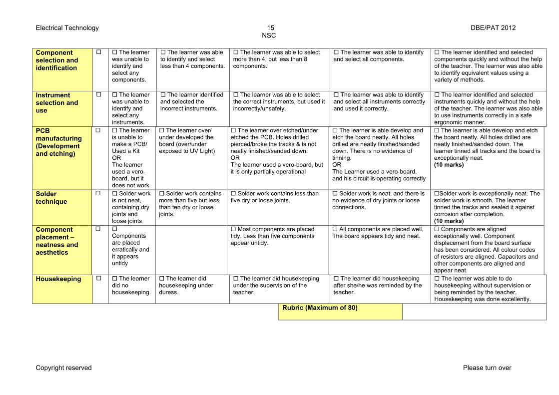
Component selection and identification
The learner was unable to identify and select any components.
The learner was able to identify and select less than 4 components.
The learner was able to select more than 4, but less than 8 components.
The learner was able to identify and select all components.
The learner identified and selected components quickly and without the help of the teacher. The learner was also able to identify equivalent values using a variety of methods.
Instrument selection and use
The learner was unable to identify and select any instruments.
The learner identified and selected the incorrect instruments.
The learner was able to select the correct instruments, but used it incorrectly/unsafely.
The learner was able to identify and select all instruments correctly and used it correctly.
The learner identified and selected instruments quickly and without the help of the teacher. The learner was also able to use instruments correctly in a safe ergonomic manner.
PCB manufacturing (Development and etching)
The learner is unable to make a PCB/ Used a Kit OR The learner used a vero- board, but it does not work
The learner over/ under developed the board (over/under exposed to UV Light)
The learner over etched/under etched the PCB. Holes drilled pierced/broke the tracks & is not neatly finished/sanded down. OR The learner used a vero-board, but it is only partially operational
The learner is able develop and etch the board neatly. All holes drilled are neatly finished/sanded down. There is no evidence of tinning. OR The Learner used a vero-board, and his circuit is operating correctly
The learner is able develop and etch the board neatly. All holes drilled are neatly finished/sanded down. The learner tinned all tracks and the board is exceptionally neat. (10 marks)
Solder technique
Solder work is not neat, containing dry joints and loose joints
Solder work contains more than five but less than ten dry or loose joints.
Solder work contains less than five dry or loose joints.
Solder work is neat, and there is no evidence of dry joints or loose connections.
Solder work is exceptionally neat. The solder work is smooth. The learner tinned the tracks and sealed it against corrosion after completion. (10 marks)
Component placement – neatness and aesthetics
Components are placed erratically and it appears untidy
Most components are placed tidy. Less than five components appear untidy.
All components are placed well. The board appears tidy and neat.
Components are aligned exceptionally well. Component displacement from the board surface has been considered. All colour codes of resistors are aligned. Capacitors and other components are aligned and appear neat.
Housekeeping The learner did no housekeeping.
The learner did housekeeping under duress.
The learner did housekeeping under the supervision of the teacher.
The learner did housekeeping after she/he was reminded by the teacher.
The learner was able to do housekeeping without supervision or being reminded by the teacher. Housekeeping was done excellently.
Rubric (Maximum of 80)
Electrical Technology 16 DBE/PAT 2012 NSC
Copyright reserved Please turn over
9. Enclosure design
Design an enclosure including the layout of the PCB and parts in the enclosure. Make use of colour to actuate your design. You are allowed to use not only hand-drawn designs but also the CAD programme.
1. Attach your design after this page. Show the top, front and side view. 2. Manufacture/Obtain an enclosure according to your design. 3. Take photos of the completed enclosure and attach it after this page. 4. Choose a name for your device. Write down the name of the device
hereunder. _______________________________________________________
5. Design a logo for your device and past it below.
Electrical Technology 17 DBE/PAT 2012 NSC
Copyright reserved Please turn over
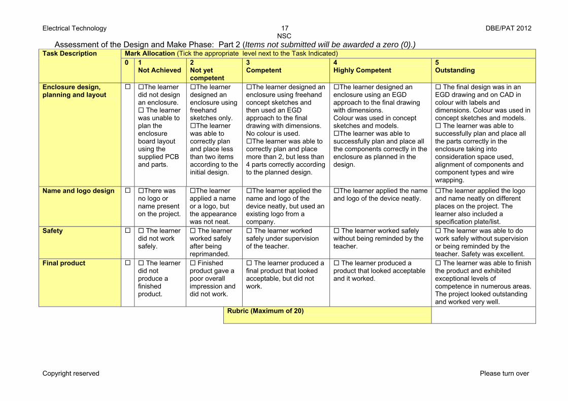
Assessment of the Design and Make Phase: Part 2 (Items not submitted will be awarded a zero (0).) Mark Allocation (Tick the appropriate level next to the Task Indicated) Task Description
0 1 Not Achieved
2 Not yet competent
3 Competent
4 Highly Competent
5 Outstanding
Enclosure design, planning and layout
The learner did not design an enclosure.
The learner was unable to plan the enclosure board layout using the supplied PCB and parts.
The learner designed an enclosure using freehand sketches only.
The learner was able to correctly plan and place less than two items according to the initial design.
The learner designed an enclosure using freehand concept sketches and then used an EGD approach to the final drawing with dimensions. No colour is used.
The learner was able to correctly plan and place more than 2, but less than 4 parts correctly according to the planned design.
The learner designed an enclosure using an EGD approach to the final drawing with dimensions. Colour was used in concept sketches and models.
The learner was able to successfully plan and place all the components correctly in the enclosure as planned in the design.
The final design was in an EGD drawing and on CAD in colour with labels and dimensions. Colour was used in concept sketches and models.
The learner was able to successfully plan and place all the parts correctly in the enclosure taking into consideration space used, alignment of components and component types and wire wrapping.
Name and logo design There was no logo or name present on the project.
The learner applied a name or a logo, but the appearance was not neat.
The learner applied the name and logo of the device neatly, but used an existing logo from a company.
The learner applied the name and logo of the device neatly.
The learner applied the logo and name neatly on different places on the project. The learner also included a specification plate/list.
Safety The learner did not work safely.
The learner worked safely after being reprimanded.
The learner worked safely under supervision of the teacher.
The learner worked safely without being reminded by the teacher.
The learner was able to do work safely without supervision or being reminded by the teacher. Safety was excellent.
Final product The learner did not produce a finished product.
Finished product gave a poor overall impression and did not work.
The learner produced a final product that looked acceptable, but did not work.
The learner produced a product that looked acceptable and it worked.
The learner was able to finish the product and exhibited exceptional levels of competence in numerous areas. The project looked outstanding and worked very well.
Rubric (Maximum of 20)
Electrical Technology 18 DBE/PAT 2012 NSC
Copyright reserved Please turn over
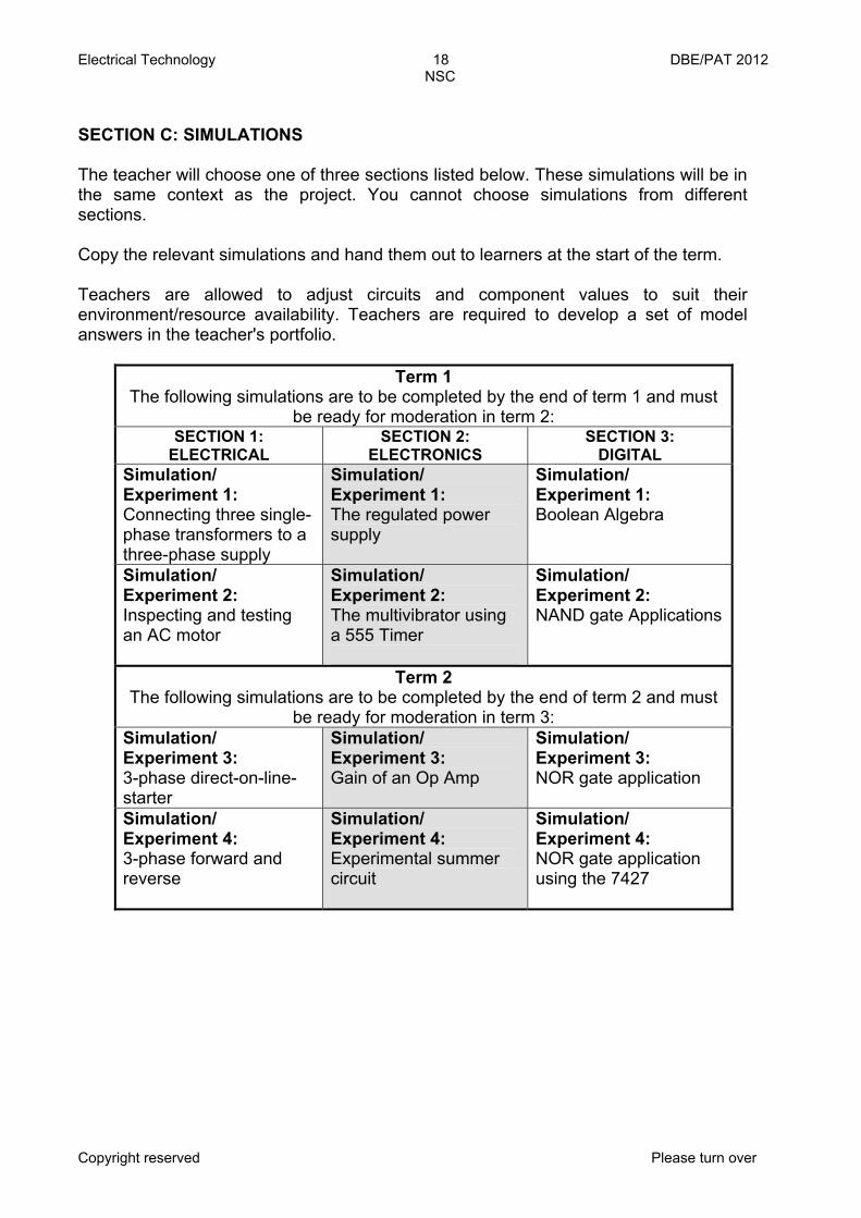
SECTION C: SIMULATIONS The teacher will choose one of three sections listed below. These simulations will be in the same context as the project. You cannot choose simulations from different sections. Copy the relevant simulations and hand them out to learners at the start of the term. Teachers are allowed to adjust circuits and component values to suit their environment/resource availability. Teachers are required to develop a set of model answers in the teacher's portfolio.
Term 1
The following simulations are to be completed by the end of term 1 and must be ready for moderation in term 2:
SECTION 1: ELECTRICAL
SECTION 2: ELECTRONICS
SECTION 3: DIGITAL
Simulation/ Experiment 1: Connecting three single- phase transformers to a three-phase supply
Simulation/ Experiment 1: The regulated power supply
Simulation/ Experiment 1: Boolean Algebra
Simulation/ Experiment 2: Inspecting and testing an AC motor
Simulation/ Experiment 2: The multivibrator using a 555 Timer
Simulation/ Experiment 2: NAND gate Applications
Term 2 The following simulations are to be completed by the end of term 2 and must
be ready for moderation in term 3: Simulation/ Experiment 3: 3-phase direct-on-line- starter
Simulation/ Experiment 3: Gain of an Op Amp
Simulation/ Experiment 3: NOR gate application
Simulation/ Experiment 4: 3-phase forward and reverse
Simulation/ Experiment 4: Experimental summer circuit
Simulation/ Experiment 4: NOR gate application using the 7427
Electrical Technology 19 DBE/PAT 2012 NSC
Copyright reserved Please turn over
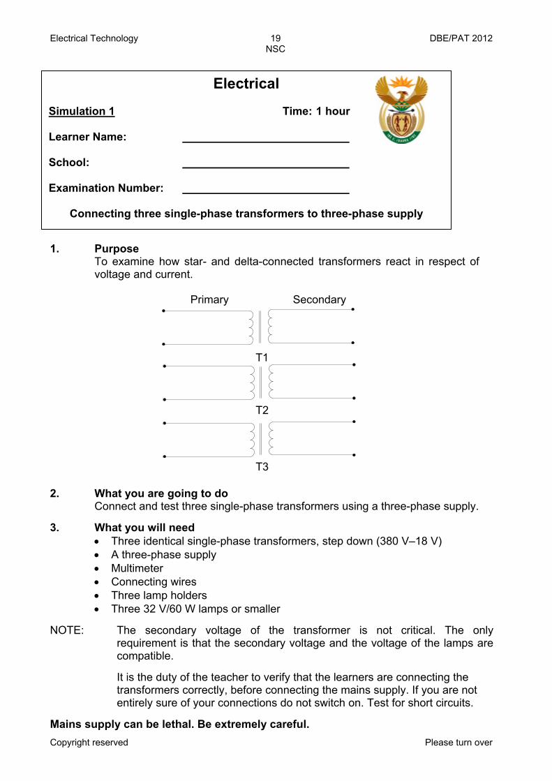
1. Purpose
To examine how star- and delta-connected transformers react in respect of voltage and current.
T2
T1
T3
Primary Secondary
2. What you are going to do
Connect and test three single-phase transformers using a three-phase supply.
3. What you will need
• Three identical single-phase transformers, step down (380 V–18 V) • A three-phase supply • Multimeter • Connecting wires • Three lamp holders • Three 32 V/60 W lamps or smaller
NOTE: The secondary voltage of the transformer is not critical. The only
requirement is that the secondary voltage and the voltage of the lamps are compatible.
It is the duty of the teacher to verify that the learners are connecting the
transformers correctly, before connecting the mains supply. If you are not entirely sure of your connections do not switch on. Test for short circuits.
Mains supply can be lethal. Be extremely careful.
Electrical
Simulation 1 Time: 1 hour Learner Name: School: Examination Number:
Connecting three single-phase transformers to three-phase supply
Electrical Technology 20 DBE/PAT 2012 NSC
Copyright reserved Please turn over
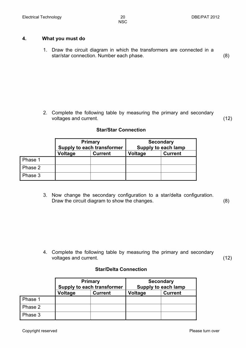
4. What you must do
1. Draw the circuit diagram in which the transformers are connected in a star/star connection. Number each phase.
(8)
2. Complete the following table by measuring the primary and secondary voltages and current.
(12)
Star/Star Connection
Primary
Supply to each transformerSecondary
Supply to each lamp Voltage Current Voltage Current Phase 1 Phase 2 Phase 3
3. Now change the secondary configuration to a star/delta configuration. Draw the circuit diagram to show the changes.
(8)
4. Complete the following table by measuring the primary and secondary voltages and current.
(12)
Star/Delta Connection
Primary
Supply to each transformerSecondary
Supply to each lamp Voltage Current Voltage Current Phase 1 Phase 2 Phase 3
Electrical Technology 21 DBE/PAT 2012 NSC
Copyright reserved Please turn over
5. In your own words describe what happened with the readings between the two different configurations (star/star vs. star/delta). Motivate your answer using a proven mathematical method.
(4)
6. What will happen with the secondary line voltage if you connect the transformers in delta/delta? (Calculate your answer.)
(3)
7. What will the value of the secondary line current be if the transformer is connected in delta/delta? (Calculate your answer.)
(3)
8. Conclusion: Explain in your own words what you have learnt in this experiment.
TOTAL: 50

Electrical Technology 22 DBE/PAT 2012 NSC
Copyright reserved Please turn over
When conducting an inspection and test of an AC motor it is advised to make use of a checklist or report as is shown below. Make use of the list below to conduct an inspection and test on an electrical motor. Your teacher will supply you with a motor to test. Details of the motor under test: (3) Phase: Supply voltage: Pole pares: Speed: Efficiency: Current:
DESCRIPTION VISUAL INSPECTION & READINGS TAKEN (Megger)
MARKS ALLOCATED
Test 1: Continuity of the windings (3 marks) Condition of windings (visual inspection)
A1 – A2
B1 – B2
C1 – C2
Test 2: Insulation resistance between windings (3 marks) A1 – B1
A1 – C1
B1 – C1
Test 3 – Insulation resistance to earth (3 marks) A1 – Earth
B1 – Earth
C1 – Earth
Electrical
Simulation 2 Time: 1 hour Learner Name: School: Examination Number:
Inspecting and Testing the AC Motor

Electrical Technology 23 DBE/PAT 2012 NSC
Copyright reserved Please turn over
Test 4 – Mechanical inspection Note all errors (9 marks)
Condition of rotor and shaft • Key/Key way
• Front bearing
• Back bearing
Condition of motor frame • Condition of termination
box
• Flange/Foot mount
• Front/Back-end shield
• Stator/Field housing
• Mounting bolts and nuts/ Screws
• Condition of cooling fan, fan cover and cooling fins
Test Finding (3 marks)
Is motor operational?
Earth resistance
Insulation resistance
List the recommended repairs that should be affected on the electrical motor under test.
(1)
TOTAL: 25

Electrical Technology 24 DBE/PAT 2012 NSC
Copyright reserved Please turn over
Rubric Simulation 2: Testing an Electric Motor
Mark Allocation (Tick the appropriate level next to the Task Indicated) Task Description
1
Not Achieved 2
Not yet competent
3 Competent
4 Highly Competent
5 Outstanding
Inspection points
The learner did not identify any testing points.
The learner was unable to identify more than two testing points.
The learner was able to identify more than two testing points but could not motivate why these are used.
The learner was able to identify testing points on the motor and inside the motor. The learner was also able to motivate why these points have to be tested.
The learner was able to successfully indicate all testing points in and on the motor. The learner was also to motivate why these points should be tested and was able to list symptoms that indicated certain errors.
Tool selection and use
The learner was unable to identify and select any tools.
The learner identified and selected the incorrect tools.
The learner was able to select the correct tools, but used them incorrectly/ unsafely.
The learner was able to identify and select all tools correctly and used them correctly.
The learner identified and selected tools quickly and without the help of the teacher. The learner was also able to use tools correctly in a safe ergonomic manner.
Troubleshooting The learner's circuit was not complete and she/he was unable to conduct trouble-shooting.
The circuit was complete, but was not functional. The learner was unable to identify the problem.
The circuit was complete and the learner was able to identify and rectify one mistake.
The circuit was complete and the learner was able to identify and rectify two mistakes.
The circuit was complete and the learner was able to identify and rectify all mistakes.
Test continuity and earth resistance
The learner was unable to test continuity and insulation resistance.
The learner was able to test continuity, but not insulation resistance.
The learner was able to test continuity and insulation resistance, but did not know why this was done.
The learner was able to correctly test continuity as well as insulation resistance and had a basic idea of the reason for this.
The learner was able to correctly test continuity as well as insulation resistance and had a solid knowledge of the meters and the reasons for their use.
Housekeeping The learner did no housekeeping.
The learner did housekeeping under duress.
The learner did housekeeping under the supervision of the teacher
The learner did housekeeping after she/he was reminded by the teacher.
The learner was able to do housekeeping without supervision or being reminded by the teacher. Housekeeping was done excellently.
Total of the Rubric
(Maximum of 25)
Written Task (Maximum
of 25)
Total (Maximum of 50)
Electrical Technology 25 DBE/PAT 2012 NSC
Copyright reserved Please turn over
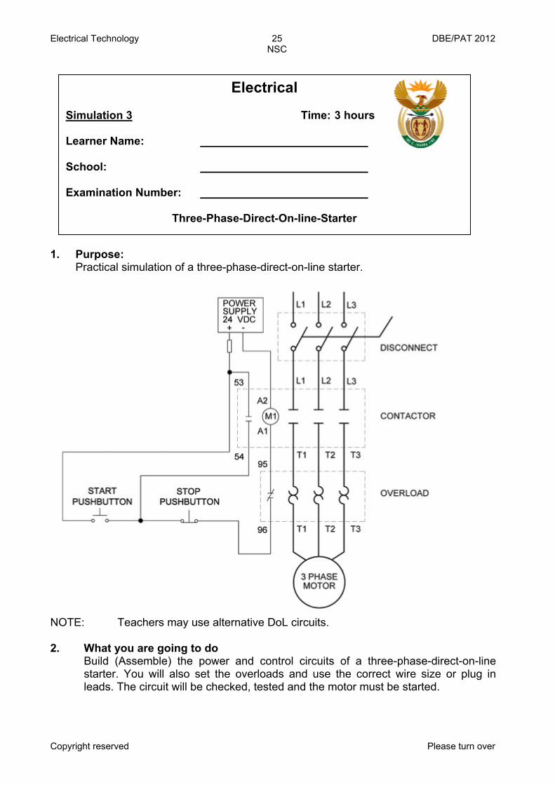
1. Purpose: Practical simulation of a three-phase-direct-on-line starter.
NOTE: Teachers may use alternative DoL circuits. 2. What you are going to do
Build (Assemble) the power and control circuits of a three-phase-direct-on-line starter. You will also set the overloads and use the correct wire size or plug in leads. The circuit will be checked, tested and the motor must be started.
Electrical Simulation 3 Time: 3 hours Learner Name: School: Examination Number:
Three-Phase-Direct-On-line-Starter
Electrical Technology 26 DBE/PAT 2012 NSC
Copyright reserved Please turn over
3. What you will need
1. One, three-phase contactor with auxiliary contacts 2. One three-phase overload relay 3. One stop button, (press-button type) 4. One start button (press-button) 5. One three-phase circuit-breaker 6. One fuse for the control circuit 7. One 380 V delta induction motor (squirrel-cage) 8. Correct wire size or plug in leads 9. Multi-meter or continuity tester 10. Power supply – three-phase
4. What you must do
1. Consult the control and power circuit. 2. Construct/Wire the power and control circuit on the given panel. 3. Connect the motor to the power circuit and set the overload. 4. Now ask the teacher to check the circuits. If they are incorrect repair the
fault. 5. When the circuits are correct switch the supply on and start the motor. 6. Stop the motor and switch the supply off. 7. On completion of the task switch the supply off and strip the circuits.
5. Conclusion:
In which type of industrial application would DoL starters be used? Motivate your answer.
TOTAL: 50 Ref: http://automationnotebook.com/2005_Issue_5/fyi_issue5_2005.html
Electrical Technology 27 DBE/PAT 2012 NSC
Copyright reserved Please turn over
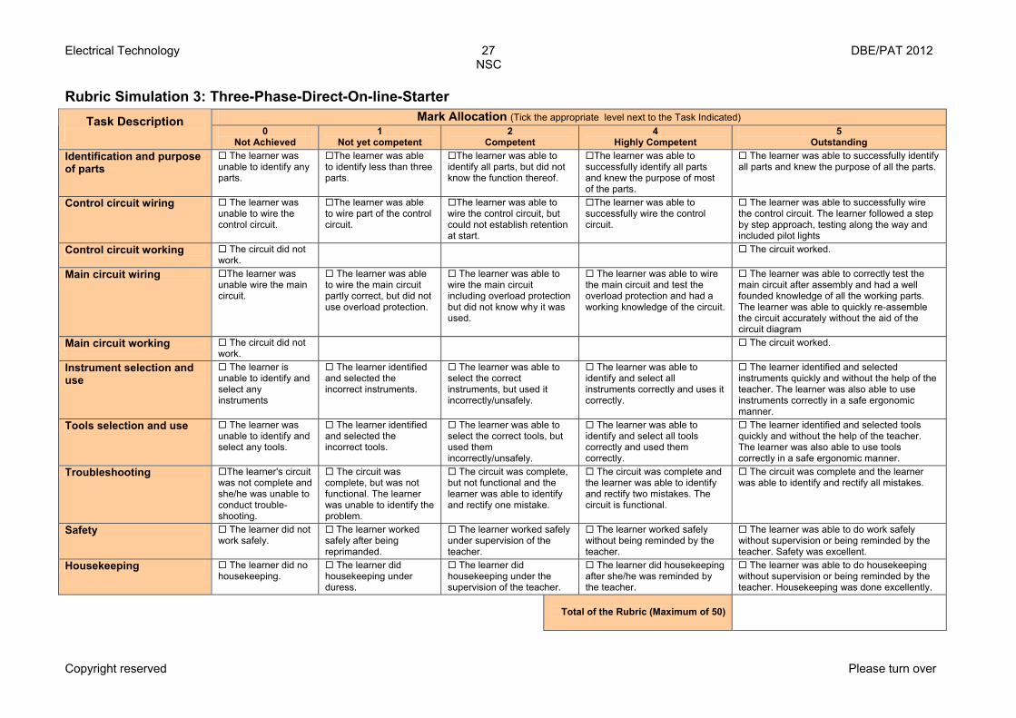
Rubric Simulation 3: Three-Phase-Direct-On-line-Starter
Mark Allocation (Tick the appropriate level next to the Task Indicated) Task Description 0
Not Achieved 1
Not yet competent 2
Competent 4
Highly Competent 5
Outstanding Identification and purpose of parts
The learner was unable to identify any parts.
The learner was able to identify less than three parts.
The learner was able to identify all parts, but did not know the function thereof.
The learner was able to successfully identify all parts and knew the purpose of most of the parts.
The learner was able to successfully identify all parts and knew the purpose of all the parts.
Control circuit wiring The learner was unable to wire the control circuit.
The learner was able to wire part of the control circuit.
The learner was able to wire the control circuit, but could not establish retention at start.
The learner was able to successfully wire the control circuit.
The learner was able to successfully wire the control circuit. The learner followed a step by step approach, testing along the way and included pilot lights
Control circuit working The circuit did not work.
The circuit worked.
Main circuit wiring The learner was unable wire the main circuit.
The learner was able to wire the main circuit partly correct, but did not use overload protection.
The learner was able to wire the main circuit including overload protection but did not know why it was used.
The learner was able to wire the main circuit and test the overload protection and had a working knowledge of the circuit.
The learner was able to correctly test the main circuit after assembly and had a well founded knowledge of all the working parts. The learner was able to quickly re-assemble the circuit accurately without the aid of the circuit diagram
Main circuit working The circuit did not work.
The circuit worked.
Instrument selection and use
The learner is unable to identify and select any instruments
The learner identified and selected the incorrect instruments.
The learner was able to select the correct instruments, but used it incorrectly/unsafely.
The learner was able to identify and select all instruments correctly and uses it correctly.
The learner identified and selected instruments quickly and without the help of the teacher. The learner was also able to use instruments correctly in a safe ergonomic manner.
Tools selection and use The learner was unable to identify and select any tools.
The learner identified and selected the incorrect tools.
The learner was able to select the correct tools, but used them incorrectly/unsafely.
The learner was able to identify and select all tools correctly and used them correctly.
The learner identified and selected tools quickly and without the help of the teacher. The learner was also able to use tools correctly in a safe ergonomic manner.
Troubleshooting The learner's circuit was not complete and she/he was unable to conduct trouble-shooting.
The circuit was complete, but was not functional. The learner was unable to identify the problem.
The circuit was complete, but not functional and the learner was able to identify and rectify one mistake.
The circuit was complete and the learner was able to identify and rectify two mistakes. The circuit is functional.
The circuit was complete and the learner was able to identify and rectify all mistakes.
Safety The learner did not work safely.
The learner worked safely after being reprimanded.
The learner worked safely under supervision of the teacher.
The learner worked safely without being reminded by the teacher.
The learner was able to do work safely without supervision or being reminded by the teacher. Safety was excellent.
Housekeeping The learner did no housekeeping.
The learner did housekeeping under duress.
The learner did housekeeping under the supervision of the teacher.
The learner did housekeeping after she/he was reminded by the teacher.
The learner was able to do housekeeping without supervision or being reminded by the teacher. Housekeeping was done excellently.
Total of the Rubric (Maximum of 50)
Electrical Technology 28 DBE/PAT 2012 NSC
Copyright reserved Please turn over
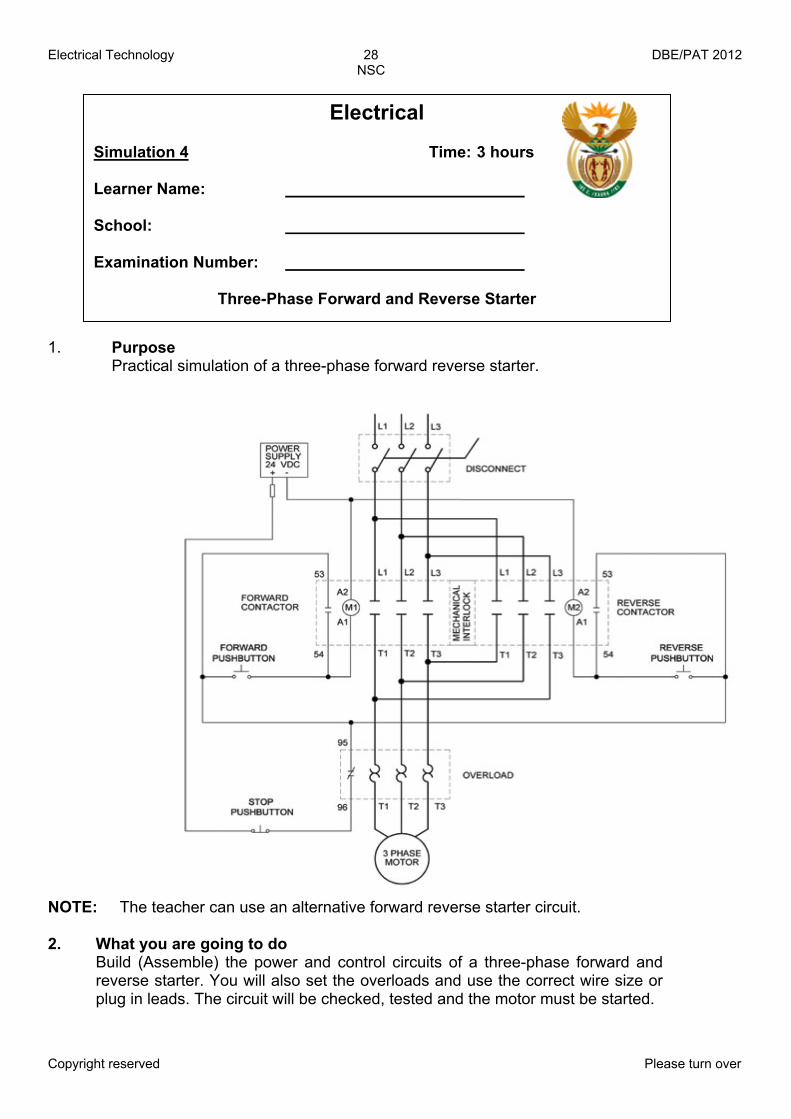
1. Purpose Practical simulation of a three-phase forward reverse starter.
NOTE: The teacher can use an alternative forward reverse starter circuit. 2. What you are going to do Build (Assemble) the power and control circuits of a three-phase forward and reverse starter. You will also set the overloads and use the correct wire size or plug in leads. The circuit will be checked, tested and the motor must be started.
Electrical Simulation 4 Time: 3 hours Learner Name: School: Examination Number:
Three-Phase Forward and Reverse Starter
Electrical Technology 29 DBE/PAT 2012 NSC
Copyright reserved Please turn over
3. What you will need
1. Two, three-phase contactors with auxiliary contacts 2. One timer with normally open and closed contacts 3. Two stops, one for the emergency stop (press button type) 4. One start (press button) 5. One three-phase circuit-breaker 6. One overload relay 7. Two fuses for the control circuit 8. One 380 V delta induction motor (squirrel-cage) 9. Correct wire size or plug in leads 10. Multi-meter or continuity tester 11. Power supply
4. What you must do
1. Consult the control and power circuit. 2. Construct/Wire the power and control circuit on the given panel. 3. Connect the motor to the power circuit and set the overload. 4. Now ask the teacher to check the circuits. If they are incorrect repair the
fault. 5. When the circuits are correct, switch the supply on and start the motor. 6. Stop the motor and switch the supply off. 7. On completion of the task switch the supply off and strip the circuits.
5. Conclusion
Give TWO examples where this circuit can be used effectively.
TOTAL: 10
Ref: http://automationnotebook.com/2005_Issue_5/fyi_issue5_2005.html
Electrical Technology 30 DBE/PAT 2012 NSC
Copyright reserved Please turn over
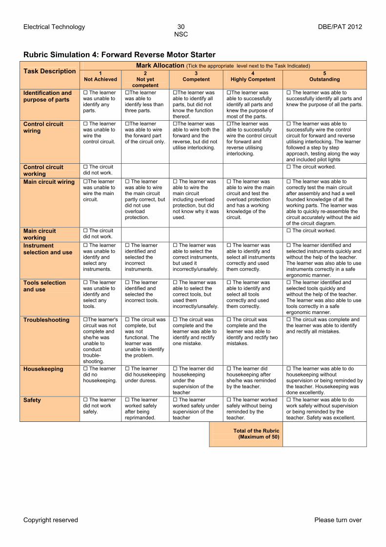
Rubric Simulation 4: Forward Reverse Motor Starter
Mark Allocation (Tick the appropriate level next to the Task Indicated) Task Description
1
Not Achieved 2
Not yet competent
3 Competent
4 Highly Competent
5 Outstanding
Identification and purpose of parts
The learner was unable to identify any parts.
The learner was able to identify less than three parts.
The learner was able to identify all parts, but did not know the function thereof.
The learner was able to successfully identify all parts and knew the purpose of most of the parts.
The learner was able to successfully identify all parts and knew the purpose of all the parts.
Control circuit wiring
The learner was unable to wire the control circuit.
The learner was able to wire the forward part of the circuit only.
The learner was able to wire both the forward and the reverse, but did not utilise interlocking.
The learner was able to successfully wire the control circuit for forward and reverse utilising interlocking.
The learner was able to successfully wire the control circuit for forward and reverse utilising interlocking. The learner followed a step by step approach, testing along the way and included pilot lights
Control circuit working
The circuit did not work.
The circuit worked.
Main circuit wiring The learner was unable to wire the main circuit.
The learner was able to wire the main circuit partly correct, but did not use overload protection.
The learner was able to wire the main circuit including overload protection, but did not know why it was used.
The learner was able to wire the main circuit and test the overload protection and has a working knowledge of the circuit.
The learner was able to correctly test the main circuit after assembly and had a well founded knowledge of all the working parts. The learner was able to quickly re-assemble the circuit accurately without the aid of the circuit diagram.
Main circuit working
The circuit did not work.
The circuit worked.
Instrument selection and use
The learner was unable to identify and select any instruments.
The learner identified and selected the incorrect instruments.
The learner was able to select the correct instruments, but used it incorrectly/unsafely.
The learner was able to identify and select all instruments correctly and used them correctly.
The learner identified and selected instruments quickly and without the help of the teacher. The learner was also able to use instruments correctly in a safe ergonomic manner.
Tools selection and use
The learner was unable to identify and select any tools.
The learner identified and selected the incorrect tools.
The learner was able to select the correct tools, but used them incorrectly/unsafely.
The learner was able to identify and select all tools correctly and used them correctly.
The learner identified and selected tools quickly and without the help of the teacher. The learner was also able to use tools correctly in a safe ergonomic manner.
Troubleshooting The learner's circuit was not complete and she/he was unable to conduct trouble-shooting.
The circuit was complete, but was not functional. The learner was unable to identify the problem.
The circuit was complete and the learner was able to identify and rectify one mistake.
The circuit was complete and the learner was able to identify and rectify two mistakes.
The circuit was complete and the learner was able to identify and rectify all mistakes.
Housekeeping The learner did no housekeeping.
The learner did housekeeping under duress.
The learner did housekeeping under the supervision of the teacher
The learner did housekeeping after she/he was reminded by the teacher.
The learner was able to do housekeeping without supervision or being reminded by the teacher. Housekeeping was done excellently.
Safety The learner did not work safely.
The learner worked safely after being reprimanded.
The learner worked safely under supervision of the teacher
The learner worked safely without being reminded by the teacher.
The learner was able to do work safely without supervision or being reminded by the teacher. Safety was excellent.
Total of the Rubric
(Maximum of 50)

Electrical Technology 31 DBE/PAT 2012 NSC
Copyright reserved Please turn over
1. 2.
Purpose To show the working of the different stages in a regulated power supply and to demonstrate the waveforms present in each stage. Circuit diagram The circuit diagram showed below forms the basis of the design of your power supply.
NOTE: This circuit above uses a 13 volt Zener diode, D2, which provides the voltage regulation. Approximately 0,6–0,7 volts are dropped across the transistor's b-e junction, leaving a higher current 12,3 volt output supply. This circuit can supply loads of up to 500 mA. 3. What you are going to do Build (Assemble) the power supply shown above using the values supplied. If these specific value components are not available, make use of the nearest available value. (As close to the original as possible.)
Electronic Simulation 1 Time: 3 hours Learner Name: School: Examination Number:
The Regulated Power Supply
Electrical Technology 32 DBE/PAT 2012 NSC
Copyright reserved Please turn over
4. What you will need
1. A transformer 240 V–18 V (remember nearest possible value) 2. Components 3. Multimeter 4. Oscilloscope 5. Connecting wires 6. Breadboard 7. Tools
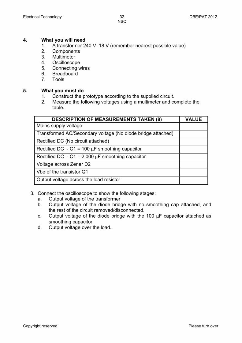
5. What you must do
1. Construct the prototype according to the supplied circuit. 2. Measure the following voltages using a multimeter and complete the
table.
DESCRIPTION OF MEASUREMENTS TAKEN (8) VALUE
Mains supply voltage Transformed AC/Secondary voltage (No diode bridge attached) Rectified DC (No circuit attached) Rectified DC - C1 = 100 μF smoothing capacitor Rectified DC - C1 = 2 000 μF smoothing capacitor Voltage across Zener D2 Vbe of the transistor Q1 Output voltage across the load resistor
3. Connect the oscilloscope to show the following stages:
a. Output voltage of the transformer b. Output voltage of the diode bridge with no smoothing cap attached, and
the rest of the circuit removed/disconnected. c. Output voltage of the diode bridge with the 100 μF capacitor attached as
smoothing capacitor d. Output voltage over the load.

Electrical Technology 33 DBE/PAT 2012 NSC
Copyright reserved Please turn over
Oscillogram of output voltage of the transformer (3 marks)
Oscillogram of output voltage of the diode bridge with no smoothing cap attached, and the rest of the circuit removed/disconnected (3 marks)
Oscillogram of output voltage of the
diode bridge with the 100 μF capacitor attached as smoothing capacitor
(3 marks)
Oscillogram of output voltage over the load (3 marks)
6. Conclusion
The oscillograms indicate how an alternating current/voltage can be changed to a direct current/voltage using a regulated power supply circuit.
TOTAL: 10
Electrical Technology 34 DBE/PAT 2012 NSC
Copyright reserved Please turn over
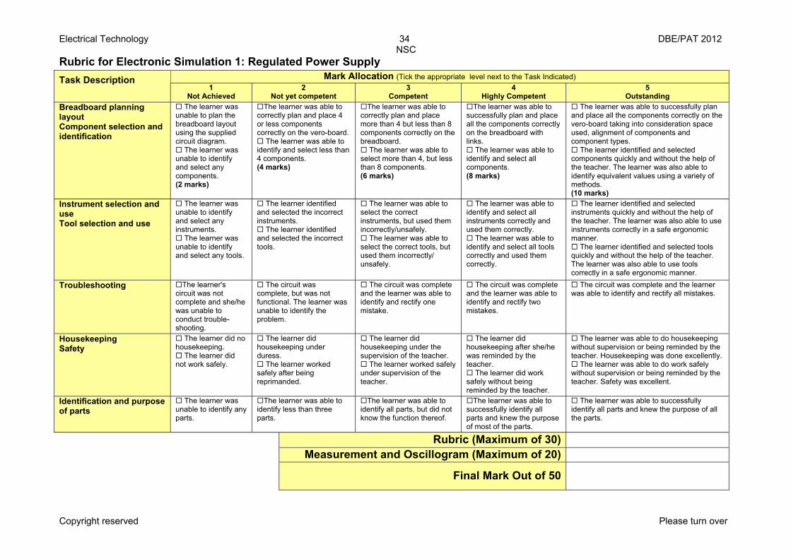
Rubric for Electronic Simulation 1: Regulated Power Supply
Mark Allocation (Tick the appropriate level next to the Task Indicated) Task Description 1
Not Achieved 2
Not yet competent 3
Competent 4
Highly Competent 5
Outstanding Breadboard planning layout Component selection and identification
The learner was unable to plan the breadboard layout using the supplied circuit diagram.
The learner was unable to identify and select any components. (2 marks)
The learner was able to correctly plan and place 4 or less components correctly on the vero-board.
The learner was able to identify and select less than 4 components. (4 marks)
The learner was able to correctly plan and place more than 4 but less than 8 components correctly on the breadboard.
The learner was able to select more than 4, but less than 8 components. (6 marks)
The learner was able to successfully plan and place all the components correctly on the breadboard with links.
The learner was able to identify and select all components. (8 marks)
The learner was able to successfully plan and place all the components correctly on the vero-board taking into consideration space used, alignment of components and component types.
The learner identified and selected components quickly and without the help of the teacher. The learner was also able to identify equivalent values using a variety of methods. (10 marks)
Instrument selection and use Tool selection and use
The learner was unable to identify and select any instruments.
The learner was unable to identify and select any tools.
The learner identified and selected the incorrect instruments.
The learner identified and selected the incorrect tools.
The learner was able to select the correct instruments, but used them incorrectly/unsafely.
The learner was able to select the correct tools, but used them incorrectly/ unsafely.
The learner was able to identify and select all instruments correctly and used them correctly.
The learner was able to identify and select all tools correctly and used them correctly.
The learner identified and selected instruments quickly and without the help of the teacher. The learner was also able to use instruments correctly in a safe ergonomic manner.
The learner identified and selected tools quickly and without the help of the teacher. The learner was also able to use tools correctly in a safe ergonomic manner.
Troubleshooting The learner's circuit was not complete and she/he was unable to conduct trouble-shooting.
The circuit was complete, but was not functional. The learner was unable to identify the problem.
The circuit was complete and the learner was able to identify and rectify one mistake.
The circuit was complete and the learner was able to identify and rectify two mistakes.
The circuit was complete and the learner was able to identify and rectify all mistakes.
Housekeeping Safety
The learner did no housekeeping.
The learner did not work safely.
The learner did housekeeping under duress.
The learner worked safely after being reprimanded.
The learner did housekeeping under the supervision of the teacher.
The learner worked safely under supervision of the teacher.
The learner did housekeeping after she/he was reminded by the teacher.
The learner did work safely without being reminded by the teacher.
The learner was able to do housekeeping without supervision or being reminded by the teacher. Housekeeping was done excellently.
The learner was able to do work safely without supervision or being reminded by the teacher. Safety was excellent.
Identification and purpose of parts
The learner was unable to identify any parts.
The learner was able to identify less than three parts.
The learner was able to identify all parts, but did not know the function thereof.
The learner was able to successfully identify all parts and knew the purpose of most of the parts.
The learner was able to successfully identify all parts and knew the purpose of all the parts.
Rubric (Maximum of 30) Measurement and Oscillogram (Maximum of 20)
Final Mark Out of 50
Electrical Technology 35 DBE/PAT 2012 NSC
Copyright reserved Please turn over
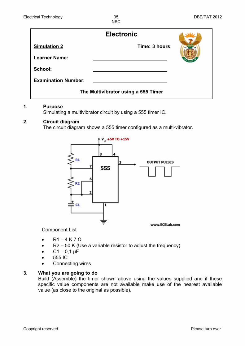
1. 2.
Purpose Simulating a multivibrator circuit by using a 555 timer IC. Circuit diagram The circuit diagram shows a 555 timer configured as a multi-vibrator.
Component List
• R1 – 4 K 7 Ω • R2 – 50 K (Use a variable resistor to adjust the frequency) • C1 – 0,1 μF • 555 IC • Connecting wires
3. What you are going to do Build (Assemble) the timer shown above using the values supplied and if these specific value components are not available make use of the nearest available value (as close to the original as possible).
Electronic Simulation 2 Time: 3 hours Learner Name: School: Examination Number:
The Multivibrator using a 555 Timer
Electrical Technology 36 DBE/PAT 2012 NSC
Copyright reserved Please turn over
4. What you will need
1. A power supply (set between 5–15 volts) 2. Components 3. Multi-meter 4. Oscilloscope 5. Connecting wires 6. Breadboard 7. Tools
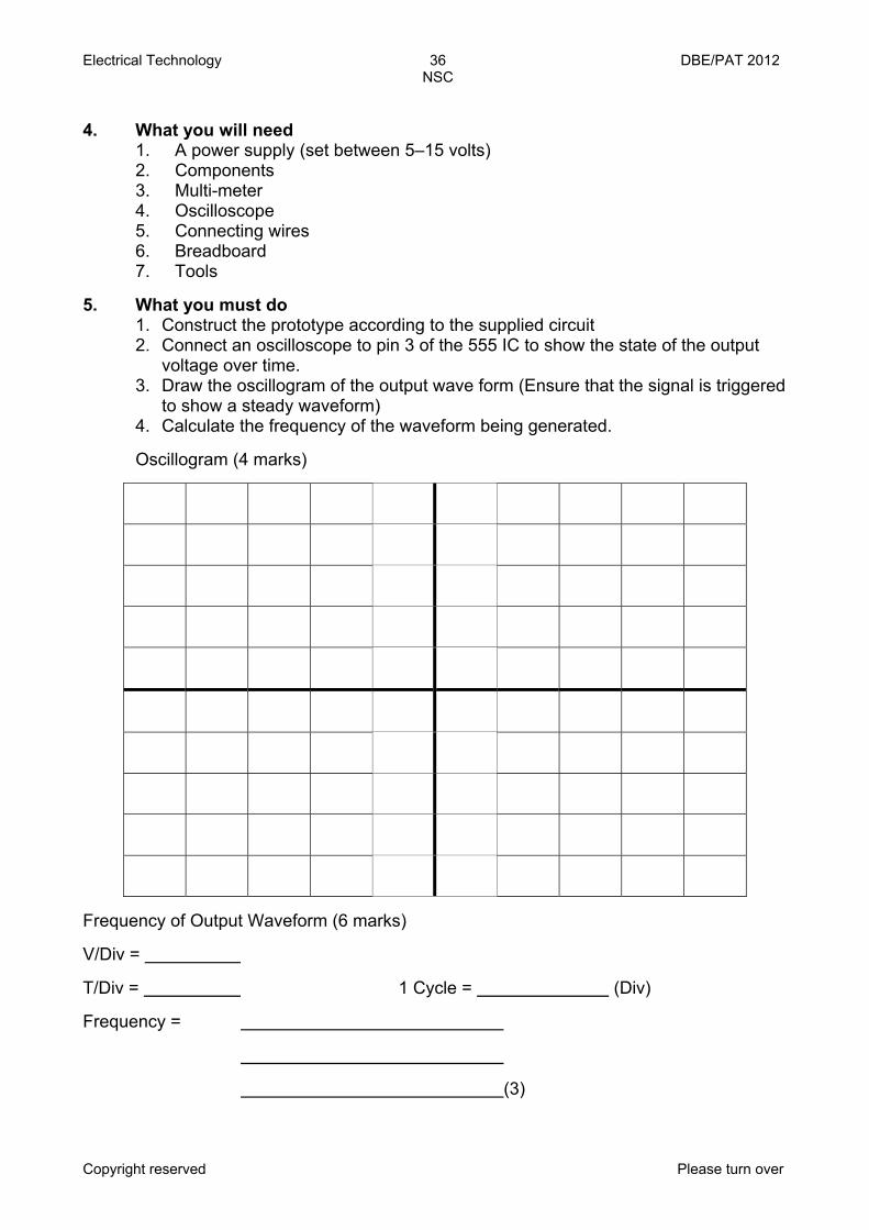
5. What you must do
1. Construct the prototype according to the supplied circuit 2. Connect an oscilloscope to pin 3 of the 555 IC to show the state of the output voltage over time. 3. Draw the oscillogram of the output wave form (Ensure that the signal is triggered to show a steady waveform) 4. Calculate the frequency of the waveform being generated.
Oscillogram (4 marks)
Frequency of Output Waveform (6 marks) V/Div = T/Div = 1 Cycle = (Div) Frequency = (3)

Electrical Technology 37 DBE/PAT 2012 NSC
Copyright reserved Please turn over
6. Conclusion
The astable multivibrator circuit is a type of oscillating circuit that produces a square wave output that can be used as a clock pulse for other circuits.
TOTAL: 10
Electrical Technology 38 DBE/PAT 2012 NSC
Copyright reserved Please turn over
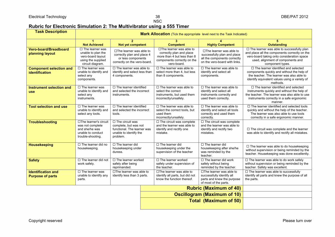
Rubric for Electronic Simulation 2: The Multivibrator using a 555 Timer Task Description
Mark Allocation (Tick the appropriate level next to the Task Indicated)
1 Not Achieved
2 Not yet competent
3 Competent
4 Highly Competent
5 Outstanding
Vero-board/Breadboard planning layout
The learner was unable to plan the vero-board layout using the supplied
circuit diagram.
The learner was able to correctly plan and place 4
or less components correctly on the vero-board.
The learner was able to correctly plan and place
more than 4 but less than 8 components correctly on the
vero-board.
The learner was able to successfully plan and place all the components correctly on the vero-board with links.
The learner was able to successfully plan and place all the components correctly on the vero-board taking onto consideration space
used, alignment of components and component types.
Component selection and identification
The learner was unable to identify and select any components.
The learner was able to identify and select less than 4 components.
The learner was able to select more than 4, but less than 8 components.
The learner was able to identify and select all components.
The learner identified and selected components quickly and without the help of the teacher. The learner was also able to
identify equivalent values using a variety of methods.
Instrument selection and use
The learner was unable to identify and select any instruments.
The learner identified and selected the incorrect instruments.
The learner was able to select the correct instruments, but used them incorrectly/unsafely.
The learner was able to identify and select all instruments correctly and used them correctly.
The learner identified and selected instruments quickly and without the help of
the teacher. The learner was also able to use instruments correctly in a safe ergonomic
manner. Tool selection and use The learner was
unable to identify and select any tools.
The learner identified and selected the incorrect tools.
The learner was able to select the correct tools, but used them incorrectly/unsafely.
The learner was able to identify and select all tools correctly and used them correctly.
The learner identified and selected tools quickly and without the help of the teacher.
The learner was also able to use tools correctly in a safe ergonomic manner.
Troubleshooting The learner's circuit was not complete and she/he was unable to conduct trouble-shooting.
The circuit was complete, but was not functional. The learner was unable to identify the problem.
The circuit was complete and the learner was able to identify and rectify one mistake.
The circuit was complete and the learner was able to identify and rectify two mistakes.
The circuit was complete and the learner was able to identify and rectify all mistakes.
Housekeeping The learner did no housekeeping.
The learner did housekeeping under duress.
The learner did housekeeping under the supervision of the teacher
The learner did housekeeping after she/he was reminded by the teacher.
The learner was able to do housekeeping without supervision or being reminded by the teacher. Housekeeping was done excellently.
Safety The learner did not work safely.
The learner worked safely after being reprimanded.
The learner worked safely under supervision of the teacher.
The learner did work safely without being reminded by the teacher.
The learner was able to do work safely without supervision or being reminded by the teacher. Safety was excellent.
Identification and Purpose of parts
The learner was unable to identify any parts.
The learner was able to identify less than 3 parts.
The learner was able to identify all parts, but did not know the function thereof.
The learner was able to successfully identify all parts and knew the purpose of most of the parts.
The learner was able to successfully identify all parts and knew the purpose of all the parts.
Rubric (Maximum of 40) Oscillogram (Maximum of 10)
Total (Maximum of 50)
Electrical Technology 39 DBE/PAT 2012 NSC
Copyright reserved Please turn over
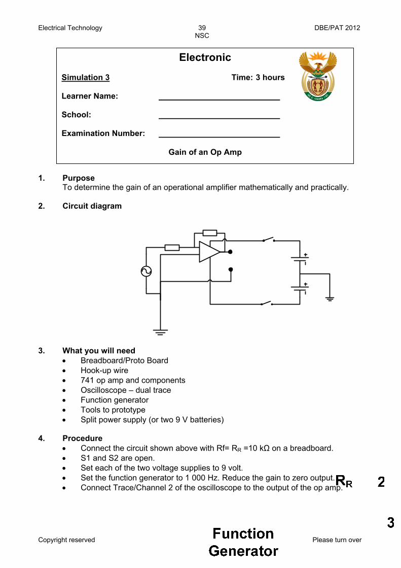
1. Purpose To determine the gain of an operational amplifier mathematically and practically.
2. Circuit diagram
3. What you will need • Breadboard/Proto Board • Hook-up wire • 741 op amp and components • Oscilloscope – dual trace • Function generator • Tools to prototype • Split power supply (or two 9 V batteries)
4. Procedure
• Connect the circuit shown above with Rf= RR =10 kΩ on a breadboard. • S1 and S2 are open. • Set each of the two voltage supplies to 9 volt. • Set the function generator to 1 000 Hz. Reduce the gain to zero output. • Connect Trace/Channel 2 of the oscilloscope to the output of the op amp.
Electronic Simulation 3 Time: 3 hours Learner Name: School: Examination Number:
Gain of an Op Amp
Electrical Technology 40 DBE/PAT 2012 NSC
Copyright reserved Please turn over
• Externally trigger/sync the oscilloscope with the output of the function generator.
• Connect the input wave from the function generator to trace/channel 1 of the oscilloscope.
• Close S1 and S2 applying power to the circuit. • Slowly increase the output of the function generator to just below the point
where the output signal is being distorted. (Look at both the input and the output waveforms and compare the shape to see if the output is being distorted.)
• With the oscilloscope measure and record the output voltage Vout from the amplifier (output pin 6) (peak to peak value).
• With the oscilloscope measure and record the input voltage Vin to the amplifier (output of the signal generator) (peak to peak value).
• Calculate the gain of the amplifier and record it in the table. • Compare the input and output waveforms and determine whether or not they
are in our out of phase with each other (0º or 180º). • Reduce the output of the function generator to zero. • Repeat the experiment, each time replacing RR with the values shown in the
table1.
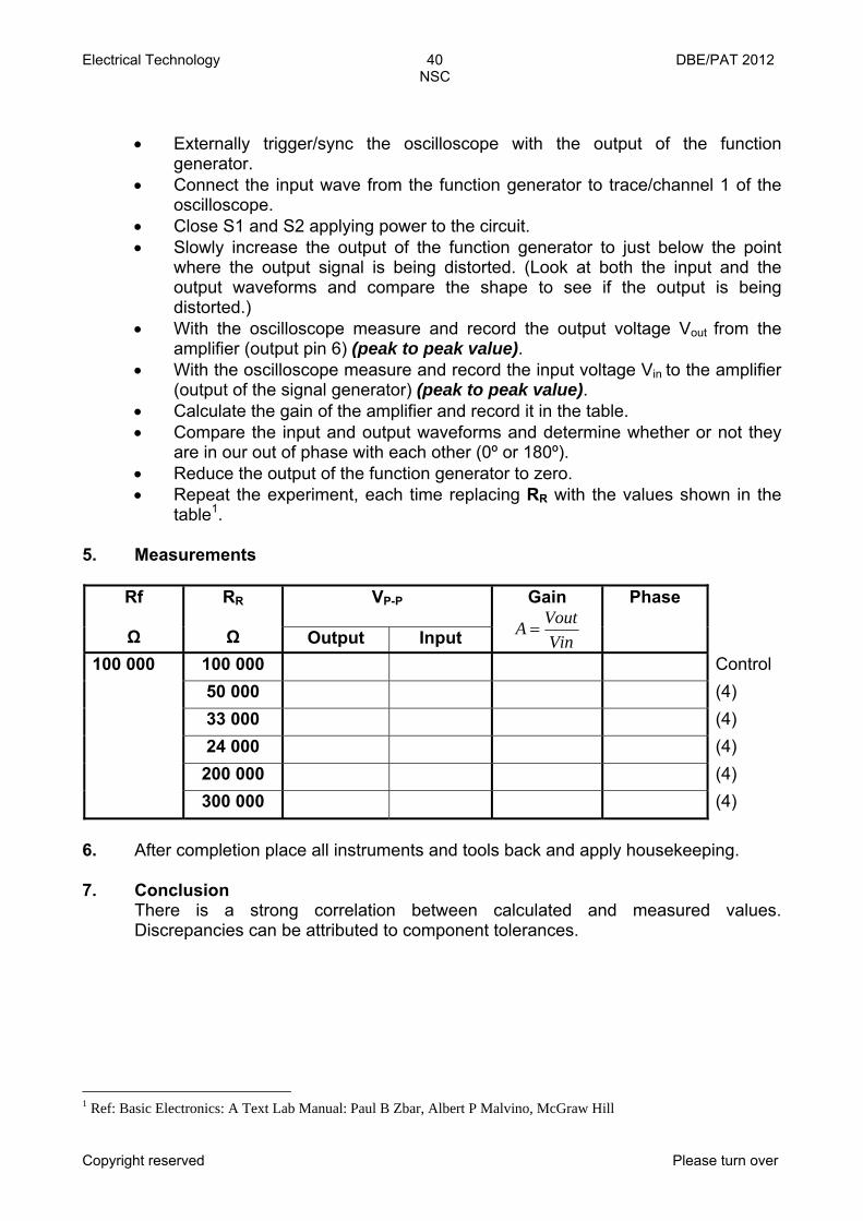
5. Measurements
VP-P
Rf Ω
RR Ω Output Input
Gain
VinVoutA =
Phase
100 000 Control50 000 (4) 33 000 (4) 24 000 (4) 200 000 (4)
100 000
300 000 (4)
6. After completion place all instruments and tools back and apply housekeeping. 7. Conclusion
There is a strong correlation between calculated and measured values. Discrepancies can be attributed to component tolerances.
1 Ref: Basic Electronics: A Text Lab Manual: Paul B Zbar, Albert P Malvino, McGraw Hill
Electrical Technology 41 DBE/PAT 2012 NSC
Copyright reserved Please turn over
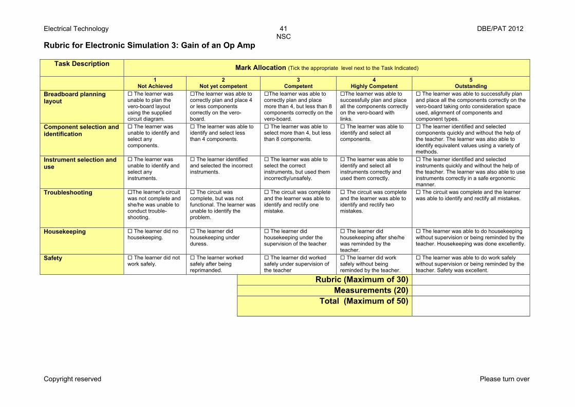
Rubric for Electronic Simulation 3: Gain of an Op Amp
Task Description Mark Allocation (Tick the appropriate level next to the Task Indicated)
1 Not Achieved
2 Not yet competent
3 Competent
4 Highly Competent
5 Outstanding
Breadboard planning layout
The learner was unable to plan the vero-board layout using the supplied circuit diagram.
The learner was able to correctly plan and place 4 or less components correctly on the vero-board.
The learner was able to correctly plan and place more than 4, but less than 8 components correctly on the vero-board.
The learner was able to successfully plan and place all the components correctly on the vero-board with links.
The learner was able to successfully plan and place all the components correctly on the vero-board taking onto consideration space used, alignment of components and component types.
Component selection and identification
The learner was unable to identify and select any components.
The learner was able to identify and select less than 4 components.
The learner was able to select more than 4, but less than 8 components.
The learner was able to identify and select all components.
The learner identified and selected components quickly and without the help of the teacher. The learner was also able to identify equivalent values using a variety of methods.
Instrument selection and use
The learner was unable to identify and select any instruments.
The learner identified and selected the incorrect instruments.
The learner was able to select the correct instruments, but used them incorrectly/unsafely.
The learner was able to identify and select all instruments correctly and used them correctly.
The learner identified and selected instruments quickly and without the help of the teacher. The learner was also able to use instruments correctly in a safe ergonomic manner.
Troubleshooting The learner's circuit was not complete and she/he was unable to conduct trouble-shooting.
The circuit was complete, but was not functional. The learner was unable to identify the problem.
The circuit was complete and the learner was able to identify and rectify one mistake.
The circuit was complete and the learner was able to identify and rectify two mistakes.
The circuit was complete and the learner was able to identify and rectify all mistakes.
Housekeeping The learner did no housekeeping.
The learner did housekeeping under duress.
The learner did housekeeping under the supervision of the teacher
The learner did housekeeping after she/he was reminded by the teacher.
The learner was able to do housekeeping without supervision or being reminded by the teacher. Housekeeping was done excellently.
Safety The learner did not work safely.
The learner worked safely after being reprimanded.
The learner did worked safely under supervision of the teacher
The learner did work safely without being reminded by the teacher.
The learner was able to do work safely without supervision or being reminded by the teacher. Safety was excellent.
Rubric (Maximum of 30) Measurements (20)
Total (Maximum of 50)
Electrical Technology 42 DBE/PAT 2012 NSC
Copyright reserved Please turn over
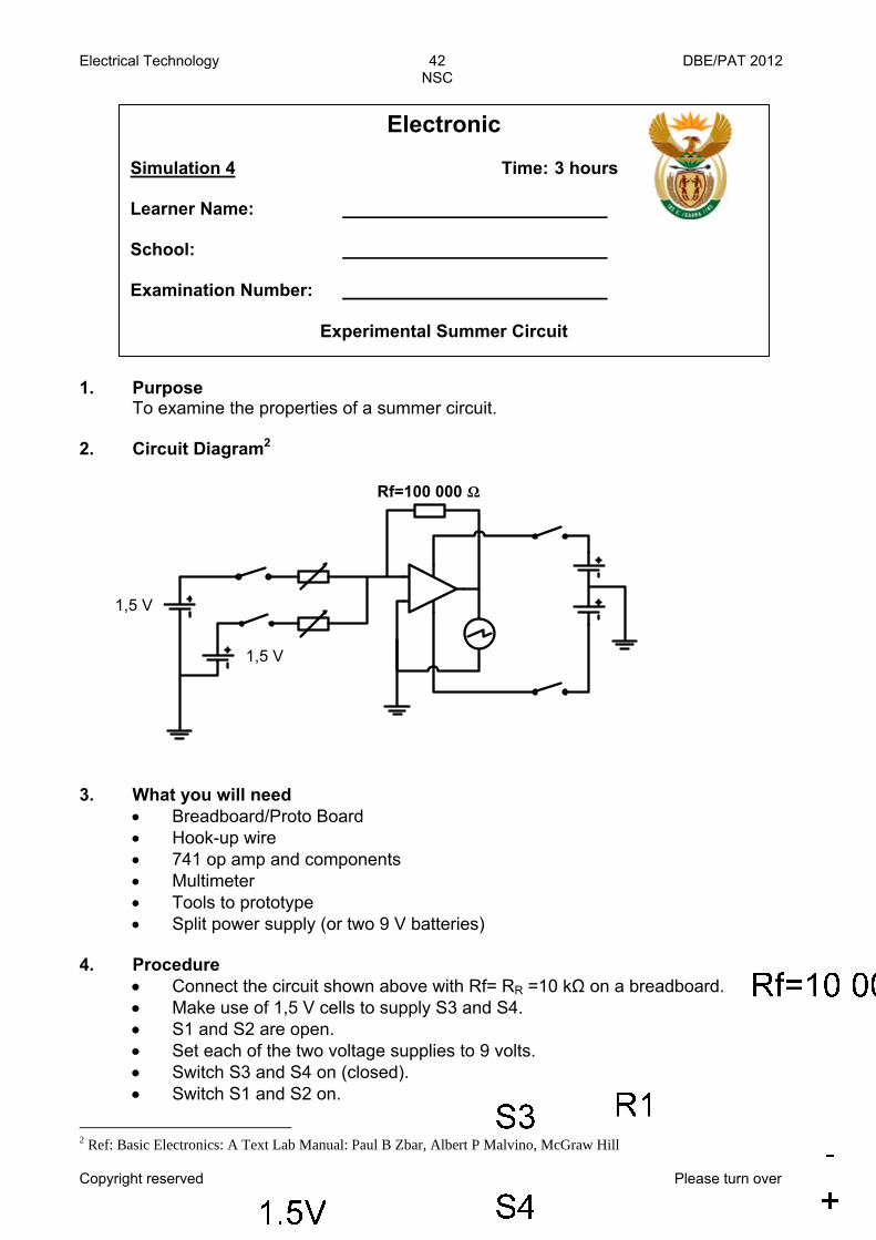
1. Purpose To examine the properties of a summer circuit. 2. Circuit Diagram2
3. What you will need
• Breadboard/Proto Board • Hook-up wire • 741 op amp and components • Multimeter • Tools to prototype • Split power supply (or two 9 V batteries)
4. Procedure
• Connect the circuit shown above with Rf= RR =10 kΩ on a breadboard. • Make use of 1,5 V cells to supply S3 and S4. • S1 and S2 are open. • Set each of the two voltage supplies to 9 volts. • Switch S3 and S4 on (closed). • Switch S1 and S2 on.
2 Ref: Basic Electronics: A Text Lab Manual: Paul B Zbar, Albert P Malvino, McGraw Hill
Electronic Simulation 4 Time: 3 hours Learner Name: School: Examination Number:
Experimental Summer Circuit
Rf=100 000 Ω
1,5 V
1,5 V
Electrical Technology 43 DBE/PAT 2012 NSC
Copyright reserved Please turn over
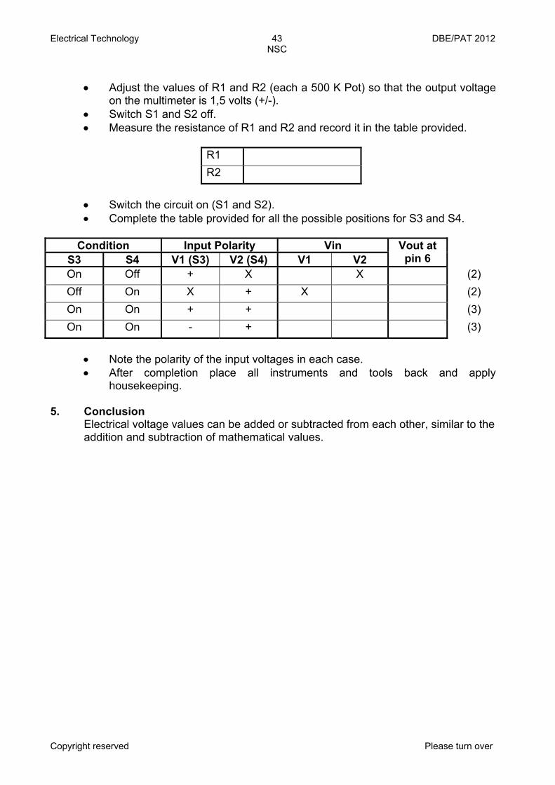
• Adjust the values of R1 and R2 (each a 500 K Pot) so that the output voltage
on the multimeter is 1,5 volts (+/-). • Switch S1 and S2 off. • Measure the resistance of R1 and R2 and record it in the table provided.
R1 R2
• Switch the circuit on (S1 and S2). • Complete the table provided for all the possible positions for S3 and S4.
Condition Input Polarity Vin
S3 S4 V1 (S3) V2 (S4) V1 V2 Vout at pin 6
On Off + X X (2) Off On X + X (2) On On + + (3) On On - + (3)
• Note the polarity of the input voltages in each case. • After completion place all instruments and tools back and apply
housekeeping. 5. Conclusion
Electrical voltage values can be added or subtracted from each other, similar to the addition and subtraction of mathematical values.
Electrical Technology 44 DBE/PAT 2012 NSC
Copyright reserved Please turn over
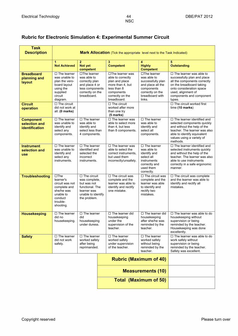
Rubric for Electronic Simulation 4: Experimental Summer Circuit
Task Description
Mark Allocation (Tick the appropriate level next to the Task Indicated)
1 Not Achieved
2 Not yet competent
3 Competent
4 Highly Competent
5 Outstanding
Breadboard planning and layout
The learner was unable to plan the vero- board layout using the supplied circuit diagram.
The learner was able to correctly plan and place 4 or less components correctly on the breadboard.
The learner was able to correctly plan and place more than 4, but less than 8 components correctly on the breadboard.
The learner was able to successfully plan and place all the components correctly on the breadboard with links.
The learner was able to successfully plan and place all the components correctly on the breadboard taking onto consideration space used, alignment of components and component types.
Circuit operation
The circuit did not work at all. (0 marks)
The circuit worked after more than one try (5 marks)
The circuit worked first time (10 marks)
Component selection and identification
The learner was unable to identify and select any components.
The learner was able to identify and select less than 4 components.
The learner was able to select more than 4, but less than 8 components.
The learner was able to identify and select all components.
The learner identified and selected components quickly and without the help of the teacher. The learner was also able to identify equivalent values using a variety of methods.
Instrument selection and use
The learner was unable to identify and select any instruments.
The learner identified and selected the incorrect instruments.
The learner was able to select the correct instruments, but used them incorrectly/unsafely.
The learner was able to identify and select all instruments correctly and used them correctly.
The learner identified and selected instruments quickly and without the help of the teacher. The learner was also able to use instruments correctly in a safe ergonomic manner.
Troubleshooting The learner's circuit was not complete and she/he was unable to conduct trouble-shooting.
The circuit was complete, but was not functional. The learner was unable to identify the problem.
The circuit was complete and the learner was able to identify and rectify one mistake.
The circuit was complete and the learner was able to identify and rectify two mistakes.
The circuit was complete and the learner was able to identify and rectify all mistakes.
Housekeeping The learner did no housekeeping.
The learner did housekeeping under duress.
The learner did housekeeping under the supervision of the teacher.
The learner did housekeeping after she/he was reminded by the teacher.
The learner was able to do housekeeping without supervision or being reminded by the teacher. Housekeeping was done excellently.
Safety The learner did not work safely.
The learner worked safely after being reprimanded.
The learner worked safely under supervision of the teacher.
The learner worked safely without being reminded by the teacher.
The learner was able to do work safely without supervision or being reminded by the teacher. Safety was excellent.
Rubric (Maximum of 40)
Measurements (10)
Total (Maximum of 50)

Electrical Technology 45 DBE/PAT 2012 NSC
Copyright reserved Please turn over
1. Purpose To test Boolean Algebra and construct an electronic circuit that simulates an Boolean expression.
In the year 1847, English mathematician George Boole (1815–1864) published, The Mathematical Analysis of Logic. This book showed how using a specific set of logic can help one to wade through piles of data to find the required information. The importance of Boole's work was his approach to logic. By incorporating logic into mathematics, Boole was able to determine what formed the base of Boolean logic or algebra. It was the analogy which algebraic symbols had with those that represented logical forms. This basic analogy gave birth to what is known as the Boolean Logic or Boolean algebra. As we know, the working of computers are based on the binary number
system (1 or 0), where 1 means 'ON' and 0 signifies 'OFF'. These two states are represented by a difference in voltage. During the time when Boole was defining his Boolean logic, Charles Babbage was developing his 'analytical engine' – today's computer. Therefore the Boolean logic has been in use with the ancestor of the digital computer.
In order to work with and construct digital circuits we will first have to assess your knowledge and understanding of Boolean algebra.
2. Determine the Boolean equation for the following logic gate circuit: (7)
Digital Simulation 1 Time: 3 hours Learner Name: School: Examination Number:
Boolean Algebra

Electrical Technology 46 DBE/PAT 2012 NSC
Copyright reserved Please turn over
3. Draw the logic gate circuit for the Boolean Equation ( ) CX A B= + (4) 4. Determine the Boolean equation for the following truth table: (4)
X =
5. Redraw the following circuit by making use of NAND gate combinations: (6)
A B C X 0 0 0 0 0 0 1 1 0 1 0 0 0 1 1 1 1 0 0 0 1 0 1 1 1 1 0 0 1 1 1 0
Electrical Technology 47 DBE/PAT 2012 NSC
Copyright reserved Please turn over
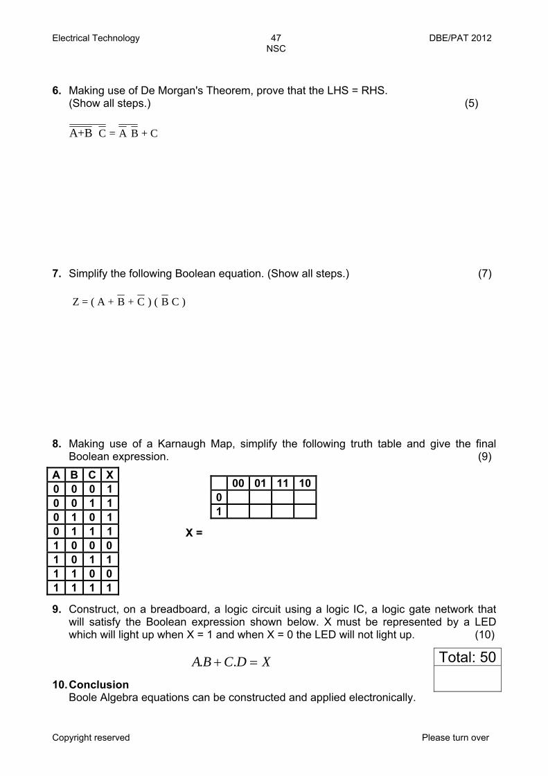
6. Making use of De Morgan's Theorem, prove that the LHS = RHS. (Show all steps.) (5)
C = A B + CA+B 7. Simplify the following Boolean equation. (Show all steps.) (7)
Z = ( A + B + C ) ( B C ) 8. Making use of a Karnaugh Map, simplify the following truth table and give the final Boolean expression. (9)
X =
9. Construct, on a breadboard, a logic circuit using a logic IC, a logic gate network that will satisfy the Boolean expression shown below. X must be represented by a LED which will light up when X = 1 and when X = 0 the LED will not light up. (10)
XDCBA =+ ..
10. Conclusion Boole Algebra equations can be constructed and applied electronically.
A B C X 0 0 0 1 0 0 1 1 0 1 0 1 0 1 1 1 1 0 0 0 1 0 1 1 1 1 0 0 1 1 1 1
00 01 11 100 1
Total: 50
Electrical Technology 48 DBE/PAT 2012 NSC
Copyright reserved Please turn over
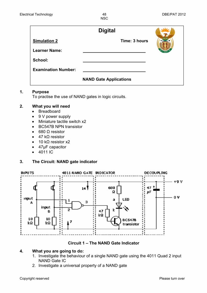
1. Purpose To practise the use of NAND gates in logic circuits. 2. What you will need
• Breadboard • 9 V power supply • Miniature tactile switch x2 • BC547B NPN transistor • 680 Ω resistor • 47 kΩ resistor • 10 kΩ resistor x2 • 47μF capacitor • 4011 IC
3. The Circuit: NAND gate indicator
Circuit 1 – The NAND Gate Indicator 4. What you are going to do:
1. Investigate the behaviour of a single NAND gate using the 4011 Quad 2 input NAND Gate IC
2. Investigate a universal property of a NAND gate
Digital Simulation 2 Time: 3 hours Learner Name: School: Examination Number:
NAND Gate Applications

Electrical Technology 49 DBE/PAT 2012 NSC
Copyright reserved Please turn over
5. Part A: Procedure
What you must do 1. Assemble the NAND gate indicator as shown below. 2. The inputs of the gate must be connected, either to LOW or to HIGH, and MUST NOT be left open circuit. This is the function of the input switches with their pull-down resistors. To avoid loading the output of the gate, a transistor switch indicator circuit should be used. It is good practice with CMOS circuits to insert a decoupling capacitor, 47 µF or 100 µF, across the power supply. (This helps to prevent the transfer of spikes along the power supply rails.)
3. Complete the truth table (1= Input Switch On and 0= Input Switch Off) 4. You must follow the layout shown below.
Protoboard Layout: The NAND Gate Indicator
Input A Input B Output – LED0 0 0 1 1 0 1 1
(4)
Electrical Technology 50 DBE/PAT 2012 NSC
Copyright reserved Please turn over
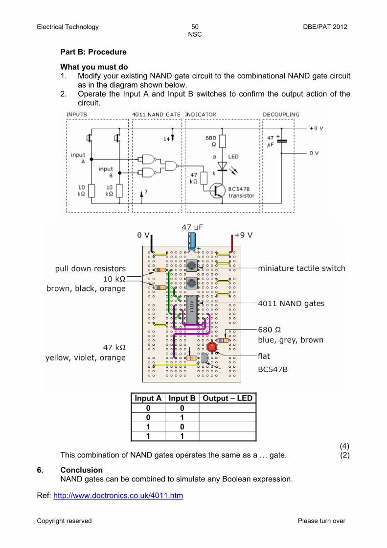
Part B: Procedure
What you must do 1. Modify your existing NAND gate circuit to the combinational NAND gate circuit
as in the diagram shown below. 2. Operate the Input A and Input B switches to confirm the output action of the
circuit.
Input A Input B Output – LED
0 0 0 1 1 0 1 1
(4) This combination of NAND gates operates the same as a … gate. (2)
6. Conclusion NAND gates can be combined to simulate any Boolean expression. Ref: http://www.doctronics.co.uk/4011.htm
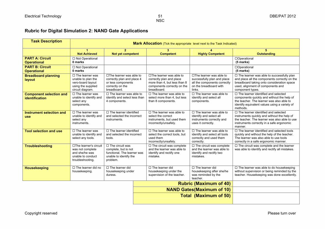
Electrical Technology 51 DBE/PAT 2012 NSC
Copyright reserved Please turn over
Rubric for Digital Simulation 2: NAND Gate Applications
Task Description Mark Allocation (Tick the appropriate level next to the Task Indicated)
1 Not Achieved
2 Not yet competent
3 Competent
4 Highly Competent
5 Outstanding
PART A: Circuit Operational
Not Operational 0 marks Operational
(5 marks) PART B: Circuit Operational
Not Operational 0 marks Operational
(5 marks) Breadboard planning layout
The learner was unable to plan the vero-board layout using the supplied circuit diagram.
The learner was able to correctly plan and place 4 or less components correctly on the breadboard.
The learner was able to correctly plan and place more than 4, but less than 8 components correctly on the breadboard.
The learner was able to successfully plan and place all the components correctly on the breadboard with links.
The learner was able to successfully plan and place all the components correctly on the breadboard taking onto consideration space used, alignment of components and component types.
Component selection and identification
The learner was unable to identify and select any components.
The learner was able to identify and select less than 4 components.
The learner was able to select more than 4, but less than 8 components.
The learner was able to identify and select all components.
The learner identified and selected components quickly and without the help of the teacher. The learner was also able to identify equivalent values using a variety of methods.
Instrument selection and use
The learner was unable to identify and select any instruments.
The learner identified and selected the incorrect instruments.
The learner was able to select the correct instruments, but used them incorrectly/unsafely.
The learner was able to identify and select all instruments correctly and uses it correctly.
The learner identified and selected instruments quickly and without the help of the teacher. The learner was also able to use instruments correctly in a safe ergonomic manner.
Tool selection and use The learner was unable to identify and select any tools.
The learner identified and selected the incorrect tools.
The learner was able to select the correct tools, but used them incorrectly/unsafely.
The learner was able to identify and select all tools correctly and used them correctly.
The learner identified and selected tools quickly and without the help of the teacher. The learner was also able to use tools correctly in a safe ergonomic manner.
Troubleshooting The learner's circuit was not complete and she/he was unable to conduct troubleshooting.
The circuit was complete, but is not functional. The learner was unable to identify the problem.
The circuit was complete and the learner was able to identify and rectify one mistake.
The circuit was complete and the learner was able to identify and rectify two mistakes.
The circuit was complete and the learner was able to identify and rectify all mistakes.
Housekeeping The learner did no housekeeping.
The learner did housekeeping under duress.
The learner did housekeeping under the supervision of the teacher.
The learner did housekeeping after she/he was reminded by the teacher.
The learner was able to do housekeeping without supervision or being reminded by the teacher. Housekeeping was done excellently.
Rubric (Maximum of 40) NAND Gates(Maximum of 10)
Total (Maximum of 50)

Electrical Technology 52 DBE/PAT 2012 NSC
Copyright reserved Please turn over
1. Purpose To practise the application of NOR gates in logic circuits. 2. The 4001 Logic IC3
The truth table of each individual gate is:
A B X 0 0 1 0 1 0 1 0 0 1 1 0
NOR gate truth table Where '0' represents a LOW voltage and '1' represents a HIGH voltage
You can investigate the behaviour of a single NOR gate using this circuit.
3 Ref: www.doctronics.com
Digital Simulation 3 Time: 3 hours Learner Name: School: Examination Number:
NOR Gate Application

Electrical Technology 53 DBE/PAT 2012 NSC
Copyright reserved Please turn over
The inputs of the gate must be connected, either to LOW or to HIGH, and must not be left open circuit. This is the function of the input switches with their pull-down resistors. To avoid loading the output of the gate, a transistor switch indicator circuit should be used.
It is good practice with CMOS circuits to insert a decoupling capacitor, 47 µF or 100 µF, across the power supply. (This helps to prevent the transfer of spikes along the power supply rails.)
Don't forget to connect pin 14 of the 4001 to +9 V and pin 7 to 0 V. Construct the NAND gate test circuit as shown below. (5 marks for a working circuit)
In the prototype circuit, it is not essential to make connections to the unused gates. However, in any final circuit, all unused CMOS inputs must be connected either to HIGH or to LOW. Make it an absolute rule that CMOS inputs are never left open circuit.
There is no problem with CMOS outputs. Worry about the inputs and leave any unused outputs unconnected.
Make use of the 4001 IC and build a logic circuit that will represent the following Boolean Function. (5 marks for a working circuit)
XBA =.
3. Conclusion
NOR gate combinations can be used to simulate any Boolean expression.
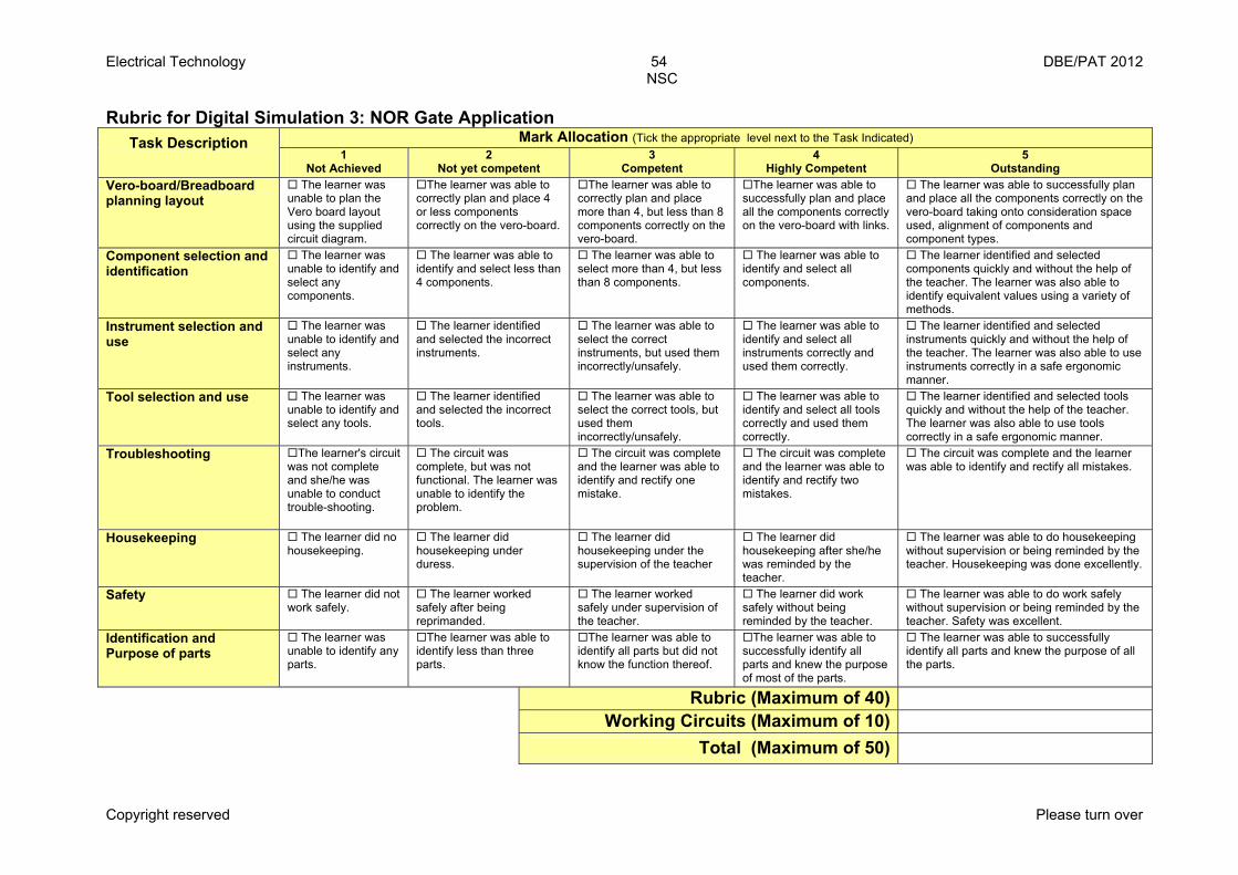
Electrical Technology 54 DBE/PAT 2012 NSC
Copyright reserved Please turn over
Rubric for Digital Simulation 3: NOR Gate Application
Mark Allocation (Tick the appropriate level next to the Task Indicated) Task Description 1
Not Achieved 2
Not yet competent 3
Competent 4
Highly Competent 5
Outstanding Vero-board/Breadboard planning layout
The learner was unable to plan the Vero board layout using the supplied circuit diagram.
The learner was able to correctly plan and place 4 or less components correctly on the vero-board.
The learner was able to correctly plan and place more than 4, but less than 8 components correctly on the vero-board.
The learner was able to successfully plan and place all the components correctly on the vero-board with links.
The learner was able to successfully plan and place all the components correctly on the vero-board taking onto consideration space used, alignment of components and component types.
Component selection and identification
The learner was unable to identify and select any components.
The learner was able to identify and select less than 4 components.
The learner was able to select more than 4, but less than 8 components.
The learner was able to identify and select all components.
The learner identified and selected components quickly and without the help of the teacher. The learner was also able to identify equivalent values using a variety of methods.
Instrument selection and use
The learner was unable to identify and select any instruments.
The learner identified and selected the incorrect instruments.
The learner was able to select the correct instruments, but used them incorrectly/unsafely.
The learner was able to identify and select all instruments correctly and used them correctly.
The learner identified and selected instruments quickly and without the help of the teacher. The learner was also able to use instruments correctly in a safe ergonomic manner.
Tool selection and use The learner was unable to identify and select any tools.
The learner identified and selected the incorrect tools.
The learner was able to select the correct tools, but used them incorrectly/unsafely.
The learner was able to identify and select all tools correctly and used them correctly.
The learner identified and selected tools quickly and without the help of the teacher. The learner was also able to use tools correctly in a safe ergonomic manner.
Troubleshooting The learner's circuit was not complete and she/he was unable to conduct trouble-shooting.
The circuit was complete, but was not functional. The learner was unable to identify the problem.
The circuit was complete and the learner was able to identify and rectify one mistake.
The circuit was complete and the learner was able to identify and rectify two mistakes.
The circuit was complete and the learner was able to identify and rectify all mistakes.
Housekeeping The learner did no housekeeping.
The learner did housekeeping under duress.
The learner did housekeeping under the supervision of the teacher
The learner did housekeeping after she/he was reminded by the teacher.
The learner was able to do housekeeping without supervision or being reminded by the teacher. Housekeeping was done excellently.
Safety The learner did not work safely.
The learner worked safely after being reprimanded.
The learner worked safely under supervision of the teacher.
The learner did work safely without being reminded by the teacher.
The learner was able to do work safely without supervision or being reminded by the teacher. Safety was excellent.
Identification and Purpose of parts
The learner was unable to identify any parts.
The learner was able to identify less than three parts.
The learner was able to identify all parts but did not know the function thereof.
The learner was able to successfully identify all parts and knew the purpose of most of the parts.
The learner was able to successfully identify all parts and knew the purpose of all the parts.
Rubric (Maximum of 40) Working Circuits (Maximum of 10)
Total (Maximum of 50)
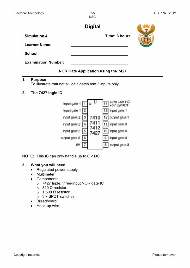
Electrical Technology 55 DBE/PAT 2012 NSC
Copyright reserved Please turn over
1. Purpose To illustrate that not all logic gates use 2 inputs only.
2. The 7427 logic IC
NOTE: This IC can only handle up to 6 V DC
3. What you will need • Regulated power supply • Multimeter • Components
o 7427 triple, three-input NOR gate IC o 820 Ω resistor o 1 500 Ω resistor o 3 x SPDT switches
• Breadboard • Hook-up wire
Digital Simulation 4 Time: 3 hours Learner Name: School: Examination Number:
NOR Gate Application using the 7427
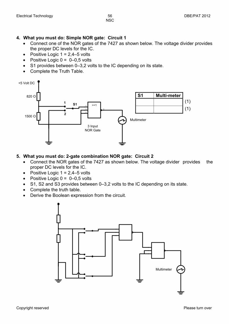
Electrical Technology 56 DBE/PAT 2012 NSC
Copyright reserved Please turn over
4. What you must do: Simple NOR gate: Circuit 1
• Connect one of the NOR gates of the 7427 as shown below. The voltage divider provides the proper DC levels for the IC.
• Positive Logic 1 = 2,4–5 volts • Positive Logic 0 = 0–0,5 volts • S1 provides between 0–3,2 volts to the IC depending on its state. • Complete the Truth Table.
5. What you must do: 2-gate combination NOR gate: Circuit 2
• Connect the NOR gates of the 7427 as shown below. The voltage divider provides the proper DC levels for the IC.
• Positive Logic 1 = 2,4–5 volts • Positive Logic 0 = 0–0,5 volts • S1, S2 and S3 provides between 0–3,2 volts to the IC depending on its state. • Complete the truth table. • Derive the Boolean expression from the circuit.
S1 Multi-meter (1)
(1)>=10
0
0 0
820 O
1500 O
+5 Volt DC
1
2
S1
Multi Meter
3 Input NOR Gate
Multimeter
Multimeter
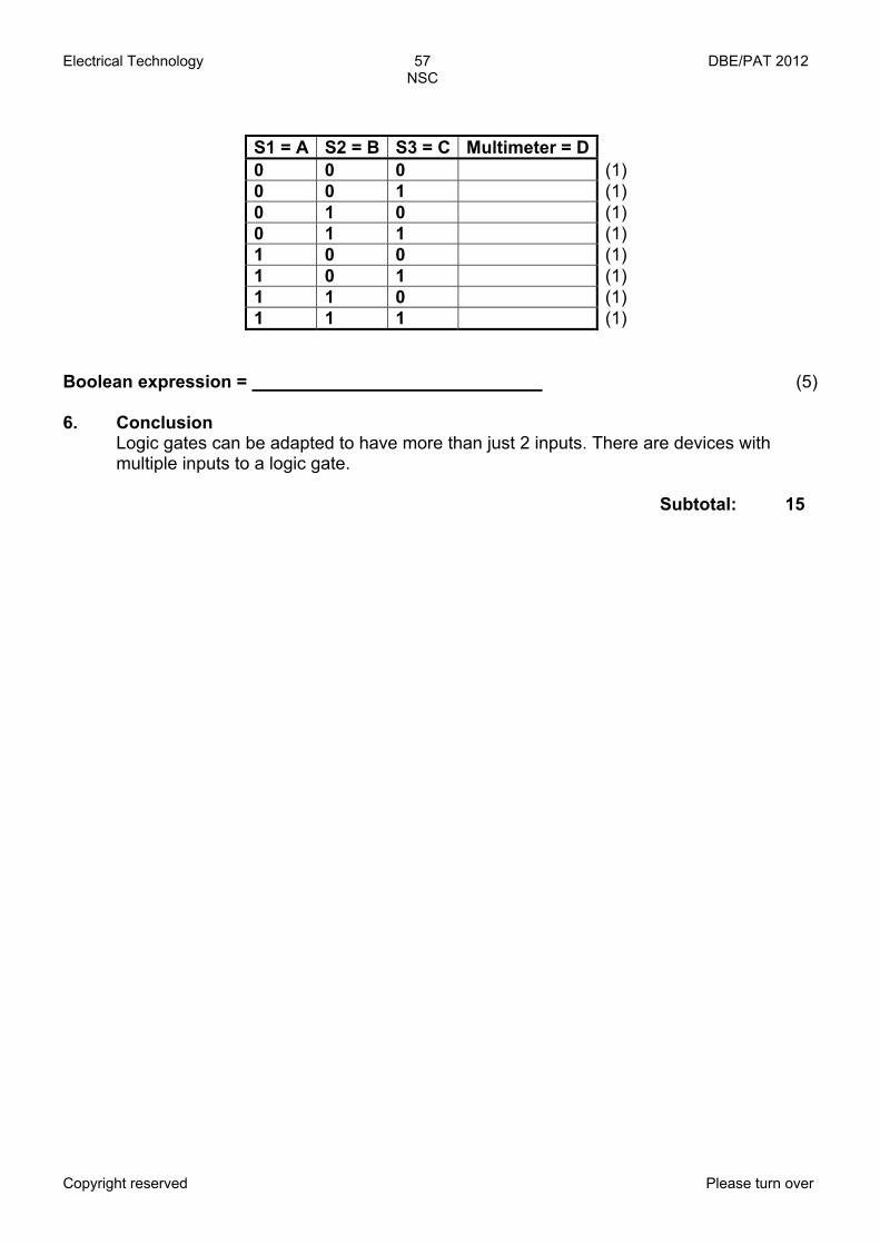
Electrical Technology 57 DBE/PAT 2012 NSC
Copyright reserved Please turn over
S1 = A S2 = B S3 = C Multimeter = D 0 0 0 (1) 0 0 1 (1) 0 1 0 (1) 0 1 1 (1) 1 0 0 (1) 1 0 1 (1) 1 1 0 (1) 1 1 1 (1)
Boolean expression = (5) 6. Conclusion
Logic gates can be adapted to have more than just 2 inputs. There are devices with multiple inputs to a logic gate.
Subtotal: 15
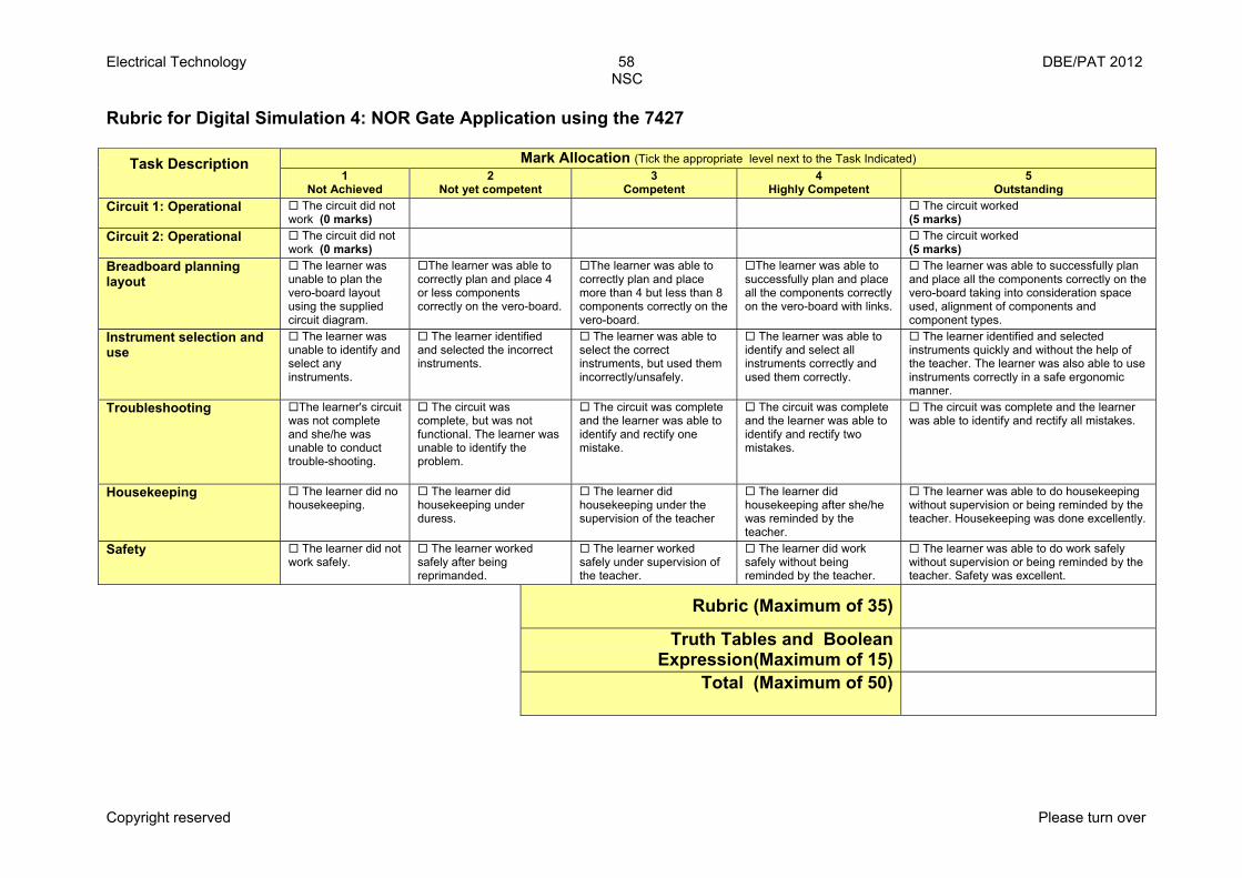
Electrical Technology 58 DBE/PAT 2012 NSC
Copyright reserved Please turn over
Rubric for Digital Simulation 4: NOR Gate Application using the 7427
Mark Allocation (Tick the appropriate level next to the Task Indicated) Task Description 1
Not Achieved 2
Not yet competent 3
Competent 4
Highly Competent 5
Outstanding Circuit 1: Operational The circuit did not
work (0 marks) The circuit worked
(5 marks) Circuit 2: Operational The circuit did not
work (0 marks) The circuit worked
(5 marks) Breadboard planning layout
The learner was unable to plan the vero-board layout using the supplied circuit diagram.
The learner was able to correctly plan and place 4 or less components correctly on the vero-board.
The learner was able to correctly plan and place more than 4 but less than 8 components correctly on the vero-board.
The learner was able to successfully plan and place all the components correctly on the vero-board with links.
The learner was able to successfully plan and place all the components correctly on the vero-board taking into consideration space used, alignment of components and component types.
Instrument selection and use
The learner was unable to identify and select any instruments.
The learner identified and selected the incorrect instruments.
The learner was able to select the correct instruments, but used them incorrectly/unsafely.
The learner was able to identify and select all instruments correctly and used them correctly.
The learner identified and selected instruments quickly and without the help of the teacher. The learner was also able to use instruments correctly in a safe ergonomic manner.
Troubleshooting The learner's circuit was not complete and she/he was unable to conduct trouble-shooting.
The circuit was complete, but was not functional. The learner was unable to identify the problem.
The circuit was complete and the learner was able to identify and rectify one mistake.
The circuit was complete and the learner was able to identify and rectify two mistakes.
The circuit was complete and the learner was able to identify and rectify all mistakes.
Housekeeping The learner did no housekeeping.
The learner did housekeeping under duress.
The learner did housekeeping under the supervision of the teacher
The learner did housekeeping after she/he was reminded by the teacher.
The learner was able to do housekeeping without supervision or being reminded by the teacher. Housekeeping was done excellently.
Safety The learner did not work safely.
The learner worked safely after being reprimanded.
The learner worked safely under supervision of the teacher.
The learner did work safely without being reminded by the teacher.
The learner was able to do work safely without supervision or being reminded by the teacher. Safety was excellent.
Rubric (Maximum of 35)
Truth Tables and Boolean Expression(Maximum of 15)
Total (Maximum of 50)

Electrical Technology 59 DBE/PAT 2012 NSC
Copyright reserved
Declaration by the Learner Declaration: I (Name) herewith declare that the work represented in this Learner Evidence (L.E) is entirely my own effort. I understand that if proven otherwise, my final results will be withheld. Signature of learner Date As far as I know, the above declaration by the learner is true and I accept that the work offered is his or her own. ___________________________________ ____________ SIGNATURE OF PARENT/GUARDIAN DATE ___________________________________ ____________ SIGNATURE OF TEACHER DATE
SCHOOL STAMP

Electrical Technology 60 DBE/PAT 2012 NSC
Copyright reserved
Working Mark sheet (A working Excel file is available from the national co-ordinator)
Teacher Name: Moderator Name: Principal Name: Signature: Signature: Signature: Date:
PAT Mark sheet Term 1 Term 2 Project
No. Name of Learner
Simulation 1 50
Simulation 2 50
Simulation 3 50
Simulation 4 50
Design and Make Part 1 80
Design and Make Part 2 20
Design And Make Total = 50
Total = 250
Term1 + Term 2 + Project M
ark
out
of 1
00
Mod
erat
ed
Mar
k
0 E.g.: John Q Citizen 45 10 30 25 30 10 20 135 54% 54% 1 2 3 4 5 6 7 8 9
10 11 12 13 14 15 16 17 18 19 20
Total Average
School Stamp


