Price $12.00 ALL MODELS SERIAL NUMBERS 6300000 AND UP SERVICE MANUAL E LECTRICAL TROUBLESHOOTING VOLUME 3 Form 172112-160216 Printed in U.S.A. THE GRASSHOPPER COMPANY Moundridge, Kansas 67107 U.S.A. (620) 345-8621 GRASSHOPPERMOWER.COM
Transcript
Price $12.00
ALL MODELSSERIAL NUMBERS 6300000 AND UP
SERVICE MANUALELECTRICAL TROUBLESHOOTING
VOLUME 3
Form 172112-160216Printed in U.S.A.
THE GRASSHOPPER COMPANYMoundridge, Kansas 67107 U.S.A.
(620) 345-8621GRASSHOPPERMOWER.COM
2
This manual has been developed to diagnose component failures only. It will not indicate a problem in the wiring or terminals. For ex-ample, if the troubleshooting guide indicates that the left steering switch is defective and replacing the left steering switch does not solve the problem; then you may have bad terminals or wiring to that switch.
Consult the operator's manual wiring diagram for the specific year and model of the ma-chine you are working on for troubleshooting. For further assistance, contact The Grass-hopper Company, service department at (620)345-8621.
TROUBLESHOOTING CONTROL RELAYS All Kubota Gasoline Models ..............................................................................................8 All Kubota Diesel Models ..................................................................................................8 Control Relay - All Kubota Models ..................................................................................10 Circuit Board Diode Problems - All Models .....................................................................10
TESTING SAFETY SYSTEM FOR PROPER OPERATION All Briggs & Kohler Models .............................................................................................12 All Kubota Models ...........................................................................................................13
BATTERY CHARGING SYSTEM All Briggs Models & Kohler Models excluding Kohler EFI Models ..................................14 All Kubota Models with Smooth Alternators . .................................................................15 All Kubota Models with Aluminum/Finned Alternators .....................................................16
ENGINE WILL NOT CRANK 124, 126, 226V and 616T Series Models ................................................................. 18-19 125 Kohler, 200 Series Models except 226V, All Briggs Big Block Models, 620T & 623T Models and all 700 Kohler Models................. ..................................... 20-21 All Kubota Models ..................................................................................................... 22-23
ENGINE WILL CRANK, BUT NOT START All Briggs & Kohler Models ..............................................................................................24 All Kubota Gasoline Models ...........................................................................................25 All Kubota Diesel Models except those with D902 Engines. ..........................................26 Kubota Diesel Models with D902 Engines ......................................................................27
ENGINE STARTS, BUT DIESWHEN STEERING LEVERS ARE BROUGHT IN OR PTO SWITCH IS ENGAGED All Models ........................................................................................................................28 ENGINE STARTS, BUT DIESWHEN KEY SWITCH IS RELEASED All Kubota Diesel Models except those with D902 Engines. ..................................... 30-31 Kubota Diesel Models with D902 Engines ......................................................................32 Briggs & Kohler Models ...................................................................................................33
TABLE OF CONTENTS
(continued)
4
TABLE OF CONTENTS(CONTINUED)
ENGINE STARTS AND RUNS, BUT WILL NOT SHUT OFF Kubota Diesel Models with D902 Engines ................................................................ 34-35
TROUBLESHOOTING PTO CLUTCH All Models except Kubota ................................................................................................36 All Kubota Models ..........................................................................................................37 Acceptable Clutch Resistance Range in Ohms ..............................................................38 High Temperature Clutch Cutout Wiring ..........................................................................39
TROUBLESHOOTING ELECTRIC LIFT Electric Lift Does Not Operate ................................................................................... 40-43 Wiring Diagram ...............................................................................................................44
HYDRAULIC LIFT DOES NOT WORK Hydraulic Dozer Electrical Troubleshooting ....................................................................45 One Piece Tilt Switch/Delay Timer Style ................................................................... 46-47
JOYSTICK WIRING TROUBLESHOOTING Joystick Wiring Troubleshooting - Total Loss of Motion...................................................48 Joystick Wiring Troubleshooting - Loss of Motion in One Direction ................................49
TRACTOR ACCESSORY HARNESS TROUBLESHOOTING All Models .................................................................................................................. 50-52
5
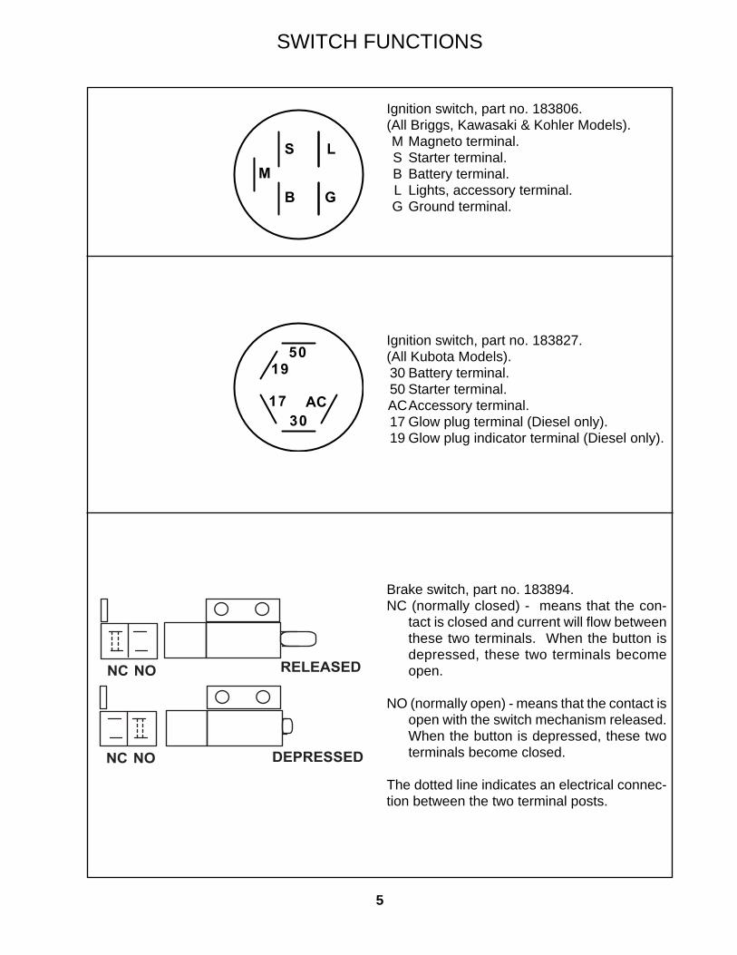
Ignition switch, part no. 183806.(All Briggs, Kawasaki & Kohler Models). M Magneto terminal. S Starter terminal. B Battery terminal. L Lights, accessory terminal. G Ground terminal.
Brake switch, part no. 183894.NC (normally closed) - means that the con-
tact is closed and current will fl ow between these two terminals. When the button is depressed, these two terminals become open.
NO (normally open) - means that the contact is open with the switch mechanism released. When the button is depressed, these two terminals become closed.
The dotted line indicates an electrical connec-tion between the two terminal posts.
SWITCH FUNCTIONS
�
��
�
�
��
�� �
�
NC NO
NC NO
RELEASED
DEPRESSED
6
Left and right steering switch, part no. 183860.NC (normally closed) - means that the con-
tact is closed with the switch mechanism released. The contact position is reversed when the switch lever is depressed.
NO (normally open) - means that the contact is open with the switch mechanism re-leased. The contact position is reversed when the switch lever is depressed.
The dotted line indicates an electrical con-nection between the two terminal posts.
PTO switch, part no. 183925.The dotted line indicates an electrical con-nection between the two terminal posts.
Seat switch, part no. 183871.The dotted line indicates an electrical con-nection between the two terminal posts.
SWITCH FUNCTIONS
��� ��
��������
���������
��
��
��
��
������
������
��������
���������
7
FUNCTION OF A RELAY
87
87A86 85
30
87a
87
30
87
87A86 85
30
86
85
87a
87
30NON-ENERGIZED
ENERGIZED
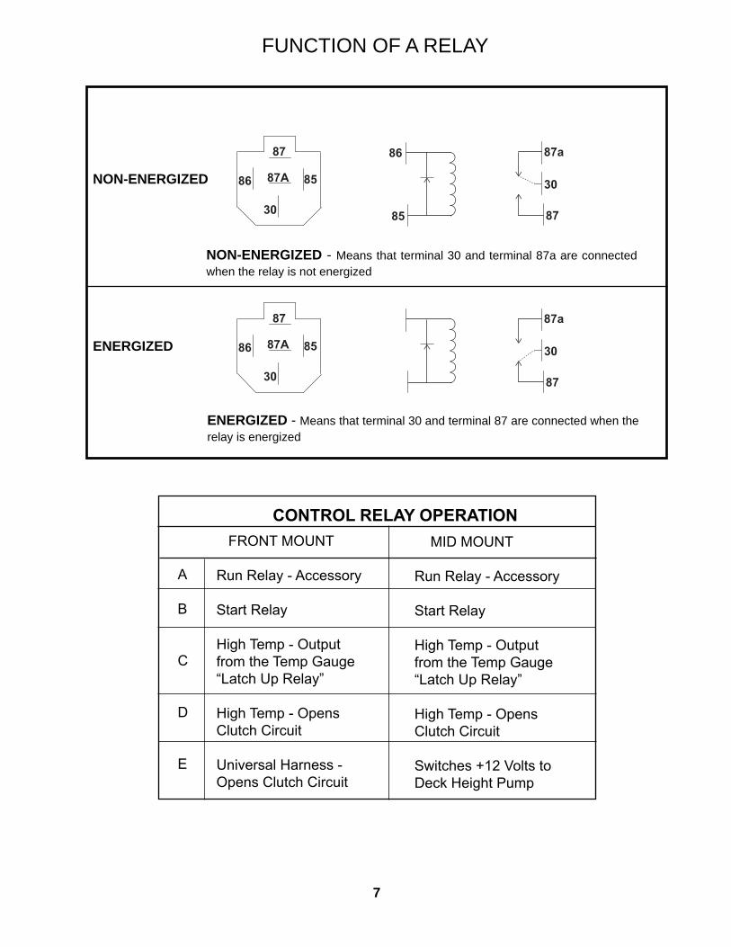
NON-ENERGIZED - Means that terminal 30 and terminal 87a are connected when the relay is not energized
ENERGIZED - Means that terminal 30 and terminal 87 are connected when the relay is energized
CONTROL RELAY OPERATION FRONT MOUNT
Run Relay - Accessory
Start Relay
High Temp - Output from the Temp Gauge“Latch Up Relay”
High Temp - OpensClutch Circuit
Universal Harness - Opens Clutch Circuit
MID MOUNT
Run Relay - Accessory
Start Relay
High Temp - Output from the Temp Gauge“Latch Up Relay”
High Temp - OpensClutch Circuit
Switches +12 Volts toDeck Height Pump
A
B
C
D
E
8
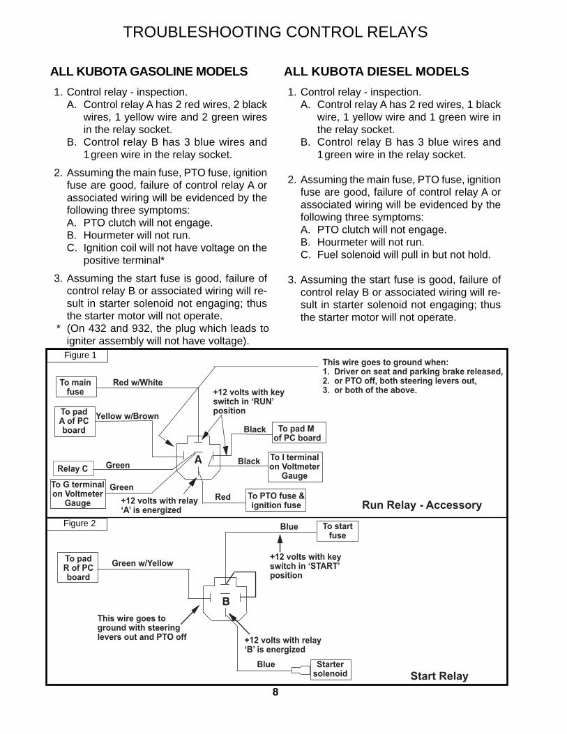
ALL KUBOTA GASOLINE MODELS 1. Control relay - inspection. A. Control relay A has 2 red wires, 2 black
wires, 1 yellow wire and 2 green wires in the relay socket.
B. Control relay B has 3 blue wires and 1 green wire in the relay socket.
2. Assuming the main fuse, PTO fuse, ignition fuse are good, failure of control relay A or associated wiring will be evidenced by the following three symptoms:
A. PTO clutch will not engage. B. Hourmeter will not run. C. Ignition coil will not have voltage on the
positive terminal*
3. Assuming the start fuse is good, failure of control relay B or associated wiring will re-sult in starter solenoid not engaging; thus the starter motor will not operate.
ALL KUBOTA DIESEL MODELS 1. Control relay - inspection. A. Control relay A has 2 red wires, 1 black
wire, 1 yellow wire and 1 green wire in the relay socket.
B. Control relay B has 3 blue wires and 1 green wire in the relay socket.
2. Assuming the main fuse, PTO fuse, ignition fuse are good, failure of control relay A or associated wiring will be evidenced by the following three symptoms:
A. PTO clutch will not engage. B. Hourmeter will not run. C. Fuel solenoid will pull in but not hold.
3. Assuming the start fuse is good, failure of control relay B or associated wiring will re-sult in starter solenoid not engaging; thus the starter motor will not operate.
TROUBLESHOOTING CONTROL RELAYS
* (On 432 and 932, the plug which leads to igniter assembly will not have voltage).
This wire goes to ground when:1. Driver on seat and parking brake released,2. or PTO off, both steering levers out,3. or both of the above.
Red w/White
Yellow w/Brown
Green
Red
Black
+12 volts with keyswitch in ‘RUN’position
To mainfuse
To padA of PCboard
Relay C
To pad M of PC board
To PTO fuse &ignition fuse+12 volts with relay
‘A’ is energized
To G terminal on Voltmeter
Gauge
Green
To I terminal on Voltmeter
GaugeBlack
Run Relay - Accessory
Green w/Yellow
Blue
Blue
This wire goes toground with steeringlevers out and PTO off
+12 volts with keyswitch in ‘START’position
To padR of PCboard
To startfuse
Startersolenoid
+12 volts with relay‘B’ is energized
Start Relay
Figure 1
Figure 2
9
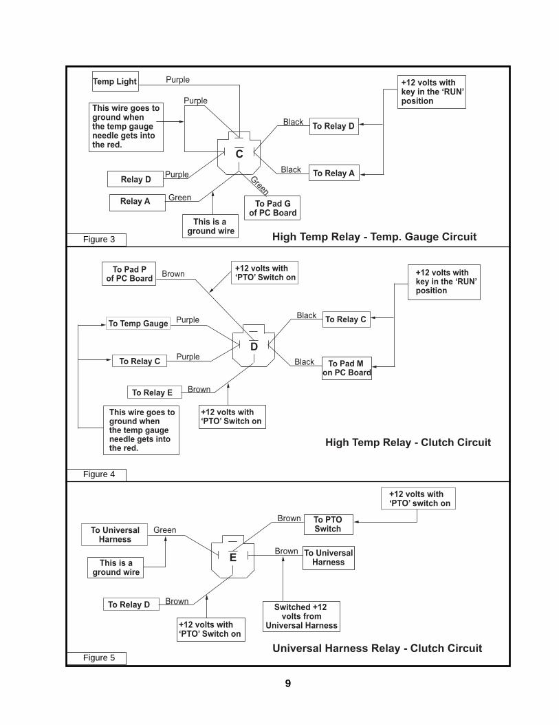
Purple +12 volts withkey in the ‘RUN’position
This wire goes toground whenthe temp gaugeneedle gets into the red.
Relay D
Temp Light
C
Relay A
This is a ground wire
To Pad Gof PC Board
To Relay A
To Relay D
Purple
Purple
Green
Green
Black
Black
High Temp Relay - Temp. Gauge Circuit
Brown +12 volts with‘PTO’ Switch on
To Temp Gauge
To Relay CD
To Relay E
To Pad Pof PC Board
To Pad M on PC Board
To Relay CPurple
Black
Black
Purple
Brown
+12 volts with‘PTO’ Switch on
This wire goes toground whenthe temp gaugeneedle gets into the red.
+12 volts withkey in the ‘RUN’position
High Temp Relay - Clutch Circuit
To UniversalHarness
This is aground wire
E
To Relay D
To UniversalHarness
To PTOSwitchGreen
Brown
Brown
Brown
+12 volts with‘PTO’ Switch on
+12 volts with‘PTO’ switch on
Switched +12 volts from
Universal Harness
Universal Harness Relay - Clutch Circuit
Figure 3
Figure 4
Figure 5
10
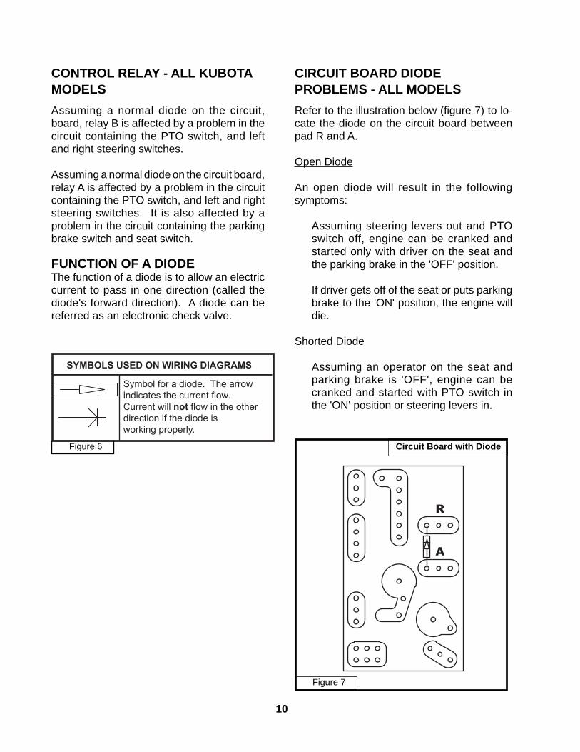
CONTROL RELAY - ALL KUBOTA MODELSAssuming a normal diode on the circuit, board, relay B is affected by a problem in the circuit containing the PTO switch, and left and right steering switches.
Assuming a normal diode on the circuit board, relay A is affected by a problem in the circuit containing the PTO switch, and left and right steering switches. It is also affected by a problem in the circuit containing the parking brake switch and seat switch.
FUNCTION OF A DIODEThe function of a diode is to allow an electric current to pass in one direction (called the diode's forward direction). A diode can be referred as an electronic check valve.
CIRCUIT BOARD DIODE PROBLEMS - ALL MODELSRefer to the illustration below (fi gure 7) to lo-cate the diode on the circuit board between pad R and A.
Open Diode
An open diode will result in the following symptoms:
Assuming steering levers out and PTO switch off, engine can be cranked and started only with driver on the seat and the parking brake in the 'OFF' position.
If driver gets off of the seat or puts parking brake to the 'ON' position, the engine will die.
Shorted Diode
Assuming an operator on the seat and parking brake is 'OFF', engine can be cranked and started with PTO switch in the 'ON' position or steering levers in.
Circuit Board with Diode
A
R
Symbol for a diode. The arrowindicates the current flow. Current will not flow in the other direction if the diode isworking properly.
SYMBOLS USED ON WIRING DIAGRAMS
Figure 6
Figure 7
11
THIS PAGE IS INTENTIONALLY LEFT BLANK
12
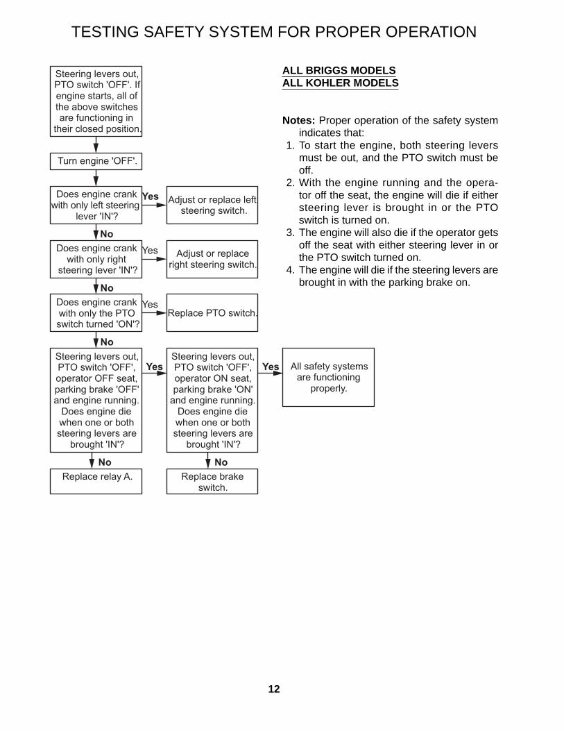
TESTING SAFETY SYSTEM FOR PROPER OPERATION
ALL BRIGGS MODELSALL KOHLER MODELS
Notes: Proper operation of the safety system indicates that:
1. To start the engine, both steering levers must be out, and the PTO switch must be off.
2. With the engine running and the opera-tor off the seat, the engine will die if either steering lever is brought in or the PTO switch is turned on.
3. The engine will also die if the operator gets off the seat with either steering lever in or the PTO switch turned on.
4. The engine will die if the steering levers are brought in with the parking brake on.
Steering levers out, PTO switch 'OFF'. If engine starts, all of the above switches are functioning in
their closed position.
Turn engine 'OFF'.
Does engine crank with only left steering
lever 'IN'?
Adjust or replace left steering switch.
Yes
NoDoes engine crank
with only right steering lever 'IN'?
Does engine crank with only the PTO switch turned 'ON'?
Steering levers out, PTO switch 'OFF', operator OFF seat, parking brake 'OFF' and engine running.
Does engine die when one or both steering levers are
and engine running. Does engine die when one or both steering levers are
brought 'IN'?
Replace brake switch.
No
Yes
Adjust or replace right steering switch.
Yes
All safety systems are functioning
properly.
Yes
No
13
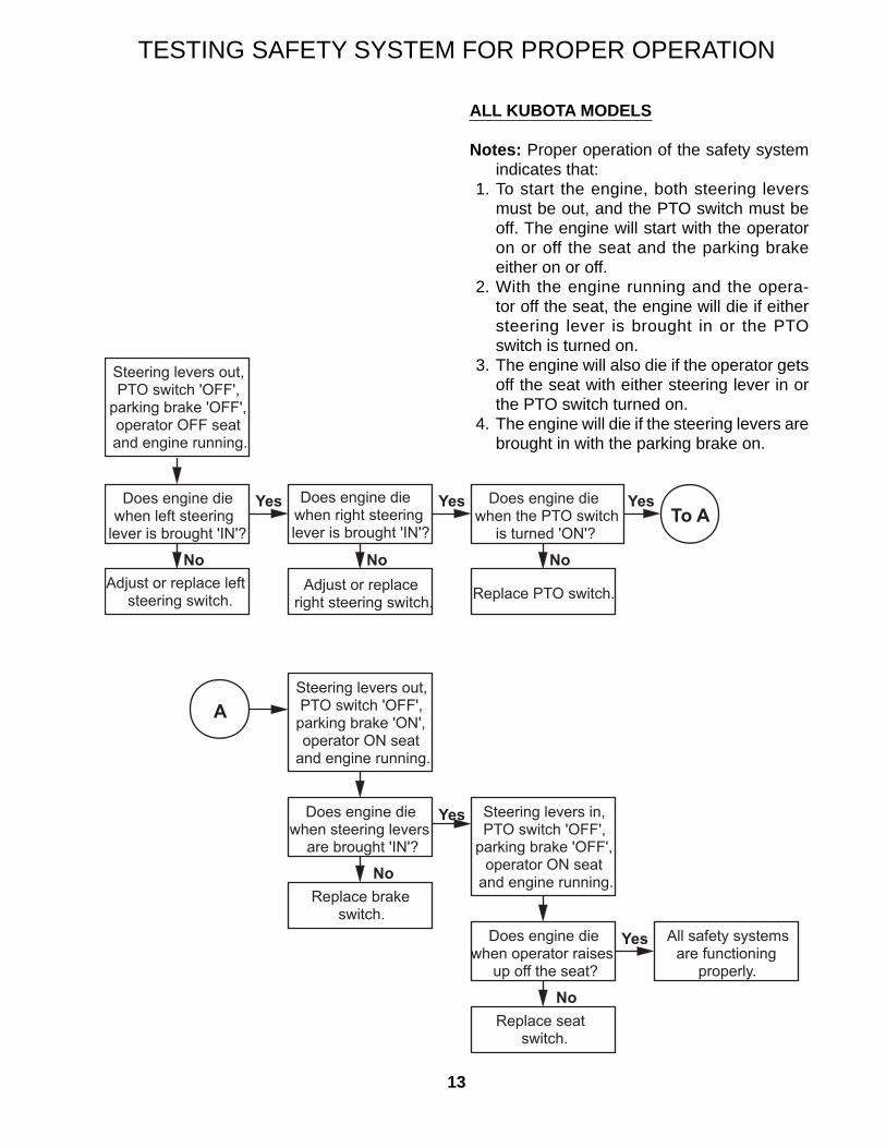
TESTING SAFETY SYSTEM FOR PROPER OPERATION
ALL KUBOTA MODELS
Notes: Proper operation of the safety system indicates that:
1. To start the engine, both steering levers must be out, and the PTO switch must be off. The engine will start with the operator on or off the seat and the parking brake either on or off.
2. With the engine running and the opera-tor off the seat, the engine will die if either steering lever is brought in or the PTO switch is turned on.
3. The engine will also die if the operator gets off the seat with either steering lever in or the PTO switch turned on.
4. The engine will die if the steering levers are brought in with the parking brake on.
Steering levers out, PTO switch 'OFF',
parking brake 'OFF', operator OFF seat and engine running.
Does engine die when left steering
lever is brought 'IN'?
Adjust or replace left steering switch.
Does engine die when right steering lever is brought 'IN'?
Yes
NoAdjust or replace
right steering switch.
No
Does engine die when the PTO switch
is turned 'ON'?
Yes
Replace PTO switch.
No
YesTo A
ASteering levers out, PTO switch 'OFF',
parking brake 'ON', operator ON seat
and engine running.
Does engine die when steering levers
are brought 'IN'?
Replace brake switch.
Yes
No
Steering levers in, PTO switch 'OFF',
parking brake 'OFF', operator ON seat
and engine running.
Does engine die when operator raises
up off the seat?
Replace seat switch.
Yes
No
All safety systems
properly.are functioning
14
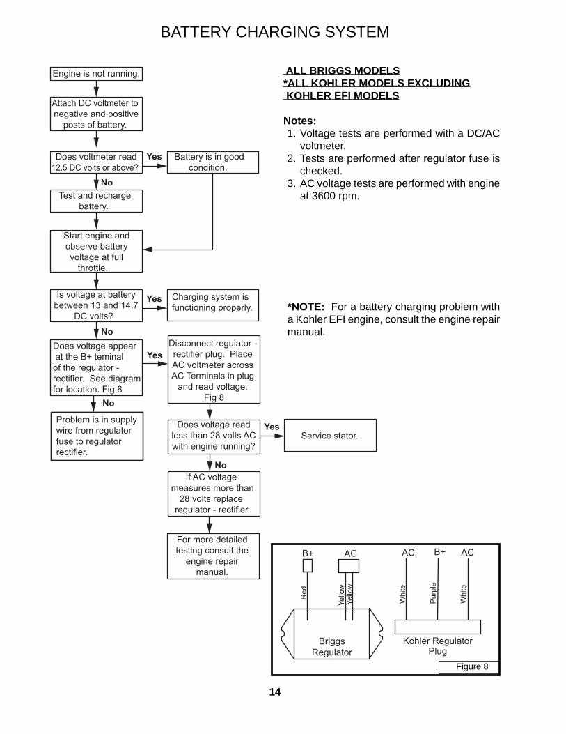
ALL BRIGGS MODELS*ALL KOHLER MODELS EXCLUDING KOHLER EFI MODELS
Notes: 1. Voltage tests are performed with a DC/AC
voltmeter. 2. Tests are performed after regulator fuse is
checked. 3. AC voltage tests are performed with engine
at 3600 rpm.
BATTERY CHARGING SYSTEM
*NOTE: For a battery charging problem with a Kohler EFI engine, consult the engine repair manual.
Engine is not running.
Attach DC voltmeter to negative and positive
posts of battery.
Does voltmeter read12.5 DC volts or above?
Test and rechargebattery.
Battery is in goodcondition.
Yes
No
Start engine andobserve batteryvoltage at full
throttle.
Is voltage at batterybetween 13 and 14.7
DC volts?
Does voltage appear at the B+ teminalof the regulator - rectifier. See diagram for location. Fig 8
NoDisconnect regulator - rectifier plug. Place AC voltmeter across AC Terminals in plug
and read voltage. Fig 8
Charging system isfunctioning properly.
Yes
Service stator.Yes
No
Does voltage readless than 28 volts ACwith engine running?
If AC voltage measures more than
28 volts replace regulator - rectifier.
For more detailedtesting consult the
engine repairmanual.
Problem is in supplywire from regulatorfuse to regulatorrectifier.
No
Yes
B+ AC
Red
Yello
wYe
llow
BriggsRegulator
B+ AC
Whi
te
Pur
ple
Whi
te
AC
Kohler RegulatorPlug
Figure 8
15*voltage may vary + or - 3 volts.
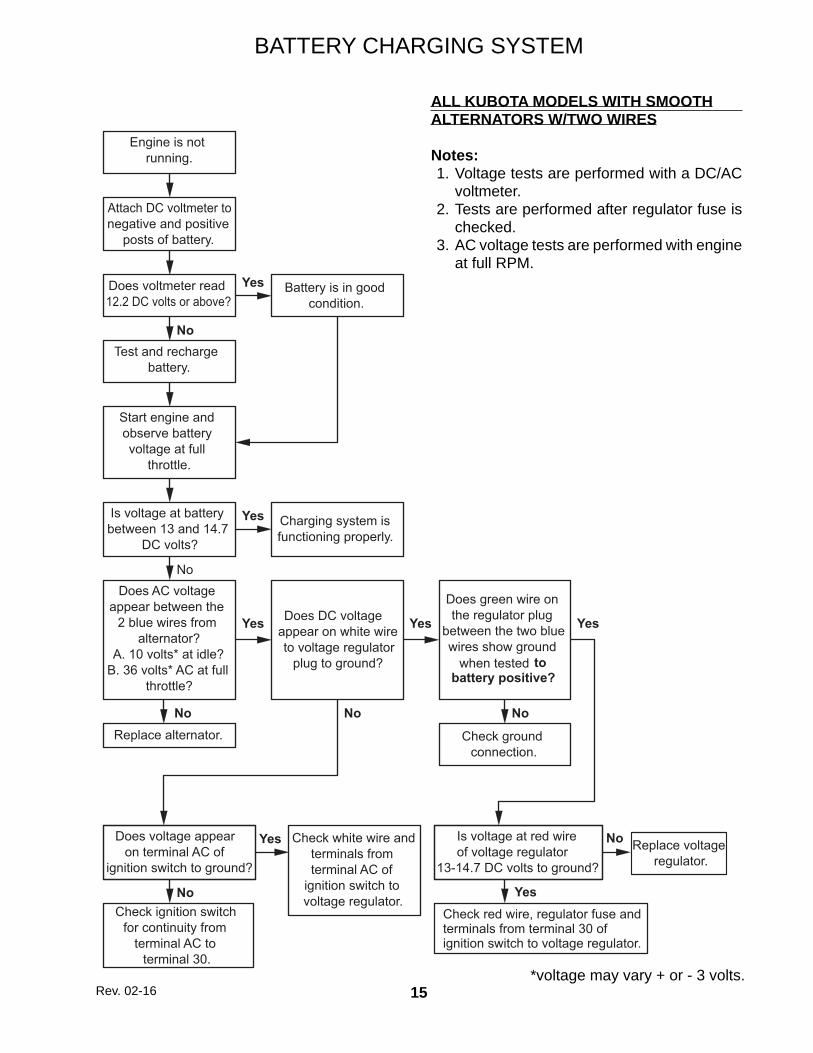
BATTERY CHARGING SYSTEM
ALL KUBOTA MODELS WITH SMOOTHALTERNATORS W/TWO WIRES
Notes: 1. Voltage tests are performed with a DC/AC
voltmeter. 2. Tests are performed after regulator fuse is
checked. 3. AC voltage tests are performed with engine
at full RPM.
Engine is not running.
Attach DC voltmeter to negative and positive
posts of battery.
Does voltmeter read 12.2 DC volts or above?
Test and recharge battery.
Battery is in good condition.
Yes
No
Start engine and observe battery voltage at full
throttle.
Is voltage at battery between 13 and 14.7
DC volts?
Does AC voltage appear between the
2 blue wires from alternator?
A. 10 volts* at idle?B. 36 volts* AC at full
throttle?
No
Replace alternator.
Charging system is functioning properly.
Yes
No
Does DC voltage appear on white wire to voltage regulator
plug to ground?
Does voltage appear on terminal AC of
ignition switch to ground?
No
Yes
Does green wire on the regulator plug
between the two blue wires show ground
when tested to battery positive?
Check ground connection.
No
Yes
Check ignition switch for continuity from
terminal AC to terminal 30.
No
Check white wire and terminals from terminal AC of
ignition switch to voltage regulator.
Yes Is voltage at red wire of voltage regulator
13-14.7 DC volts to ground?
Replace voltage regulator.
No
Check red wire, regulator fuse andterminals from terminal 30 of ignition switch to voltage regulator.
Yes
Yes
Rev. 02-16
16
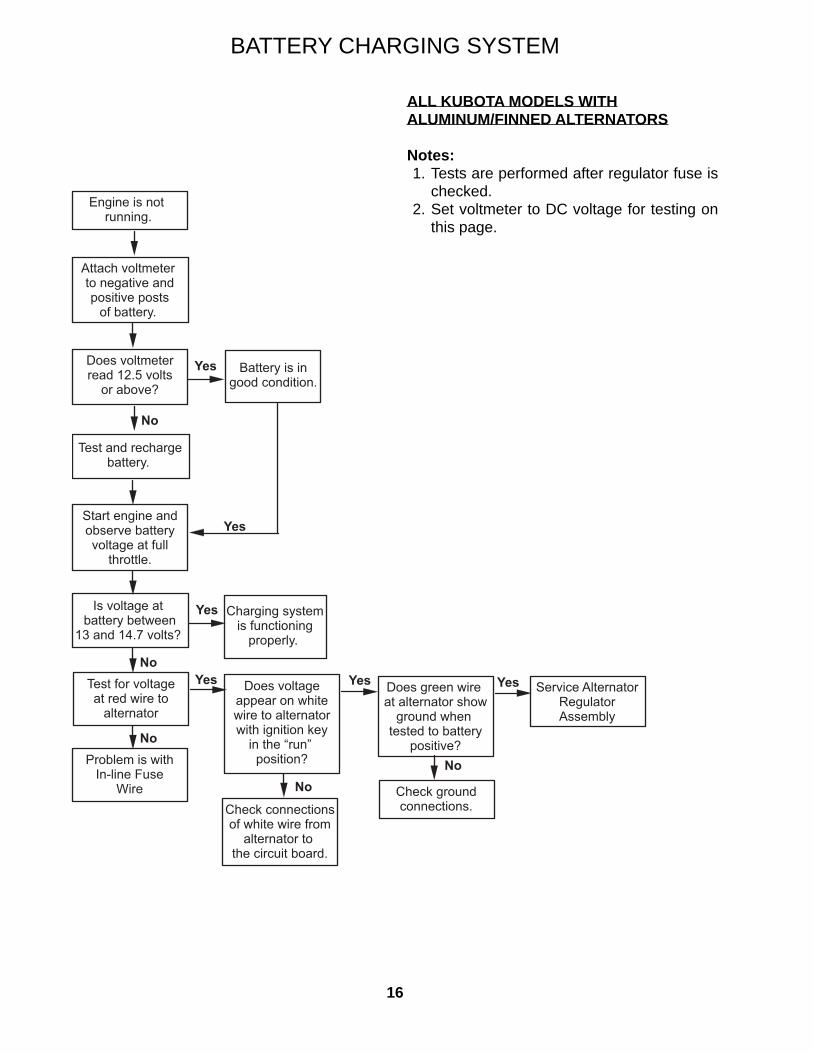
ALL KUBOTA MODELS WITH ALUMINUM/FINNED ALTERNATORS
Notes: 1. Tests are performed after regulator fuse is
checked. 2. Set voltmeter to DC voltage for testing on
this page.
BATTERY CHARGING SYSTEM
Attach voltmeter to negative andpositive posts
of battery.
Does voltmeter read 12.5 volts
or above?
Test and rechargebattery.
Battery is in good condition.
Yes
No
Start engine and observe battery voltage at full
throttle.
Is voltage at battery between
13 and 14.7 volts?
Test for voltageat red wire to
alternator
No
Charging systemis functioning
properly.
Yes
Yes
Engine is not running.
NoProblem is with
In-line FuseWire
Does voltageappear on whitewire to alternatorwith ignition key
in the “run” position?
Yes
No
Check connectionsof white wire from
alternator to the circuit board.
Does green wire at alternator show
ground when tested to battery
positive?
Yes
No
Check groundconnections.
Yes Service AlternatorRegulatorAssembly
17
THIS PAGE IS INTENTIONALLY LEFT BLANK
18
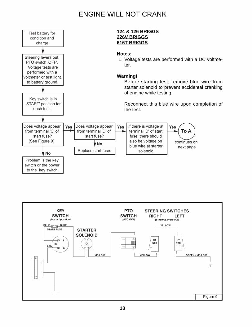
ENGINE WILL NOT CRANK
� ��
� �
�
�
�
��� ���
����
� ������
�������������������
�� ����!���
�� ��"��
���� �!�#� ����
����
$���������$����""�
���!�������������� ����������"�
���%%���&�'%(%����)��
���
����
Test battery for condition and
charge.
Steering levers out, PTO switch 'OFF'. Voltage tests are performed with a
voltmeter or test light to battery ground.
Key switch is in'START' position for
each test.
Does voltage appear from terminal 'C' of
start fuse?(See Figure 9)
Problem is the key switch or the power to the key switch.
Replace start fuse.
Does voltage appear from terminal 'D' of
start fuse?
Yes If there is voltage at terminal 'D' of start fuse, there should also be voltage on blue wire at starter
solenoid.
Yes
No
YesTo A
continues on next page
No
124 & 126 BRIGGS226V BRIGGS616T BRIGGS
Notes: 1. Voltage tests are performed with a DC voltme-
ter.
Warning! Before starting test, remove blue wire from
starter solenoid to prevent accidental cranking of engine while testing.
Reconnect this blue wire upon completion of the test.
Figure 9
19
Fuse Block Test Points
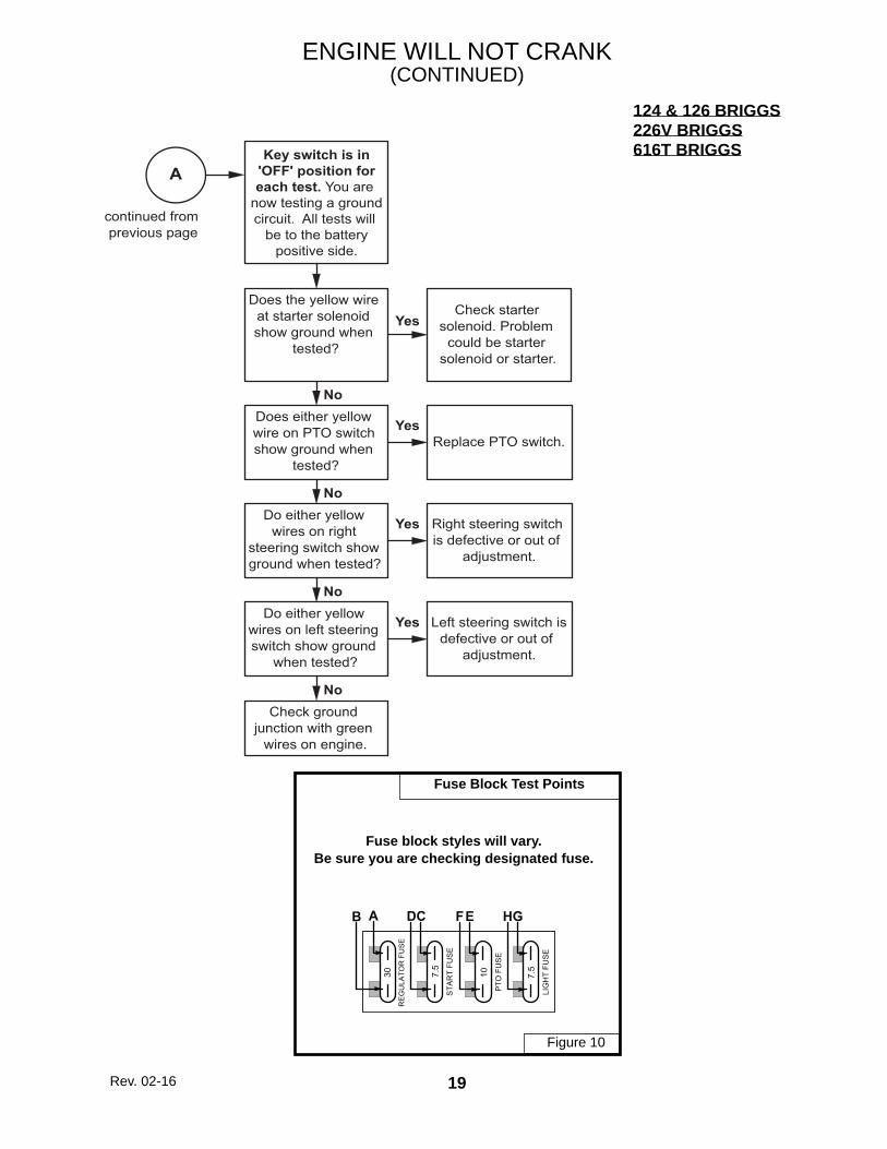
ENGINE WILL NOT CRANK(CONTINUED)
STA
RT
FUS
E
30
7.5
RE
GU
LATO
R F
US
E
LIG
HT
FUS
E
GHCDAB
10P
TO F
US
E
EF
7.5
AKey switch is in
'OFF' position foreach test. You are
now testing a groundcircuit. All tests will
be to the batterypositive side.
Does the yellow wire at starter solenoid show ground when
tested?
Does either yellow wire on PTO switch show ground when
tested?
Check starter solenoid. Problem
could be starter solenoid or starter.
Yes
No
Replace PTO switch.Yes
Do either yellow wires on right
steering switch show ground when tested?
No
Right steering switch is defective or out of
adjustment.
Yes
Do either yellow wires on left steering switch show ground
when tested?
No
Left steering switch is defective or out of
adjustment.
Yes
Check ground junction with green
wires on engine.
No
continued from previous page
124 & 126 BRIGGS226V BRIGGS616T BRIGGS
Fuse block styles will vary.Be sure you are checking designated fuse.
Figure 10
Rev. 02-16
20
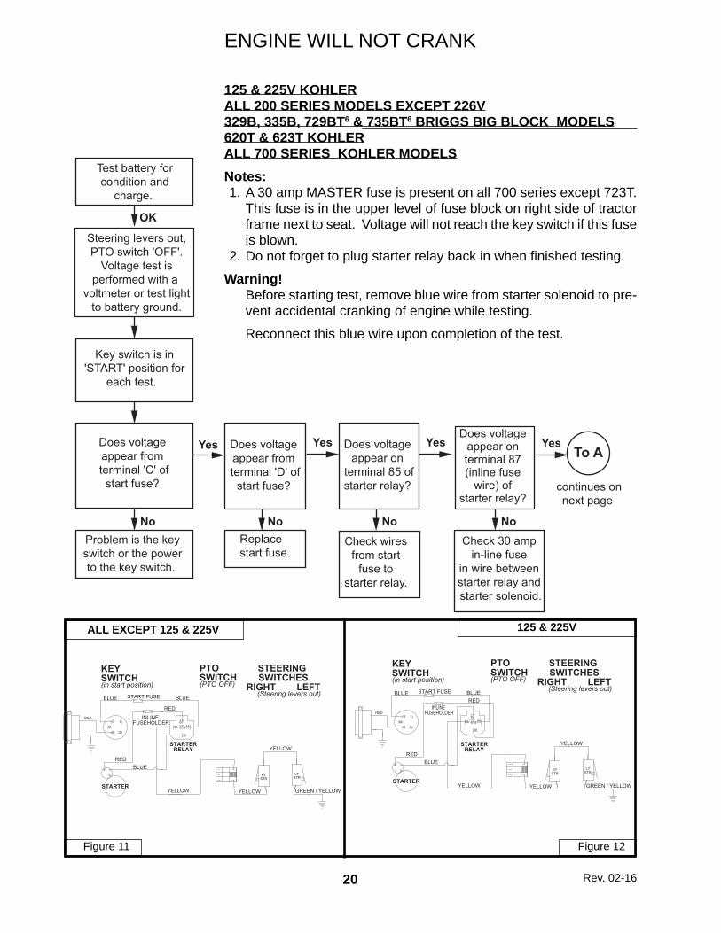
ENGINE WILL NOT CRANK
125 & 225V KOHLERALL 200 SERIES MODELS EXCEPT 226V329B, 335B, 729BT6 & 735BT6 BRIGGS BIG BLOCK MODELS620T & 623T KOHLERALL 700 SERIES KOHLER MODELSNotes: 1. A 30 amp MASTER fuse is present on all 700 series except 723T.
This fuse is in the upper level of fuse block on right side of tractor frame next to seat. Voltage will not reach the key switch if this fuse is blown.
2. Do not forget to plug starter relay back in when fi nished testing.
Warning! Before starting test, remove blue wire from starter solenoid to pre-
vent accidental cranking of engine while testing.
Reconnect this blue wire upon completion of the test.
KEYSWITCH(in start position)
PTOSWITCH(PTO OFF)
STEERING SWITCHES
RIGHT LEFT (Steering levers out)
BLUE START FUSE
RED
INLINE FUSEHOLDER
STARTERRELAY
STARTERGREEN / YELLOW
RTSTR
LTSTR
SM
B G
L 8786 87a85
30
YELLOW YELLOW
YELLOW
RED
RED
BLUE
BLUE
KEYSWITCH(in start position)
PTOSWITCH(PTO OFF)
STEERING SWITCHES
RIGHT LEFT (Steering levers out)
BLUE START FUSE
REDINLINE
FUSEHOLDER
STARTERRELAY
STARTERGREEN / YELLOW
RTSTR
LTSTR
SM
B G
L 8786 87a85
30
YELLOW YELLOW
YELLOW
RED
RED
BLUE
BLUE
ALL EXCEPT 125 & 225V 125 & 225V
Figure 11 Figure 12
Test battery forcondition and
charge.
Steering levers out,PTO switch 'OFF'.
Voltage test isperformed with a
voltmeter or test lightto battery ground.
Does voltage appear from terminal 'C' ofstart fuse?
Problem is the keyswitch or the powerto the key switch.
Replace start fuse.
Does voltage appear from terminal 'D' ofstart fuse?
Yes
No
Does voltage appear on
terminal 85 ofstarter relay?
Yes
No
YesTo A
continues onnext page
Check wires from start
fuse to starter relay.
No
OK
Does voltage appear on terminal 87 (inline fuse
wire) of starter relay?
Check 30 amp in-line fuse
in wire between starter relay and starter solenoid.
No
Yes
Key switch is in'START' position for
each test.
Rev. 02-16
21
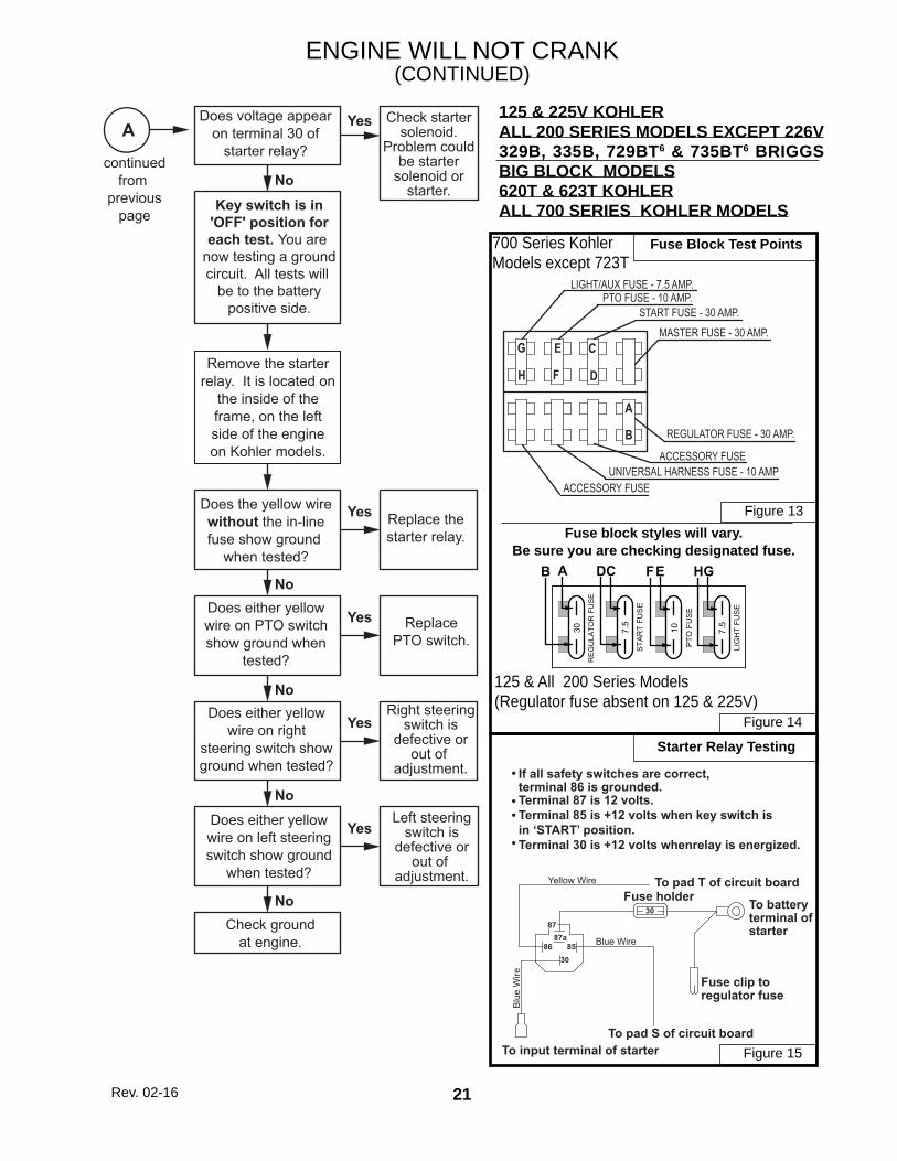
ENGINE WILL NOT CRANK(CONTINUED)
125 & 225V KOHLERALL 200 SERIES MODELS EXCEPT 226V329B, 335B, 729BT6 & 735BT6 BRIGGS BIG BLOCK MODELS620T & 623T KOHLERALL 700 SERIES KOHLER MODELS
Blu
e W
ire
Blue Wire
Yellow Wire
To input terminal of starterTo pad S of circuit board
Fuse clip toregulator fuse
To batteryterminal ofstarter
Fuse holderTo pad T of circuit board
If all safety switches are correct,terminal 86 is grounded.Terminal 87 is 12 volts.Terminal 85 is +12 volts when key switch is in ‘START’ position.Terminal 30 is +12 volts whenrelay is energized.
•
••
•
30
8787a
858630
Starter Relay Testing
Fuse Block Test Points
STA
RT
FUS
E
30
7.5
RE
GU
LATO
R F
US
E
LIG
HT
FUS
E
GHCDAB
10P
TO F
US
E
EF
7.5
700 Series Kohler Models except 723T
125 & All 200 Series Models(Regulator fuse absent on 125 & 225V)
Yes
No
Yes
No
Yes
No
Yes
No
Yes
No
ADoes voltage appear
on terminal 30 ofstarter relay?
continuedfrom
previouspage
Check startersolenoid.
Problem couldbe starter
solenoid orstarter.
Remove the starterrelay. It is located on
the inside of theframe, on the leftside of the engineon Kohler models.
Does the yellow wirewithout the in-linefuse show ground
when tested?
Replace thestarter relay.
ReplacePTO switch.
Does either yellowwire on PTO switchshow ground when
tested?
Does either yellowwire on right
steering switch showground when tested?
Right steeringswitch is
defective orout of
adjustment.
Does either yellowwire on left steeringswitch show ground
when tested?
Check groundat engine.
Left steeringswitch is
defective orout of
adjustment.
Key switch is in'OFF' position foreach test. You are
now testing a groundcircuit. All tests will
be to the batterypositive side.
Fuse block styles will vary.Be sure you are checking designated fuse.
REGULATOR FUSE - 30 AMP.
LIGHT/AUX FUSE - 7.5 AMP.PTO FUSE - 10 AMP.
START FUSE - 30 AMP.
UNIVERSAL HARNESS FUSE - 10 AMP
MASTER FUSE - 30 AMP.
ACCESSORY FUSE
ACCESSORY FUSE
G
B
C
D
A
E
FH
Figure 15
Figure 14
Figure 13
Rev. 02-16
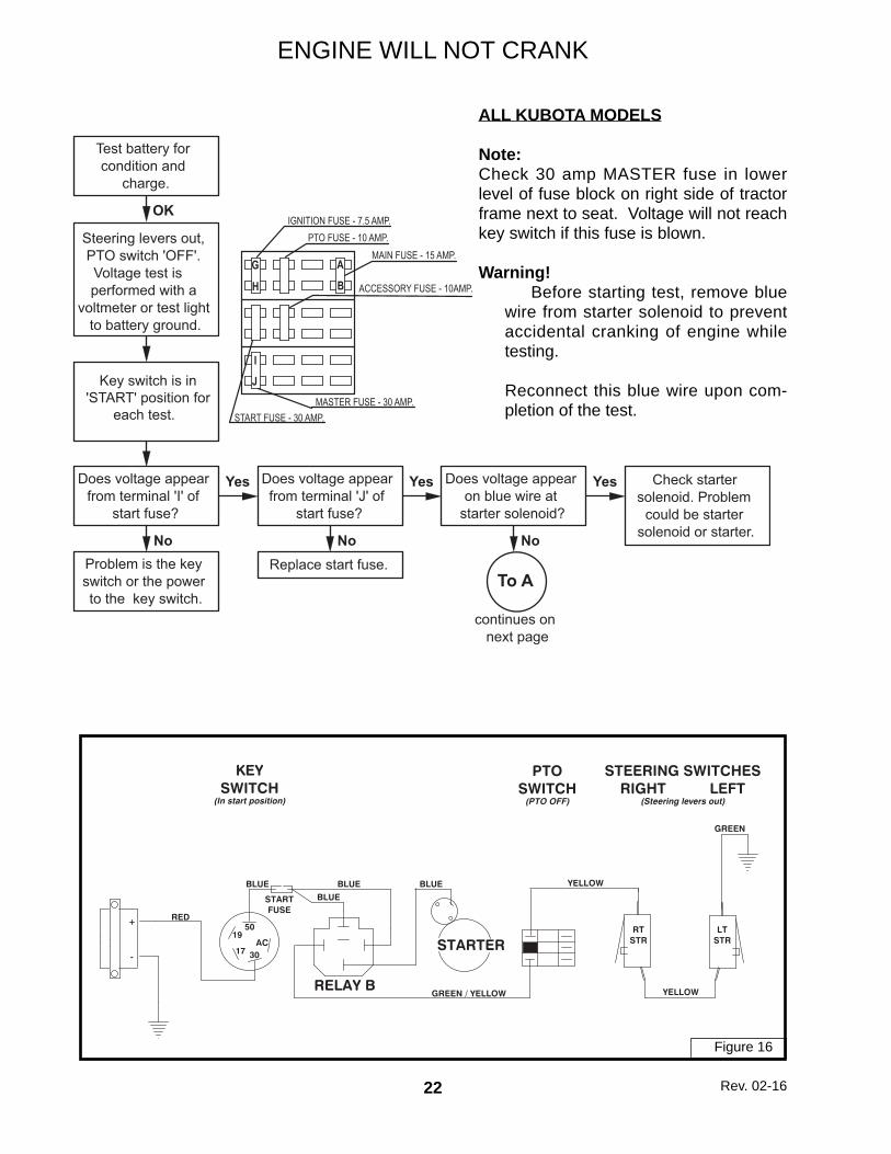
22
Test battery for condition and
charge.
Steering levers out, PTO switch 'OFF'. Voltage test is performed with a
voltmeter or test light to battery ground.
Does voltage appear from terminal 'I' of
start fuse?
Problem is the key switch or the power to the key switch.
Replace start fuse.
Does voltage appear from terminal 'J' of
start fuse?
Yes
No
Does voltage appear on blue wire at
starter solenoid?
Yes
No
Yes
To A
continues on next page
Check starter solenoid. Problem
could be starter solenoid or starter.No
OK
Key switch is in'START' position for
each test.
ENGINE WILL NOT CRANK
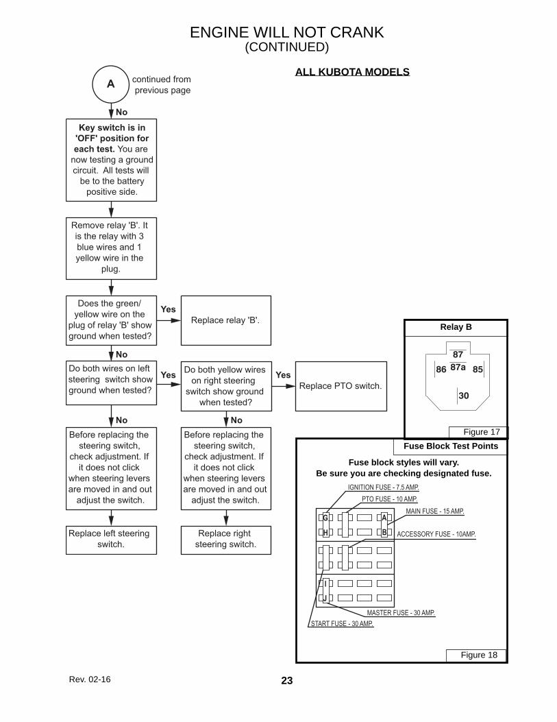
ALL KUBOTA MODELS
Note:Check 30 amp MASTER fuse in lower level of fuse block on right side of tractor frame next to seat. Voltage will not reach key switch if this fuse is blown.
Warning! Before starting test, remove blue
wire from starter solenoid to prevent accidental cranking of engine while testing.
Reconnect this blue wire upon com-pletion of the test.
Do both wires on left steering switch show ground when tested?
Replace relay 'B'.Yes
NoDo both yellow wires
on right steering switch show ground
when tested?
Yes
Before replacing the steering switch,
check adjustment. If it does not click
when steering levers are moved in and out
adjust the switch.
No
Replace left steering switch.
No
Remove relay 'B'. It is the relay with 3 blue wires and 1 yellow wire in the
plug.
A
Replace PTO switch.
Before replacing the steering switch,
check adjustment. If it does not click
when steering levers are moved in and out
adjust the switch.
No
Replace right steering switch.
Yes
continued from previous page
Key switch is in'OFF' position foreach test. You are
now testing a groundcircuit. All tests will
be to the batterypositive side.
Fuse block styles will vary.Be sure you are checking designated fuse.
START FUSE - 30 AMP.
IGNITION FUSE - 7.5 AMP.PTO FUSE - 10 AMP.
MAIN FUSE - 15 AMP.
ACCESSORY FUSE - 10AMP.
MASTER FUSE - 30 AMP.
G
B
A
I
J
H
Figure 18
Figure 17
Rev. 02-16
24
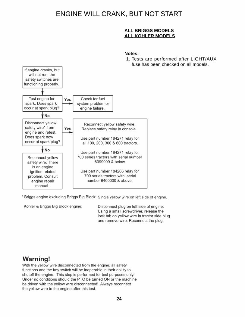
If engine cranks, butwill not run; the
safety switches arefunctioning properly.
Test engine forspark. Does spark
occur at spark plug?
Disconnect yellowsafety wire* fromengine and retest.Does spark nowoccur at spark plug?
Reconnect yellowsafety wire. There
is an engineignition related
problem. Consultengine repair
manual.
Reconnect yellow safety wire. Replace safety relay in console.
Use part number 184271 relay for all 100, 200, 300 & 600 tractors.
Use part number 184271 relay for
700 series tractors with serial number 6399999 & below.
Use part number 184266 relay for 700 series tractors with serial
number 6400000 & above.
Yes
No
Check for fuelsystem problem or
engine failure.
Yes
No
Warning!
* Briggs engine excluding Briggs Big Block:
Kohler & Briggs Big Block engine:
Single yellow wire on left side of engine.
Disconnect plug on left side of engine.Using a small screwdriver, release thelock tab on yellow wire in tractor side plugand remove wire. Reconnect the plug.
With the yellow wire disconnected from the engine, all safetyfunctions and the key switch will be inoperable in their ability toshutoff the engine. This step is performed for test purposes only.Under no conditions should the PTO be turned ON or the machinebe driven with the yellow wire disconnected! Always reconnectthe yellow wire to the engine after this test.
ENGINE WILL CRANK, BUT NOT START
ALL BRIGGS MODELSALL KOHLER MODELS
Notes: 1. Tests are performed after LIGHT/AUX
fuse has been checked on all models.
25
ENGINE WILL CRANK, BUT NOT START
ALL KUBOTA GASOLINE MODELS
Notes: 1. All tests are made with wires in place on
their respective switches. 2. Refer to fuse block diagram for terminal
locations. 3. Refer to “Troubleshooting Control Relays”
for information on the diode and control relays.
4. If engine will crank, control relay “B” is functioning properly. This means that the PTO switch, right steering switch and left steering switch are functioning properly.
Fuse Block Test Points
� � �
�
� � �
� �
� ' � � � ) � �
� � � � � � �
� � ' � � � "
! " � � �
� $ % � � � ' %� ' � "
� � & � � � � �
� � & � � � � �
� ! " � � �
� �
� � � � � �� � � � � . � � � � � � � � � � �
/ � � %
) # �
� $ % � � � ' %
) # �
� " � � � �
� " " ' �
& � ! � ' � %
�
�
* For models 329/729 & 432/932, test for volt-age at red wire in white 2-way plug located di-rectly below carburetor on engine.
No
Yes
Yes
No
Yes
No
Yes
No
No
Yes
Steering levers out,
PTO switch 'OFF'.
Voltage tests are
performed with a
voltmeter or test light
to battery ground
(negative post).
Key switch is in
'RUN' position for
each test until
otherwise noted.
Does voltage appear
from black wire on
positive terminal of
ignition coil to
ground? *
Problem is in ignition
coil or distributor.
Consult Kubota
engine manual for
repair.
Replace control relay
A.
Does voltage appear
from terminal 'G' of
ignition fuse to
ground?
Replace ignition
fuse.
Does voltage appear
from terminal 'A' of
main fuse to ground?
Does voltage appear
from terminal 'B' of
main fuse to ground?
Replace main fuse.Does voltage appear
from terminal 30
(battery) of key
switch to ground?
Test battery.
Replace key switch.
Fuse block styles will vary.Be sure you are checking designated fuse.
START FUSE - 30 AMP.
IGNITION FUSE - 7.5 AMP.PTO FUSE - 10 AMP.
MAIN FUSE - 15 AMP.
ACCESSORY FUSE - 10AMP.
MASTER FUSE - 30 AMP.
G
B
A
I
J
H
Figure 19
Figure 20
26
Steering levers out,
PTO switch 'OFF'.
Voltage tests are
performed with a
voltmeter or test light
to battery ground
(negative post).
Key switch is held in
'START' position for
each test until
otherwise noted.
No
Does voltage appear
from 'PULL' wire of
the fuel solenoid to
ground?
Does fuel solenoid
engage while
cranking?
No
Test in-line fuse and
fuse holder.
Yes Problem is in ignition
coil or distributor.
Consult Kubota
engine manual for
repair.
Yes This is an engine
related problem.
Consult engine
repair manual for
further information.
Yes
No
Key switch is OFF
during each test.
Does 'COMM'
terminal of fuel
solenoid show
ground?
No
Repair ground
connection to
'COMM' terminal of
fuel solenoid.
Does resistance
measure
approximately .2 to
.5 ohms from 'PULL'
terminal to 'COMM'
terminal of fuel
solenoid?
Yes
No
Replace fuel
solenoid.
Fuel solenoid
linkage is binding or
sticking.
Yes
ENGINE WILL CRANK, BUT NOT START
ALL KUBOTA DIESEL MODELSEXCEPT THOSE WITH D902 ENGINESNotes: 1. All tests are made with wires in place on
their respective switches. 2. Refer to fuse block diagram for terminal
locations. 3. Refer to “Troubleshooting Control Relays”
for information on the diode and control relays.
4. If engine will crank, control relay “B” is functioning properly. This means that the PTO switch, right steering switch and left steering switch are functioning properly.
1
17 30
24
HO
LD
1950
AC
-
+3
CO
MMRELAY A
PU
LL
TO SAFETYSWITCHES
STARTER
BATTERY CABLE
FUELSOLENOID
FUELSOLENOIDMODULE
IN-LINEFUSEHOLDER
RED
KEYSWITCH(In run position)
RED / WHITE
RED / WHITE
RED
RED
BLACK
BLACK
BLACK
BLACK WHITE
BLACK
GREENYELLOW/ BROWN
MAINFUSE
SOLENOIDFUSE
Figure 21
27
ENGINE WILL CRANK, BUT NOT START
KUBOTA DIESEL MODELS WITH D902 ENGINES
If engine will crank, control relay "B" is func-tioning properly. This means that the PTO switch, right steering switch and left steering switch are functioning properly.
Check if fuel solenoid is binding or has a bro-ken spring. See Owner's Manual for location of the manual fuel stop lever. If lever can be pushed forward against spring pressure, fuel solenoid is operating properly. If lever is already forward, is binding, or has no spring resistance, replace fuel solenoid.
28
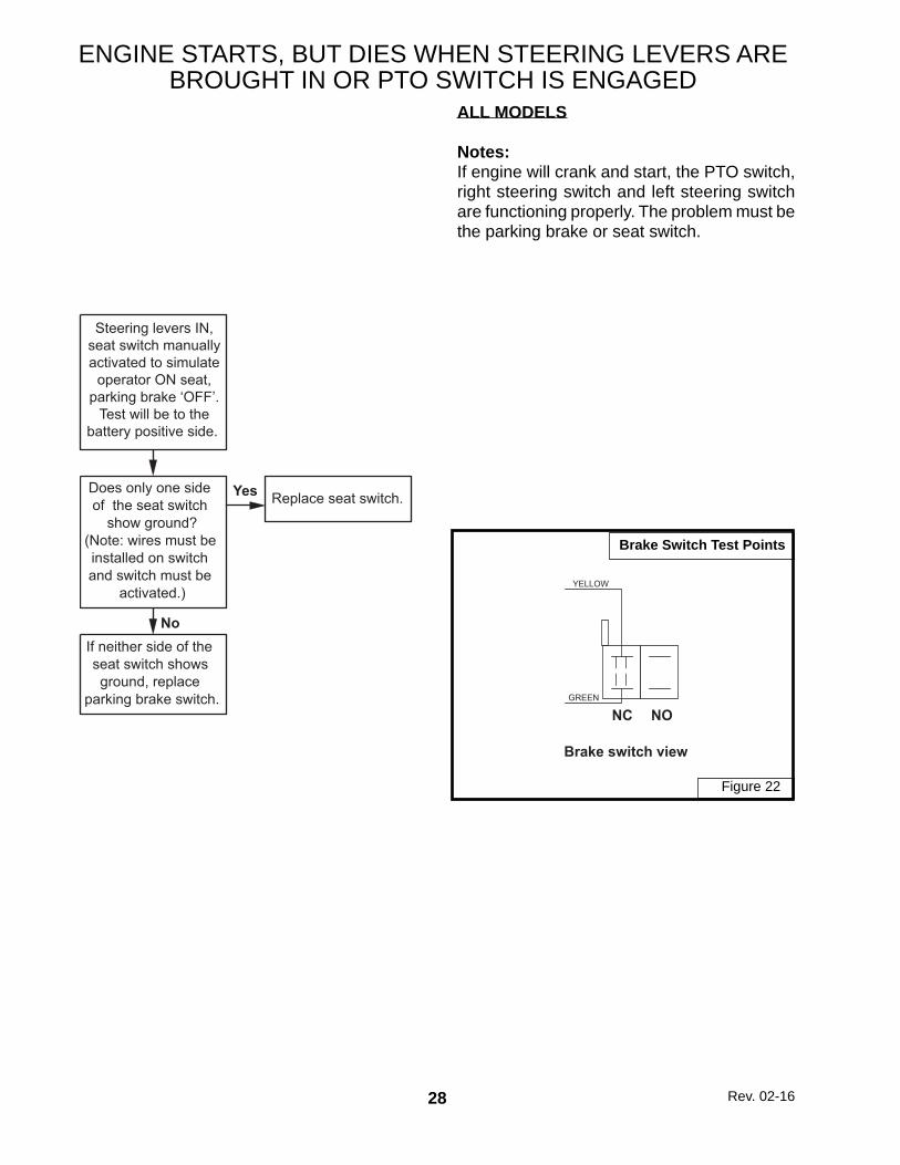
ENGINE STARTS, BUT DIES WHEN STEERING LEVERS ARE BROUGHT IN OR PTO SWITCH IS ENGAGED
ALL MODELS
Notes:If engine will crank and start, the PTO switch, right steering switch and left steering switch are functioning properly. The problem must be the parking brake or seat switch.
NC NO
YELLOW
GREEN
Brake switch view
Brake Switch Test Points
Figure 22
Rev. 02-16
Steering levers IN,seat switch manuallyactivated to simulate
operator ON seat,parking brake ‘OFF’.
Test will be to thebattery positive side.
If neither side of the seat switch shows ground, replace
parking brake switch.
Does only one side of the seat switch
show ground?(Note: wires must be installed on switch and switch must be
activated.)
No
Replace seat switch.Yes
29
THIS PAGE IS INTENTIONALLY LEFT BLANK
30
012,
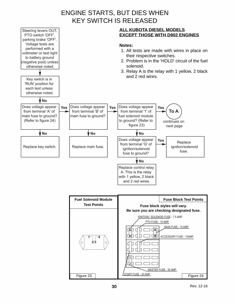
ALL KUBOTA DIESEL MODELSEXCEPT THOSE WITH D902 ENGINES
Notes: 1. All tests are made with wires in place on
their respective switches. 2. Problem is in the 'HOLD' circuit of the fuel
solenoid. 3. Relay A is the relay with 1 yellow, 2 black
and 2 red wires.
Fuse Block Test PointsFuel Solenoid ModuleTest Points
ENGINE STARTS, BUT DIES WHEN KEY SWITCH IS RELEASED
Fuse block styles will vary.Be sure you are checking designated fuse.
parking brake 'OFF'.Voltage tests areperformed with a
voltmeter or test lightto battery ground
(negative post) unless otherwise noted.
Replace key switch.
Does voltage appear from terminal 'A' of
main fuse to ground? (Refer to figure 24)
No
Yes
Key switch is in 'RUN' position for each test unless otherwise noted.
No
Replace main fuse.
Does voltage appear from terminal 'B' of
main fuse to ground?
No
Yes Does voltage appear from terminal '1' of
fuel solenoid module to ground? (Refer to
figure 23)
No
Yes
Does voltage appear from terminal 'G' of
ignition/solenoid fuse to ground?
No
Yes
Replace control relay A. This is the relay
with 1 yellow, 2 black and 2 red wires.
Replace ignition/solenoid
fuse.
To A
continues on next page
31
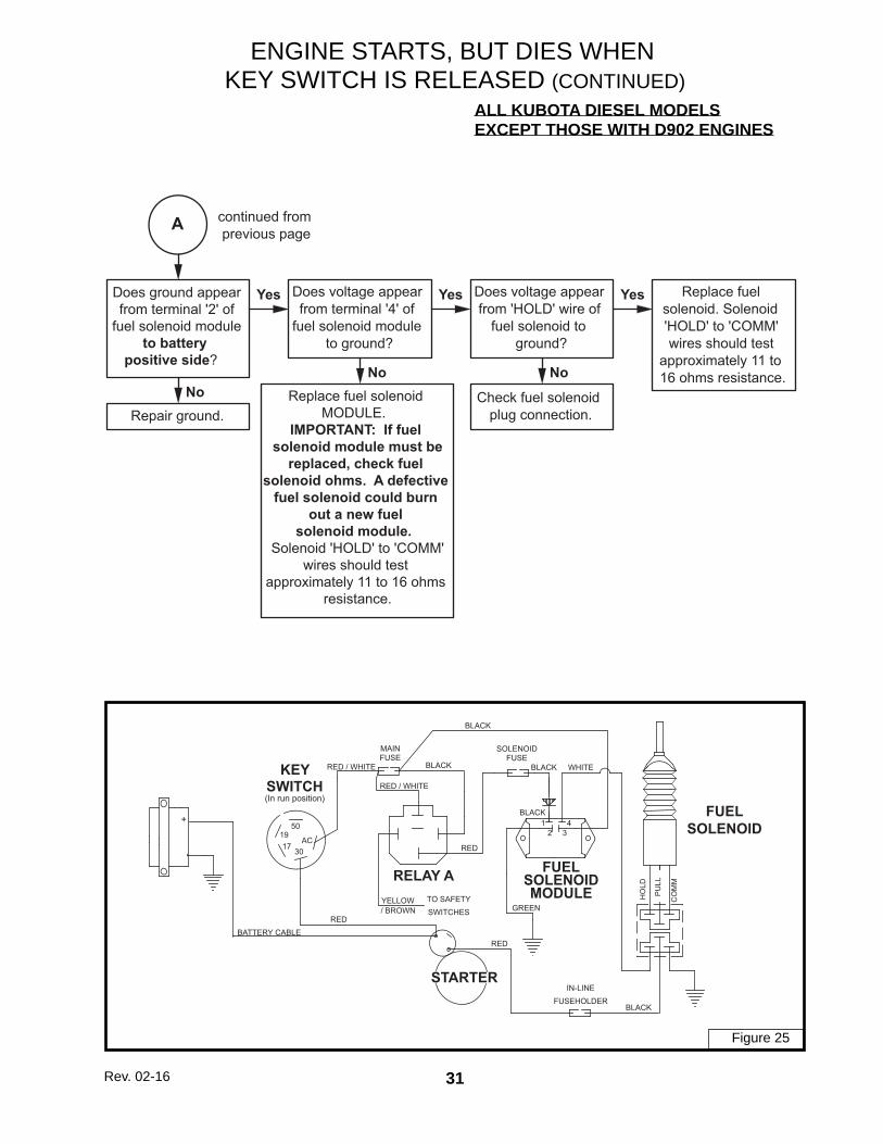
ALL KUBOTA DIESEL MODELSEXCEPT THOSE WITH D902 ENGINES
1
17 30
24
HO
LD
1950
AC
-
+3
CO
MMRELAY A
PU
LL
TO SAFETYSWITCHES
STARTER
BATTERY CABLE
FUELSOLENOID
FUELSOLENOIDMODULE
IN-LINEFUSEHOLDER
RED
KEYSWITCH(In run position)
RED / WHITE
RED / WHITE
RED
RED
BLACK
BLACK
BLACK
BLACK WHITE
BLACK
GREENYELLOW/ BROWN
MAINFUSE
SOLENOIDFUSE
ENGINE STARTS, BUT DIES WHENKEY SWITCH IS RELEASED (CONTINUED)
Figure 25
Rev. 02-16
A
Does ground appearfrom terminal '2' of
fuel solenoid moduleto battery
positive side?
No
Yes
Repair ground.
Does voltage appear from terminal '4' of
fuel solenoid module to ground?
No
Yes Does voltage appear from 'HOLD' wire of
fuel solenoid to ground?
No
Yes
Check fuel solenoid plug connection.
Replace fuel solenoid. Solenoid 'HOLD' to 'COMM' wires should test
approximately 11 to 16 ohms resistance.
continued from previous page
Replace fuel solenoid MODULE.
IMPORTANT: If fuel solenoid module must be
replaced, check fuel solenoid ohms. A defective
fuel solenoid could burn out a new fuel
solenoid module. Solenoid 'HOLD' to 'COMM'
wires should test approximately 11 to 16 ohms
resistance.
32
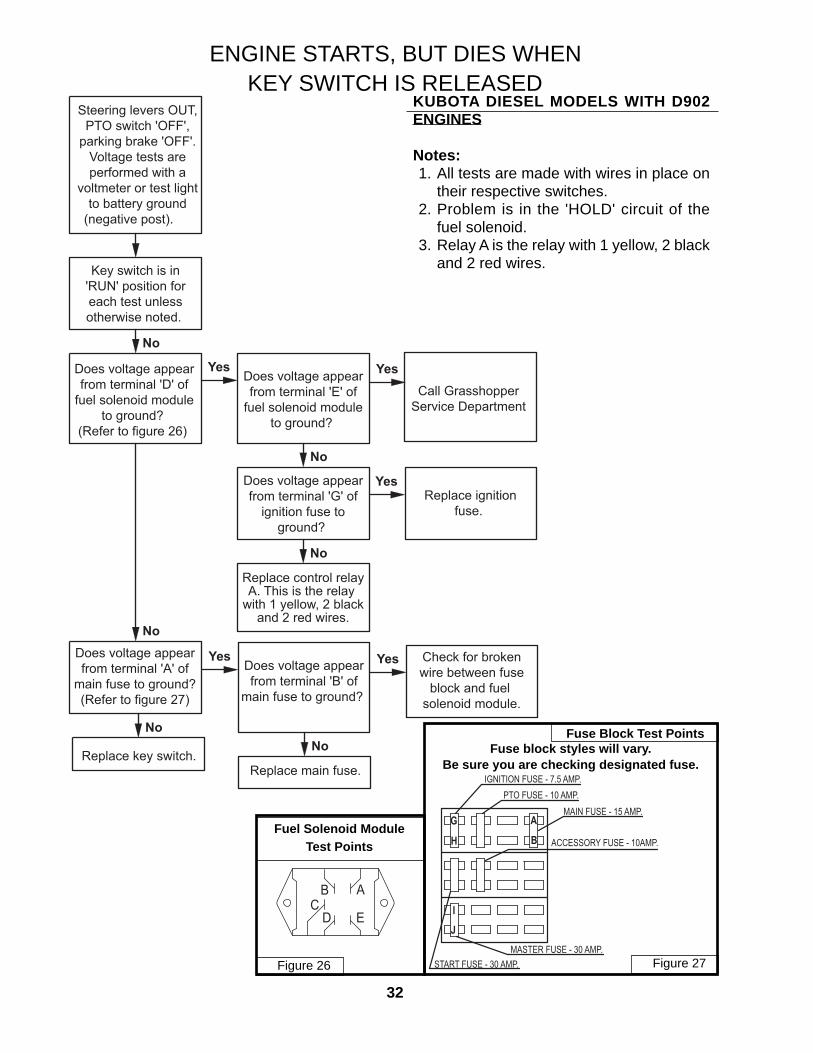
KUBOTA DIESEL MODELS WITH D902 ENGINES
Notes: 1. All tests are made with wires in place on
their respective switches. 2. Problem is in the 'HOLD' circuit of the
fuel solenoid. 3. Relay A is the relay with 1 yellow, 2 black
and 2 red wires.
Fuse Block Test Points
Fuel Solenoid ModuleTest Points
ABC
D E
Steering levers OUT,PTO switch 'OFF',
parking brake 'OFF'.Voltage tests areperformed with a
voltmeter or test lightto battery ground
(negative post).
Does voltage appearfrom terminal 'D' of
fuel solenoid moduleto ground?
(Refer to figure 26)
No
Yes
Key switch is in'RUN' position foreach test unlessotherwise noted.
No
Does voltage appearfrom terminal 'E' of
fuel solenoid moduleto ground?
No
Yes
Does voltage appearfrom terminal 'G' of
ignition fuse toground?
No
YesReplace ignition
fuse.
Does voltage appearfrom terminal 'A' of
main fuse to ground?(Refer to figure 27)
No
Replace key switch.
Replace control relayA. This is the relay
with 1 yellow, 2 blackand 2 red wires.
YesDoes voltage appearfrom terminal 'B' of
main fuse to ground?
No
Replace main fuse.
Yes Check for brokenwire between fuse
block and fuel solenoid module.
Call GrasshopperService Department
ENGINE STARTS, BUT DIES WHEN KEY SWITCH IS RELEASED
Fuse block styles will vary.Be sure you are checking designated fuse.
START FUSE - 30 AMP.
IGNITION FUSE - 7.5 AMP.PTO FUSE - 10 AMP.
MAIN FUSE - 15 AMP.
ACCESSORY FUSE - 10AMP.
MASTER FUSE - 30 AMP.
G
B
A
I
J
H
Figure 26 Figure 27
33
BRIGGS & KOHLERMODELSNotes: 1. If engine cranks and starts but dies when
key switch is released, then PTO switch, right and left steering switches, carbure-tor solenoid and stop relay are functioning properly.
2. Problem is a blown light/aux. fuse, a fuse block connection or a bad key switch.
3. All tests are made with wires in place on their respective switches.
Does voltage appearat top of
light/aux fuse to ground?
No
Does voltageappear from terminal
'L' of key switchto ground?
Yes Yes Problem is fuse
clip or wire to
carburetor solenoid.
Yes
No
Problem is light/auxfuse clip or wire from key switch to fuse.
Replace fuse.
Key switch is in'RUN' position for each test.
Steering levers out, PTO switch 'OFF'. Voltage tests are performed with a
voltmeter or test light to ground
(negative post).
No
Replace Key switch
Does voltage appearon bottom of
light/aux fuse to ground?
Yes
ENGINE STARTS, BUT DIES WHEN KEY SWITCH IS RELEASED
34
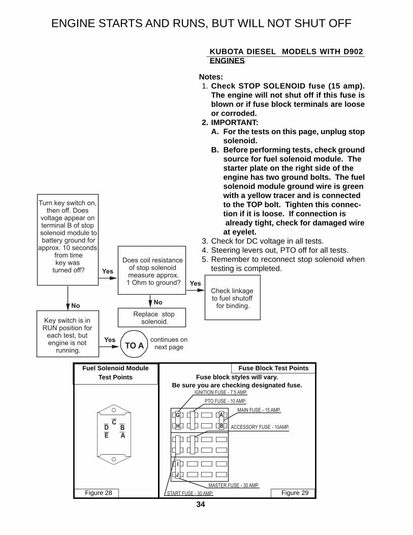
Yes continues onnext pageTO A
Turn key switch on, then off. Does
voltage appear on terminal B of stop solenoid module to battery ground for
approx. 10 seconds from timekey was
turned off?
Does coil resistance of stop solenoid measure approx.
1 Ohm to ground?
Replace stop solenoid.
Check linkage to fuel shutoff
for binding.
Key switch is in RUN position for
each test, but engine is not
running.
No
Yes
No
Yes
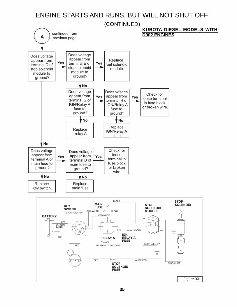
ENGINE STARTS AND RUNS, BUT WILL NOT SHUT OFF
KUBOTA DIESEL MODELS WITH D902 ENGINES
Fuse Block Test PointsFuel Solenoid ModuleTest Points
Notes: 1. Check STOP SOLENOID fuse (15 amp).
The engine will not shut off if this fuse is blown or if fuse block terminals are loose or corroded.
2. IMPORTANT: A. For the tests on this page, unplug stop solenoid. B. Before performing tests, check ground source for fuel solenoid module. The starter plate on the right side of the engine has two ground bolts. The fuel solenoid module ground wire is green with a yellow tracer and is connected to the TOP bolt. Tighten this connec-
tion if it is loose. If connection is already tight, check for damaged wire at eyelet. 3. Check for DC voltage in all tests. 4. Steering levers out, PTO off for all tests. 5. Remember to reconnect stop solenoid when
testing is completed.
CB
A
D
E
Fuse block styles will vary.Be sure you are checking designated fuse.
START FUSE - 30 AMP.
IGNITION FUSE - 7.5 AMP.PTO FUSE - 10 AMP.
MAIN FUSE - 15 AMP.
ACCESSORY FUSE - 10AMP.
MASTER FUSE - 30 AMP.
G
B
A
I
J
H
Figure 28 Figure 29
35
Yes
No
Yes
continued fromprevious pageA
No
No
Yes
Does voltage appear from terminal D of stop solenoid
module to ground?
Does voltage appear from terminal E of stop solenoid
module to ground?
Does voltage appear from terminal G of IGN/Relay A
fuse to ground?
Replace relay A
Does voltage appear from terminal H of IGN/Relay A
fuse to ground?
Replace IGN/Relay A
fuse
Check for loose terminal in fuse block
or broken wire.
Replace fuel solenoid
module
Does voltage appear from terminal A of main fuse to
ground?
Replace key switch.
Does voltage appear from terminal B of main fuse to
ground?
Replace main fuse.
Check for loose
terminal in fuse block or broken
wire.
Yes
No
No No
Yes Yes
IN RUN POSITION
BLACK
YELLOW
RED/WHITE
GREEN/YELLOW
RED
RED/WHITE
BATTERY
BLACK
BLACK
RELAY A
KEY
SWITCH
SOLENOID
RED
STOP
TO SAFETTY SWITCHES
MAIN
FUSE
FUSE
RELAY A
MODULE
SOLENOID
STOP
STOP
SOLENOID
FUSE
AE
D B
C
WHITE/RED
BLUE/WHITE
RED
RED
BATTERYCABLE
IGN/
KUBOTA DIESEL MODELS WITH D902 ENGINES
ENGINE STARTS AND RUNS, BUT WILL NOT SHUT OFF(CONTINUED)
Figure 30
36
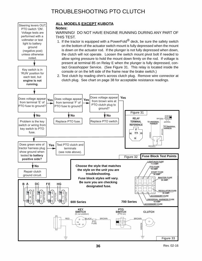
TROUBLESHOOTING PTO CLUTCH
ALL MODELS EXCEPT KUBOTANotes:WARNING! DO NOT HAVE ENGINE RUNNING DURING ANY PART OF THIS TEST. 1. If the tractor is equipped with a PowerFold® deck, be sure the safety switch
on the bottom of the actuator switch mount is fully depressed when the mount is down on the actuator rod. If the plunger is not fully depressed when down, the clutch will not operate. Loosen the switch mount pivot bolt if needed to allow spring pressure to hold the mount down fi rmly on the rod. If voltage is present at terminal 85 on Relay E when the plunger is fully depressed, con-tact Grasshopper Service. (See Figure 31. This relay is located inside the console or on the left side of the frame near the brake switch.)
2. Test clutch by reading ohm's across clutch plug. Remove wire connector at clutch plug. See chart on page 38 for acceptable resistance readings.
Fuse Block Test Points
ST
AR
T F
US
E
30
7.5
RE
GU
LA
TO
R F
US
E
LIG
HT
FU
SE
GHCDAB
10
PT
O F
US
E
EF
7.5
Choose the style that matchesthe style on the unit you are
troubleshooting.Fuse block styles will vary.Be sure you are checking
designated fuse.
30 AMP.REGULATOR FUSE
10 AMP.
LIGHT/AUX FUSE
30 AMP
7.5 AMP.PTO FUSE
START FUSE
UNIVERSAL HARNESS FUSE
30 AMP.MASTER FUSE
ACCESSORY FUSE
ACCESSORY FUSE10 AMP
Figure 32
Figure 33
MB
S
G
L
KEYSWITCH(In run position)
RED BLACK BROWN BROWN
GR
EE
N-
+
PTOSWITCH
(PTO on)CLUTCH
PTOFUSE
Figure 31
E
BROWN
BROWN
GR
EE
N
BR
OW
N
TO UNIVERSALHARNESS
TO UNIVERSALHARNESS
BROWN
8787A86 85
30
RELAYTERMINAL
REFERENCE
600 Series 700 Series
Rev. 02-16
No
Yes
No No
Yes
No
Yes
Yes
Steering levers OUT,PTO switch ‘ON’.Voltage tests areperformed with a voltmeter or test light to battery
ground(negative post)
unless otherwisenoted.
Key switch is in‘RUN’ position for
each test, butengine is not
running.
Does voltage appearfrom terminal ‘E’ of
PTO fuse to ground?
Does voltage appearfrom terminal ‘F’ of
PTO fuse to ground?
Does voltage appearfrom brown wire atPTO clutch plug to
ground?
Problem is the keyswitch or wiring fromkey switch to PTO
fuse.
Replace PTO fuse. Replace PTO switch.
Does green wire oftractor harness plugshow ground whentested to batterypositive side?
Test PTO clutch andterminals
(see note above).
Repair clutchground circuit.
37
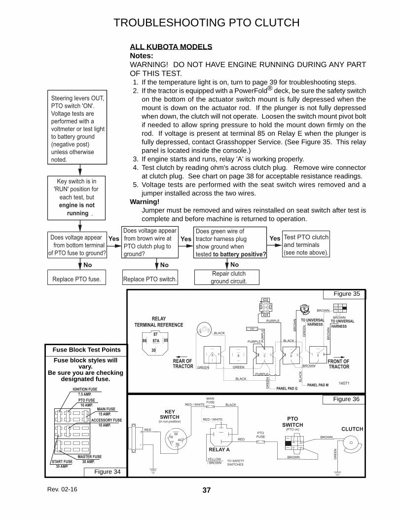
TROUBLESHOOTING PTO CLUTCH
ALL KUBOTA MODELSNotes:WARNING! DO NOT HAVE ENGINE RUNNING DURING ANY PART OF THIS TEST. 1. If the temperature light is on, turn to page 39 for troubleshooting steps. 2. If the tractor is equipped with a PowerFold® deck, be sure the safety switch
on the bottom of the actuator switch mount is fully depressed when the mount is down on the actuator rod. If the plunger is not fully depressed when down, the clutch will not operate. Loosen the switch mount pivot bolt if needed to allow spring pressure to hold the mount down fi rmly on the rod. If voltage is present at terminal 85 on Relay E when the plunger is fully depressed, contact Grasshopper Service. (See Figure 35. This relay panel is located inside the console.)
3. If engine starts and runs, relay 'A' is working properly. 4. Test clutch by reading ohm's across clutch plug. Remove wire connector
at clutch plug. See chart on page 38 for acceptable resistance readings. 5. Voltage tests are performed with the seat switch wires removed and a
jumper installed across the two wires.Warning! Jumper must be removed and wires reinstalled on seat switch after test is
complete and before machine is returned to operation.
Fuse Block Test Points
MAIN
FUSE
TO SAFETY
SWITCHES
SWITCH
RELAY A
(in run position)
BROWN
GR
EE
N
CLUTCH
PTO
SWITCH(PTO on)
PTOFUSE
BROWN
RED
YELLOW/ BROWN
RED / WHITE
RED / WHITE
BLACK
RED
50
AC
3017
19
KEY
Fuse block styles will vary.
Be sure you are checking designated fuse.
START FUSE30 AMP.
10 AMP.
7.5 AMP.
15 AMP.
IGNITION FUSE
PTO FUSE
MAIN FUSE
10 AMP.ACCESSORY FUSE
30 AMP.MASTER FUSE
Figure 36
Figure 34
Steering levers OUT,PTO switch 'ON'.Voltage tests areperformed with avoltmeter or test lightto battery ground(negative post)unless otherwisenoted.
Replace PTO fuse.
Does voltage appear from bottom terminal
of PTO fuse to ground?
No
Yes
Key switch is in 'RUN' position for
each test, but engine is not
running .
Replace PTO switch.
Does voltage appear from brown wire at PTO clutch plug to ground?
No
Yes
No
YesDoes green wire of tractor harness plug show ground when tested to battery positive?
Repair clutchground circuit.
Test PTO clutch and terminals (see note above).
Figure 35
DC E
4
5
3 6
2
1
TEMP.G I
BROWN
PU
RP
LEG
RE
EN
PANEL PAD M
PURPLE
BROWN
BR
OW
N
GR
EE
N
BR
OW
N
TO UNIVERSAL
BLACK
GREENGREEN
HARNESSTO UNIVERSALHARNESS
BLACK
BLA
CK
BLACK
PANEL PAD G
PURPLE
PURPLE
BROWN
14071
A B
REAR OF TRACTOR
FRONT OF TRACTOR
8787A86 85
30
RELAYTERMINAL REFERENCE
CLUTCH
Rev. 02-16
38
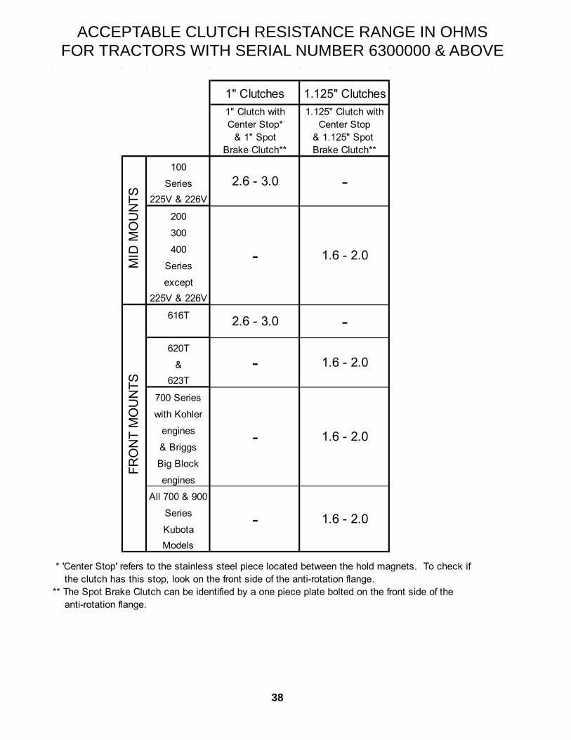
ACCEPTABLE CLUTCH RESISTANCE RANGE IN OHMSFOR TRACTORS WITH SERIAL NUMBER 6300000 & ABOVE
1" Clutches 1.125" Clutches1" Clutch with 1.125" Clutch withCenter Stop* Center Stop
* 'Center Stop' refers to the stainless steel piece located between the hold magnets. To check if the clutch has this stop, look on the front side of the anti-rotation flange.** The Spot Brake Clutch can be identified by a one piece plate bolted on the front side of the anti-rotation flange.
2.6 - 3.0
1.6 - 2.0
2.6 - 3.0 -
- 1.6 - 2.0
-
-
FRO
NT
MO
UN
TSM
ID M
OU
NTS
1.6 - 2.0
1.6 - 2.0 -
-
39
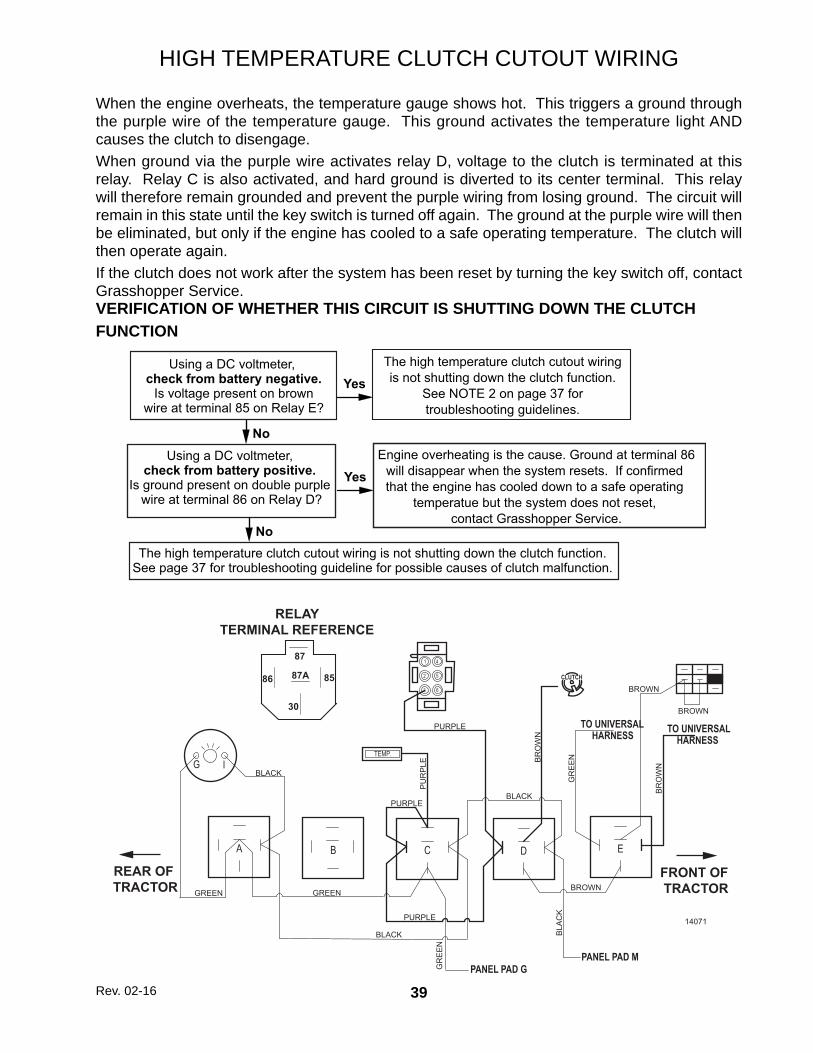
HIGH TEMPERATURE CLUTCH CUTOUT WIRING
When the engine overheats, the temperature gauge shows hot. This triggers a ground through the purple wire of the temperature gauge. This ground activates the temperature light AND causes the clutch to disengage.When ground via the purple wire activates relay D, voltage to the clutch is terminated at this relay. Relay C is also activated, and hard ground is diverted to its center terminal. This relay will therefore remain grounded and prevent the purple wiring from losing ground. The circuit will remain in this state until the key switch is turned off again. The ground at the purple wire will then be eliminated, but only if the engine has cooled to a safe operating temperature. The clutch will then operate again.If the clutch does not work after the system has been reset by turning the key switch off, contact Grasshopper Service.
DC E
4
5
3 6
2
1
TEMP.G I
BROWN
PU
RP
LE
GR
EE
N
PANEL PAD M
PURPLE
BROWN
BR
OW
N
GR
EE
N
BR
OW
N
TO UNIVERSAL
BLACK
GREENGREEN
HARNESS TO UNIVERSALHARNESS
BLACK
BLA
CK
BLACK
PANEL PAD G
PURPLE
PURPLE
BROWN
14071
A B
REAR OF TRACTOR
FRONT OF TRACTOR
87
87A86 85
30
RELAYTERMINAL REFERENCE
CLUTCH
VERIFICATION OF WHETHER THIS CIRCUIT IS SHUTTING DOWN THE CLUTCH FUNCTION
Rev. 02-16
Using a DC voltmeter, check from battery negative.
Is voltage present on brownwire at terminal 85 on Relay E?
Yes
Using a DC voltmeter, check from battery positive.
Is ground present on double purple wire at terminal 86 on Relay D?
The high temperature clutch cutout wiringis not shutting down the clutch function.
See NOTE 2 on page 37 fortroubleshooting guidelines.
No
Yes
The high temperature clutch cutout wiring is not shutting down the clutch function.See page 37 for troubleshooting guideline for possible causes of clutch malfunction.
Engine overheating is the cause. Ground at terminal 86will disappear when the system resets. If confirmed that the engine has cooled down to a safe operating
temperatue but the system does not reset, contact Grasshopper Service.
No
40
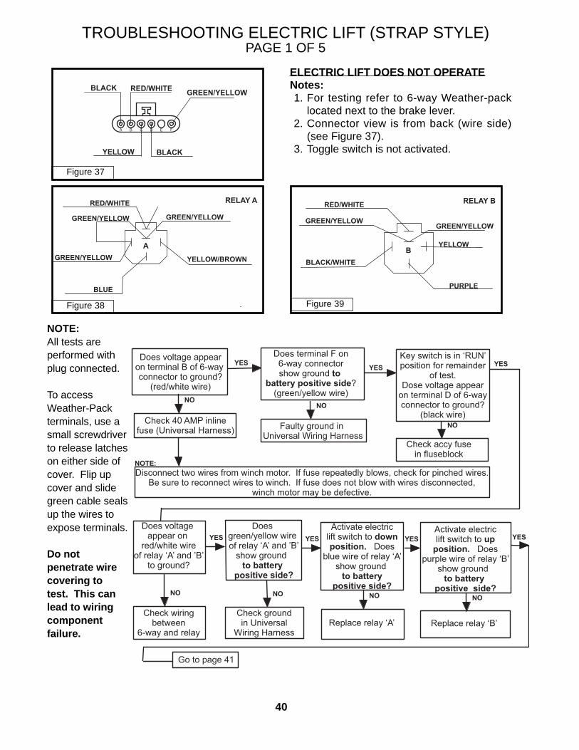
TROUBLESHOOTING ELECTRIC LIFT (STRAP STYLE)PAGE 1 OF 5
ELECTRIC LIFT DOES NOT OPERATENotes: 1. For testing refer to 6-way Weather-pack
located next to the brake lever. 2. Connector view is from back (wire side)
(see Figure 37). 3. Toggle switch is not activated.
Does voltage appearon terminal B of 6-way connector to ground?
(red/white wire)
NO
YESYESYES
NO
NOTE:
NO
NO NO NO
YES
NO
Does terminal F on6-way connectorshow ground to
battery positive side?(green/yellow wire)
Key switch is in ‘RUN’position for remainder
of test.Dose voltage appear
on terminal D of 6-wayconnector to ground?
(black wire)Check 40 AMP inline
fuse (Universal Harness) Faulty ground in Universal Wiring Harness
Check accy fusein fluseblock
Disconnect two wires from winch motor. If fuse repeatedly blows, check for pinched wires.Be sure to reconnect wires to winch. If fuse does not blow with wires disconnected,
winch motor may be defective.
Does voltage appear on
red/white wireof relay ‘A’ and ’B’
to ground?
Does green/yellow wire of relay ‘A’ and ’B’
show ground to battery
positive side?
Activate electriclift switch to downposition. Does
blue wire of relay ‘A’show ground
to batterypositive side?
YESActivate electriclift switch to up
position. Doespurple wire of relay ‘B’
show ground to battery
positive side?
YES YES
Check wiringbetween
6-way and relay
Check groundin Universal
Wiring HarnessReplace relay ‘A’ Replace relay ‘B’
Go to page 41
NOTE:All tests areperformed withplug connected.
To accessWeather-Packterminals, use asmall screwdriverto release latcheson either side ofcover. Flip upcover and slidegreen cable sealsup the wires to expose terminals.
Do notpenetrate wirecovering totest. This canlead to wiringcomponentfailure.
Figure 37
Figure 39Figure 38
GREEN/YELLOW
A B C D E F
BLACKYELLOW
RED/WHITEBLACK
GREEN/YELLOW
GREEN/YELLOW
BLUE
YELLOW/BROWN
RED/WHITERELAY A
GREEN/YELLOW
A
RED/WHITE
GREEN/YELLOW
RELAY B
GREEN/YELLOW
PURPLE
BLACK/WHITE
YELLOW B
41
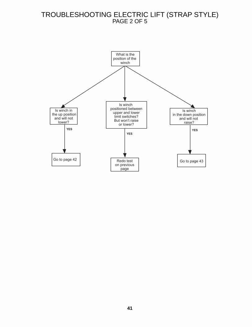
TROUBLESHOOTING ELECTRIC LIFT (STRAP STYLE)PAGE 2 OF 5
YESYES
YES
What is theposition of the
winch
Is winch in the up position
and will notlower?
Is winch positioned between
upper and lowerlimit switches?But won’t raise
or lower?
Is winchin the down position
and will not raise?
Go to page 42 Go to page 43Redo teston previous
page
42
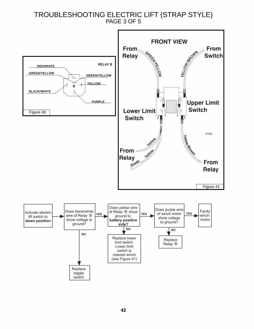
TROUBLESHOOTING ELECTRIC LIFT (STRAP STYLE)PAGE 3 OF 5
Figure 40
Figure 41
RED/WHITE
GREEN/YELLOW
RELAY B
GREEN/YELLOW
PURPLE
BLACK/WHITE
YELLOW B
97056
YESYESYES
NO
NO NO
Activate electriclift switch to
down position
Does black/whitewire of Relay ‘B’show voltage to
ground?
Does yellow wireof Relay ’B’ show
ground to battery positive
side?
Does purple wireof winch motorshow voltageto ground?
Faultywinch motor
Replacetoggleswitch
Replace lowerlimit switch.Lower limitswitch is
nearest winch(see Figure 41)
ReplaceRelay ‘B’
43
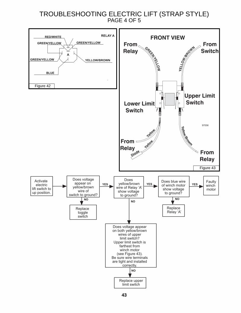
TROUBLESHOOTING ELECTRIC LIFT (STRAP STYLE)PAGE 4 OF 5
Figure 43
Figure 42
GREEN/YELLOW
GREEN/YELLOW
BLUE
YELLOW/BROWN
RED/WHITE RELAY A
GREEN/YELLOW
A
97056
NO
NONO NO
YESYESYESActivate electric
lift switch toup position.
Does voltageappear on
yellow/brownwire of
switch to ground?
Does yellow/brown
wire of Relay ‘A’show voltage
to ground?
Does blue wireof winch motorshow voltageto ground?
Faultywinch motor
Replace toggleswitch
Replace Relay ‘A’
Does voltage appearon both yellow/brown
wires of upperlimit switch?
Upper limit switch isfarthest fromwinch motor
(see Figure 43).Be sure wire terminalsare tight and installed
correctly.
Replace upperlimit switch
44
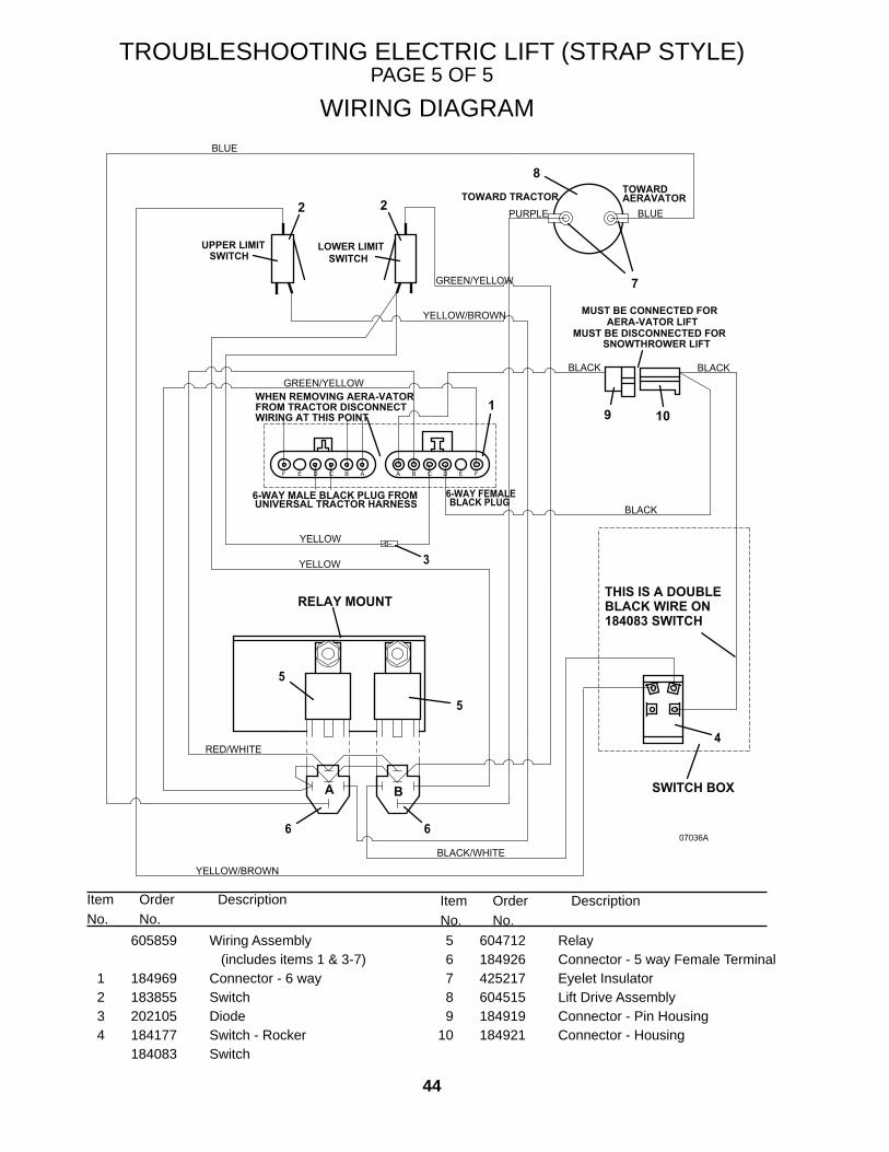
TROUBLESHOOTING ELECTRIC LIFT (STRAP STYLE)PAGE 5 OF 5
WHEN REMOVING AERA-VATOR FROM TRACTOR DISCONNECT WIRING AT THIS POINT
BLACK
MUST BE CONNECTED FORAERA-VATOR LIFT
07036A6
3
A B C D E FABCDEF
THIS IS A DOUBLE BLACK WIRE ON 184083 SWITCH
A B
45
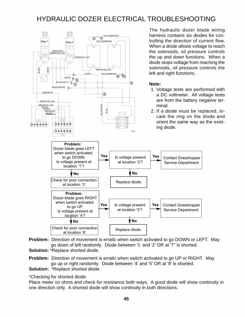
HYDRAULIC DOZER ELECTRICAL TROUBLESHOOTINGThe hydraulic dozer blade wiring harness contains six diodes for con-trolling the direction of current fl ow. When a diode allows voltage to reach the solenoids, oil pressure controls the up and down functions. When a diode stops voltage from reaching the solenoids, oil pressure controls the left and right functions.
Note: 1. Voltage tests are performed with
a DC voltmeter. All voltage tests are from the battery negative ter-minal.
2. If a diode must be replaced, lo-cate the ring on the diode and orient the same way as the exist-ing diode.
Problem: Direction of movement is erratic when switch activated to go DOWN or LEFT. May go down of left randomly. Diode between '1' and '2' OR at '7" is shorted.
Solution: *Replace shorted diode.
Problem: Direction of movement is erratic when switch activated to go UP or RIGHT. May go up or right randomly. Diode between '4' and '5' OR at '8' is shorted.
Solution: *Replace shorted diode.
*Checking for shorted diode:Place meter on ohms and check for resistance both ways. A good diode will show continuity in one direction only. A shorted diode will show continuity in both directions.
Check for poor connection at location ‘3’. Replace diode.
Is voltage presentat location ‘2’?
NoNo
Contact GrasshopperService Department.
Problem: Dozer blade goes RIGHT
when switch activated to go UP.
Is voltage present atlocation ‘4’?
YesYes
Check for poor connection at location ‘6’.
Replace diode.
Is voltage presentat location ‘5’?
NoNo
Contact GrasshopperService Department.
11101
FE
FEDCBA
DA B CF E D C B A
A B
CD
YELLOW/BROWN
RED/WHITEGREEN/YELLOW
YELLOW/BROWN
GREEN/YELLOW
RED/WHITE
GREEN/YELLOW
YELLOW/BROWN
GREEN/YELLOW
GREEN/YELLOWGREEN
BLACKRED/WHITE
BLACK
BLU
E/W
HIT
E
BLU
E
WHITE
WHITE
BLACK/WHITE
BLA
CK
WH
ITE
BLACK/WHITE
Relay 1 Relay 212
7
6
54
38
46
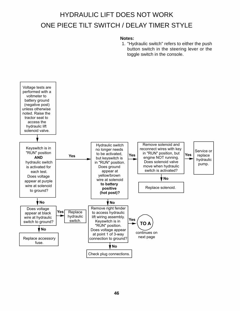
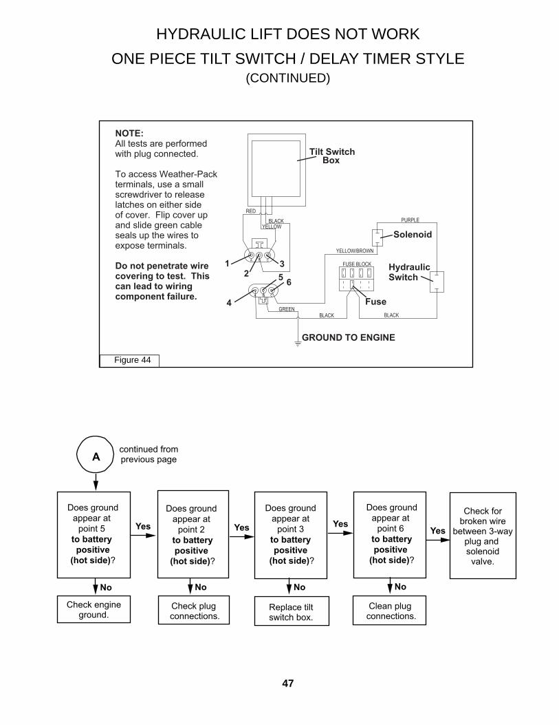
HYDRAULIC LIFT DOES NOT WORKONE PIECE TILT SWITCH / DELAY TIMER STYLE
Notes: 1. "Hydraulic switch" refers to either the push
button switch in the steering lever or the toggle switch in the console.
Voltage tests areperformed with a
voltmeter to battery ground(negative post)
unless otherwise noted. Raise the
tractor seat to access the
hydraulic lift solenoid valve.
Yes
No
Yes
Hydraulic switchno longer needs to be activated, but keyswitch is
in "RUN" position.Does ground
appear atyellow/brown
wire at solenoidto battery positive
(hot post)?
Keyswitch is in "RUN" position
AND hydraulic switchis activated for
each test.Does voltage
appear at purple wire at solenoid
to ground?
Does voltage appear at black wire at hydraulic switch to ground?
Replace accessoryfuse.
Yes
Remove right fenderto access hydrauliclift wiring assembly.
Keyswitch is in "RUN" position.
Does voltage appearat point 1 of 3-way
connection to ground?
Check plug connections.
No
No
NoNo
continues onnext page
TO A
Remove solenoid andreconnect wires with key
in "RUN" position, butengine NOT running.Does solenoid valvemove when hydraulicswitch is activated?
Service orreplace
hydraulicpump.
Replace solenoid.
Yes
Replacehydraulicswitch.
Yes
47
Yes
Does groundappear at
point 5 to battery positive
(hot side)?
Check engineground.
No
Yes
continued fromprevious pageA
Does ground appear at
point 2 to battery positive
(hot side)?
Does ground appear at
point 3 to battery positive
(hot side)?
Does groundappear at
point 6 to battery positive
(hot side)?
Check plug connections.
Replace tiltswitch box.
No No
Yes
Clean plug connections.
No
Yes
Check forbroken wire
between 3-wayplug and solenoid
valve.
HYDRAULIC LIFT DOES NOT WORK ONE PIECE TILT SWITCH / DELAY TIMER STYLE
(CONTINUED)
Figure 44
BoxTilt Switch
GREEN
BLACK BLACK
PURPLE
GROUND TO ENGINE
FUSE BLOCK
YELLOW/BROWN
CA B
CBA
BLACK
RED
YELLOW
Solenoid
Fuse
1
2
3
4
56
Hydraulic
Switch
NOTE:
All tests are performedwith plug connected.
To access Weather-Packterminals, use a smallscrewdriver to releaselatches on either sideof cover. Flip cover upand slide green cableseals up the wires toexpose terminals.
Do not penetrate wire
covering to test. This
can lead to wiring
component failure.
48
JOYSTICK WIRING TROUBLESHOOTINGTOTAL LOSS OF MOTION
Notes:Check battery voltage. Battery voltage should read a minimum of 12.5 DC volts.All tests are performed with key in the run position, steering levers out and PTO switch off.All tests are with a DC voltmeter from battery negative unless otherwise noted.
Disconnect the 6-way weather-pack connector next to the brake lever on the left side of the frame. Test is performed on the tractor side 6-way.
Yes
Does voltageappear at
red/white wireat terminal B?
Check 40 amp inline fuse wire from positive battery cable
terminal of starter.
No
Yes Does voltageappear at black wire
at terminal D?
Does ground appear at
green/yellow wireat terminal Ffrom battery
positive?
Check either the Universal WiringHarness fuse or
Accessory fuse in the fuse block.*
Check ground wire connection
at engine.
No No
Yes
Contact GrasshopperService Department
*There may be more than one Accessory fuse.If so, check all Accessory fuses.
TOENGINE
GROUND
BLACK
BROWN
MALE TERMINALS
6 WAY WEATHER-PACK
RED/WHITE
GREEN/YELLOW
CONNECTOR
40
CONNECTS TO ACCESSORY OR UWH FUSE IN FUSE BLOCK
CONNECTS TO POSITIVE BATTERY CABLE TERMINAL OF STARTER
D E FA CB
UNIVERSAL WIRING HARNESSOR
LIMITED UNIVERSAL HARNESS
49
JOYSTICK WIRING TROUBLESHOOTINGLOSS OF MOTION IN ONE DIRECTION
Notes:The following troubleshooting guidelines assume all directions except one function properly.This assumes the required voltage is reaching all relays, including the malfunctioning relay.All tests are performed with key in the run position, steering levers out and PTO switch off.Access the 4 relays inside the relay box for these tests.Use a DC voltmeter and check from battery positive.
BLACK
GR
EE
N
GREENGREEN GREEN
BLACK
RED
RED/ WHITE
RED/WHITE RED/WHITE RED/WHITE
BLACK
BLACKBLACK
BLA
CK
/WH
ITE
WH
ITE
BLU
E
BLU
E/W
HIT
E
GREEN
GREEN
GREEN
D
To Wiring Assembly 605973
COM
NO
NC
COM
NO
NC
COM
NO
NC
COM
NO
NC
B A
C D
To Universal Wiring Harness orLimited Universal Harness
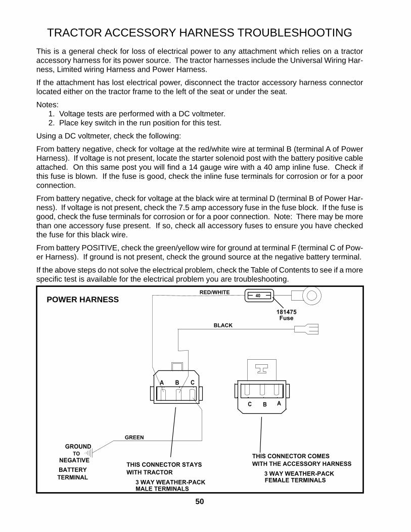
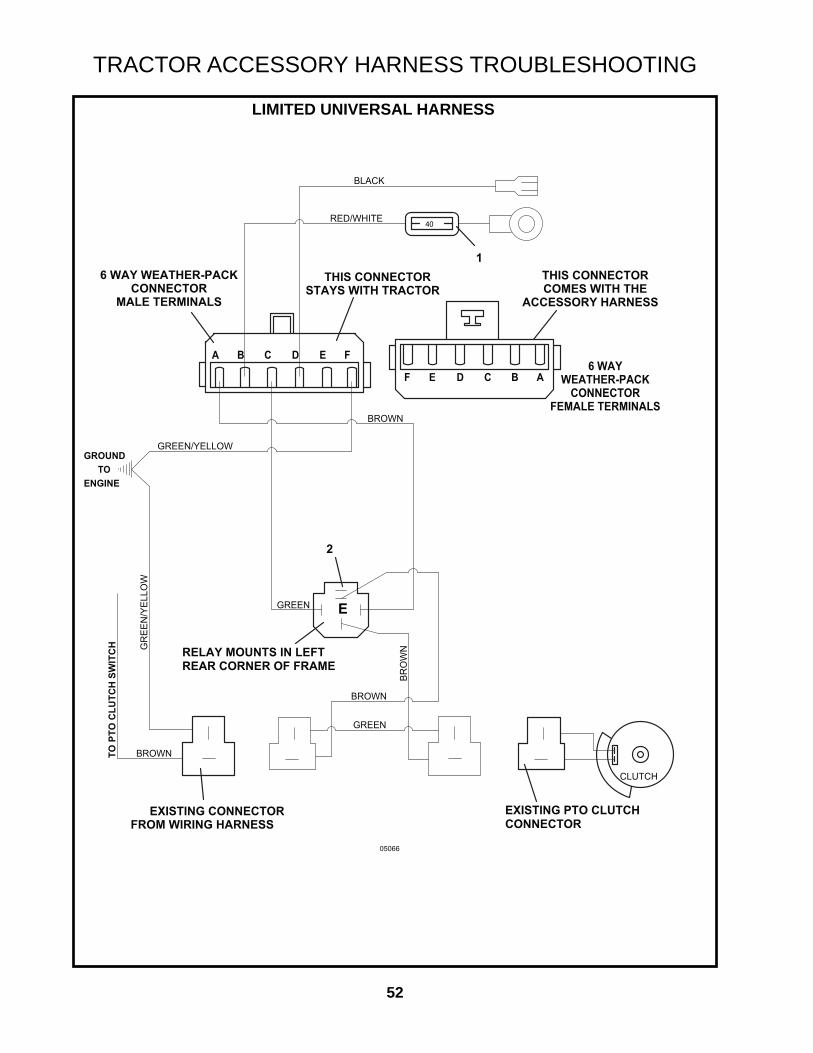
TRACTOR ACCESSORY HARNESS TROUBLESHOOTINGThis is a general check for loss of electrical power to any attachment which relies on a tractor accessory harness for its power source. The tractor harnesses include the Universal Wiring Har-ness, Limited wiring Harness and Power Harness.
If the attachment has lost electrical power, disconnect the tractor accessory harness connector located either on the tractor frame to the left of the seat or under the seat.
Notes: 1. Voltage tests are performed with a DC voltmeter. 2. Place key switch in the run position for this test.
Using a DC voltmeter, check the following:
From battery negative, check for voltage at the red/white wire at terminal B (terminal A of Power Harness). If voltage is not present, locate the starter solenoid post with the battery positive cable attached. On this same post you will fi nd a 14 gauge wire with a 40 amp inline fuse. Check if this fuse is blown. If the fuse is good, check the inline fuse terminals for corrosion or for a poor connection.
From battery negative, check for voltage at the black wire at terminal D (terminal B of Power Har-ness). If voltage is not present, check the 7.5 amp accessory fuse in the fuse block. If the fuse is good, check the fuse terminals for corrosion or for a poor connection. Note: There may be more than one accessory fuse present. If so, check all accessory fuses to ensure you have checked the fuse for this black wire.
From battery POSITIVE, check the green/yellow wire for ground at terminal F (terminal C of Pow-er Harness). If ground is not present, check the ground source at the negative battery terminal.
If the above steps do not solve the electrical problem, check the Table of Contents to see if a more specifi c test is available for the electrical problem you are troubleshooting.
POWER HARNESS181475Fuse
GREEN
THIS CONNECTOR STAYS WITH TRACTOR
RED/WHITE
3 WAY WEATHER-PACK 3 WAY WEATHER-PACK
BLACK
WITH THE ACCESSORY HARNESS
GROUNDTHIS CONNECTOR COMES TO
NEGATIVE
MALE TERMINALS FEMALE TERMINALS
BATTERY TERMINAL
40
B
B A
CA
C
51
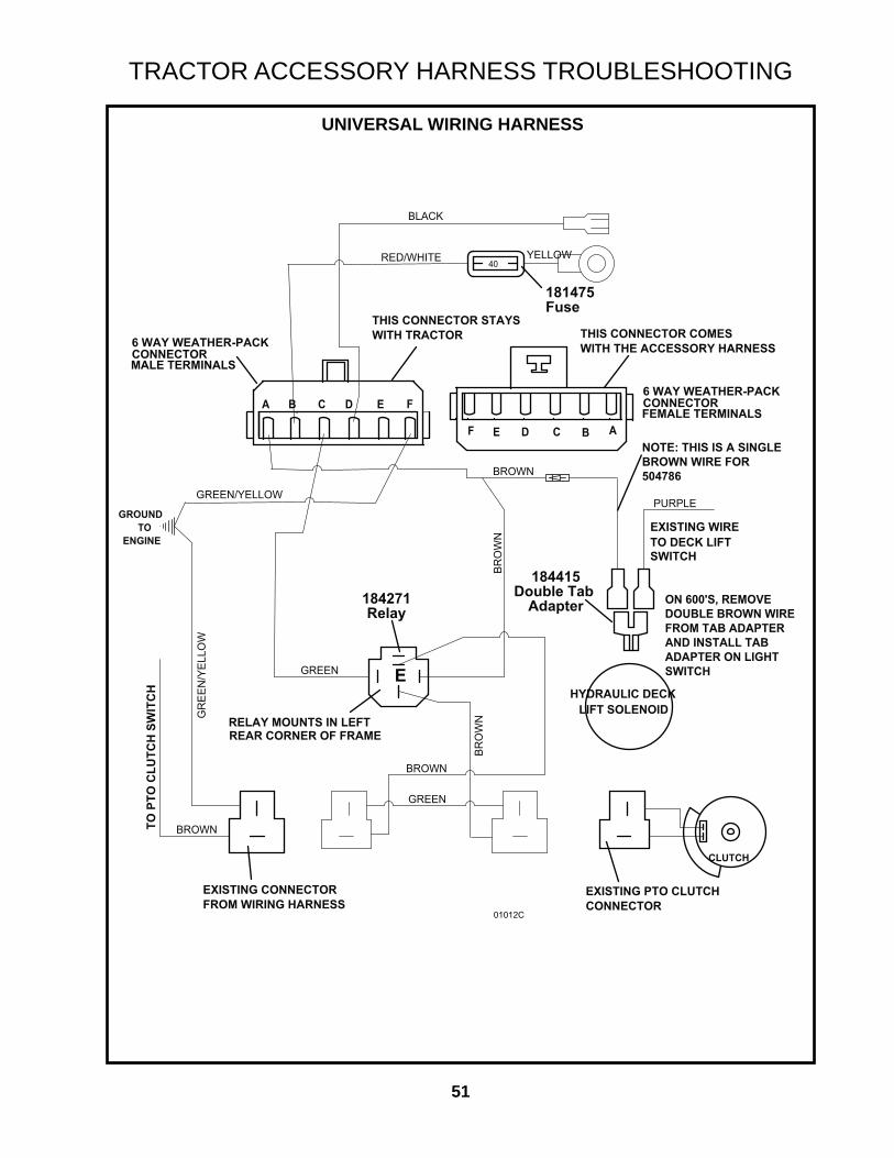
UNIVERSAL WIRING HARNESS
184415Double Tab
Adapter
181475Fuse
184271Relay
THIS CONNECTOR STAYS WITH TRACTOR
BROWN
TO P
TO C
LUTC
H S
WIT
CH
WITH THE ACCESSORY HARNESS
CONNECTOR EXISTING PTO CLUTCH
FROM WIRING HARNESS EXISTING CONNECTOR
TOENGINE
GROUND
GREEN
THIS CONNECTOR COMES
PURPLE
GR
EEN
/YEL
LOW
REAR CORNER OF FRAME RELAY MOUNTS IN LEFT
BLACK
GREEN
BROWN
BRO
WN
MALE TERMINALS
6 WAY WEATHER-PACK
HYDRAULIC DECK LIFT SOLENOID
EXISTING WIRE TO DECK LIFT SWITCH
BRO
WN
ON 600'S, REMOVEDOUBLE BROWN WIREFROM TAB ADAPTER AND INSTALL TAB ADAPTER ON LIGHT SWITCH


![INTRODUCTION TO GRASSHOPPER - Amazon S3s3.amazonaws.com/mcneel/grasshopper/Grasshopper_Intro_Outline.pdf · Introduction to Grasshopper-[GH-01] INTRODUCTION TO GRASSHOPPER Block 5-Day](https://static.documents.pub/doc/80x56/5ada38217f8b9a137f8d3089/introduction-to-grasshopper-amazon-s3s3-to-grasshopper-gh-01-introduction-to.jpg)

![Introduction and Intermediate - Grasshopper-[GH-102]files.mcneel.com/grasshopper/GH_2_Day_7_Hours.pdf · Introduction and Intermediate - Grasshopper-[GH-102] Target Audience This](https://static.documents.pub/doc/80x56/5ee07629ad6a402d666ba3d5/introduction-and-intermediate-grasshopper-gh-102files-introduction-and-intermediate.jpg)


