22
ELECTRICITY AND MAGNETISM

ELECTRICITY AND MAGNETISM
Electric Circuits
Lesson 1: Internal Resistance
Electric Circuit
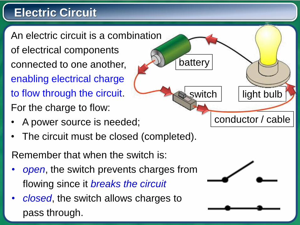
An electric circuit is a combination
of electrical components
connected to one another,
enabling electrical charge
to flow through the circuit.
For the charge to flow:
• A power source is needed;
• The circuit must be closed (completed).
light bulb
conductor / cable
switch
battery
Remember that when the switch is:
• open, the switch prevents charges from
flowing since it breaks the circuit
• closed, the switch allows charges to
pass through.
Unit of Charge
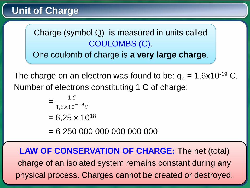
Charge (symbol Q) is measured in units called
COULOMBS (C).
One coulomb of charge is a very large charge.
The charge on an electron was found to be: qe = 1,6x10⁻¹⁹ C.
Number of electrons constituting 1 C of charge:
= 6,25 x 1018
= 6 250 000 000 000 000 000
LAW OF CONSERVATION OF CHARGE: The net (total)
charge of an isolated system remains constant during any
physical process. Charges cannot be created or destroyed.
Current
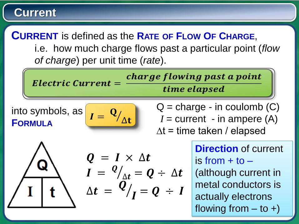
CURRENT is defined as the RATE OF FLOW OF CHARGE,
i.e. how much charge flows past a particular point (flow
of charge) per unit time (rate).
into symbols, as
FORMULA
Q = charge - in coulomb (C)
I = current - in ampere (A)
∆t = time taken / elapsed
Direction of current
is from + to –
(although current in
metal conductors is
actually electrons
flowing from – to +)
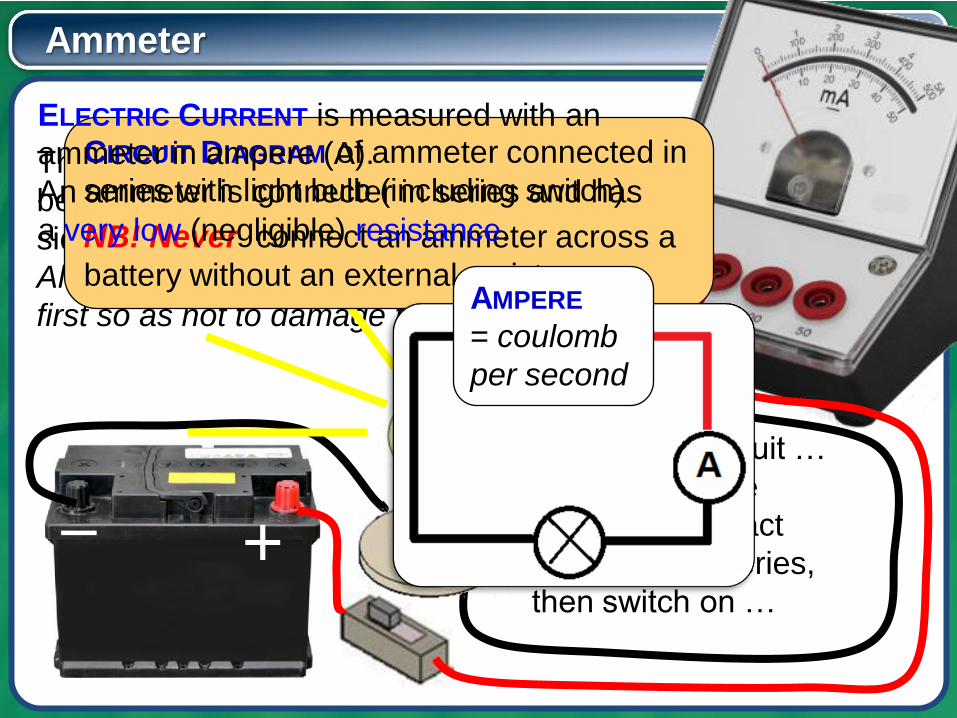
Ammeter
+–
The positive side of the meter (red) must
be connected closest to the positive
side of the battery.
Always connect to the largest scale
first so as not to damage the meter.
Complete the circuit …
Confirm that the
ammeter is in fact
connected in series,
then switch on …
CIRCUIT DIAGRAM of ammeter connected in
series with light bulb (including switch).
NB! Never connect an ammeter across a
battery without an external resistance.AMPERE
= coulomb
per second
ELECTRIC CURRENT is measured with an
ammeter in ampere (A).
An ammeter is connecter in series and has
a very low (negligible) resistance.
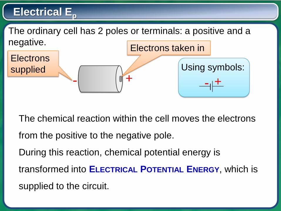
Electrical Ep
The ordinary cell has 2 poles or terminals: a positive and a
negative.
+-
Electrons taken inElectrons
supplied
The chemical reaction within the cell moves the electrons
from the positive to the negative pole.
During this reaction, chemical potential energy is
transformed into ELECTRICAL POTENTIAL ENERGY, which is
supplied to the circuit.
+-
Using symbols:
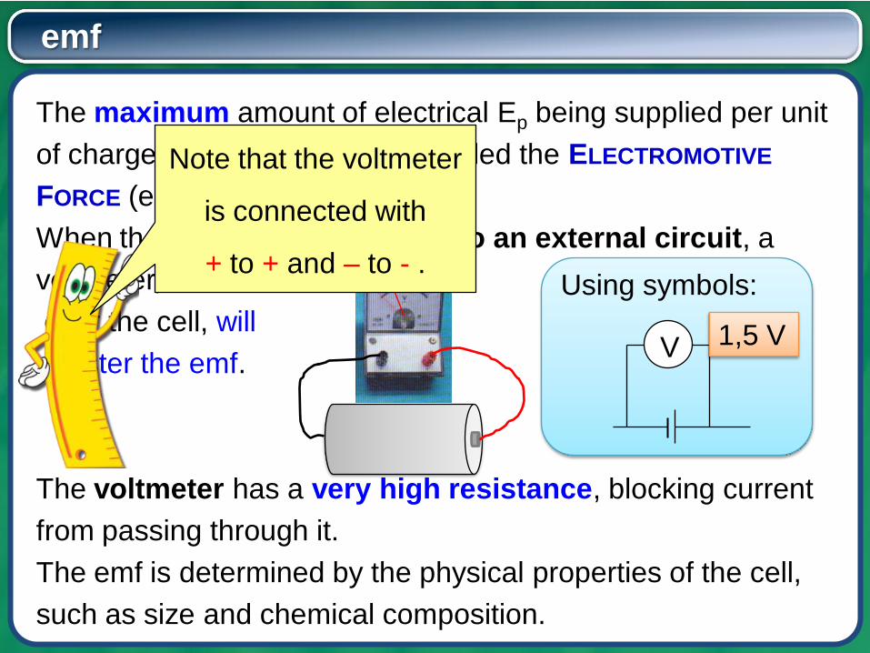
emf
The maximum amount of electrical Ep being supplied per unit
of charge moved by the cell, is called the ELECTROMOTIVE
FORCE (emf) of the cell.
When the cell is not connected to an external circuit, a
voltmeter, connected
over the cell, will
register the emf.
The voltmeter has a very high resistance, blocking current
from passing through it.
The emf is determined by the physical properties of the cell,
such as size and chemical composition.
V
Using symbols:
1,5 V
Note that the voltmeter
is connected with
+ to + and – to - .
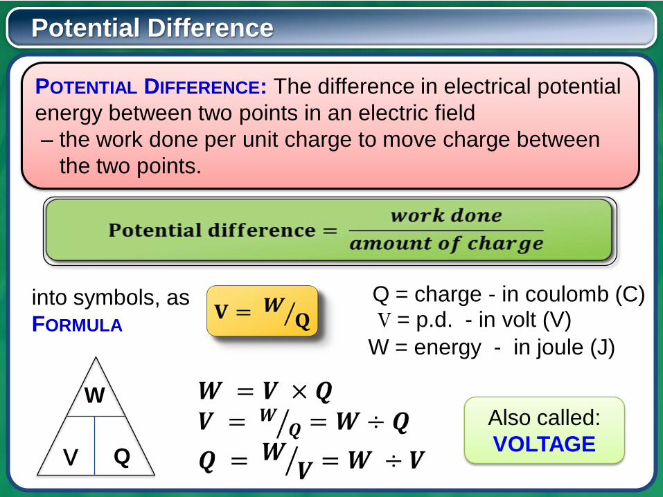
Potential Difference
POTENTIAL DIFFERENCE: The difference in electrical potential
energy between two points in an electric field
– the work done per unit charge to move charge between
the two points.
into symbols, as
FORMULA
Q = charge - in coulomb (C)V = p.d. - in volt (V)
W = energy - in joule (J)
Q
W
V
Also called:
VOLTAGE
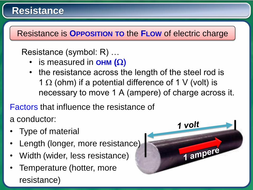
Resistance (symbol: R) …
• is measured in OHM (Ω)
• the resistance across the length of the steel rod is
1 Ω (ohm) if a potential difference of 1 V (volt) is
necessary to move 1 A (ampere) of charge across it.
Resistance
Resistance is OPPOSITION TO the FLOW of electric charge
Factors that influence the resistance of
a conductor:
• Type of material
• Length (longer, more resistance)
• Width (wider, less resistance)
• Temperature (hotter, more
resistance)

ELECTRICITY AND MAGNETISM
Class Exercise 1/1
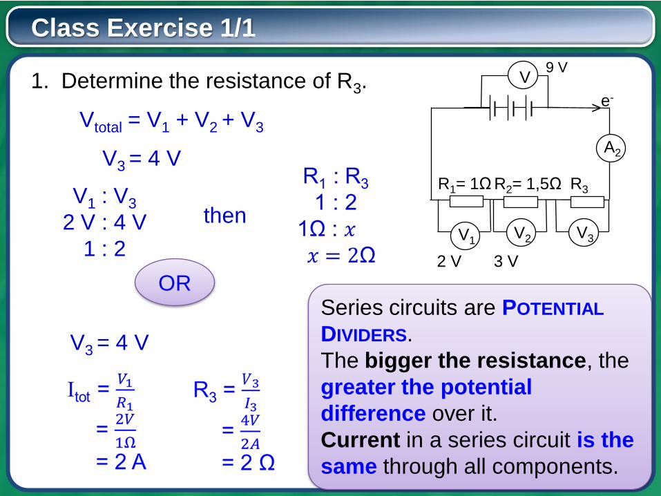
1. Determine the resistance of R3.V
A2
>
9 V
V2 V3V1
R1= 1Ω R2= 1,5Ω R3
2 V 3 V
V3 = 4 V
Vtotal = V1 + V2 + V3
V1 : V3
2 V : 4 V
1 : 2
then
ORSeries circuits are POTENTIAL
DIVIDERS.
The bigger the resistance, the
greater the potential
difference over it.
Current in a series circuit is the
same through all components.
V3 = 4 V
e-
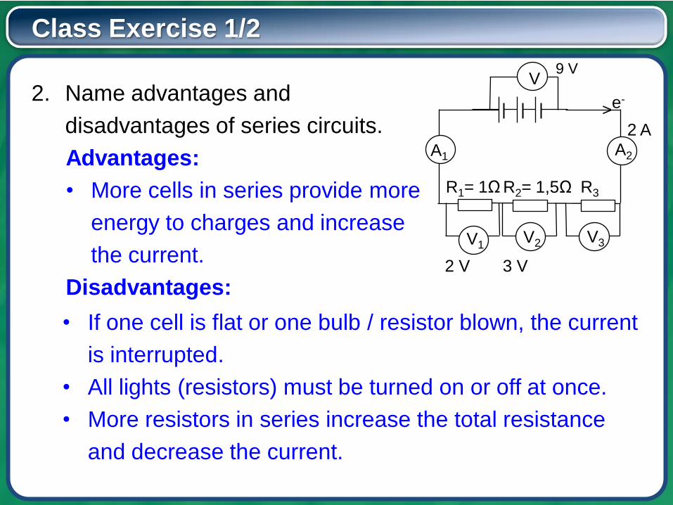
Class Exercise 1/2
2. Name advantages and
disadvantages of series circuits.
Advantages:
• More cells in series provide more
energy to charges and increase
the current.
Disadvantages:
V
A2
>
9 V
V2 V3V1
R1= 1Ω R2= 1,5Ω R3
2 V 3 V
e-
• If one cell is flat or one bulb / resistor blown, the current
is interrupted.
• All lights (resistors) must be turned on or off at once.
• More resistors in series increase the total resistance
and decrease the current.
A1
2 A
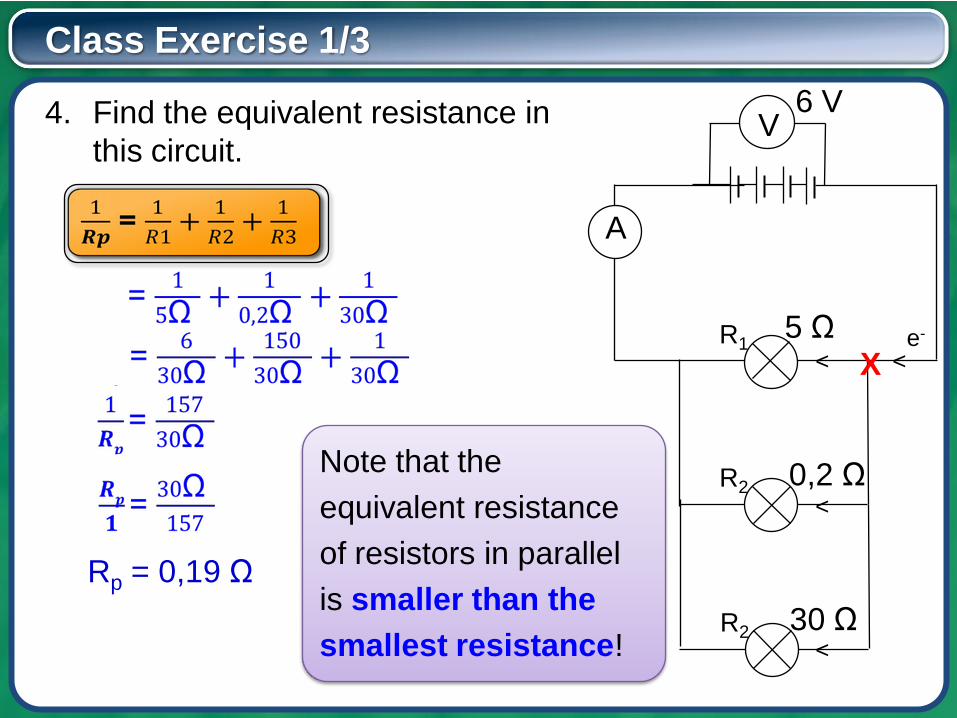
Class Exercise 1/3
4. Find the equivalent resistance in
this circuit.V
A
R1<
e-
<
R2
6 V
5 ΩX
0,2 Ω
R2 30 Ω
<
<
Rp = 0,19 Ω
Note that the
equivalent resistance
of resistors in parallel
is smaller than the
smallest resistance!
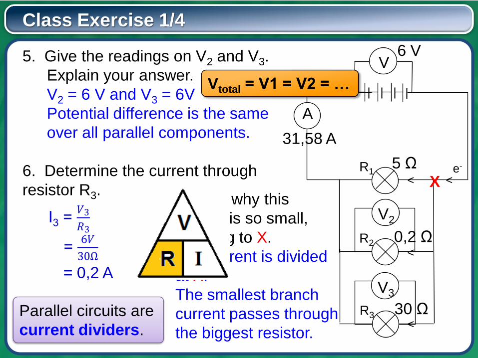
Class Exercise 1/4
5. Give the readings on V2 and V3.
Explain your answer.
V2 = 6 V and V3 = 6V
Potential difference is the same
over all parallel components.
6. Determine the current through
resistor R3.
V
A
R1<
e-
<
R2
6 V
5 ΩX
0,2 Ω
R3 30 Ω
<
<
V3
V2
= 0,2 A
Vtotal = V1 = V2 = …
7. Explain why this
current is so small,
referring to X.
The current is divided
at X.
The smallest branch
current passes through
the biggest resistor.
31,58 A
Parallel circuits are
current dividers.
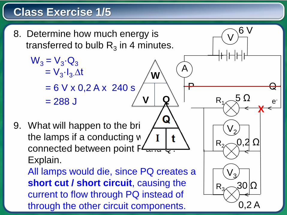
Class Exercise 1/5
8. Determine how much energy is
transferred to bulb R3 in 4 minutes.V
A
R1<
e-
<
R2
6 V
5 ΩX
0,2 Ω
R3 30 Ω
<
<
V3
V2
W3 = V3·Q3
= V3·I3·∆t
= 6 V x 0,2 A x 240 s
= 288 J
0,2 A
9. What will happen to the brightness of
the lamps if a conducting wire is
connected between point P and Q?
Explain.
All lamps would die, since PQ creates a
short cut / short circuit, causing the
current to flow through PQ instead of
through the other circuit components.
∙ P Q ∙
Q
W
V
Class Exercise 1/6
10. Give advantages and disadvantages of parallel circuits.
Advantages:
• The equivalent resistance of parallel resistors is smaller
than the smallest individual resistance and therefore
increases the current.
• If a cell is flat or a resistor / bulb is blown, the current can
still continue.
• Lights (resistors) can be turned on or off individually.
• Cells in parallel last longer, since each cell only have to
supply a part of the charges with energy.
Disadvantage:
• Cells in parallel do not provide the unit charge with more
energy.
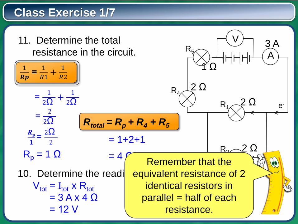
Class Exercise 1/7
V
A
R1<
e-
<
R2
3 A
2 Ω
2 Ω<Rp = 1 Ω
R42 Ω
R5
11. Determine the total
resistance in the circuit.
Rtotal = Rp + R4 + R5
= 1+2+1
1 Ω
= 4 Ω
10. Determine the reading on V.
Vtot = Itot x Rtot
= 3 A x 4 Ω
= 12 V
Remember that the
equivalent resistance of 2
identical resistors in
parallel = half of each
resistance.
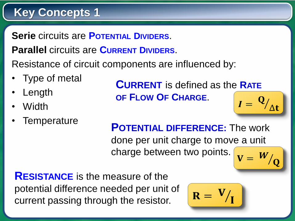
Key Concepts 1
Serie circuits are POTENTIAL DIVIDERS.
Parallel circuits are CURRENT DIVIDERS.
Resistance of circuit components are influenced by:
• Type of metal
• Length
• Width
• Temperature
CURRENT is defined as the RATE
OF FLOW OF CHARGE.
POTENTIAL DIFFERENCE: The work
done per unit charge to move a unit
charge between two points.
RESISTANCE is the measure of the
potential difference needed per unit of
current passing through the resistor.
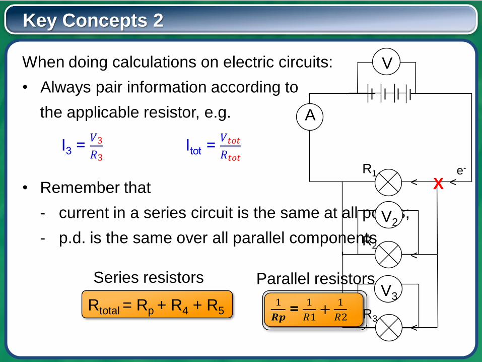
Key Concepts 2
When doing calculations on electric circuits:
• Always pair information according to
the applicable resistor, e.g.
• Remember that
- current in a series circuit is the same at all points;
- p.d. is the same over all parallel components
V
A
R1<
e-
<
R2
X
R3
<
<
V3
V2
Rtotal = Rp + R4 + R5
Series resistors Parallel resistors
• Memorise the various definitions
• Review the exercises you had difficulty with …
• and do some additional exercise …
• as given in your workbooks that accompany this
video series or from your school textbook
Continue your learning by watching the
next video lesson in this series:
Lesson 2: Internal Resistance

inishe


