34
WHAT MOVES YOUR WORLD ELECTRO-HYDRAULIC VALVES – A TECHNICAL LOOK

WHAT MOVES YOUR WORLD
ELECTRO-HYDRAULIC VALVES – A TECHNICAL LOOK

2
MOOG VALVE TYPES EXPLAINED Moog Electro-hydraulic Valves
Whenever the highest levels of motion control performance and design flexibility are required, you’ll find Moog expertise at work.
Moog is a registered trademark of Moog Inc. and its subsidiaries. All trademarks as indicated herein are the property of Moog Inc. and its subsidiaries. For the full disclaimer refer to www.moog.com/literature/disclaimers.
For the most current information, visit www.moog.com/industrial or contact your local Moog office.
INTRODUCTION ........................................................................................................................................................................................ 2
About Moog, Applications, Assistance ................................................................................................................................... 3
MOOG VALVE TYPES EXPLAINED .................................................................................................................................................. 5-9
Servo and Proportional Valves .................................................................................................................................................. 5
Directly and Pilot Operated Valves ......................................................................................................................................... 6
Electrical and Mechanical Feedback Valves ........................................................................................................................ 7
EFB Valves with Analog or Digital Electronics .................................................................................................................. 8
Pressure and Flow Control and Axis Control Valves ..................................................................................................... 9
OPERATING PRINCIPLES ...................................................................................................................................................................... 10-15
Nozzle Flapper Operated Valves ............................................................................................................................................... 11-12
Servo Operated Valves .................................................................................................................................................................. 13
Linear Force Motor Operated Valves ..................................................................................................................................... 14-15
VALVE SIZING ........................................................................................................................................................................................... 16-21
PRACTICAL CONSIDERATIONS WHEN LAYING OUT EH CONTROL SYSTEMS ......................................................... 22-29
Position, Velocity and Pressure/Force Control Circuits ................................................................................................. 23-24
General Electro-hydraulic System Layout ............................................................................................................................. 25-29
ROUTINE MAINTENANCE .................................................................................................................................................................... 30-33

3
MOOG VALVE TYPES EXPLAINED Moog Electro-hydraulic Valves
ELEcTRO-HYDRAULic VALVES – A TEcHnicAL LOOk
About this Guide
We have been producing electro-hydraulic servo valves since 1951. Since then, our experts have had countless discus-sions with our customers about their applications and how to use our valves to achieve the best performance for their applications. We have written this guide to deal with topics that are essential for making the best use of our valves.
We will start by explaining the basics about our different valve types, which include servo valves, proportional valves, EFB valves and MFB valves, and we’ll also describe the functional principles of the typical Moog valves. We will then give guidance about selecting and sizing the optimal valve for your application. After that, we will offer some practical consi-derations for laying out electro-hydraulic control systems. Finally, we will provide some thoughts on system and valve maintenance to make sure your Moog Valves have a long service.
Applications
Moog Servo and Proportional Valves are found across a wide range of markets and applications. From metal forming, wood processing and plastics machinery to test and simulation equipment and offshore and marine applications, whenever high-performance control is needed, you will find Moog Valves.
For example, Moog Valves accurately control the thickness of sheet steel in steel mills as well as paper in paper mills. They control all major and many minor functions in plastic injection molding machines. They also control the stability of offshore oil drilling platforms in rough and hazardous conditions and the fuel injection process in marine diesel engines.
Each of these applications involves precise control of a complex structure, which in most cases is subject to varying loads that can adversely affect performance. Moog products overcome the structural and load variation effects through the principles of feedback. Moog transducers measure an output, which includes position, velocity, pressure or acceleration, and send signals to the machine controller. These signals are then compared with the desired output. The sensing and corresponding correction on a continuous basis results in optimum system performance.
Assistance
The information in this brochure represents typical products offered by Moog; our expertise is helping you solve your motion control problems. Our sales and engineering experts will assist you in your efforts to accurately and precisely con-trol position, velocity or force in your specific application. Often times this results in developing a customized design and product, specifically suited to your need. Our capabilities in this respect are unmatched in the industry. Contact us and let us know how we can help.
Since we are continually improving our products through research and development, we will from time to time change speci-fications in this catalog without notice. Please contact us prior to making any calculations or purchased based on this guide.

4
Moog Electro-hydraulic Valves
MOOG VALVE TYPES EXPLAinED
MOOG VALVE TYPES EXPLAINED
Some basic information about Moog Servo and Proportional Valves and their different features.

5
MOOG VALVE TYPES EXPLAINED Moog Electro-hydraulic Valves
MOOG VALVE TYPES EXPLAinED
Moog produces many different valve types to suit the different applications of our customers. If you ever asked yourself what the difference between a servo and a proportional valve is, what an MFB or an EFB valve is or what a pQ valve or ACV can do, then you should read this chapter.
Servo and Proportional Valves
Servo valves are usually perceived as high-end valves that are used to get the maximum performance out of your machine, while proportional valves are seen as all-round valves used for basic applications. The main difference between a servo and a proportional valve is the spool overlap in the center position. While a servo valve has a spool overlap of <3% of the spool stroke, a proportional valve has an overlap of 3% or more (as defined in ISO 5598).
This usually leads to servo valves being built with a spool that is sliding inside a hardened steel bushing, while proporti-onal valves have the spool sliding directly inside the cast iron valve housing (Moog also builds proportional valves with a bushing spool assembly). The layout and the main characteristics of both valves is shown below.
Spool sliding in hardened steel bushing
XX YT A P T1B
Spool sliding in valve housing
XX YT A P T1B
Features
• Bushing-spool (BSA) design• Spool overlap < ±1%• Very high pressure gain• Very high accuracy and dynamics• Rated flow specified at 70 bar (1,000 psi)
pressure drop
Moog Servo Valves
Moog Proportional Valves
Features
• Spool-in-Body (SiB) design• Spool overlap ± 3% or more• Lower accuracy and dynamics than servo valves• Higher rated flows than servo valves• Nominal flow specified at 10 bar (150 psi)
pressure drop

6
MOOG VALVE TYPES EXPLAINED Moog Electro-hydraulic Valves
MOOG VALVE TYPES EXPLAinED
TVBVPVAV
X YT A P B
Directly and Pilot Operated Valves
Directly operated valves are valves where the spool is mechanically attached to the actuator and directly moved by it. To limit the size and cost of these actuators, the operating forces have to be limited. Since the forces necessary to move a spool are increasing with flow and pressure drop, directly operated valves are usually limited to smaller flows and thus smaller valve sizes. Moog Directly Operated Valves are mostly driven by a Linear Force Motor and called Direct Drive Valves (DDV).To increase the spool actuation force, the main spool of pilot operated valves is operated hydraulically by a pilot valve. By hydraulically amplifying the electrical command signal, pilot operated valves can reach very high spool actuation forces and thus be built up to very large rated flows. The pilot valve is usually a smaller, directly operated valve that is specially designed to be used as a pilot valve. Moog usually uses nozzle flapper, jetpipe or direct drive spool pilot valves. Sometimes, even two-stage pilot operated valves are used as pilot valves to increase performance.
Features
• Actuated by Linear Force Motor (LFM) with push-pull operation
• Low internal leakage losses• Low energy consumption in center position• Dynamics mostly independent from supply pressure• Higher forces than proportional solenoids, thus higher
pressure drops possible
Features
• Pilot principles: • Nozzle flapper • ServoJet∏
• Direct Drive Valve• High flow rates• Available as servo and proportional valves• Available with mechanical or electrical feedback
PT A YB
Moog Direct Drive (DDV) Valves
Moog Pilot Operated Valves

7
MOOG VALVE TYPES EXPLAINED Moog Electro-hydraulic Valves
MOOG VALVE TYPES EXPLAinED
Electrical and Mechanical Feedback Valves
All Moog Servo and Proportional Valves are equipped with a closed loop spool position control and thus require a spool position feedback. Moog uses two different types of feedback: Mechanical and electrical feedback. Mechanical feedback (MFB) valves include a feedback spring that is tensed by the spool deflection and gives a mechanical feedback to the torque motor. These valves do not need onboard electronics to operate. Electrical feedback (EFB) valves use an electronic position transducer to measure the spool position. This signal is fed back electrically, and thus all EFB valves need control electronics to operate. Moog Valves usually have this electronics integrated into the valve design and require no external controller cards.
Features
• “Classic” servo valve design• Nozzle flapper pilot• No onboard electronics• Closed loop position control of the spool by
mechanical feedback wire
Features
• Directly or pilot operated• ServoJet∏ or Linear Force Motor operated• Onboard electronics for closed loop position control
of the spool• Analog or digital electronics available• Optional fieldbus interfaces• Flow, pressure or axis control options
X T A PB
Moog Mechanical Feedback (MFB) Valves
Moog Electrical Feedback (EFB) Valves
PT A YB
8
MOOG VALVE TYPES EXPLAINED Moog Electro-hydraulic Valves
MOOG VALVE TYPES EXPLAinED
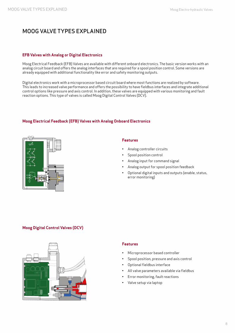
EFB Valves with Analog or Digital Electronics
Moog Electrical Feedback (EFB) Valves are available with different onboard electronics. The basic version works with an analog circuit board and offers the analog interfaces that are required for a spool position control. Some versions are already equipped with additional functionality like error and safety monitoring outputs.
Digital electronics work with a microprocessor based circuit board where most functions are realized by software. This leads to increased valve performance and offers the possibility to have fieldbus interfaces and integrate additional control options like pressure and axis control. In addition, these valves are equipped with various monitoring and fault reaction options. This type of valves is called Moog Digital Control Valves (DCV).
Features
• Analog controller circuits • Spool position control• Analog input for command signal• Analog output for spool position feedback• Optional digital inputs and outputs (enable, status,
error monitoring)
Features
• Microprocessor based controller• Spool position, pressure and axis control• Optional fieldbus interface• All valve parameters available via fieldbus• Error monitoring, fault reactions• Valve setup via laptop
Moog Electrical Feedback (EFB) Valves with Analog Onboard Electronics
Moog Digital Control Valves (DCV)
PT A YB

9
MOOG VALVE TYPES EXPLAINED Moog Electro-hydraulic Valves
MOOG VALVE TYPES EXPLAinED
Pressure and Flow Control and Axis Control Valves
Moog Digital Control Valves (DCV) are also available with extended control functionality. They offer pressure and flow control (pQ) or axis control (ACV). pQ valves are equipped with a spool position controller and can also control the pressure of one axis. This can, for example, be used for a positioning function with force limitation. Axis control valves can autono-mously control one axis, for example a cylinder, and perform position, speed or force control for this axis.
Features
• Integrated pressure transducer in port A• Operating modes: • Flow control • Pressure control • Flow and pressure control • Differential pressure control via external
pressure transducers
Features
• Interfaces for analog or digital transducers: • Analog inputs • SSI input • Encoder input • Strain gauge input • Fieldbus transducers• Position, speed or force control for one axis
Moog Pressure and Flow Control (pQ) Valves
Moog Axis Control Valves (ACV)
Integrated pressure transducer in port A
Transducer inputs
10
OPERATING PRINCIPLES Moog Electro-hydraulic Valves
OPERATinG PRinciPLES
Short overview of operating principles of Moog Valves.
11
OPERATING PRINCIPLES Moog Electro-hydraulic Valves
nOZZLE FLAPPER OPERATED VALVES
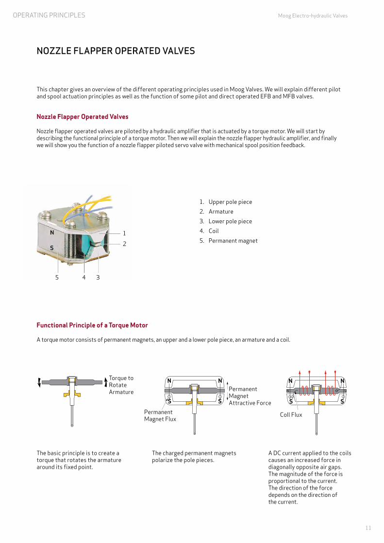
The basic principle is to create a torque that rotates the armature around its fixed point.
This chapter gives an overview of the different operating principles used in Moog Valves. We will explain different pilot and spool actuation principles as well as the function of some pilot and direct operated EFB and MFB valves.
Nozzle Flapper Operated Valves
Nozzle flapper operated valves are piloted by a hydraulic amplifier that is actuated by a torque motor. We will start by describing the functional principle of a torque motor. Then we will explain the nozzle flapper hydraulic amplifier, and finally we will show you the function of a nozzle flapper piloted servo valve with mechanical spool position feedback.
1. Upper pole piece2. Armature3. Lower pole piece4. Coil5. Permanent magnet
S
NNN
SS
NN
SS
1
2
3S
NNN
SS
NN
SS
1
2
3 S
NNN
SS
NN
SS
1
2
3
Torque to Rotate Armature
Permanent Magnet Flux
Permanent Magnet Attractive Force
Coll Flux
12
345
The charged permanent magnets polarize the pole pieces.
A DC current applied to the coils causes an increased force in diagonally opposite air gaps. The magnitude of the force is proportional to the current. The direction of the force depends on the direction of the current.
Functional Principle of a Torque Motor
A torque motor consists of permanent magnets, an upper and a lower pole piece, an armature and a coil.

12
OPERATING PRINCIPLES Moog Electro-hydraulic Valves
nOZZLE FLAPPER OPERATED VALVES
Functional Principle of a Nozzle Flapper Hydraulic Amplifier
• The armature and the flapper are rigidly joined and supported by a thin-wall flexure sleeve, which also acts as a centering spring for the torque motor.
• The fluid continuously flows from the pressure side PS, through both inlet orifices, past the two nozzles into the nozzle flapper space, and then through the drain orifice to tank.
• A rotary motion of the armature/flapper throttles the flow through one nozzle or the other. This diverts flow to one end of the spool.
1Ps Ps
T
2 3
4 1. Inlet orifice2. Flexure sleeve3. Flapper4. Armature
Nozzle Flapper Piloted Valve with Mechanical Feedback
• These valves contain a closed loop control circuit to control the position of the spool. Since the feedback of the spool position is transmitted via a mechanical feedback spring, they are often referred to as mechanical feedback valves (MFB valves).
• An electrical current in the torque motor coils creates magnetic forces on the ends of the armature. Thus, the arma-ture and flapper assembly rotates about a fixed point.
• The flapper closes off one nozzle and provides for an increase in pressure in that flow path. The pressure increase acts on the end of the spool causing the spool to move and opens PS to control port A. At the same time it also opens control port B to T.
• The spool pushes the ball end of the feedback spring creating a restoring torque on the armature/flapper.• As the feedback torque becomes equal to the torque from the magnetic forces, the armature/flapper moves back to
its centered position. At that time the spool stops at a position where the feedback spring torque equals the torque due to the input current. Therefore, the spool position is proportional to the input current. With constant pressures and loads, the flow to the actuator is proportional to the spool position.
PL
TT
BA
S S
N NSN
PsPs
Ps Ps
Valve responding to change in electrical input
Flow to Actuator
TT
BA
S S
N NSN
PsPs
Ps Ps
Valve condition following change

13
OPERATING PRINCIPLES Moog Electro-hydraulic Valves
SERVOJET OPERATED VALVES
ServoJet∏ Piloted Valve with Electrical Feedback
ServoJet∏ piloted Moog Valves are exclusively built as electrical feedback valves (EFB valves). This means that the valve’s internal spool position control loop is closed by an electronic controller and a position transducer. And onboard electronics (analog or microcontroller based) control the current to the torque motor coils.
• An electrical command signal corresponding to the desired spool position is applied to the integrated electronics, which drives the valve coil.
• The current through the coil displaces the jet pipe from its neutral position.• The displacement of the jet directs the flow to one end of the spool thereby increasing the driving force on the end of
the spool.• The spool moves and opens P to one control port, while the other control port is open to tank.• The position transducer (LVDT), which is excited via an oscillator, measures the position of the main spool (actual
position voltage).• The signal for the actual position of the spool is then demodulated and fed back to the controller, where it is
compared with the command signal.• The controller drives the pilot valve until the error between command signal and spool position feedback signal is zero.• Thus, the position of the main spool is proportional to the electrical command signal.
XX YT A P T1BXX YT A P T1B
Functional Principle of the ServoJet Hydraulic Amplifier
• The ServoJet∏ pilot stage consists mainly of a torque motor, a jet pipe, and a receiver.• A current through the coil displaces the jet pipe from its neutral position. This displacement, combined with the spe-
cial shape of the nozzle, directs a focused fluid jet on both receivers towards one receiver. This produces a pressure differential in the control chambers to the end of the spool.
• This pressure difference causes the spool to move. • The pilot stage drain is through the annular area around the nozzle to tank.
1
2
3
4
1. Annular area2. Nozzle3. Jet pipe4. Receiver
D661 valve in center position D661 valve in open position P B

14
OPERATING PRINCIPLES Moog Electro-hydraulic Valves
LinEAR FORcE MOTOR OPERATED VALVES
• Without a current being applied to the coil, the magnets and springs hold the armature at equilibrium.
• When a current is applied to the coil with one polarity, the flux in one of the air gaps surrounding the magnets is increased, cancelling out the flux in the other.
• This unequilibrium allows the armature to move in the direction of the stronger magnetic flux.
• The armature is moved in the opposite direction by changing the polarity of the current in the coil.
Functional Principle of the Linear Force Motor
Moog Direct Drive Valves (DDV) use our proprietary Linear Force Motor. A Linear Force Motor is a permanent magnet differential motor. The permanent magnets provide part of the required magnetic force. The Linear Force Motor has a neutral mid-position from which it generates force and stroke in both directions. This is an advantage against a propor-tional solenoid drive, which can only operate in one direction. Force and stroke of the Linear Force Motor are proportional to the applied current.
High spring stiffness and the resulting centering force, plus external forces (i.e., flow forces, friction forces due to contamination), must be overcome during outstroking. During backstroking to center position, the spring force adds to the motor force and provides additional spool driving force making the valve less contamination sensitive. The Linear Force Motor requires very low current in the spring centered position.
Moog Direct Drive Valves are usually built as electrical feedback valves with integrated electronics.
1. Permanent magnets2. Centering springs3. Armature4. Coil
1 2
4 3
S NN S
N S S N
N S S N
S NN S
Direction of Armature
• The motor consists of a coil, a pair of high energy rare earth magnets, an armature, and centering springs.

15
OPERATING PRINCIPLES Moog Electro-hydraulic Valves
LinEAR FORcE MOTOR OPERATED VALVES
TVBVPVAV
X YT A P B
Pilot Operated Valve with DDV Pilot
DDV piloted valves are always built as electrical feedback valves. This means that the valve’s internal spool position control loop is closed by an electronic controller: The spool position is fed back by a position transducer, and an onboard electronics (analog or microcontroller based) controls the current to the Linear Force Motor coils.
• An electrical command signal corresponding to the desired spool position is applied to the integrated electronics which drives the Linear Force Motor.
• The current through the Linear Force Motor displaces the pilot valve’s spool from its neutral position.
• The pilot valve’s spool moves and opens pilot pressure to one of its control ports AV or BV, and thus to one of the main spool’s control chambers.
• The main stage spool moves and opens P to one control port, while the other control port is open to tank T.
• The position transducer (LVDT), measures the position of the main spool. This position can also be read from the corresponding pin of the valve‘s main connector.
• The signal for the actual position of the spool is then demodulated and fed back to the controller, where it is compared with the command signal.
• The controller drives the pilot valve until the error between command signal and spool position feedback signal is zero.
• Thus, the position of the main spool is proportional to the electrical command signal.
X YT A P B
TVBVPVAV
Direct Drive Valve (DDV) with Electrical Feedback
• An electrical signal corresponding to the desired spool position is applied to the integrated electronics and produces a pulse width modulated (PWM) current in the linear force motor coil.
• The current causes the armature to move which then directly activates the spool.• The spool moves and opens pressure P to one control port, while the other control port is opened to tank T.• The position transducer (LVDT), measures the position of the spool by creating an electrical signal that is proportional
to the spool position.• The demodulated spool position signal is compared with the command signal, and the resulting electrical error changes
the current to the Linear Force Motor’s coil.• The spool moves to its commanded position and the spool position error is reduced to zero. • The resulting spool position is thus proportional to the electrical command signal.
1. Null adjust cover plug2. Valve connector3. Spool4. Bushing3 4
2
1
8 7 6 5PT A YB
5. Centering spring6. Linear Force Motor7. Position transducer8. Integrated electronics
D684 valve in center position D684 valve in open position P B

16
VALVE SIZING Moog Electro-hydraulic Valves
VALVE SiZinG
Some advice on the different parameters when selecting a Moog Servo or Proportional Valve.

17
VALVE SIZING Moog Electro-hydraulic Valves
VALVE SiZinG
When selecting a servo or proportional valve for an application, it is important to not only consider the valve’s characteristics, but also take a look at the system around the valve. This chapter is intended to give you some advice on the different valve and system parameters you should consider when selecting a valve.
Determine the Required Valve Flow Rate and Frequency Response
Note: The following calculation is valid for equal area cylinders only. For differential cylinders, the different areas of bore and rod side have to be taken into account.
b) From the maximum required loaded velocity and the actuator area from the above calculation, determine the valve loaded flow and the load pressure drop.
QL = AXL
ApL = FR
where
QL = loaded flow (in3/sec)
XL = maximum required loaded velocity (in/sec)
pL = load pressure drop (psi)
c) Determine the valve rated flow in gpm and increase by 10% for margin.
3.8
10% pad
in3/sec to gpm conversion
QR = QL · · pS-
pNpL
1.1
where
pN = pressure drop for valve rated flow: 1,000 psi for servo valves or 150 psi for propor-tional valves
d) For open loop control, a valve having a -90° phase lag at 3 Hz or higher, should be adequate.
e) For closed loop control of systems utilizing electrical feedback, calculate the load natural frequency using the equations in this brochure under “Load Resonant Frequency”. The optimum performance will be achieved if the servo valve/proportional valve -90° phase point exceeds the load resonant frequency by a factor of three or more.
f) With a calculated flow rate and frequency response, reference the Moog Valve catalogs for valve selection. Any servo valve/proportional valve that has equal or higher flow capacity and response will be an acceptable choice. However, it is preferable not to oversize the servo valve/proportional valve flow capacity as this will needlessly reduce system accuracy.
g) Consult individual data sheets for complete valve performance parameters.
pSA = 1.3 FR
where
A = actuator area (in2)
FR = force required to move the load (lb) at maximum velocity
pS = supply pressure (psi)
a) In order to compensate for unknown forces, size the actuator area to produce a stall force 30% greater than the desired force to the supply pressure available.

18
VALVE SIZING Moog Electro-hydraulic Valves
VALVE SiZinG
Supply and Pilot Pressure
Nozzle flapper and ServoJet∏ piloted valves are intended to operate with constant supply pressure and require conti-nuous pilot flow to maintain the hydraulic bridge balance. The supply pressure should be set; so that, the pressure drop across the valve is equal to one-third of the supply pressure. The flow capacity should include the continuous pilot flow to maintain the hydraulic bridge balance.
Direct Drive Valve performance is more or less independent from the supply pressure. Therefore, these valves are good in systems with fluctuating supply pressures.
Minimum supply pressure varies depending on the valve series: While Direct Drive Valves start operating at 0 bar (psi), pilot operated valves need a minimum supply pressure to start operating. Please refer to the individual catalogs and manuals.
Maximum supply pressure also depends on the valve series. It usually ranges between 210 bar (3,000 psi) and 350 bar (5,000 psi). Some options for higher pressures are available.
For valves with separate pilot pressure supply px, the relation between pilot pressure and main stage supply pressure is important to ensure a reliable valve operation. Moog recommends the following ratios:
Type of Fluid
Moog valves operate most effectively with fluids that exhibit a viscosity of 15 to 100 mm²/s (cSt). The maximum permissible viscosity range for most Moog Valves is 5 to 400 mm²/s (cSt). In addition, fluid cleanliness is of prime importance and should be maintained according to ISO 4406 with recommended classes as follows:
19/16/13 Valves with ServoJet∏ pilot
18/15/12 Direct Drive Valves or valves with Direct Operated Pilot Valve D633
16/14/11 MFB servo valves or valves with MFB pilot valve
Consult the Moog Valve catalogs for recommendations for individual valve series. Fluid compatibility with material used in the construction of valves must be considered. Contact the factory for specific information on fluids not mentioned in Moog catalogs.
For valves with stub shaft spools pX ≥ pS
For valves with standard spools pX ≥ 0.3 x pS
where
pX = pilot pressure (psi)pS = supply pressure (psi) (pressure at the p-port of the valve)

19
VALVE SIZING Moog Electro-hydraulic Valves
VALVE SiZinG
Force Requirements
In most applications, a portion of the available supply pressure must be used to overcome some force. Since valve flow ratings are given as a function of pressure drop across the valve, total force requirements must be known in order to determine what portion of the supply pressure is available to be dropped across the valve. Total force is the summation of all individual forces that occur due to the static or dynamic configuration of the system.
FR = FL + FA + FE + FS
where
FR = total required force (lb)
FL = force due to load (lb)
FA = force due to acceleration (lb)
FE = force due to external disturbance (lb)
FS = force due to seal friction (lb)
Force Due to a Load
Force due to a load FL can be an aiding or resistive component, depending upon the load’s orientation and direction of travel. Consideration has to be taken when computing FL to ensure the proper external friction coefficients and resolved forces are used.
Force Due to Acceleration
The forces required to overcome inertia become very large in high speed applications and are critical to valve sizing.
WL WL AIDING LOAD
PISTONRETRACTING
RESISTIVELOAD
PISTONEXTENDING
WL WL AIDING LOAD
PISTONRETRACTING
RESISTIVELOAD
PISTONEXTENDING
WL = weight of load (lb) = coefficient of friction
Ø
WL
FL
FL = WL
FL WL
FL = WLCOSØ (lb)
WL = weight of load (lb) = coefficient of friction
Ø
WL
FL
FL = WL
FL WL
FL = WLCOSØ (lb)
TA
FA = m • a
a = vMAX
gm = WL+ WP
where
m = mass (lb – sec²/in)
a = acceleration (in/sec²)
vMAX = maximum velocity (in/sec)
TA = time period for acceleration (sec)
WL = weight of load
WP = weight of piston (lb)
g = gravity (in/sec²)

20
VALVE SIZING Moog Electro-hydraulic Valves
VALVE SiZinG
Force Due to External Disturbances
These forces can be generated by constant or intermittent sources.
FE
CONSTANT
FE PRESS
INTERMITTENT
DEFORMATIONFORCE
EXTERNALCOMPRESSIONOR TENSILEFORCE
Force Due to Seal Friction
Most valves are used on applications that employ some sort of motion device. These motion devices usually utilize elastomer seals to separate the various pressure chambers. The friction between these seals and the moving parts act as opposing force.
FS = 0.1 FMAX where
FMAX = stall force (lb)
Dynamic Response
4
0
-8
-12
-16
-4
5 10 20 30 50 100 70 300200 500Frequency [Hz]
225
200
250
150
125
90
75
50
25
0
175
Ampl
itude
ratio
[db]
Phas
e la
g [d
egre
e]
A valve’s dynamic response can be easily determined by measuring the frequency at which the phase lag between the input position signal and output position signal reaches 90° (90° phase lag point). The frequency response will vary with input signal amplitude, supply/pilot pressure, and fluid temperature. Therefore, comparisons must use consistent data.
Pilot operated valves response will improve somewhat with higher supply / pilot pressure, and generally depreciate at both high and low temperatures. Direct Drive Valve response is more or less independent of supply pressure. For detailed information refer to individual valve series catalogs.
Standard practice involves setting seal friction at 10% of the maximum force available, unless absolute values are known.

21
VALVE SIZING Moog Electro-hydraulic Valves
VALVE SiZinG
Load Resonant Frequency
Open loop control consists of a human operator monitoring the parameter (i.e., position or speed) and varying the input of the control valve to obtain the desired result. Typically open loop control systems do not have a feedback measuring system (e.g., position or pressure transducer), which measures a continuous value. Often open loop control systems only have on-/off sensor which can measure (i.e., end positions).
Closed loop control is capable of fast, more accurate control and requires a high performance control valve. For closed loop control systems a feedback measuring system, which measures a continuous value, is mandatory to close the loop of the controller.
For optimum performance, the valve’s -90°-phase point should exceed the load resonant frequency by a factor of three or more. Load resonance is determined by the overall stiffness (KA), which is the combination of the hydraulic stiffness (KO) and the structural stiffness (KS), given by:
KA = KO + KS
KO • KS where
KA = overall stiffness (lb/in)
KO = hydraulic stiffness (lb/in)
KS = structural stiffness (lb/in)
The load resonant frequency for an equal area cylinder is given by:
N =
KO = XT4 A
mKO
2I
= VAX
where
ƒN = load resonant frequency (Hz)
KO = hydraulic stiffness (lb/in)
ß = bulk modulus of fluid used (psi)
A = working area of double ended piston (in²)
XT = total piston stroke (in)
σ= actuator volumetric efficiency
Xµ= piston stroke used for application (in)
V = total volume of fluid between valve control ports and the piston (in²)
Note: Typical bulk modulus (ß) ≈ 2.0 x 10⁵ psi [13,800 bar]

22
PRACTICAL CONSIDERATIONS WHEN LAYING OUT EH CONTROL SYSTEMS Moog Electro-hydraulic Valves
POSiTiOn, VELOciTY AnD PRESSURE/FORcE cOnTROL ciRcUiTS
Short overview of the different Moog control circuits.

23
PRACTICAL CONSIDERATIONS WHEN LAYING OUT EH CONTROL SYSTEMS Moog Electro-hydraulic Valves
POSiTiOn, VELOciTY AnD PRESSURE/FORcE cOnTROL ciRcUiTS
w Command input
e Control deviation
u Command signal
r Present position output
C Control unit
w Command input
e Control deviation
u Command signal
r Present velocity output
C Control unit
Closed Loop Position Control
A closed loop load positioning control system is comprised of a Moog Servo or Proportional Valve, an actuator, a position feedback transducer, a position command generator (typically PLC), and an axis controller. A typical linear position servo system using a cylinder is shown below (a rotary position servo system can be created by substituting the appropriate rotary components).
The valve’s two output control ports (A and B) are connected across the load cylinder. In the controller, the command input (w) is compared to the present position output (r) of the position transducer. If a deviation (e) between the two exists, it is amplified and fed to the valve as a command signal (u). The signal shifts the valve spool position, adjusting flow to the actuator until the position output (r) agrees with the command input (w).
Closed Loop Velocity Control
A closed loop velocity control system is comprised of a Moog Servo or Proportional Valve, hydraulic motor, tachometer, velocity command generator (typically PLC), and a controller whose summing and gain amplifier are configured to also act as an integrating amplifier.
A typical rotary servo system is shown below (a linear velocity servo system can be created by substituting the appropriate linear components). The valve’s two output control ports (A and B) are connected across the hydraulic motor. In the controller, the command input (w) is compared to the present velocity output (r) of the tachometer. If a deviation (e) between the two exists, it is integrated over time and subsequently fed to the valve as a command signal (u). This signal shifts the valve spool position, adjusting flow to the motor until the velocity output (r) agrees with the command input (w).
r
wPLC ueC
r
wPLC ueC

24
PRACTICAL CONSIDERATIONS WHEN LAYING OUT EH CONTROL SYSTEMS Moog Electro-hydraulic Valves
POSiTiOn, VELOciTY AnD PRESSURE/FORcE cOnTROL ciRcUiTS
r
wPLC u
Load cell
eC
F
Closed Loop Force Control
A closed loop force control system can be created with a Moog Servo or Proportional Valve, actuator, load cell or pressure transducer, force command generator (typically PLC), and a controller (an adjustable metering orifice between the control ports A and B may be used to improve system performance).
A typical force servo system is shown below. The valve’s two output control ports (A and B) are connected across the cylinder. In the controller, the command input (w) is compared to the present force output (r) of the load cell. If a deviation (e) between the two exists, it is amplified and fed to the valve as a command signal (u). The signal shifts the valve spool position, adjusting pressure to the actuator until the force output (r) agrees with the command input (w).
w Command input
e Control deviation
u Command signal
r Present velocity output
C Control unit

25
PRACTICAL CONSIDERATIONS WHEN LAYING OUT EH CONTROL SYSTEMS Moog Electro-hydraulic Valves
GEnERAL ELEcTRO-HYDRAULic SYSTEM LAYOUT
Short overview of important guidelines for planning systems.

26
PRACTICAL CONSIDERATIONS WHEN LAYING OUT EH CONTROL SYSTEMS Moog Electro-hydraulic Valves
GEnERAL ELEcTRO-HYDRAULic SYSTEM LAYOUT
When laying out an electro-hydraulic system, a lot of different system components and characteristics have to be considered. On the next few pages, we will give you an overview of some important guidelines you should take into account when planning your system.
1. Power Units
Constant supply pressure is preferred with minimum variation. Use accumulators to stabilize pump pressure ripples. Use accumulators with variable displacement pressure compensated pumps. Fixed displacement pump: constant pres-sure with use of accumulator is an option.
• Using pilot operated valves for high dynamic systems, supply the pilot valve externally. Furthermore it can be helpful to use an additional accumulator for the pX-line.
• If possible, preload the return line by 0.5 … 2 bar (7…30 psi) to avoid empty pipes and to prevent cavitation.• If more than one critical system is fed from one pump, isolate each system with check valves and accumulators
(avoids cross-talk).• Reservoir breather: 3 to 5 micron air filter preferred with capacity appropriate to fluid displacement.• Temperature and pressure should be closely controlled if good long term control accuracy is critical.• Fluid flowing over a relief valve represents wasted energy.
2. Piping and Fittings
Do not use pipe dope. (It contains fine, hard to filter, particulate.) Use TFE tape when necessary. Do not use pipe or pipe fittings.
• Use only correct tube cutting tools, no hacksaw. Deburr if necessary.• Cold bending preferred.• Descale after hot bending and welding. Rotating joints can generate contamination.• Flexible lines: If unavoidable use teflon, nylon or thermoplastic lined hoses rather than rubber (neoprene), which
eventually shed particles. Place flex lines before filter, not after.• Use O-ring fittings rather than tapered pipe type. If pipe fittings cannot be avoided, use teflon tape.• See picture below for hose mounting recommendations.
• Keep in mind that pipes/hoses have low-pass behavior. The longer the pipe/hose, the lower the corner frequency and thus the frequency that can be transmitted. If the corner frequency of the pipe/hose is lower than the frequency that must be transmitted, the P and T lines must be dynamically decoupled by accumulators. The A and B lines should not be decoupled by accumulators, since the accumulators are influencing the stiffness of the drive and the pressures is varying. Therefore A and B lines must be as short as possible.
wrong
right
wrong
right

27
PRACTICAL CONSIDERATIONS WHEN LAYING OUT EH CONTROL SYSTEMS Moog Electro-hydraulic Valves
GEnERAL ELEcTRO-HYDRAULic SYSTEM LAYOUT
3. Filtration
The Moog filtration philosophy is summarized as follows:
• Use a 10 to 15 micron absolute non-bypass high pressure filter just before the servo or proportional valve.• Use filters in flow direction before the accumulator.• Filters should never see reverse flow.• If desired, use a 3 micron low pressure filter in the return line.• Use a 3 to 5 micron low pressure filter in an off-line filtration loop.• Recirculate oil in reservoir more than 5 times per hour.
This is justified on the bias that:
(i) The servo or proportional valve can accept the odd particle up to 25 microns.
(ii) It is neither practical nor economical to try to clean the oil with a small, relatively expensive, high pressure element. The cheaper, low pressure element is many times larger and has the potential to filter continually and under more ideal conditions. (Steady flow and lower velocities increase filtration efficiency.)
• In the case where large changes of oil volume in the reservoir occur, as with a single ended hydraulic cylinder, it is suggested that a 3 micron low pressure element be used as an air breather.
• Always use dirt alarms/pressure switches to enable changing elements at correct intervals.• Use cheaper low-pressure flushing elements to flush the system on start-up – remember that new oil is “dirty oil,”
having picked up contaminant in transit and packaging.• Use the following recommendations for flushing:
Carefully flush the hydraulic system in accordance with the instructions of the machine manufacturer. Observe the following when doing so:
o In order to obtain the best possible flushing effect, make sure the hydraulic fluid reaches operating temperature.
o Observe the minimum flushing time t:
t = 5*V/Q [h]where
V (l) = Tank capacity
Q (l/min) = Pump delivery
o End the flushing process when at least the cleanliness level as specified in ISO 4406 is achieved.
19/16/13 Valves with ServoJet∏ pilot
18/15/12 Direct Drive Valves or valves with Direct Operated Pilot Valve D633
16/14/11 MFB servo valves or valves with MFB pilot valve

28
PRACTICAL CONSIDERATIONS WHEN LAYING OUT EH CONTROL SYSTEMS Moog Electro-hydraulic Valves
GEnERAL ELEcTRO-HYDRAULic SYSTEM LAYOUT
4. Servo and Proportional Valve Placement
• Mount as near as possible to the actuator to reduce the entrapped oil volume. Oil is compressible and can often limit servo response.
• Flexible lines between valve and actuator can be rarely justified. As a rule of thumb they decrease stiffness to one-third of the volume that they contain.
• Additionally, they produce contamination which must pass through the valve. Use only nylon, teflon or thermoplastic lined hose.
5. Actuator (cylinder/motor)
• Size the area for dynamic and static forces as described in the valve sizing guidelines above.• Calculate the resonant frequency and adjust the actuator areas and valve size, if necessary, to
optimize accuracy. (Increased area plus increased natural frequency improves accuracy.)• Recognize the 2% to 20% breakout friction of different seals and their effect on position resolution.• Manifolds should not contain air pockets. If they do, you cannot flush the air out of the manifold leading
to a “soft” system.• Keep the cylinder full area/rod end area ratio ≤ 2:1 to avoid greatly differing extend and retract velocities
when using a valve where the area ratio is not adapted.
Note:
rod end areafull area
retract velocityextend velocity
=
If unequal area cylinders are used, especially if the cylinder is hanging (vertically installed), use valves with adapted area ratios. Contact Moog if special adapted valves are needed.
5.1 Actuator Connection to Load and Frame
• There should be no free play (a practical limit in a position loop would be 3 to 10 times less than the required position accuracy).
• The mechanical stiffness should normally be 3 to 10 times higher than hydraulic stiffnes to avoid degrading performance.
• Gearing down decreases inertia felt at actuator and hence increases natural frequency (and with it system response and accuracy). However, gearing down could lower stiffness and introduce play/backlash due to the gears.

29
PRACTICAL CONSIDERATIONS WHEN LAYING OUT EH CONTROL SYSTEMS Moog Electro-hydraulic Valves
GEnERAL ELEcTRO-HYDRAULic SYSTEM LAYOUT
6. Feedback Transducer
The feedback transducer closes the loop and its characteristics are of paramount importance, e.g.:
• Linearity period• Threshold (resolution) and hysteresis.• Drift with temperature or time.• Frequency response (it must be 3 to10 times faster than the slowest element in the system).• If valves with digital electronics and fieldbus interface are used, various digital or analog sensors can be directly
connected to the valve. The sensor signals can be distributed by the valve via fieldbus. For detailed information refer to individual digital valve series catalogs and manuals.
6.1 Transducer Placement
• Placing at the actuator output eliminates many control problems (by excluding secondary spring-mass systems and play), but may not provide accuracy at the point required.
7. PLC/Axis Controller
• The dynamics of the control electronics are usually better than those of the servo valve and spring-mass system. Therefore, they can be neglected.
• Some digital systems, however, lack the level of dynamics that are needed. In order to see if this is a problem, check the following:
(i) That the update rate of the PLC is a maximum of 20 times faster than the frequency of the valve.
(ii) That the update rate of a digital-to-analog converter, which is required for electric feedback servo valves, is faster than the valve. A rule of thumb is that the converter should be a minimum of 20 times faster, and preferably 100 times faster than the 90° frequency of the valve.
(iii) Use of 12 bit or higher digital-to-analog converters. Anything lower could compromise the valve‘s resolution.
(iv) Most advanced control units today’s standard compensation techniques like proportional, integral or derivative. Note that 90% of position loops can be handled by a straight ‘P’ controller, and the simplicity of setting up and troubleshooting a ‘P’ controller is invaluable.
• Avoid placing the amplifier/control unit close to electric motor controllers or other components that generate high electromagnetic fields – consider shielding if necessary.
• Interconnection to the command signal and feedback transducer should use shielded cables to minimize interference. (Ground only the chassis end to prevent ground loops. For detailed information regarding grounding and shielding of EFB valves, see also Moog technical note TN353).
8. Conclusion
To lay out a design for a servo system means minimizing lags in the control chain. (In addition to the usual design require-ments of strength, fatigue life, ease of maintenance, ease/cost of manufacture, etc.). Lags may be caused by:
• Free-play/backlash/stick-slip• Free-time constants of componentsThe time constant of the valve can be selected. However, the time constant of the actuator-mass system is dependent upon the control of hydraulic and structural stiffness and the mass of moving parts.

30
PRACTICAL CONSIDERATIONS WHEN LAYING OUT EH CONTROL SYSTEMS Moog Electro-hydraulic Valves
ROUTinE MAinTEnAncE
Rules simplify our life. The following pages contain eleven helpful tips for routine maintenance.

31
PRACTICAL CONSIDERATIONS WHEN LAYING OUT EH CONTROL SYSTEMS Moog Electro-hydraulic Valves
ROUTinE MAinTEnAncE
1. As a general rule, hydraulic components should not be disturbed while they are operating normally.
• This rule particularly applies to servo or proportional valves. They should not be removed unless trouble-shooting has shown that they are malfunctioning.
• If the system must be “opened” (for example, adding new pipework, hoses, valves or actuators), then the valve should be removed, replaced by a flushing plate and the new system start-up procedure followed.
2. If the valve must be removed, the area around the subplate should be thoroughly cleansed using non lint producing materials before raising the valve from the surface.
• If the valve function is critical, a spare servo or proportional valve should always be held in stock. The spare should be fitted in place of the removed valve and the shipping plate placed on the removed valve. The valve should be returned to Moog for service. A newly installed valve may develop a fault soon after fitting if care is not taken with cleanliness.
• For recommendations on valve storage see also technical note TN516 “Storage recommendations for valves, spare parts and accessories”.
• Where no spare valve exists the surface should then be covered by a clean plastic sheet so as to limit the possibility of contaminants entering the system. The valve should be returned to Moog for service.
3. Some valves are fitted with manual override operators. Most have null adjust screws/potentiometers. Except for valves with digital onboard electronics, no other adjustments are possible in the field, apart from the null adjustment. The style of this adjustment varies with different valves. Consult individual valve series data sheets for details.
4. The torque motor/pilot valve is a precision device. Do not attempt to remove or dismantle. Permanent and expensive damage can result. Opening the Linear Force Motor may shift the failsafe-position of the valve, which can lead to dangerous axis movements in failure cases. Likewise, do not try to remove the spool of the main stage. Return the valve to Moog for service. Furthermore, pilot valves should not be swapped between valves, since the main stages are individually adjusted (null-adjustment, gains, offsets) to the pilot valve.
5. Moog will not partially repair a valve. Our policy is to always return the valve to its original specification. If a valve with digital electronics is used and parameters have been changed, it is recommended to save the parameters in a log-file with the Moog Valve and Pump Configuration Software. When a valve with digital electronics is repaired, the parameters are reset to the factory settings. For detailed information contact Moog or refer to the corresponding user manuals.
6. Moog Servo and Proportional Valves are used when precision control is required. The servo valve is a precision instru-ment and consistency in performance is not possible with “dirty oil.”
7. There are two considerations in filtration for servo or proportional valves. 7.1 Particle Contamination
Larger particles from approximately 40 microns and upwards can lodge in the servo valves’ pilot stage filter screen. Particles smaller will generally pass through. This is a last chance filter and is not intended as a system filter. See the chapter on general electro-hydraulic system layout for filtration details. Note that DDV pilot valves are not equipped with an integrated last chance filter.
7.2 Silt Contamination This can, under certain circumstances, lead to seizure of the main spool in the bushing. However, this is rare due to the very high spool positioning forces employed. DDV pilot valves are more sensitive against silting than 2 stage pilot valves, since the actuating forces are lower. Silt does affect valve life by eroding the sharp metering edges on the valve spool and bushing.

32
PRACTICAL CONSIDERATIONS WHEN LAYING OUT EH CONTROL SYSTEMS Moog Electro-hydraulic Valves
ROUTinE MAinTEnAncE
8. Contamination Control Contamination enters the fluid at many points:
8.1 New oil supplied from refineries contains noticeable residue in the bottom of empty drums. Particles of 100 micron and larger are quite usual in new oil.
8.2 Filling Methods Contamination can enter via dirty funnels or other unhygienic filling methods. Moog recommends a transfer pump upstream of the 3 micron low pressure filter. When in doubt, remove the valve, fit a flushing block and flush the system out before refitting the valve.
8.4 Airborne Contaminants Many factories have very dusty air in the vicinity of the hydraulic power unit. Sometimes the dust is corrosive. In systems with large air flows in and out of the reservoir, Moog recommends a 3 micron breather filter.
8.5 Airborne contaminants are also collected on the rod end of hydraulic cylinders and are drawn into the cylinder in var-ying amounts, depending on rod wiperefficiency. These are normally collected in the 3 micron low pressure filter.
8.6 Contaminants from rubber hose, teflon tape, metal silt particles from wearing valves, pumps, etc. all contribute to fluid contamination.
8.7 Moog recommends analyzing the oil regularly (at least once per quarter). Beside the laser particle count test include a water content analysis if continuous water monitoring equipment is not installed in the system. At least annually the oil should be checked with the patch count method, which is more precise.
8.8 Filter elements that filter the fluid to the required standard should be used. If full-flow elements cannot meet the system requirements, adding a kidney loop filtration system should be considered. The filter elements must be checked frequently. Filters must always be checked prior to installation to ensure they meet the requirements.
8.9 Monitor the system with predictive maintenance.
9. How often do I change the fluid? This depends on whether the filtration quality is high, oil temperature is maintained at reasonable levels, moisture condensation is low, and the oil is not breaking down. Regular observations of oil color in the sight glass are sufficient for monitoring the condition of the fluid. If it remains clear and machine operation is normal, do not change the fluid. There is no firm and fast rule for fluid change. Hydraulic system fluids are not like the oils in engines, as they are not subject to continuous chemical contamination. If the fluid is scheduled to be changed at a time when filters are not showing indication of contamination, then leave the old filter elements in for one or two days before changing them for new elements. Where the hydraulic power unit is dedicated to the valve alone, it may be several years before an oil change is necessary. Where the valve is fed from a larger power unit which services other functions, a more frequent change will be necessary.

33
PRACTICAL CONSIDERATIONS WHEN LAYING OUT EH CONTROL SYSTEMS Moog Electro-hydraulic Valves
ROUTinE MAinTEnAncE
10. Adjusting the Null on a Valve As stated in section 3, no other field adjustment exists on a valve other than the null adjustment, except on valves with digital electronics. The null adjustment is set at the factory and should not normally be changed. If a valve indicates an excessive null drift, it may be indicative of contamination. The null adjustment allows the spool to be centered and thus limit any actuator motion when the valve electrical signal is zero. With MFB valves, it is preferable to disconnect the valve connector when carrying out this adjustment. With critical axis cut spools, the null may drift slightly with tem-perature change and valve age. One to two percent drift is permitted as it will be corrected with the closed loop control in operation. For instructions on how to adjust the null of a valve, see individual valve series data sheets.
11. Test Equipment It is difficult to troubleshoot a closed loop system to isolate which components are faulty. The simplest way to check a valve is to use a valve tester. Moog offers valve testers for this purpose.
Model G014-119 is for mechanical feedback valves, while our M040-125A002 Series is for both electrical feedback valves with integrated electronics and mechanical feedback valves. These testers allow the valve to be driven with a controlled command signal, either positive or negative, from an independent source. It allows the Servoactuator to be positioned or moved about its stroke length and to observe proportionality between command and speed. Measure-ment of the position feedback signal can be carried out at any point along the stroke. Valves with digital electronics can be adjusted and monitored with the Moog Valve and Pump Configuration Software. This can be downloaded for free at http://www.moogsoftwaredownload.com/ If the software is used, a commissioning cable (TD3999-137), USB to CAN-adaptor (C43094-001) and adaptor M12x1 to M8x1 (CA40934-001) are needed.
For detailed information, contact Moog, refer to the corresponding user manuals or the link above.

MORE PRODUCTS. MORE SUPPORT.Moog designs a range of motion control products to complement those featured in this document. Moog also provides service and support for all of our products. For more information, contact the Moog facility closest to you.
For product information, visit www.moog.com/industrial For service information, visit www.moogglobalsupport.com
Moog is a registered trademark of Moog Inc. and its subsidiaries. All trademarks as indicated herein are the property of Moog Inc. and its subsidiaries. CANopen is a registered trademark of CAN in Automation (CiA). EtherCAT is a registered trademark of Beckhoff Automation GmbH. PROFIBUS-DP is a registered trademark of PROFIBUS Nutzerorganisation e.V. . Windows and Vista are registered trademarks of Microsoft Corporation. ©2016 Moog Inc. All rights reserved. All changes are reserved.
Electro-hydraulic Valves Star/Rev. A, August 2016, Id. CDL6566-en
WHAT MOVES YOUR WORLD


