12
Electro-pneumatic control valves 57 www.crouzet.com
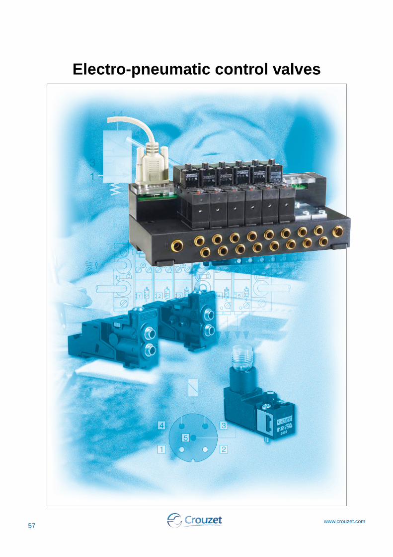
Electro-pneumatic control valves
57www.crouzet.com

58www.crouzet.com
5
81 519 68081 519 68181 519 67881 519 679
3/2 NCWith manual override by latching (1/4 turn)
81 519 080---
3/2 NCWithoutmanual override
81 519 38081 519 38181 519 37881 519 379
3/2 NCWith manual override by impulse
1-80.5120.125 • 155 107
-10 +50
●
100 % EDF35
●
IP 20IP 65MH 15085
FunctionVersion
15x15 mm footprint
according to CNOMO E 06-36-120N
Dimensions81 519 0 81 519 3
81 519 6
barmmNl/min
ms
°C
IEC 85
IEC 529IEC 529
Miniature solenoid valves for alternating current
Voltage24 V a 50-60 Hz 48 V a 50-60 Hz* 110 V a 50-60 Hz 220 V- 230 V a 50-60 Hz
Consumption2.5 VA2.5 VA2.5 VA2.5 VA
Part numbers (and voltages)
1-80.5120.125 • 155 107
-10 +50
●
100 % EDF35
●
IP 20IP 65MH 15085
1-80.5120.125 • 155 107
-10 +50
●
100 % EDF35
●
IP 20IP 65MH 15085
Operating pressureOrifice diameterFlow at 6 barskV Switching timeMechanical life (operations)Operating temperature Compressed air or inert gas - oil-freeair filtered to 50 µDuty factor Insulation classWeightRotatable connector 4 positions in 90° stepsDegree of with sub-base (page 62)protection with connector 81 516 082 (page 65) UL and cUL approval
Characteristics
9,4±0,1
1516
26
42 m
ax.
003 585 P2
Référence :Désignation :
DESSINE PAR JML
81 519 01
SODIPE
Manual override
■ Conform to the Low Voltage Directive■ For mounting on sub-base or footprint in accordance
with CNOMO recommendation E-06-36-120N
003 231 P2
Référence :Désignation :
DESSINE PAR DPH
81 519 034/035/334/335
SODIPE
6 min. 9 min.
9,7 2 1
17 m
in.
1,4
3,83,8
3
7,5 min.
7,5 min.
2 x M3 - 6 H depth 6
2 or 3 Ø 1.6 min 2 max
1 - Supply2 - Output3 - Exhaust
Adjacent side of footprint when valves mounted in bank
Solenoid valve projecting on this side

59www.crouzet.com
5
81 519 0323/2 NCWithoutmanual override
81 519 6323/2 NCWith maintained manual override
81 519 3323/2 NCWith manual override by impulse
1-80.8250.35 • 155 107
-10 +50
●
100 % EDF35
●
–IP 65MH 15085
FunctionVersion
15x15 mm footprint
according to CNOMO E 06-36-120N
barmmNl/min
ms
°C
IEC 85
IEC 529IEC 529
Miniature solenoid valves for direct current
Voltage24 V c
Consumption1 W
Part numbers (and voltages)
1-80.8250.35 • 155 107
-10 +50
●
100 % EDF35
●
–IP 65MH 15085
1-80.8250.35 • 155 107
-10 +50
●
100 % EDF35
●
–IP 65MH 15085
Operating pressureOrifice diameterFlow at 6 barskV Switching timeMechanical life (operations)Operating temperature Compressed air or inert gas - oil-freeair filtered to 50 µDuty factor Insulation classWeightRotatable connector 4 positions in 90° stepsDegree of with M12 5-pin connector protection with connector 81 516 082 UL and cUL approval
Characteristics
003 231 P2
Référence :Désignation :
DESSINE PAR DPH
81 519 034/035/334/335
SODIPE
6 min. 9 min.
9,7 2 1
17 m
in.
1,4
3,83,8
3
7,5 min.
7,5 min.
2 x M3 - 6 H depth 6
2 or 3 Ø 1.6 min 2 max
1 - Supply2 - Output3 - Exhaust
■ Conform to the Low Voltage Directive■ For mounting on sub-base or footprint in accordance
with CNOMO recommendation E-06-36-120N
Adjacent side of footprint when valves mounted in bank
Solenoid valve projecting on this side
81 519 3403/2 NFWith maintained manual override
1-80,8250,35 • 155 107
-10+50
●
100 % EDF35
●
–IP 65MH 15085
Encombrement81 519 0
9,4±0,1
1516
26
42 m
ax.
003 585 P2
Référence :Désignation :
DESSINE PAR JML
81 519 01
SODIPE
81 519 381 519 6
9,4±0,1
1521
26
42 m
ax.
003 586 P2
Référence :Désignation :
DESSINE PAR JML
81 519 3 -
SODIPE
81 519 6
Manual override
81 519 3
21
42 m
ax.
003 586 P2
Référence :Désignation :
DESSINE PAR JML
81 519 3 -
SODIPE
81 519 6
Manual override
Also available in ATEX version for use in potentially explosive atmospheres in accordance with 94/9/EC Directive
ATEX version products are available in the following catologues: Pneumatic products for explosive atmospheres or on our website www.crouzet.com

60www.crouzet.com
5
Electrical
A1 - Pilot signalA2 - Common - Earth
--
79 453 569
-81 514 161
-
81 514 101--
Pneumatic
Pneumatic indicator on outputCommon supplyCommon exhaustTorque capacityPush-in connection for semi-rigid tubingØ 4 mm (NFE 49100)Mounting
UL and cUL approvalWeightConnection
●
●
●
3
●
DIN rail 35 mmEN 50022MH 1508565
mm2
mm
g
Sub-bases for miniature solenoid valves
Part numbersPair of end basesIntermediate sub-baseAdaptor sub-base for CNOMO 06-05-80 / NFE 49066 footprint
●
●
●
3
●
DIN rail 35 mmEN 50022MH 1508530
2 screwsM4 x 10
-50
Characteristics
9 0
6616
37,8 51
A2 A1
Dimensions with miniature solenoid valve (page 58)
81 514 101 - 81 514 161 79 453 569
004 193 P2
Référence :Désignation :
DESSINE PAR DPH
79 453 569
SODIPE
14
25
21 3215
34,7
52 max.
7 m
ax.
52 m
ax.
8
Connector ref 81 516 082(rotatable in 90° steps)see page 5/11
Miniature solenoid valve 81 519 ...see page 5/4
CNOMO footprintE 06-36-120N for mountingminiature solenoid valve 81 519
Mounting on CNOMO 06-05-80/ NFE 49066 footprint
Fixing on CNOMO 06-05-80/NFE 49-066 footprint by2 cap screws M4x10(NFE 25-127)
t
1 - Supply2 - Output3 - Exhaust
61www.crouzet.com
5
003229P51
003241 P51
003234P5
Forminiature solenoid valves
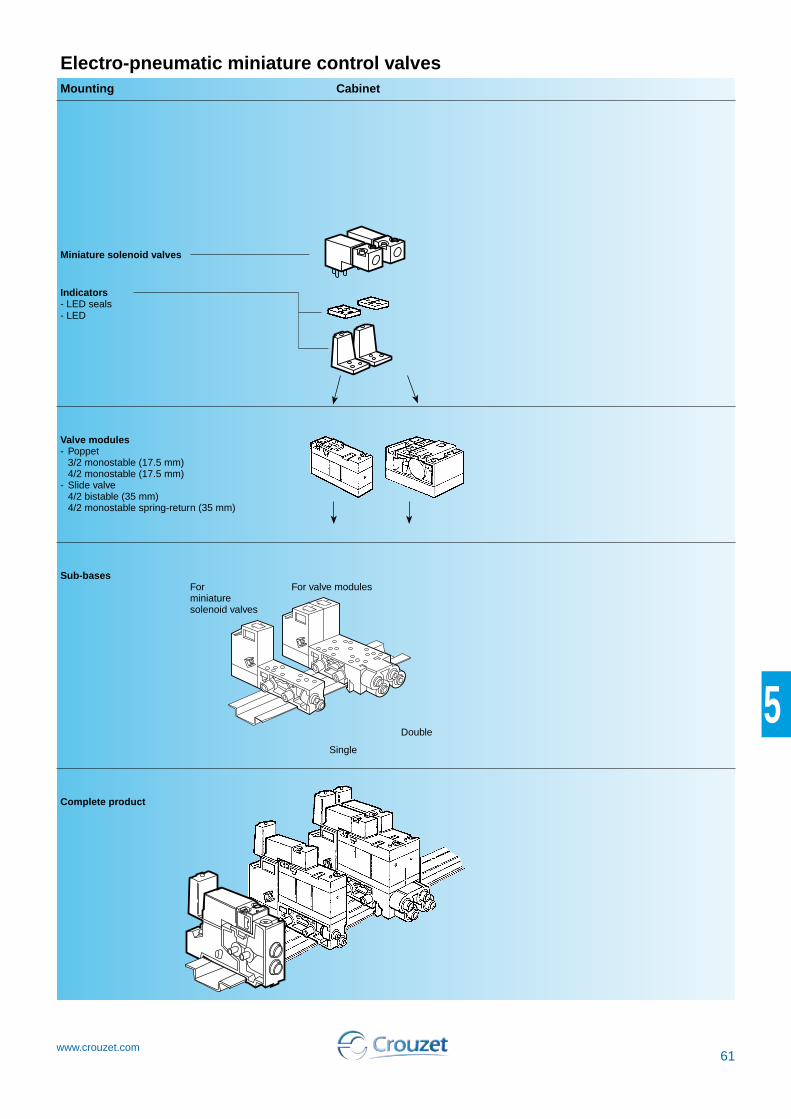
Electro-pneumatic miniature control valves
For valve modulesSub-bases
Valve modules- Poppet
3/2 monostable (17.5 mm) 4/2 monostable (17.5 mm)
- Slide valve 4/2 bistable (35 mm) 4/2 monostable spring-return (35 mm)
Single
Double
Complete product
CabinetMounting
Miniature solenoid valves
Indicators- LED seals- LED
003233P5
62www.crouzet.com
5
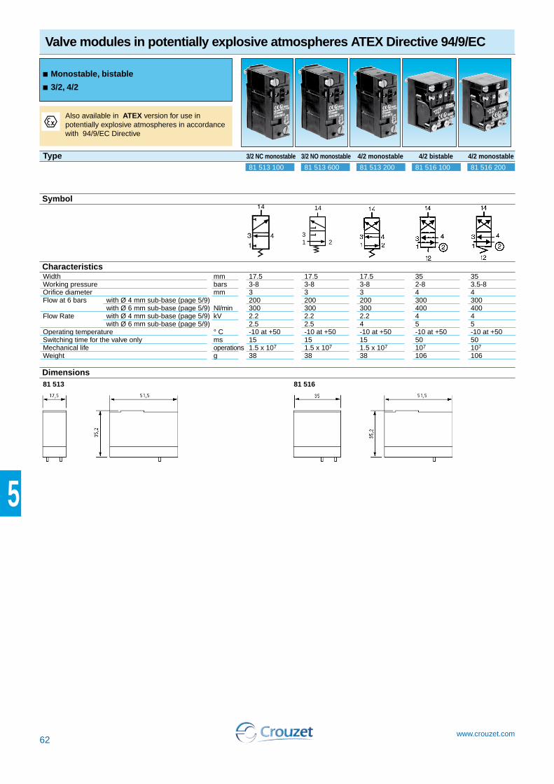
Valve modules in potentially explosive atmospheres ATEX Directive 94/9/EC
81 513 100 81 513 600 81 516 100 81 516 20081 513 200
Width mmWorking pressure barsOrifice diameter mmFlow at 6 bars with Ø 4 mm sub-base (page 5/9) with Ø 6 mm sub-base (page 5/9) Nl/minFlow Rate with Ø 4 mm sub-base (page 5/9) kV with Ø 6 mm sub-base (page 5/9) Operating temperature ° CSwitching time for the valve only msMechanical life operationsWeight g
17.53-832003002.22.5-10 at +50151.5 x 107
38
1 23
14
17.53-832003002.22.5-10 at +50151.5 x 107
38
17.53-832003002.24-10 at +50151.5 x 107
38
353.5-8430040045-10 at +5050107
106
352-8430040045-10 at +5050107
106
Type 3/2 NC monostable 3/2 NO monostable 4/2 monostable 4/2 bistable 4/2 monostable
Symbol
Characteristics
Dimensions81 513 81 516
Also available in ATEX version for use in potentially explosive atmospheres in accordance with 94/9/EC Directive
■Monostable, bistable
■3/2, 4/2

63www.crouzet.com
5
Cabinet35 mm81 517 10181 517 201
-
-
Cabinet17.5 mm81 513 06081 513 065
-
-
Cabinet---
81 513 011
-
Cabinet----
81 513 001
Torque capacityUL and cUL approval
Mounting
WeightConnections Pneumatic
Electrical
3MM15085DIN rail 35 mmEN 5002255
2 - Pneumatic output 4/2 (NO)
4 - Pneumatic output 3/2 or 4/2 (NC)
Output at rest (NO)2 Output at rest * Output at rest *4 Output operating (NC)
2 Supply ports
2 Exhaust ports
Integral push-in connections Ø 6 mm
81 513 011 - 81 513 001
mm2
g
Sub-bases and end bases for miniature control valves
Part numbers
3MM15085DIN rail 35 mmEN 50022110
--
DIN rail 35 mmEN 5002286
--
DIN rail 35 mmEN 5002244
MountingVersionPush-in connection for semi-rigid tubing (NFE 49100)
Sub-bases
End bases (pair)Intermediate supply module
Ø 4 mmØ 6 mmØ 6 mm
Ø 6 mm
Characteristics
Dimensions with miniature control valves (page 62) + miniature solenoid valves (page 58) + indicators (page 65)
2
4
02
03
Note :Each sub-base can accept- sub-base 81 513 060-065 : 1 relay 3/2 or 4/2, width 17.5 mm- sub-base 81 517 101-201 : 1 bistable relay 4/2 (width 35 mm) or 2 relays 3/2 or 4/2 (width 17.5 mm)
A1 - Pilot signalA2 - Common
Earth
A1 - Operating control signal (14)
A2 - CommonA1 - Rest control
signal (12)A2 - Common
Earth
Degree of protection :IP20 when assembled.
t
t
002 872 P2
Référence :Désignation :
DESSINE PAR ST
81513 / 81516
SODIPE
Pneumatique
1
2
3
4
1 3 1 3
5
6
1 3
80
12,5
Ø 6Ø 4
17,5 17,5 35 17,5 17,5 77 max.
Intermediate baseModule
End bases
LED indicator
35 x (n module + 1)

64www.crouzet.com
5
3-83200
-2.2
--10 + 5020
1.5 x 10⁷
-
DIN rail 35 mmEN 50022130MH15085
3-83200
-2.2
--10 + 5020
1.5 x 10⁷
-
DIN rail 35 mmEN 50022130MH15085
Operating pressure barOrifice diameter mm Flow at sub-base 81 513 060 NL/min 6 bars sub-base 81 517 101 NL/min with sub-base 81 513 060 KV with sub-base 81 517 101 Operating temperature °CSwitching time of the assembly msMechanical life (operations)at 4 bars Valve position will be maintained in the event of pressure loss and/or electrical current lossMounting
WeightUL and cUL approval
3/2 NC
Ø 4 ext.
Solenoid valve with manual override by impulse81 513 103
4/2 monostable
Ø 4 ext.
Solenoid valve with manual override by impulse81 513 203
Mini-distributeurs montés
FunctionSub-base with push-in connection for semi-rigid tubing (NFE 49100)Version
Voltage 24 VDC (+10% -15%)
Part numbers
Symbol
Autres versions
nous consulter
Characteristics
Principle of operation Dimensions
3/2 monostable module (NC)
4/2 monostable module 4/2 bistable module
Anti-return valve to prevent back pressures
Common exhaust
Common air supply
Pneumatic output
Electrical signal- Common A2- Pilot signal A1- Earth
LED indicator
Plug-in solenoid valve
Manual override
Poppet valve
Marking tag
Pneumatic indicator
g
End bases not supplied (page 63)Intermediate bases not supplied (page 63)Indicators not supplied (page 65)
002 872 P2
Référence :Désignation :
DESSINE PAR ST
81513 / 81516
SODIPE
Pneumatique
1
2
3
4
1 3 1 3
5
6
1 3
80
12,5
Ø 6Ø 4
17,5 17,5 35 17,5 17,5 77 max.
Intermediate moduleModule
End bases - one pair
LED indicator
35 x (n module + 1)

65www.crouzet.com
5
002 872 P2
Référence :Désignation :
DESSINE PAR ST
81513 / 81516
SODIPE
Pneumatique
1
2
3
4
1 3 1 3
5
6
1 3
80
12,5
Ø 6Ø 4
17,5 17,5 35 17,5 17,5 77 max.
---
●
●
--
6
0.24- 10 to + 50-
●
-●
-2
Consumption WTemperature °CConnection mm
Mounted between the pilot solenoid valve and the body of the moduleSupplied in multiples of 5Supplied in multiples of 10Packet of 10 piecesWeight
000 938 P3
Référence :Désignation :
DESSINE PAR DPH
81 513 052/055/058/059
SODIPE
81 513 05281 513 055
81 513 05881 513 059
Accessories
Part numbers
Symbol
000 897 P2
Référence :Désignation :
DESSINE PAR ST
81537001 / 81537201
SODIPE
Pneumatique
50
Ø 1
5
002 870 P2
Référence :Désignation :
DESSINE PAR DPHSODIPE
29
28 15
Connection
Dimensions
81 537 001 - 81 537 201
Mounted by plugging into push-in connector for semi-rigid tubing (NFE 49100)
81 513 052 - 81 513 055
81 513 058 - 81 513 059
Characteristics
001 351 P2
Référence :Désignation :
DESSINE PAR ST
815 160 82
SODIPE
Pneumatique
M3
Ø 14Pg 7
15,5+ 0,1
26 - 0
15,5
+ 0
,1-
0
35
15
81 516 082
g
12
Pilotsignal
Earth (4)t
---
-
-- -
30
---
-
●
-10
--
Instantané Ø 4 ext.
-
●
-5
---
-
-●
●
3
Symbol
81 513 05281 513 05581 513 058
81 513 059
-(by 5)
----
-
-
-
---
-
81 513 064(by 10)
----
-
-
-
---
-
-
---
81 516 081
81 516 091
●
-
---
-
-
--
81 516 082-
-
-
-
---
-
-
81 537 00181 537 201 --
-
-
-
---
-
-
----
-
-
81 516 085
Visual 24 V - 50-60 Hz cindicators 48 V - 50-60 Hz cwith anti- 110 V - 50-60 Hz csurge 230 V - 50-60 Hz (-10% +6 %)
LED seal 12 to 24 V - DC - ACPackaging Exhaust Plug-in Ø 6silencer Plug-in Ø 8Connector for solenoid valve Without manual overridePneumatic With manual overridepilots by impulsePush-in connection for semi-rigid tubingØ 4 mm (NFE 49100)Blanking plate

66www.crouzet.com
5
2 → 82.7170
●
IP 65
1.5 x 10⁷
12.5-5 +5070MH15085
Operating pressure barOrifice diameter mmFlow at 6 bars Nl/min Rotatable coil 4 positions in 90° stepsDegree of protection (with connector 81 516 082 not supplied) (see page 65) IEC 529Mechanical life operations c WConsumption ~ VAOperating temperature °CWeight gUL and cUL approvalPrinciple of operation
FunctionMountingSolenoid valves 24 V (+10% -15%)with 24 V - 50/60 Hz (+10% -15%)manual 48V - 50/60 Hz (+10% -15%)override 110 V - 50/60 Hz (+10% -15%) by impulse 220 - 230 V - 50/60 Hz (+10% -15%)
3/2 NCOn sub-base (54)81 519 73281 519 77481 519 77581 519 77681 519 777
Solenoid valves
Part numbers and voltages
Symbol
Characteristics
Connections
1 - Supply Pneumatic 2 - Output
1 - 2 - Pilot signal Electrical t Earth
1-2
Dimensions81 519
On separate sub-base
Electrical connection by connector 81 516 062 (see page 65)
{
{
■Reduced "dimensions"
■Mounted on sub-base

67www.crouzet.com
5
1
➜ Electro-pneumatic interface block
Complete block, ready to install, consisting of: ■ Preconfigured 8-position sub-base ■ 6 4/2 monostable valve modules with 24 Vc pilot
holes ■ 2 blanking plates (for extension if necessary) ■ 1 connection cable
16 outputs 16 outputs
Part numbers 81513241 81513238
Electrical characteristicsSupply voltage 24 Vc ± -10% 24 Vc ± -10%Courant max. absorbé sur le 24 V de SUBD (mA) 500 500Courant absorbé par chaque électrovanne 60 60Response time (ms) 15 15LED display Yes (integrated in the sub-base) Yes (integrated in the sub-base)Protection against voltage surges Yes YesElectrical connectionsType of cable Sub D9 AWG 24 wires Sub D9 AWG 24 wiresCable length 2 m 2 mPneumatic characteristicsFunction 6 4/2 monostable valve
modules (81513200) + 2 free positions
Whitout
Operating pressure bars 3 ➞ 8 b 3 ➞ 8 bFlow at 6 bars NL/mim 300 300Mechanical life (operations) 1.5 x 10⁷ 1.5 x 10⁷
Working medium Compressed air or inert gas, 50 µm filtered non-lubricated air
Compressed aire or inet gaés, 50 µm filtered non-lubricated air
Pneumatic connectionsPower supply connection Push-in connection Ø 8 mm Push-in connection Ø 8 mmOutput connections Push-in connection Ø 6 mm Push-in connection Ø 6 mmConnection of common exhaust Push-in connection Ø 8 mm Push-in connection Ø 8 mmGeneral characteristicsOperating temperature range IEC 68214 (oC) -5 ➞ +50 -5 ➞ +50Storage temperature IEC 68-2-14 (°C) -15 ➞ +50 -15 ➞ +50Protection (IEC/EN 60529) IP 20 IP20Mounting On DIN rail or via two M5
screws (according to mounting plan)
On DIN rail or via two M5 screws (according to mounting plan)
Weight (g) 1350CommentsOther configurations on request
81513241 Connector wiring
Commun 0 V
Clips femelle Cl
Miniature control valves, 17.5 mm
Part numbers
Dimensions (mm) Connections
2 2 2 2 2
4
A E
213
EV
93
88,5
4 4 4
2 2 2
EV1 ...... EV6
1
2
1 2 3
6 7 8 9
4 5
1
1
2

68www.crouzet.com
5
Specific islands "for integrators" (supplied in packs of 20)
Versions with interfaces 300 NL / mm
Versions with interfaces 30 NL / mm
Develop customised versions to specifications
Configuration1 - Specify the number and type of interfaces (3 / 2 mono -
4 / 2 mono - 4 / 2 bistable) see page 62.2 - Specify the voltage, the type and method of the control
valve connections, see page: 58-59 (Example: 24 V DC with manual switch maintained, exit leads).
3 - Please send us your application specifying your requirements and quantities per year, and we will respond as soon as possible.
Configuration 1 - Specify the voltage, the type and method of the control
valve connections, see page: 58-59 (Example: 24 V DC with manual switch maintained, exit leads).
2 - Please send us your application specifying your requirements and quantities per year, and we will respond as soon as possible.
Crouzet analyses your needs and offers a customised solution.


