FULL PAPER Mesoporous Materials Xuecheng Chen,* Krzysztof Kierzek, Karolina Wenelska, Krzystof Cendrowski, Jiang Gong, Xin Wen, Tao Tang,* PaulK. Chu,* Ewa Mijowska &&&&—&&&& Electrochemical Characteristics of Discrete, Uniform, and Monodispersed Hollow Mesoporous Carbon Spheres in Double-Layered Supercapacitors I)m so hollow: Hollow mesoporous carbon spheres with controllable diam- eters are fabricated by chemical vapor deposition and used as electrode mate- rials in supercapacitors. The perfor- mance of hollow carbon spheres with a wall thickness of 25 nm synthesized at 700 8C is the best, as manifested by their highest specific capacitance in a wide range of charging–discharging rates. Chem. Asian J. 2013, 00,0–0 # 2013 Wiley-VCH Verlag GmbH & Co. KGaA, Weinheim 1 && These are not the final page numbers! ÞÞ FULL PAPER
Transcript
FULL PAPER
Mesoporous Materials
Xuecheng Chen,* Krzysztof Kierzek,Karolina Wenelska,Krzystof Cendrowski, Jiang Gong,Xin Wen, Tao Tang,* Paul K. Chu,*Ewa Mijowska &&&&—&&&&
I�m so hollow: Hollow mesoporouscarbon spheres with controllable diam-eters are fabricated by chemical vapordeposition and used as electrode mate-rials in supercapacitors. The perfor-mance of hollow carbon spheres witha wall thickness of 25 nm synthesizedat 700 8C is the best, as manifested bytheir highest specific capacitance ina wide range of charging–dischargingrates.
Chem. Asian J. 2013, 00, 0 – 0 � 2013 Wiley-VCH Verlag GmbH & Co. KGaA, Weinheim1 &&
Electrochemical Characteristics of Discrete, Uniform, and MonodispersedHollow Mesoporous Carbon Spheres in Double-Layered Supercapacitors
Xuecheng Chen,*[a, c] Krzysztof Kierzek,[b] Karolina Wenelska,[a] Krzystof Cendrowski,[a]
Jiang Gong,[c] Xin Wen,[c] Tao Tang,*[c] Paul K. Chu,*[d] and Ewa Mijowska[a]
Introduction
Supercapacitors are very attractive power sources. They areessentially maintenance free, require a very simple chargingcircuit, experience no memory effect, and they possessa longer cycle life and are generally much safer than batter-ies.[1] More importantly, supercapacitors can be charged anddischarged at high rates, and one of the most promising ap-plications of supercapacitors is in electric vehicles. Superca-pacitors have two energy-storage mechanisms: electricdouble-layer (EDL) capacitance and pseudocapacitance.
Currently, EDL capacitors contain activated carbon (AC)with a high surface area as the electrode materials, and thecapacitance comes from the charge accumulated at the elec-trode/electrolyte interface. In contrast, pseudocapacity isachieved by introducing a conducting polymer or metaloxide or surface functionalities into the electrode materialsto trigger reversible Faradic redox reactions. Carbon materi-als such as AC usually exhibit good stability but limitedEDL capacitance.[2,3] Hence, there is a need to identify moresuitable carbon materials with high specific capacitance toreplace AC.
Hollow spheres have attracted much attention as a resultof their hollow inner space, which is useful in applicationssuch as drug delivery,[4] catalysis,[5] electrochemistry,[6] photo-electronics,[7] adsorption,[8] environment protection,[9] energystorage,[10] and biomedical engineering.[11] Among the differ-ent kinds of hollow spheres, hollow carbon spheres (HCS)have been widely studied because of their chemical inert-ness, lightness, good mechanical properties, and economicalsources.[12] There are several ways to synthesize HCS. Nano-casting methods are most widely used.[13] In this technique,templates are frequently employed because the resultingcarbon spheres are monodispersed and the diameter can becontrolled. Other methods such as chemical vapor deposi-tion (CVD)[14–18] and hydrothermal methods[19–23] typically in-volve three steps including impregnation, carbonization, andtemplate removal. Nevertheless, the template synthesisroute is tedious and often expensive. Furthermore, most ofthe HCS obtained are not discrete and instead are aggregat-ed. It is desirable to be able to produce monodispersed, dis-crete HCS by using a simple, cost-effective, and efficienttechnique. In our previous paper, we reported a two-step
Abstract: Core–shell-structured meso-porous silica spheres were prepared byusing n-octadecyltrimethoxysilane(C18TMS) as the surfactant. Hollowmesoporous carbon spheres with con-trollable diameters were fabricatedfrom core–shell-structured mesoporoussilica sphere templates by chemicalvapor deposition (CVD). By control-ling the thickness of the silica shell,hollow carbon spheres (HCSs) with dif-ferent diameters can be obtained. The
use of ethylene as the carbon precursorin the CVD process produces the mate-rials in a single step without the needto remove the surfactant. The mecha-nism of formation and the role playedby the surfactant, C18TMS, are investi-gated. The materials have large poten-
tial in double-layer supercapacitors,and their electrochemical propertieswere determined. HCSs with thickermesoporous shells possess a larger sur-face area, which in turn increases theirelectrochemical capacitance. The sam-ples prepared at a lower temperaturealso exhibit increased capacitance asa result of the Brunauer–Emmett–Teller (BET) area and larger pore size.
[a] Dr. X. Chen, K. Wenelska, K. Cendrowski, Prof. E. MijowskaInstitute of Chemical and Environment EngineeringWest Pomeranian University of Technologyul. Pulaskiego 10, 70-322 Szczecin (Poland)Fax: (+48) 91449486E-mail : [email protected]
[b] Dr. K. KierzekDepartment of Polymer and Carbonaceous MaterialsWroclaw University of Technologyul. Gdanska 7/9, 50344 Wroclaw (Poland)
[c] Dr. X. Chen, J. Gong, Dr. X. Wen, Prof. T. TangState Key Laboratory of Polymer Physics and ChemistryChangchun Institute of Applied ChemistryChinese Academy of ScienceRenmin road 5625, Changchun (China)E-mail : [email protected]
[d] Prof. P. K. ChuDepartment of Physics and Materials ScienceCity University of Hong KongTat Chee Avenue, Kowloon, Hong Kong (China)E-mail : [email protected]
Supporting information for this article is available on the WWWunder http://dx.doi.org/10.1002/asia.201300093.
Chem. Asian J. 2013, 00, 0 – 0 � 2013 Wiley-VCH Verlag GmbH & Co. KGaA, Weinheim2&&
�� These are not the final page numbers!
www.chemasianj.org Xuecheng Chen et al.
method by which hollow mesoporous carbon spheres weresynthesized from core–shell-structured silica sphere tem-plates by using CVD without removing the hexadecyltrime-thylammonium bromide (CTAB) surfactant.[24,25] By control-ling the mesoporous shell thickness, HCS with differentshell thicknesses were synthesized. The HCS were monodis-persed and discrete, and it was postulated that CTAB servedas the carbon seed in the subsequent CVD process. To fur-ther clarify whether the head [�ACHTUNGTRENNUNG(NH4)
+Br�] or tail [�C16H33]of CTAB was the carbon seed, n-octadecyltrimethoxysilane(C18TMS) was chosen as the surfactant to synthesize themesoporous wall of the silica spheres. Experimentally, onlythose having the tail structure, �C18H37, were successful inthe carbonization process, which suggests that the tail wasthe actual carbon seed in the CVD process.
The specific capacitance of a supercapacitor is related tothe specific surface area of the electrode materials and, atthe same time, the specific surface area depends on the wallthickness of the HCS. In this study, three types of HCS withdifferent wall thicknesses were synthesized and evaluated aselectrode materials in supercapacitors. The objective was toelucidate the relationship between the wall thickness andspecific capacitance of different types of HCS. The synthesistemperature also affects the specific capacitance, and theimpact of this important parameter was also investigated.Our study revealed that a large Brunauer–Emmett–Teller(BET) area does not guarantee high specific capacitanceand that only a suitable wall thickness of the HCS and thesynthesis temperature yield improved specific capacitance.
Results and Discussion
Synthesis and Characterization
The synthetic process is illustrated schematically inScheme 1. Silica spheres are first synthesized, and with theaid of the C18TMS surfactant template, the mesostructuredC18TMS/silica composite is deposited on the silica spheresto produce well-dispersed core–shell mesoporous silicaspheres. The materials with trapped C18TMS are placed in
a horizontal quartz reactor, and after CVD and etching ofthe silica template by HF, hollow mesoporous carbonspheres are obtained. By varying the thickness of the meso-porous silica shell deposited on the bare silica spheres, HCSwith different diameters are produced. The presence ofC18TMS is very important, as it carbonizes the nanocarbonseeds that are used in the subsequent CVD process.
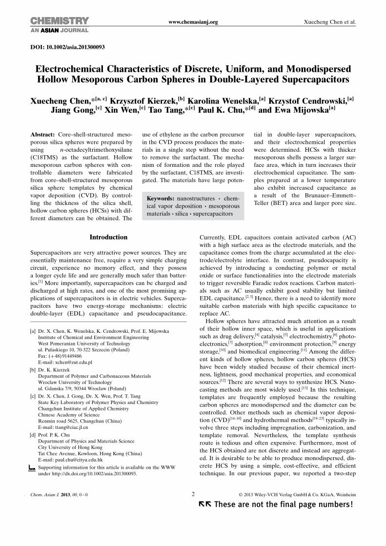
To examine the morphology of the carbon materials,TEM was conducted (Figure 1). The TEM images show
carbon nanoparticles with mesoporous hollow structures.The HCS are monodispersed and the silica templates arecompletely removed. The shells of these spheres exhibita mesoporous structure containing confined pores. TEM in-dicates that CVD is a practical technique to produce dis-crete, dispersed, and uniform HCS. The diameter and shellthickness can be tailored by adjusting the synthesis condi-tions. As shown in the TEM images in Figure 1 a, d,g, HCSwith diameters of 235, 260, and 290 nm can be synthesized.High-resolution TEM images of the shell structures are de-picted in Figure 1 c, f, i.
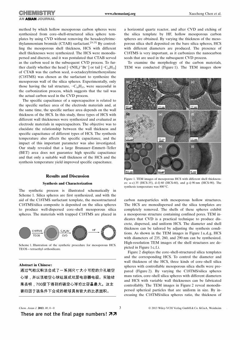
Figure 2 displays the core–shell-structured silica templatesand the corresponding HCS. To control the diameter andwall thickness of the HCS, three kinds of core–shell silicaspheres with controllable mesoporous silica shells were pre-pared (Figure 2). By varying the C18TMS/silica spheresmass ratios, core–shell silica spheres with different diametersand HCS with variable wall thicknesses can be fabricatedcontrollably. The TEM images in Figure 2 reveal monodis-persed spherical particles that are uniform in size. By in-creasing the C18TMS/silica spheres ratio, the thickness of
Abstract in Chinese:
Scheme 1. Illustration of the synthetic procedure for mesoporous HCS.TEOS = tetraethyl orthosilicate.
Figure 1. TEM images of mesoporous HCS with different shell thickness-es: a–c) 35 (HCS-35), d–f) 60 (HCS-60), and g–i) 90 nm (HCS-90). Thesynthesis temperature was 800 8C.
Chem. Asian J. 2013, 00, 0 – 0 � 2013 Wiley-VCH Verlag GmbH & Co. KGaA, Weinheim3 &&
These are not the final page numbers! ��
www.chemasianj.org Xuecheng Chen et al.
the porous shell increased from 25 to 90 nm. The threekinds of core–shell silica spheres are shown in Figure 2 a–c.After CVD and complete removal of the silica template,hollow mesoporous carbon spheres with different diameterswere produced, as shown in Figure 2 d–f. Comparing thesilica spheres to the corresponding HCS, the shell thickness-es of the HCS increased slightly from 25 to 35 nm and from45 to 60 nm. At 700 8C, the same SiO2@m-SiO2-C18TMS-ACHTUNGTRENNUNG(45 nm) (m-SiO2 =mesoporous silica) template was used.Upon completion of the CVD reaction and removal of thesilica components, HCS were also obtained. As shown inFigure 2 g–i, HCS with a wall thickness of 25 nm were alsosynthesized, and the hollow spheres look very soft [HCS-25-ACHTUNGTRENNUNG(700 8C)].
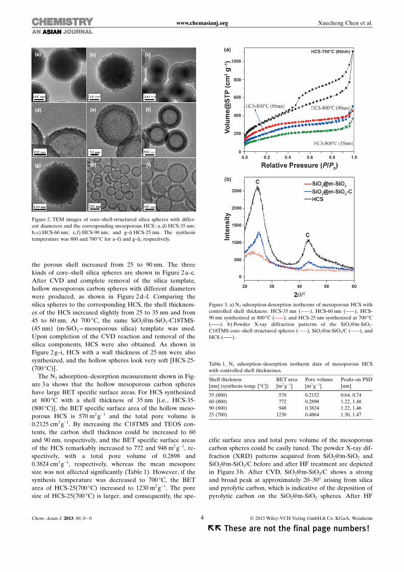
The N2 adsorption–desorption measurement shown in Fig-ure 3 a shows that the hollow mesoporous carbon sphereshave large BET specific surface areas. For HCS synthesizedat 800 8C with a shell thickness of 35 nm [i.e., HCS-35-ACHTUNGTRENNUNG(800 8C)], the BET specific surface area of the hollow meso-porous HCS is 570 m2 g�1 and the total pore volume is0.2125 cm3 g�1. By increasing the C18TMS and TEOS con-tents, the carbon shell thickness could be increased to 60and 90 nm, respectively, and the BET specific surface areasof the HCS remarkably increased to 772 and 948 m2 g�1, re-spectively, with a total pore volume of 0.2898 and0.3824 cm3 g�1, respectively, whereas the mean mesoporesize was not affected significantly (Table 1). However, if thesynthesis temperature was decreased to 700 8C, the BETarea of HCS-25 ACHTUNGTRENNUNG(700 8C) increased to 1230 m2 g�1. The poresize of HCS-25 ACHTUNGTRENNUNG(700 8C) is larger, and consequently, the spe-
cific surface area and total pore volume of the mesoporouscarbon spheres could be easily tuned. The powder X-ray dif-fraction (XRD) patterns acquired from SiO2@m-SiO2 andSiO2@m-SiO2/C before and after HF treatment are depictedin Figure 3 b. After CVD, SiO2@m-SiO2/C shows a strongand broad peak at approximately 20–308 arising from silicaand pyrolytic carbon, which is indicative of the deposition ofpyrolytic carbon on the SiO2@m-SiO2 spheres. After HF
Figure 2. TEM images of core–shell-structured silica spheres with differ-ent diameters and the corresponding mesoporous HCS: a,d) HCS-35 nm;b,e) HCS-60 nm; c, f) HCS-90 nm; and g–i) HCS-25 nm. The synthesistemperature was 800 and 700 8C for a–f) and g–i), respectively.
Figure 3. a) N2 adsorption-desorption isotherms of mesoporous HCS withcontrolled shell thickness: HCS-35 nm (c), HCS-60 nm (c), HCS-90 nm synthesized at 800 8C (c), and HCS-25 nm synthesized at 700 8C(c). b) Powder X-ray diffraction patterns of the SiO2@m-SiO2-C18TMS core–shell structured spheres (c), SiO2@m-SiO2/C (c), andHCS (c).
Table 1. N2 adsorption–desorption isotherm data of mesoporous HCSwith controlled shell thicknesses.
Shell thickness[nm] (synthesis temp. [8C])
BET areaACHTUNGTRENNUNG[m2 g�1]Pore volumeACHTUNGTRENNUNG[m3 g�1]
Chem. Asian J. 2013, 00, 0 – 0 � 2013 Wiley-VCH Verlag GmbH & Co. KGaA, Weinheim4&&
�� These are not the final page numbers!
www.chemasianj.org Xuecheng Chen et al.
treatment for 24 h, the broad peak (20–308) disappears andonly two strong peaks emerge at 25.1 and 438, and thisshows that the silica was completely removed from SiO2@m-SiO2/C and that only the pyrolytic carbon structure re-mained in the sample. These two peaks appear at the samereciprocal spacing as (002) and (101) carbon reflections, re-spectively.
The bonding, order, and crystallinity of the materials werestudied by Raman spectroscopy (Figure 4 a). The presence
of disordered graphitic materials is suggested by the twoRaman modes. The peak at 1593 cm�1 (G band) correspondsto the E2g mode of hexagonal graphite and is related to thevibration of the sp2-hybridized carbon atoms in a graphitelayer. This implies that the HCS are composed of graphiticcarbon, and this is consistent with the TEM and XRD re-sults. The D band at approximately 1359 cm�1 is associatedwith the vibration of carbon atoms with dangling bonds inthe plane with termination by disordered graphite. TheTGA measurements in Figure 4 b impart information aboutthe carbon content as well as the quality of the carbonspheres, because the oxidation temperature affects the walldefects. Graphite starts to oxidize at 752 8C, but the HCSwere oxidized above 500 8C. The HCS began to decomposeat 593 8C in air. As the temperature was further increased,the weight loss increased rapidly until all of the carbon
spheres were exhausted at approximately 700 8C. The ashcontent of the HCS after combustion at 900 8C was 0 % (w/w), which implies that the HCS have high purity.
The effects of C18TMS on the synthesis temperature ofthe HCS were also studied. C18TMS lowers the reactiontemperature. At 800 8C, CVD was successful for both kindsof silica spheres, with and without the surfactant. However,if the temperature was lowered to 700 8C, the CVD reactionwas successful only in the presence of the C18TMS surfac-tant. Lowering the temperature further to 600 8C led to un-successful CVD, and 650 8C was the lowest temperature forthe production of HCS.
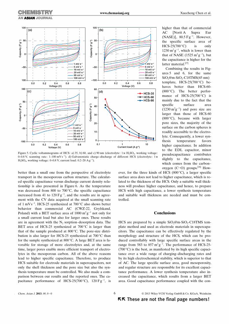
Figure 5 a–c shows representative cyclic voltammetry(CV) traces recorded at various scanning rates from capaci-tors incorporating the HCS with different shell thicknesses.The current response (I) at various potentials was convertedinto specific capacitance (C) by using the equation C=2 I/(vm), in which v is the scanning rate and m is the mass ofthe active materials. It is well known that the capacitance ofan ideal supercapacitor is independent of the charging–dis-charging rate and that the electrical charge stored in the ca-pacitor is proportional to the voltage applied. Therefore, fora constant sweep rate (in mV s�1), the current response re-mains constant in the CV measurements. An importantcharacteristic of electrical energy storage in a capacitor isthat the energy is retrievable upon discharging over thesame potential range as that required to store the energyupon charging; otherwise, energy storage is limited.
Typical cyclic voltammograms were obtained from all ofthe HCS electrodes. The rectangular shape and humps inthe CV curves indicate that the capacitive response is de-rived from the combination of the EDL capacitor and redoxreactions. For the HCS synthesized at 800 8C, the specific ca-pacitance values are 47, 41, and 38 Fg�1 for HCS-35, HCS-60, and HCS-90, respectively, at a current density of0.2 Ag�1. Figure 5 d presents the relationship between thespecific capacitance and charging–discharging current densi-ty. For a small current load, the specific capacitance ofHCS-35 is higher than that of HCS-60 and HCS-90. Howev-er, in the high current load area, HCS-60 shows the highestspecific capacitance. Comparing the specific surface areas tothe specific capacitances of different HCS, no direct rela-tionship between large surface area and higher specific ca-pacitance is observed. However, higher specific capacitanceis achieved only by controlling the shell thickness and poresize. As a result of diffusion, the lower mobility of the sul-fate anions (effective size of �0.53 nm[26]) in the narrowpores of HCS-35 can be the main reason for the compro-mised performance of the materials.
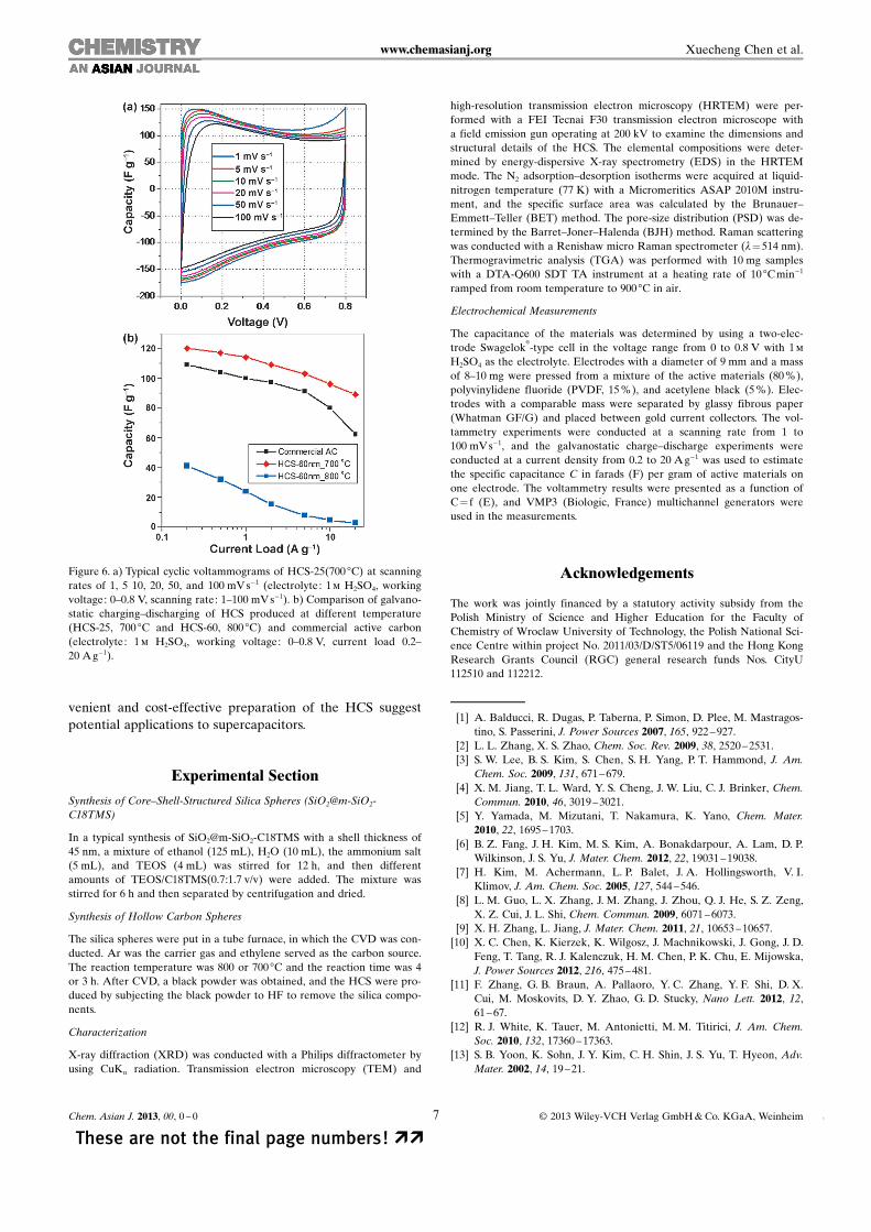
Figure 6 a presents the CV curves of HCS-25 ACHTUNGTRENNUNG(700 8C), andsurprisingly, the specific capacitance reaches 120 Fg�1 ata scanning rate of 1 mV s�1. This is much higher than thespecific capacitance of HCS-60 ACHTUNGTRENNUNG(800 8C). The results suggestthat a lower synthesis temperature increases the specific ca-pacitance of the HCS. The improved capacitance can be as-cribed to a proper pore-size distribution (PSD, Table 1) andthe regular structure of HCS-25ACHTUNGTRENNUNG(700 8C). A large pore is
Figure 4. a) Raman spectra of mesoporous HCS with a shell thickness of90 nm. b) TGA profile of the mesoporous carbon hollow spheres witha shell thickness of 90 nm. The synthesis temperature was 800 8C.
Chem. Asian J. 2013, 00, 0 – 0 � 2013 Wiley-VCH Verlag GmbH & Co. KGaA, Weinheim5 &&
These are not the final page numbers! ��
www.chemasianj.org Xuecheng Chen et al.
better than a small one from the perspective of electrolytetransport in the mesoporous carbon structure. The calculat-ed specific capacitance versus discharge current density rela-tionship is also presented in Figure 6. As the temperaturewas decreased from 800 to 700 8C, the specific capacitanceincreased from 41 to 120 Fg�1, and the results are in agree-ment with the CV data acquired at the small scanning rateof 1 mV s�1. HCS-25 synthesized at 700 8C also shows betterbehavior than commercial AC (CWZ-22, Gryfskand,Poland) with a BET surface area of 1000 m2 g�1 not only fora small current load but also for larger ones. These resultsare in agreement with the N2 sorption–desorption data. TheBET area of HCS-25 synthesized at 700 8C is larger thanthat of the sample produced at 800 8C. The pore-size distri-bution is also larger for HCS-25 synthesized at 700 8C thanfor the sample synthesized at 800 8C. A large BET area is fa-vorable for storage of more electrolytes and, at the sametime, larger pores enable more efficient transport of electro-lytes in the mesoporous carbon. All of the above reasonslead to higher specific capacitance. Therefore, to produceHCS suitable for electrode materials in supercapacitors, notonly the shell thickness and the pore size but also the syn-thesis temperature must be controlled. We also made a com-parison between our results and the reported ones. The ca-pacitance performance of HCS-25 ACHTUNGTRENNUNG(700 8C), 120 F g�1, is
higher than that of commercialAC [Norit A Supra Eur(NASE)], 80.5 F g�1. However,the specific surface area ofHCS-25 ACHTUNGTRENNUNG(700 8C) is only1230 m2 g�1, which is lower thanthat of NASE (1525 m2 g�1), butthe capacitance is higher for thelatter material.[27]
Combining the results in Fig-ures 5 and 6, for the sameSiO2@m-SiO2-C18TMS ACHTUNGTRENNUNG(45 nm)template, HCS-25 ACHTUNGTRENNUNG(700 8C) be-haves better than HCS-60-ACHTUNGTRENNUNG(800 8C). The better perfor-mance of HCS-25 ACHTUNGTRENNUNG(700 8C) ismainly due to the fact that thespecific surface area(1230 m2g�1) and pore size arelarger than those of HCS-60(800 8C), because with largerpore sizes, the majority of thesurface on the carbon spheres isreadily accessible to the electro-lyte. Consequently, a lower syn-thesis temperature favorshigher capacitance. In additionto the EDL capacitor, minorpseudocapacitance contributesslightly to the capacitance,which comes from the carbon–oxygen (C�O) groups.[28] How-
ever, for the three kinds of HCS (800 8C), a larger specificsurface area does not lead to higher capacitance, which is re-lated to the thickness of the HCS. Only a suitable wall thick-ness will produce higher capacitance, and hence, to prepareHCS with high capacitance, a lower synthesis temperatureand suitable wall thickness are needed and must be con-trolled.
Conclusions
HCS are prepared by a simple SiO2@m-SiO2-C18TMS tem-plate method and used as electrode materials in supercapa-citors. The capacitance can be effectively regulated by themorphology and structure of the HCS, which can be pro-duced controllably with large specific surface areas in therange from 583 to 857 m2 g�1. The performance of HCS-25-ACHTUNGTRENNUNG(700 8C) is the best, as manifested by its high specific capaci-tance over a wide range of charging–discharging rates andby its high electrochemical stability, which is superior to thatof AC. The large specific surface area, good mesoporosity,and regular structure are responsible for its excellent capaci-tance performance. A lower synthesis temperature also in-creased the capacitance, which results from a larger BETarea. Good capacitance performance coupled with the con-
Figure 5. Cyclic voltammograms of HCS: a) 35, b) 60, and c) 90 nm (electrolyte: 1 m H2SO4, working voltage:0–0.8 V, scanning rate: 1–100 mV s�1). d) Galvanostatic charge–discharge of different HCS (electrolyte: 1 m
H2SO4, working voltage: 0–0.8 V, current load: 0.2–20 A g�1).
Chem. Asian J. 2013, 00, 0 – 0 � 2013 Wiley-VCH Verlag GmbH & Co. KGaA, Weinheim6&&
�� These are not the final page numbers!
www.chemasianj.org Xuecheng Chen et al.
venient and cost-effective preparation of the HCS suggestpotential applications to supercapacitors.
Experimental Section
Synthesis of Core–Shell-Structured Silica Spheres (SiO2@m-SiO2-C18TMS)
In a typical synthesis of SiO2@m-SiO2-C18TMS with a shell thickness of45 nm, a mixture of ethanol (125 mL), H2O (10 mL), the ammonium salt(5 mL), and TEOS (4 mL) was stirred for 12 h, and then differentamounts of TEOS/C18TMS(0.7:1.7 v/v) were added. The mixture wasstirred for 6 h and then separated by centrifugation and dried.
Synthesis of Hollow Carbon Spheres
The silica spheres were put in a tube furnace, in which the CVD was con-ducted. Ar was the carrier gas and ethylene served as the carbon source.The reaction temperature was 800 or 700 8C and the reaction time was 4or 3 h. After CVD, a black powder was obtained, and the HCS were pro-duced by subjecting the black powder to HF to remove the silica compo-nents.
Characterization
X-ray diffraction (XRD) was conducted with a Philips diffractometer byusing CuKa radiation. Transmission electron microscopy (TEM) and
high-resolution transmission electron microscopy (HRTEM) were per-formed with a FEI Tecnai F30 transmission electron microscope witha field emission gun operating at 200 kV to examine the dimensions andstructural details of the HCS. The elemental compositions were deter-mined by energy-dispersive X-ray spectrometry (EDS) in the HRTEMmode. The N2 adsorption–desorption isotherms were acquired at liquid-nitrogen temperature (77 K) with a Micromeritics ASAP 2010M instru-ment, and the specific surface area was calculated by the Brunauer–Emmett–Teller (BET) method. The pore-size distribution (PSD) was de-termined by the Barret–Joner–Halenda (BJH) method. Raman scatteringwas conducted with a Renishaw micro Raman spectrometer (l=514 nm).Thermogravimetric analysis (TGA) was performed with 10 mg sampleswith a DTA-Q600 SDT TA instrument at a heating rate of 10 8C min�1
ramped from room temperature to 900 8C in air.
Electrochemical Measurements
The capacitance of the materials was determined by using a two-elec-trode Swagelok
�
-type cell in the voltage range from 0 to 0.8 V with 1 m
H2SO4 as the electrolyte. Electrodes with a diameter of 9 mm and a massof 8–10 mg were pressed from a mixture of the active materials (80 %),polyvinylidene fluoride (PVDF, 15 %), and acetylene black (5 %). Elec-trodes with a comparable mass were separated by glassy fibrous paper(Whatman GF/G) and placed between gold current collectors. The vol-tammetry experiments were conducted at a scanning rate from 1 to100 mV s�1, and the galvanostatic charge–discharge experiments wereconducted at a current density from 0.2 to 20 A g�1 was used to estimatethe specific capacitance C in farads (F) per gram of active materials onone electrode. The voltammetry results were presented as a function ofC= f (E), and VMP3 (Biologic, France) multichannel generators wereused in the measurements.
Acknowledgements
The work was jointly financed by a statutory activity subsidy from thePolish Ministry of Science and Higher Education for the Faculty ofChemistry of Wroclaw University of Technology, the Polish National Sci-ence Centre within project No. 2011/03/D/ST5/06119 and the Hong KongResearch Grants Council (RGC) general research funds Nos. CityU112510 and 112212.
[1] A. Balducci, R. Dugas, P. Taberna, P. Simon, D. Plee, M. Mastragos-tino, S. Passerini, J. Power Sources 2007, 165, 922 –927.
[2] L. L. Zhang, X. S. Zhao, Chem. Soc. Rev. 2009, 38, 2520 –2531.[3] S. W. Lee, B. S. Kim, S. Chen, S. H. Yang, P. T. Hammond, J. Am.
Chem. Soc. 2009, 131, 671 –679.[4] X. M. Jiang, T. L. Ward, Y. S. Cheng, J. W. Liu, C. J. Brinker, Chem.
Commun. 2010, 46, 3019 –3021.[5] Y. Yamada, M. Mizutani, T. Nakamura, K. Yano, Chem. Mater.
2010, 22, 1695 –1703.[6] B. Z. Fang, J. H. Kim, M. S. Kim, A. Bonakdarpour, A. Lam, D. P.
Wilkinson, J. S. Yu, J. Mater. Chem. 2012, 22, 19031 –19038.[7] H. Kim, M. Achermann, L. P. Balet, J. A. Hollingsworth, V. I.
Klimov, J. Am. Chem. Soc. 2005, 127, 544 –546.[8] L. M. Guo, L. X. Zhang, J. M. Zhang, J. Zhou, Q. J. He, S. Z. Zeng,
X. Z. Cui, J. L. Shi, Chem. Commun. 2009, 6071 –6073.[9] X. H. Zhang, L. Jiang, J. Mater. Chem. 2011, 21, 10653 –10657.
[10] X. C. Chen, K. Kierzek, K. Wilgosz, J. Machnikowski, J. Gong, J. D.Feng, T. Tang, R. J. Kalenczuk, H. M. Chen, P. K. Chu, E. Mijowska,J. Power Sources 2012, 216, 475 – 481.
[11] F. Zhang, G. B. Braun, A. Pallaoro, Y. C. Zhang, Y. F. Shi, D. X.Cui, M. Moskovits, D. Y. Zhao, G. D. Stucky, Nano Lett. 2012, 12,61– 67.
[12] R. J. White, K. Tauer, M. Antonietti, M. M. Titirici, J. Am. Chem.Soc. 2010, 132, 17360 –17363.
[13] S. B. Yoon, K. Sohn, J. Y. Kim, C. H. Shin, J. S. Yu, T. Hyeon, Adv.Mater. 2002, 14, 19–21.
Figure 6. a) Typical cyclic voltammograms of HCS-25 ACHTUNGTRENNUNG(700 8C) at scanningrates of 1, 5 10, 20, 50, and 100 mV s�1 (electrolyte: 1 m H2SO4, workingvoltage: 0–0.8 V, scanning rate: 1–100 mV s�1). b) Comparison of galvano-static charging–discharging of HCS produced at different temperature(HCS-25, 700 8C and HCS-60, 800 8C) and commercial active carbon(electrolyte: 1 m H2SO4, working voltage: 0–0.8 V, current load 0.2–20 Ag�1).
Chem. Asian J. 2013, 00, 0 – 0 � 2013 Wiley-VCH Verlag GmbH & Co. KGaA, Weinheim7 &&
[14] N. A. Katcho, E. Urones-Garrote, D. �vila-Brande, A. G�mez-Her-rero, S. Urbonaite, S. Csillag, E. Lomba, F. Agull�-Rueda, A. R.Landa-C�novas, L. C. Otero-D�az, Chem. Mater. 2007, 19, 2304 –2309.
[15] Y. D. Xia, R. Mokaya, Adv. Mater. 2004, 16, 886 –891.[16] Y. D. Xia, R. Mokaya, J. Mater. Chem. 2005, 15, 3126 –3131.[17] F. B. Su, X. S. Zhao, Y. Wang, L. K. Wang, J. Y. Lee, J. Mater. Chem.
2006, 16, 4413 –4419.[18] Y. D. Xia, R. Mokaya, Adv. Mater. 2004, 16, 1553 –1558.[19] M. M. Titirici, A. Thomas, M. Antonietti, Adv. Funct. Mater. 2007,
17, 1010 –1018.[20] S. Ikeda, K. Tachi, Y. H. Ng, Y. Ikoma, T. Sakata, H. Mori, T.
Harada, M. Matsumura, Chem. Mater. 2007, 19, 4335 – 4340.[21] Y. Wan, Y. L. Min, S. H. Yu, Langmuir 2008, 24, 5024 – 5028.[22] R. Yang, W. Zhao, J. Zheng, X. Z. Zhang, X. G. Li, J. Phys. Chem. C
2010, 114, 20272 –20276.
[23] Y. Han, X. T. Dong, C. Zhang, S. X. Liu, J. Power Sources 2012, 211,92– 96.
[24] X. C. Chen, K. Kierzek, Z. W. Jiang, H. M. Chen, T. Tang, M. Woj-toniszak, R. J. Kalenczuk, P. K. Chu, E. Borowiak-Palen, J. Phys.Chem. C 2011, 115, 17717 – 17724.
[25] X. C. Chen, K. Kierzek, K. Cendrowskia, I. Pelecha, X. Zhao, J. D.Feng, R. J. Kalenczuka, T. Tang, E. Mijowska, Colloids Surf. A 2012,396, 246 –250.
[26] M. Inagaki, H. Konno, O. Tanaike, J. Power Sources 2010, 195,7880 – 7903.
[27] F. Lufrano, P. Staiti, Int. J. Electrochem. Sci. 2010, 5, 903 –916.[28] A. G. Pandolfo, A. F. Hollenkamp, J. Power Sources 2006, 157, 11 –
27.Received: January 23, 2013
Revised: April 16, 2013Published online: && &&, 0000
Chem. Asian J. 2013, 00, 0 – 0 � 2013 Wiley-VCH Verlag GmbH & Co. KGaA, Weinheim8&&