30
EUROPEAN LI-ION BATTERY ADVANCED MANUFACTURING FOR ELECTRIC VEHICLES Electrode foils stacking and welding Putting it all together …

EUROPEAN LI-ION BATTERY ADVANCED
MANUFACTURING FOR ELECTRIC VEHICLES
Electrode foils stacking and welding Putting it all together …

1
Electrode foils stacking and welding
Putting it all together …
Only robust and reliable production and handling processes enable cost-effective mass production in the
highest quality.
Analysis of the Initial Situation
The long, thin webs of the coated electrode sheets and the separator foil are to be implemented by the
arrangement in layers to establish a large contact area and active area within a confined space. In
addition, the flow of electrons to the conductor electrodes needs to be guided at right angles to the contact
area and discharged from the enclosure of the chemical cell. For the draft of a cell, a decision is required
as to whether the available installation space in the cell is to be used in favor of the thickness and
ampacity of the metallic electrodes and thus an increase in the electrical maximum output. Alternatively,
the space can be used for larger active areas, thus increasing the amount of storable energy.
For this distribution of the space, there are more influencing factors, resulting from the manufacturing
engineering applied for the production of the cell. The geometric precision of all production and handling
processes accounts for the necessary spatial undersizes for ensuring the feasibility of assembly. This space
is lost for the cell function. The space for attaching the foils to the conductors and the space for sealing
ultimately reduce the active area.
The two main functions for creating the foil stack before it is enveloped are stacking and the joining
process. These processes are therefore particularly important in terms of the product design and
production quality. They are supplemented by further processes, such as the drying of the foil, the supply
of individual parts for joining and the fixation of the foil stack. It makes no difference whether this is the
pick and place stacking of individual sheets or Z folding. However, the focus is on flat stacks, as opposed
to wound stacks.
Fig: Different stacking types:
The organization of the production plant for creating foil stacks from the individual foils must meet a wide
range of requirements for creating cells in top quality, reliably, and efficiently at high output with a low
level of resources, work and investment costs. The availability, i.e. the ratio between production time and
overall time, plays an important role. The availability of an entire plant can be increased if long parts of
the plant with rigid connections are decoupled from each other by buffers, thus preventing them from
mutually slowing down due to machine malfunctions.
pick and place flat wrapping Z-folding

2
A number of research approaches are derived from these observations and a vision is developed for the
optimum production of pouch cells.
The key is the joining process using ultrasonic welding. It must ensure the connection of the individual
foils. To develop the process, the target variables and quality criteria need to be defined first. The
development of the process is supported by the development and application of diagnostic methods for
understanding the inner process flows. A clamping concept is then to be developed for fastening the
components in the joining process and the other process steps. Precision and dimensional accuracy are
lost when clamps are changed. For the consistency of the clamping concept for the overall process, a
workpiece carrier system is also to be developed.
To decouple the cutting process, the drying process and the stacking process, an efficient magazining
system is to be developed for buffering the individual sheets at high speed. These individual aspects are
then to be taken into account to develop a comprehensive system concept. The following draft was made
as a vision, which is to be developed in the following chapters.
The economic potential resulting from the approaches described above were identified compared to the
BatPac reference model. It results in improved availability. The calculated parallelization of stations
makes better use of the availability of the machines. Unnecessary handling steps are dispensed with and
system space is saved. This project does not take the option into account of automating the manual
process of fastening the adhesive strips on the cell stacks.

3
Joining Work Packages
Methods for Measuring the Joining Quality A number of requirements are placed on foil welding, that are to be documented with the test methods as
far as possible.
• Geometry of the weld optimized in terms of the installation space (= narrow weld area)
• Sufficient strength, ensured on a long-term basis
• Good electrical conductivity of the joint
• Minor mechanical impairment of the foil material
• Minor transfer of heat to the foil material and the battery cell module
• Process-consistent, including: sufficiently large process window
• Cycle time reduction compared to existing processes
The weld samples created as part of the development of the process are to be assessed in terms of the
required welding quality according to suitable criteria. Inspection methods are to be selected and applied
for this. The favorable selection and application of the inspection methods is for supporting the fast
development of the process.
Methods and procedures used for measuring and assessing the test welds are:
• Visual inspection
• Strength analysis
• Microscopic inspection and 3D measurements
• Metallographic examination
Visual inspection
Visible weld faults and imperfections belong to the external characteristics.
Examples from process development:
• Wrinkles: several upper or lower foils have been deformed (wave shape)
Cracks
Wrinkles Bulging of top foils
Bad connection Wrinkles

4
• Cracks: one or more upper foils were cut off in longitudinal direction and precisely at the weld area border ("cut out", "punched out"). Both on the narrow side of the weld area and also on the long side.
Tensile test:
The strength characteristics of the test welds to be examined are determined using tensile shear tests. For
this, a precise method for clamping the specimens needs to be developed.
The test data can thus be saved and the maximum tractive force assessed:
Clamping device Tensile testing
machine Load cell Jaw inserts
5
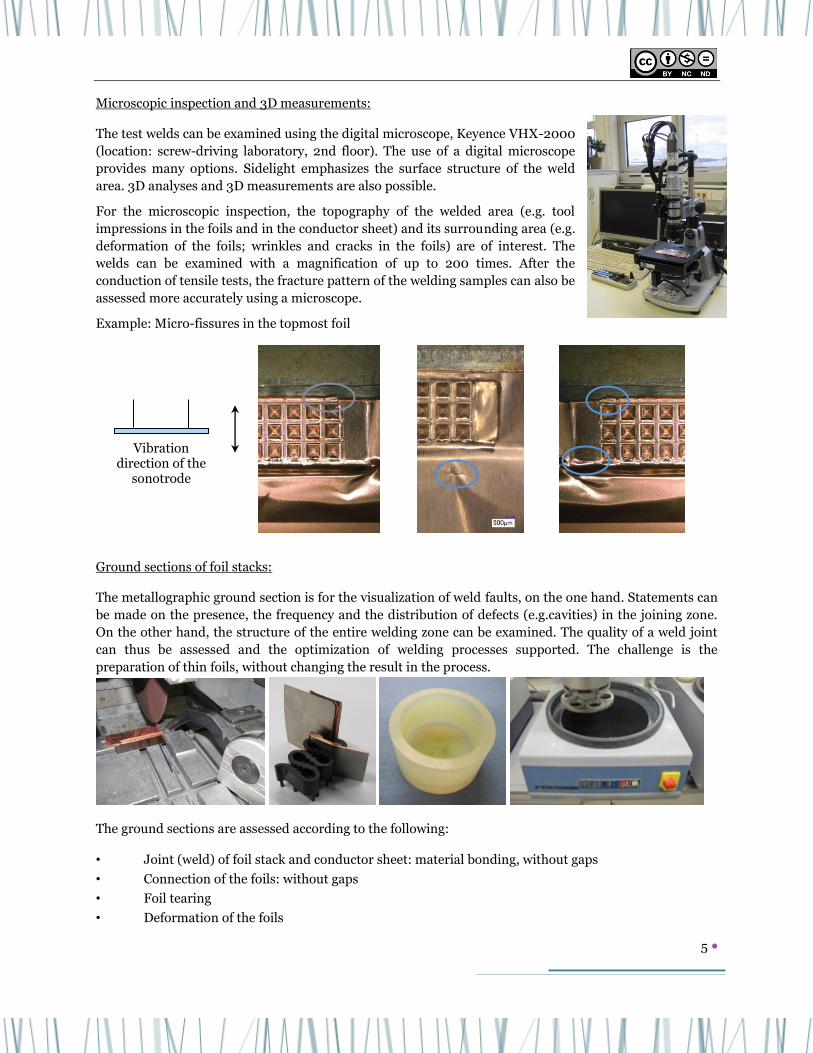
Microscopic inspection and 3D measurements:
The test welds can be examined using the digital microscope, Keyence VHX-2000
(location: screw-driving laboratory, 2nd floor). The use of a digital microscope
provides many options. Sidelight emphasizes the surface structure of the weld
area. 3D analyses and 3D measurements are also possible.
For the microscopic inspection, the topography of the welded area (e.g. tool
impressions in the foils and in the conductor sheet) and its surrounding area (e.g.
deformation of the foils; wrinkles and cracks in the foils) are of interest. The
welds can be examined with a magnification of up to 200 times. After the
conduction of tensile tests, the fracture pattern of the welding samples can also be
assessed more accurately using a microscope.
Example: Micro-fissures in the topmost foil
Ground sections of foil stacks:
The metallographic ground section is for the visualization of weld faults, on the one hand. Statements can
be made on the presence, the frequency and the distribution of defects (e.g.cavities) in the joining zone.
On the other hand, the structure of the entire welding zone can be examined. The quality of a weld joint
can thus be assessed and the optimization of welding processes supported. The challenge is the
preparation of thin foils, without changing the result in the process.
The ground sections are assessed according to the following:
• Joint (weld) of foil stack and conductor sheet: material bonding, without gaps
• Connection of the foils: without gaps
• Foil tearing
• Deformation of the foils
Vibration direction of the
sonotrode

6
• Thermal damage to the foils due to over-welding
• Forming of the weld nugget: geometry, structural change
Example from process development:
Development of Diagnostic Methods By observing the phenomena and characteristics during the welding process, relevant knowledge is to be
acquired for the application and a better comprehension of the process achieved. For these process
diagnoses, suitable methods are to be selected, tested for the specific process and applied.
Thermography provides information on the distribution of heat in the direct environment of the process.
It cannot look into the process.
The ultrasonic wave propagation in bodies can result
in heat developing due to movement and friction at
points where this is not intended. This can be detected
with this option. The following figure shows how a
point on the sonotrode heats up opposite the
component.
No joint, gap between foil stack and
conductor sheet
Foil tearing
Nickel layer of the
conductor damaged
Weld nugget
Weld nugget is separated by
cracks at this point

7
High-speed recording can be used to monitor the process excellently from the outside. A high-speed
camera is used for this. Due to high short shutter speed, a powerful light is required. The size of the
picture depends on the image frequency. If one selects an image frequency higher than a vibration
frequency of 20 kHz, the section becomes very small, but the individual vibrations can be followed. Larger
pictures provide a better overview of the situation.
The films show the development and flying away of particles, the sonotrode penetrating the stack and
possibly the separation of the topmost foils, and the surging and tearing of the foils. One can also see that
sticky material can be forced out of the joint, which then represents tinsel.

8
Piercing attempts during the recording of the vibrations revealed that the sonotrode could become
stationary and the vibration generators have an effect on the anvil. For this, a clearance-free system was
created for non-contact distance measurement.
Example: Data record for Samples Ultrasonic Weld. There can be seen a basic oscillation. The shift is due
to the lowering of the sonotrode. A chance in the amplitude is the welding oscillation itself.

9
Further Development of the Ultrasonic Welding Process To ensure a sufficient and reproducible supply of samples with foil stacks for the basic tests, a foil winding
device has been designed and built. In particular, the constantly good clean condition of the foils before
winding was aimed at. A cleaning module was developed for this purpose, for removing dirt in the form of
grease layers, oil residue and loosely adhering particles. The cleaning effect is essentially achieved by the
continuous application of ethanol, followed by the separation of the residue dissolved in the ethanol on a
microfiber cloth.
Two welding machine manufacturers were examined: Telsonic and Branson
Ultrasonic welding machines, UW20LHP/Versagraphix and M4000/SG22-x/MPS4
Welding stations were set up around them:
Ethanol cylinder
Wind-up unit
Quantity counter
Copper roll
Cleaning system
Deflection roller
10
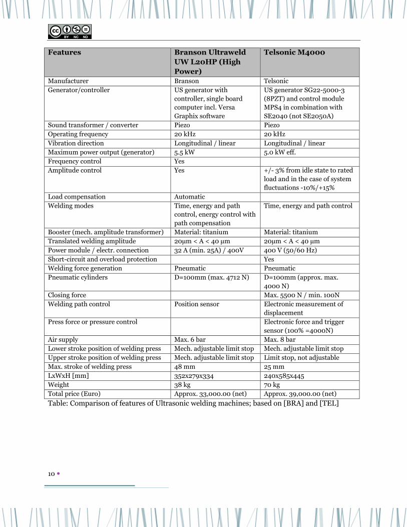
Features Branson Ultraweld
UW L20HP (High
Power)
Telsonic M4000
Manufacturer Branson Telsonic
Generator/controller US generator with
controller, single board
computer incl. Versa
Graphix software
US generator SG22-5000-3
(8PZT) and control module
MPS4 in combination with
SE2040 (not SE2050A)
Sound transformer / converter Piezo Piezo
Operating frequency 20 kHz 20 kHz
Vibration direction Longitudinal / linear Longitudinal / linear
Maximum power output (generator) 5.5 kW 5.0 kW eff.
Frequency control Yes
Amplitude control Yes +/- 3% from idle state to rated
load and in the case of system
fluctuations -10%/+15%
Load compensation Automatic
Welding modes Time, energy and path
control, energy control with
path compensation
Time, energy and path control
Booster (mech. amplitude transformer) Material: titanium Material: titanium
Translated welding amplitude 20µm < A < 40 µm 20µm < A < 40 µm
Power module / electr. connection 32 A (min. 25A) / 400V 400 V (50/60 Hz)
Short-circuit and overload protection Yes
Welding force generation Pneumatic Pneumatic
Pneumatic cylinders D=100mm (max. 4712 N) D=100mm (approx. max.
4000 N)
Closing force Max. 5500 N / min. 100N
Welding path control Position sensor Electronic measurement of
displacement
Press force or pressure control Electronic force and trigger
sensor (100% =4000N)
Air supply Max. 6 bar Max. 8 bar
Lower stroke position of welding press Mech. adjustable limit stop Mech. adjustable limit stop
Upper stroke position of welding press Mech. adjustable limit stop Limit stop, not adjustable
Max. stroke of welding press 48 mm 25 mm
LxWxH [mm] 352x279x334 240x585x445
Weight 38 kg 70 kg
Total price (Euro) Approx. 33,000.00 (net) Approx. 39,000.00 (net)
Table: Comparison of features of Ultrasonic welding machines; based on [BRA] and [TEL]
11
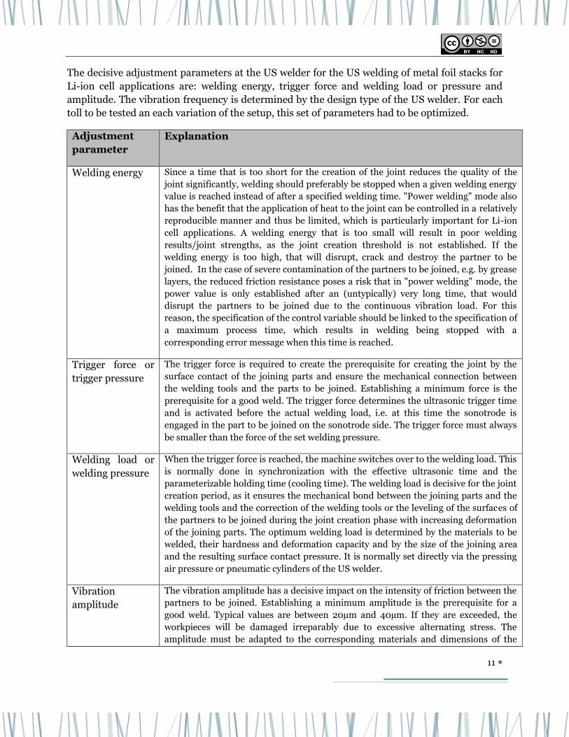
The decisive adjustment parameters at the US welder for the US welding of metal foil stacks for
Li-ion cell applications are: welding energy, trigger force and welding load or pressure and
amplitude. The vibration frequency is determined by the design type of the US welder. For each
toll to be tested an each variation of the setup, this set of parameters had to be optimized.
Adjustment
parameter
Explanation
Welding energy Since a time that is too short for the creation of the joint reduces the quality of the
joint significantly, welding should preferably be stopped when a given welding energy
value is reached instead of after a specified welding time. "Power welding" mode also
has the benefit that the application of heat to the joint can be controlled in a relatively
reproducible manner and thus be limited, which is particularly important for Li-ion
cell applications. A welding energy that is too small will result in poor welding
results/joint strengths, as the joint creation threshold is not established. If the
welding energy is too high, that will disrupt, crack and destroy the partner to be
joined. In the case of severe contamination of the partners to be joined, e.g. by grease
layers, the reduced friction resistance poses a risk that in "power welding" mode, the
power value is only established after an (untypically) very long time, that would
disrupt the partners to be joined due to the continuous vibration load. For this
reason, the specification of the control variable should be linked to the specification of
a maximum process time, which results in welding being stopped with a
corresponding error message when this time is reached.
Trigger force or
trigger pressure
The trigger force is required to create the prerequisite for creating the joint by the
surface contact of the joining parts and ensure the mechanical connection between
the welding tools and the parts to be joined. Establishing a minimum force is the
prerequisite for a good weld. The trigger force determines the ultrasonic trigger time
and is activated before the actual welding load, i.e. at this time the sonotrode is
engaged in the part to be joined on the sonotrode side. The trigger force must always
be smaller than the force of the set welding pressure.
Welding load or
welding pressure
When the trigger force is reached, the machine switches over to the welding load. This
is normally done in synchronization with the effective ultrasonic time and the
parameterizable holding time (cooling time). The welding load is decisive for the joint
creation period, as it ensures the mechanical bond between the joining parts and the
welding tools and the correction of the welding tools or the leveling of the surfaces of
the partners to be joined during the joint creation phase with increasing deformation
of the joining parts. The optimum welding load is determined by the materials to be
welded, their hardness and deformation capacity and by the size of the joining area
and the resulting surface contact pressure. It is normally set directly via the pressing
air pressure or pneumatic cylinders of the US welder.
Vibration
amplitude
The vibration amplitude has a decisive impact on the intensity of friction between the
partners to be joined. Establishing a minimum amplitude is the prerequisite for a
good weld. Typical values are between 20µm and 40µm. If they are exceeded, the
workpieces will be damaged irreparably due to excessive alternating stress. The
amplitude must be adapted to the corresponding materials and dimensions of the

12
parts to be joined.
Vibration
frequency
The vibration frequency is determined by the type of US welder. Machines with 20
kHz are used. For applications with very few metal foils, machines with a vibration
frequency of 40 kHz are also used.
Table: Adjustment parameters for US welding, based on [ADA]
The very precise investigations also revealed a previously unknown effect on the welding result, which was
not mentioned by the machine manufacturer. Based on the initially inexplicable deviations in the welding
quality, the Telsonic machine was examined in more detail.
The result was that the precise tightening torque between sonotrode and vibration system and the
condition and absence of oil on the contact areas are of special importance.
For this, a special torque wrench was built for the 100 Nm tightening torque, to achieve the necessary
reproducibility.
The clamping screws of the bearing rings must be tightened to 20 Nm.

13
The optimum tool shape was examined in great detail. It determines how to engage in the foil stack, how
the vibrations are transferred and to what loads the topmost foils in particular are exposed to. An aligned
pyramid shape has proven to be ideal. The alignment of the sonotrode and the anvil is also important,
however.
The original intention of welding one long seam in one go had to be abandoned, because the available
machine capacity is not sufficient. Therefore, four separate weld seams were planned.
0±0,1mm
0°±1°
Sonotrode
Amboss

14
In addition to the actual joint, the tool shape also has a significant influence. To avoid any deformation of
the foils, the intervention zone needed to be offset more.
The following settings and welding processes were determined. Both welding machines would be capable
for the process. Finally, the target process was developed with the machine with which there was the most
experience.
Parameter Copper welding Aluminum welding Amplitude 64%, 25.9 µm 50/20.0 µm Energy 430 Ws 250 Ws Welding pressure 1.35 bar 0.8 bar F Trigger 650 N 450 N Welding time 0.310 s 0.424 s
The optimized tools for both processes are the two-row pyramid chain for the sonotrode,
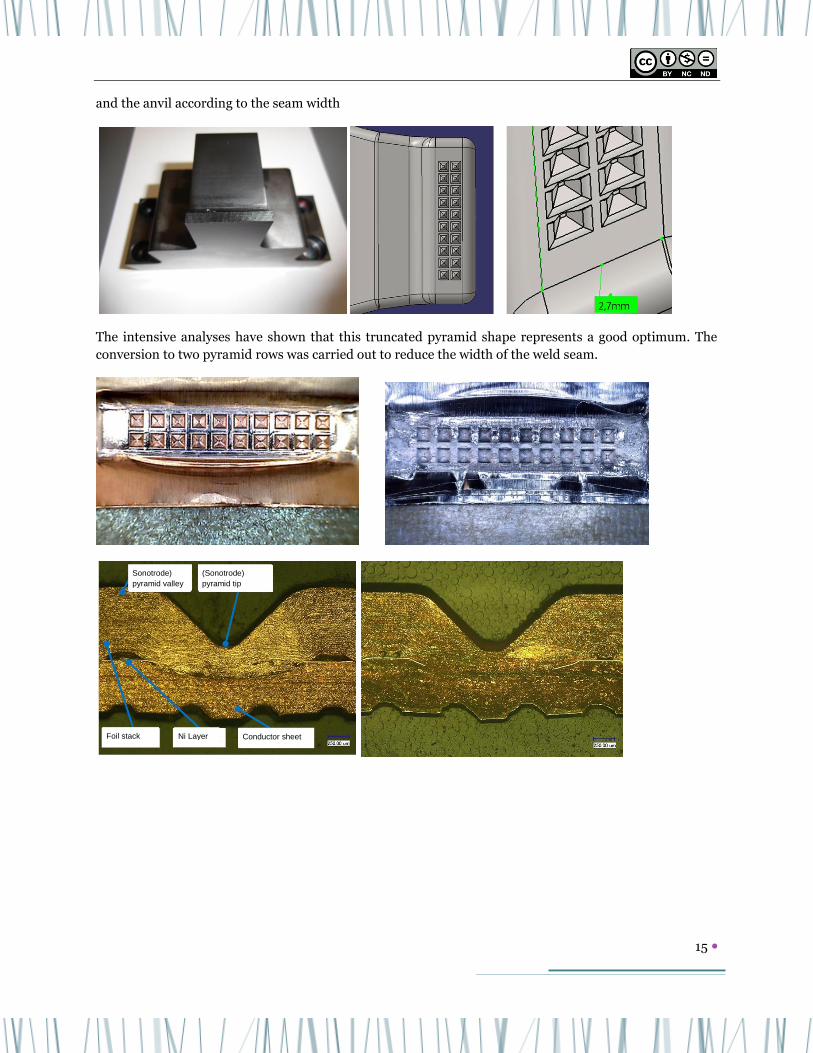
15
and the anvil according to the seam width
The intensive analyses have shown that this truncated pyramid shape represents a good optimum. The
conversion to two pyramid rows was carried out to reduce the width of the weld seam.
Sonotrode)
pyramid valley
(Sonotrode)
pyramid tip
Foil stack Ni Layer Conductor sheet

16
The process is also OK to a large extent in the event of deviations of the parameters. The different welding
depths and deformation of the component are to be seen
A minimum throat thickness of 2.7 mm was achieved. The result according to the following sketch is a
computational increase in the active area by
.
achieved:
welding area
137
311
137 + Δa
Starting point
12 x 5 a = 5 mm
2,7 x 14,5 a = 2,7 mm
Δa

17
Alternative Joining Methods Ultrasonic welding is very well suited for mixed aluminum and copper
compounds. In the case of compounds of the same type inside the cell,
other methods are also possible. A problem of laser welding is the
variety of surfaces and the air included in a stack. Resistance welding
would therefore appear to be more productive.
Research has shown that the flow of current in the foils can be
concentrated using studs. The tests were carried out with a 20 kHz
Matuschek system. The welding parameters are determined in the
standard manner in terms of force, current intensity and pulse time
without special considerations.
To achieve narrow welding zones (Elibama
requirement) an attempt is made to give them a
longitudinal shape.
An attempt was made first to create a longish stud by stamping, which was however flattened during the
process, i.e. a stud must be made out of the solid. Massive forming or chip removal would also be possible.
Wire pieces were placed underneath. They were melted into the underside.
A copper sheet with the copper foils could be welded onto the surface with foils. The stud is for
concentrating the current. The top electrode made of tungsten prevents the melt from escaping and seals
the joint.
A copper sheet with the copper foils could be welded onto the surface with foils. The stud is for
concentrating the current. The top electrode made of tungsten prevents the melt from escaping and seals
the joint.
conductor
stack

18
For aluminum, it was necessary to attach a sandwich cover sheet next to the stud to prevent the aluminum
from being welded onto the electrode. It could then be welded well, however. The surrounding solid
material prevents the melted mass from escaping. The individual foils are all well connected. There was
only a solidification cavity in the center of the weld nugget, which is not critical.
All tensile tests were above 300 N. These results mean that are is also a solution for joining pouch cells
with the reliable resistance welding method. However, the design requirements shown here must be
complied with.
Stacking Work Packages
Development of a Work piece Carrier and Clamping System The local clamping system in the direct vicinity of the processes for cutting the foil ends and joining the
conductors has a direct impact on dimensional accuracy and the joining quality.
Various different clamping principles are tested first, then a concept is developed:
It is important to clamp the foils next to the anvil and the sonotrode, but still to maintain sufficient
distance to the process in order that the foils can also vibrate during the process, without tearing.

19
The process chain at the joint consists of the steps: clamping, cutting, inserting the conductor and then
welding the conductors together with the foils. The workpiece carrier developed during the stacking WP
should be the basis. The requirements were stacking capability, not applying too much force to the
individual foils, the automatic firing of the carrier, good fastening of the foils to protect them from
slipping, protection of the foils and consistency through all process steps.
Branson US-Welding 5,5 kW
insert electrode sheet from stack
welding fixtureanvil and
sonotrode
shoe hold down
foil stack in integrated part carrier
Weld
Position
Electrode
Cutting
Joining Zone
clamped
Clamping Joining Zone
Clamping Stack
20
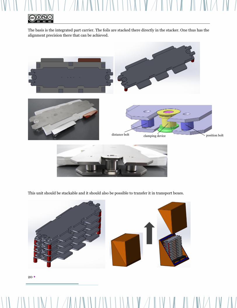
The basis is the integrated part carrier. The foils are stacked there directly in the stacker. One thus has the
alignment precision there that can be achieved.
This unit should be stackable and it should also be possible to transfer it in transport boxes.
position bolt distance bolt clamping device

21
For the positioning of the conductors, this unit must be inserted in a further carrier. The necessary
adjustment options for alignment are included.
This carrier itself is inserted in the individual stations in the corresponding process tables and aligned
with the adjustment screws enclosed for the cutting or joining process.
Cutting
Welding:
22
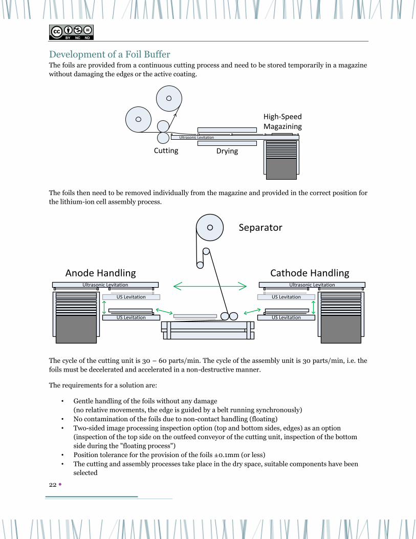
Development of a Foil Buffer The foils are provided from a continuous cutting process and need to be stored temporarily in a magazine
without damaging the edges or the active coating.
The foils then need to be removed individually from the magazine and provided in the correct position for
the lithium-ion cell assembly process.
The cycle of the cutting unit is 30 – 60 parts/min. The cycle of the assembly unit is 30 parts/min, i.e. the
foils must be decelerated and accelerated in a non-destructive manner.
The requirements for a solution are:
• Gentle handling of the foils without any damage
(no relative movements, the edge is guided by a belt running synchronously)
• No contamination of the foils due to non-contact handling (floating)
• Two-sided image processing inspection option (top and bottom sides, edges) as an option
(inspection of the top side on the outfeed conveyor of the cutting unit, inspection of the bottom
side during the "floating process")
• Position tolerance for the provision of the foils ±0.1mm (or less)
• The cutting and assembly processes take place in the dry space, suitable components have been
selected
Ultrasonic Levitation
DryingCutting
High-SpeedMagazining
Ultrasonic Levitation
US Levitation
US Levitation
Ultrasonic Levitation
US Levitation
US Levitation
Anode Handling Cathode Handling
Separator

23
• All process stations are easy to access manually for maintenance, process monitoring, tool
change, etc.
• Both the cutting process, as well as magazining, storage and provision can be carried out in a
controlled atmosphere (suitable enclosure and air ducting possible). A dry room atmosphere must
be kept as small as possible due to energy costs
Ultrasound-based floating from the semi-conductor technology should be used as the technology for non-
contact handling. The effective principle of the ultrasonic bearing is based on repulsion by the air
vibrations of the ultrasonic sonotrode. Holding from above is achieved by the application of a vacuum.
Many handling tasks require the simultaneous application of attractive and repellent forces, e.g. gripping
at the top. In these cases, the repellent effect of ultrasound is combined with attractive vacuum forces.
This technology enables the simple handling of workpieces, which corresponds to conventional gripping
at the top (with mechanical contact). In addition, flexible components can be smoothed without contact to
the handling tool, their geometry stabilized and held in position.
The test plant creating has an incoming conveyor for catching the cut foils to deposit them in the first
magazine. The second magazine serves as a demonstrator of the stacking device, in which the foils from
the first magazine are rearranged. In addition, there is a drop box for separating foils not okay. The
inspection with line scan cameras was not illustrated here. The feed motion is established by a small
driver, which does not damage the sensitive foil however, due to the air suspension.
Infeed conveyor,
corresponds to the
outlet of a cutting
device
Magazine 2 Magazine 1 Drop box

24
For the qualification of the process, the magazine prototype was made of aluminum. For the series
production process, a cost-effective alternative is to be developed, for example made of plastic, because a
large quantity is required to be able to buffer different output volumes. For the standard magazine, a
suitable enclosure is also to be taken into account for protection from environmental influences.
Magazine with foils inserted Magazine with elevated base in operating position
Development of a Comprehensive Plant Concept Before a new plant concept can be created, the various requirements need to be analyzed. Possible design
conflicts need to be revealed and a decision made for an optimum concept.
Dried electrode and separator materials are hygroscopic. It therefore needs to be ensured that after drying
the intermediate products, they are then only transferred and processed in defined climatic conditions.
These conditions are to be ensured in the rooms in which the dried intermediate products are processed
and transported. This does not only apply to the normal process, but also to process interruptions and
troubleshooting. If these conditions are not complied with, the intermediate products are to be marked as
not okay and removed, i.e. the drying of the intermediate products should take place as late as possible.
Individual process areas should be encapsulated to minimize rejects due to the violation of the climatic
conditions.
The working rooms for workers and the process rooms have different air conditions. Exhaled air impairs
the dry air condition and increases the dew point. Increased energy is necessary in order to retain a dry air
condition in the room. That means strictly separating the rooms for dried intermediate products and the
rooms in which the workers need to move. Dry room specific climatic conditions for these movement
areas should be as low as possible, and small, encapsulated process rooms provided to prevent too many
rejects in the event of manual fault elimination.

25
A dry air condition in the dry room must also be ensured in the event of malfunctions and downtimes. The
required climatic conditions must also be retained in the event of production downtimes if there are
intermediate products in the rooms for which air conditioning is required. Alternatively, the relevant
intermediate products are to be marked as not okay.
In particular the extraction of cutting dust requires high filter technology expenses (extraction of particles
versus dry room condition). These expenses will increase the higher the dew point is, due to the static
charge of the particles. The particle properties and the available filter technology can and do result in part
of the air flow being discharged via the roof after filtration. The higher the dew point of the process air is,
the more energy is required for the air to be supplied, i.e. cutting the materials and the extraction of the
particles should take place, if possible, before drying, and cleaning of the electrodes before drying, if
possible. Encapsulation and separate supply air for extraction at the separator intersection. Encapsulation
and separate supply air for extraction for cutting flags, encapsulation and separate supply air for
extraction during welding.
All plant components and conveyor systems in the production area should be encapsulated, due to the
high dryness requirements in the production process. For the atmosphere within the plant, the following
conditions are to be complied with. Compliance with the atmosphere within the plant modules has the
highest priority. Therefore, current plants are run with slight overpressure to ensure the required dew
point. (Intermediate) products may only be moved through the plant in the required atmosphere. If the
dew point is exceeded, the relevant intermediate products are to be marked as parts that are not okay and
removed. That cannot be avoided, in particular when eliminating malfunctions. Compartmentalization
concepts are to be applied to attempt to reduce the number of intermediate products that become not
okay parts.
In addition, the drying processes at the lines respond sensitively to plant downtimes and intermittent
processes, i.e. buffering is not only for increasing availability, but also for improving the quality. In
addition, the clamping concept developed above should be applied consistently.
The encapsulation should also be retained for the transport processes of all partial products. Manual
transport vehicles or automatically guided vehicles could be used between the stations. The atmosphere in
the transport container must be monitored. The stations must be equipped with removal systems for
loading and unloading in a dry atmosphere. The transport cycle times can be reduced if the stack
capability of e.g. 5 work piece carriers is exploited. At an estimated cycle time of 1 minute per stack, that
would be one transport operation every 5 minutes. The benefit of automatically guided vehicles is that
access to the systems is given simultaneously, and one does not have to cross conveyor belts that produce
dirt using stairs. No multipurpose tool magazines should be provided in the stations, as that would only
increase their complexity. A fast change of the magazines is more efficient. The complete parallelization of
the station is to be preferred.
It would appear to be practical for the Z folder to roll up the material again after drying for decoupling.
Discontinuities in the separator should be possible in the Z folder by automatically removing a double
layer. With a pick and place system, that would be the removal of a sheet. The electrode sheets should be
cut first and only then dried.
In addition, the complete data relating to everything that occurs in the system and all process steps needs
to be recorded. All workpiece carriers, magazines and rolls are to be equipped with ID technology and the
stations with readers in order that everything can be traced.

26
A view of the integrated overall concept is given below.
Separator unwinding, drying and rewinding
NIO-Stacks,
Consumables
Deflectors,
Adhesive Strips,
Consumables
in clean dry airlock
Dry Separator CoilSeparator
Coil
Cathode Coil Cathode Waste in
medium dry airlookNIO-Cathodes
Anode Coil Anode Waste NIO-Anodes
Stacked Stacks
Loca
tin
g
Sta
ckin
g/ Z
-Fo
ldin
g
↔
↔↔
↔↔
↔↔
↔↔
↔↔
↔↔↔
↔↔
↔↔↔↔↔
↔↔↔↔↔
↔
↔↔↔↔↔
↔↔↔↔↔
↔↔↔↔↔
↔
Separator-
Coils
Cla
mp
ing, C
utt
ing,
Jo
inin
g, W
eld
ing
Taped
Deflectors
Ta
pin
g
De
fle
cto
rs
Ta
pin
g.
idn
tify
ing
Sta
cks
Insp
ectio
n
Insertion into
PouchAGVs with extra dry boxes
Clean dry room
Anode unwinding, cutting, drying and deposit in magazins
Cathode unwinding, cutting, drying and deposit in magazins
Airlocks not shown
Unpacking in
medium clean
medium dry
airlock
WasteMaterial with residual moistureDryerDry materialTransfer store

27
Production of Demonstrators
The designed stations have been manufactured and assembled. By producing demonstrators the concept
could be verified.
The taped stack were taken from series production and entered into the work piece carrier. The position
was aligned by mechanical corners. In series production the accuracy would derive out of the z-folder. The
closing lid of the workpiece carrier and the clips are designed to be automated.
The concept to be able to measure the stack dimensions uses a light barrier with referenced edges of the
fixture.
The clamping blades are part of the 2nd carrier are lowered and it can be transferred into the cutting
station.

28
After inserting and clamping the conductors the unit is be transferred into the welding station. Shifting to
the side positions it according to the seam positions.
The build demonstrator:
References
[DVS 2216-1] DVS 2216-1 Ultraschallschweißen von Kunststoffserienteilen –
Prozessbeschreibung, Maschinen und Geräte, Einflussgrößen, Konstruktion,
Qualitätssicherung

29
[DVS 2230-1] DVS 2230-1 Schweißen von Kunststoffserienteilen - Qualitätssicherung,
Prüfung
[BRA] Produktinformation Fa. Branson Ultraschall
[TEL] Produktinformation Fa. Telsonic Ultraschall
[STE] Internet-Auftritt der Fa. Steckmann Ultrasonics
[ADA] Adam, Tino; Dissertation „Ultraschallschweißen ausgewählter
Aluminiumlegierungen mit erhöhter Festigkeit“; Otto-von-Guericke-Universität
Magdeburg, Fakultät für Maschinenbau, Institut für Füge- und Strahltechnik
(1999)
Contact
DAIMLER: Dirk LINDENAU
The ELIBAMA project is granted by the European Commission under the “Nanosciences,
nanotechnologies, materials & new production technologies” (NMP) Themeof the 7th
Framework Programme for Research and Technological Development.


