NIPPON STEEL TECHNICAL REPORT No. 89 JANUARY 2004 - 68 - UDC 621 . 318. 4 : 537 . 84 Electromagnetic Coil Designed by Magneto-Hydro-Dynamic-Simulation Ken YOKOTA* 1 Keisuke FUJISAKI* 1 Abstract Linear induction motor type In-Mold Electro-Magnetic Stirrer “M-EMS” is equipped in most of the slab continuous caster in Nippon Steel Corp. to improve slab surface quality by stirring the molten steel flow. To satisfy the customer’s permanent demand for high quality steel, the molten steel flow patterns in the casting mold, which reflects on the steel quality deeply, must be clarified and the flow control must be optimized against each casting conditions. Authors are carrying out “Electro- magnetic process solution” in the casting field by applying Magneto-Hydro-Dynamic simulation to the molten steel flow process in order to evaluate and clarify quantita- tively, and finally to control. In this paper, the established specification designing method using Magneto-Hydro-Dynamic simulation for M-EMS and other electro- magnetic coils is shown. * 1 Environment & Process Technology Center 1. Introduction Nippon Steel developed an In-Mold Electromagnetic Stirrer, here- inafter abbreviated to “M-EMS”, a linear induction type motor, to control molten steel flow in the casting mold of a continuous caster, hereinafter abbreviated to CC, in order to improve slab surface qual- ity. The first M-EMS was installed at Hirohata Ironworks in 1980 1-2) , and later in 1982, the second machine was installed at Oita Iron- works. After these two cases, Nippon Steel continued improving and equipping the M-EMS to the main CCs in other Ironworks 3-5) . M-EMS aims at giving a uniform flow to the front of the solidi- fied shell of a slab surface throughout the entire width direction in terms of space and time by applying electromagnetic force. It is re- ported that giving a uniform flow has result in controlling the disper- sion of the molten steel temperature distribution, reducing the occur- rence of solidification delay and improving the uniformity of the dispersion in shell thickness 6) . To satisfy the customer’s permanent demand for high quality steel, however, it is necessary to clarify molten flow patterns in the casting mold, which greatly reflects on steel quality, as well as to control the flow by optimizing the electromagnetic force applied for each cast- ing conditions. Based on these viewpoints, the authors are carrying out with the “electromagnetic process solution” in the casting field by applying magneto-hydro-dynamic simulation to evaluate and clarify quanti- tatively the flow patterns in the casting mold, such as the stream from the submerged nozzle and stirred flow by electromagnetic force, in order to control the molten steel flow. This paper reports on the establishment of the technique of de- signing molten steel flow control actuators, such as M-EMS and other electromagnetic coils, by the application of magneto-hydro-dynamic simulation. 2. Outline of the In-Mold Electro-Magnetic Stirrer : M-EMS As Fig. 1 shows, M-EMS is composed of a pair of induction type linear motors with each mounted opposite to the upper part of the backside of each casting mold. The linear motors move the magnetic fields opposite to each other. More specifically, the direction of the AC phase applied to the copper coils, lined up sidelong, attached to the iron core is controlled. In the molten steel, a new magnetic field is generated as a counter field in the direction of the moving mag-
Transcript
NIPPON STEEL TECHNICAL REPORT No. 89 JANUARY 2004
- 68 -
UDC 621 . 318. 4 : 537 . 84
Electromagnetic Coil Designed byMagneto-Hydro-Dynamic-Simulation
Ken YOKOTA*1 Keisuke FUJISAKI*1
Abstract
Linear induction motor type In-Mold Electro-Magnetic Stirrer “M-EMS” is
equipped in most of the slab continuous caster in Nippon Steel Corp. to improve slab
surface quality by stirring the molten steel flow. To satisfy the customer’s permanent
demand for high quality steel, the molten steel flow patterns in the casting mold,
which reflects on the steel quality deeply, must be clarified and the flow control must
be optimized against each casting conditions. Authors are carrying out “Electro-
magnetic process solution” in the casting field by applying Magneto-Hydro-Dynamic
simulation to the molten steel flow process in order to evaluate and clarify quantita-
tively, and finally to control. In this paper, the established specification designing
method using Magneto-Hydro-Dynamic simulation for M-EMS and other electro-
magnetic coils is shown.
*1 Environment & Process Technology Center
1. IntroductionNippon Steel developed an In-Mold Electromagnetic Stirrer, here-
inafter abbreviated to “M-EMS”, a linear induction type motor, tocontrol molten steel flow in the casting mold of a continuous caster,hereinafter abbreviated to CC, in order to improve slab surface qual-ity. The first M-EMS was installed at Hirohata Ironworks in 19801-2),and later in 1982, the second machine was installed at Oita Iron-works. After these two cases, Nippon Steel continued improving andequipping the M-EMS to the main CCs in other Ironworks3-5).
M-EMS aims at giving a uniform flow to the front of the solidi-fied shell of a slab surface throughout the entire width direction interms of space and time by applying electromagnetic force. It is re-ported that giving a uniform flow has result in controlling the disper-sion of the molten steel temperature distribution, reducing the occur-rence of solidification delay and improving the uniformity of thedispersion in shell thickness6).
To satisfy the customer’s permanent demand for high quality steel,however, it is necessary to clarify molten flow patterns in the castingmold, which greatly reflects on steel quality, as well as to control theflow by optimizing the electromagnetic force applied for each cast-
ing conditions.Based on these viewpoints, the authors are carrying out with the
“electromagnetic process solution” in the casting field by applyingmagneto-hydro-dynamic simulation to evaluate and clarify quanti-tatively the flow patterns in the casting mold, such as the streamfrom the submerged nozzle and stirred flow by electromagnetic force,in order to control the molten steel flow.
This paper reports on the establishment of the technique of de-signing molten steel flow control actuators, such as M-EMS and otherelectromagnetic coils, by the application of magneto-hydro-dynamicsimulation.
2. Outline of the In-Mold Electro-Magnetic Stirrer :M-EMSAs Fig. 1 shows, M-EMS is composed of a pair of induction type
linear motors with each mounted opposite to the upper part of thebackside of each casting mold. The linear motors move the magneticfields opposite to each other. More specifically, the direction of theAC phase applied to the copper coils, lined up sidelong, attached tothe iron core is controlled. In the molten steel, a new magnetic fieldis generated as a counter field in the direction of the moving mag-
NIPPON STEEL TECHNICAL REPORT No. 89 JANUARY 2004
- 69 -
netic field, and another new magnetic field is also generated to retainthe moving magnetic field on the opposite side. The generation of amagnetic field accompanies an eddy current, and the outer productof the magnetic field and eddy current vector in the molten steelcauses the electromagnetic force generally called Lorentz force. Theelectromagnetic force vector is distributed circle-wise when viewedabove from the molten steel, and in the vicinity of the casting moldwall it works largely in the same direction with the moving magneticfield generated by the controlled coil current. The molten steel isstirred by this force.
The molten steel flow in the casting mold is mainly put under thecontrol of the stream from the submerged nozzle and the electro-magnetic force of the M-EMS. The distribution of the nozzle streamdepends mostly on the casting conditions, such as casting width andcasting rate, and the shape of the nozzle. In the present-day, how-ever, the casting width and rate are varied during casting to enhanceproductivity in standard CC operation. Therefore the nozzle streamdistribution is considered to be varied not only by phenomena, suchas nozzle clogging, that tend to occur over the casting time, but alsoby standard CC operation.
Accordingly, the M-EMS plays a great role as a controllable ac-tuator that gives a stable flow to the front of the solidified shell, thecharacteristics and specification design as a linear motor becomesimportant.
3. Technique of Designing M-EMS by the Applica-tion of Electro-Magneto-Hydro-Dynamic Simula-tionThis chapter shows the flowchart of the specification design of
M-EMS after summarizing the techniques of hydrodynamic simula-tion and electromagnetic field analysis that compose magneto hy-drodynamic simulation. Note that the explanation of the symbolsdealt with in this chapter is described in Section 3.1.3.3.1 Outline of magneto hydrodynamic simulation technique
In the molten steel stirred by M-EMS, multi physics, such asfluid dynamics, solidification phenomena due to heat transfer andelectromagnetic field affect each other in a complicated manner inthe mold as short as 1 m. It is not realistic even today when computertechnology is making dramatic advancements, however, to simulatecoupled multi-physical phenomena in numerical analysis strictly.Therefore, in this paper the molten steel flow and the electromag-netic force affected are taken into consideration in the technique ofmagneto-hydro-dynamic simulation in terms of controlling the mol-
ten steel flow in the casting mold7).3.1.1 Fluid dynamic analysis
Fluid dynamic analysis uses the finite difference method for so-lution, and the continuous equation of flow and Navier-Stokes equa-tion as the basic equation.
0 = ∇ ⋅ U (1)
∂U∂t + U ⋅ ∇U = − ∇P
ρ + g + Fρ + ∇ ⋅ ν∇U (2)
Molten steel is treated as incompressible (constant density). Theelectromagnetic force by M-EMS is added to the third member ofthe right side of equation (2). LES (large eddy simulation) was adoptedas a model that enables high accuracy calculation of turbulent flow,an unsteady flow quickly changing over time, mainly to expressnozzle stream fluctuation. Simultaneous solution of equations (1)and (2) enables to obtain the flow pattern on which M-EMS-gener-ated electromagnetic force worked.3.1.2 Electromagnetic field analysis
The basic equation of the electromagnetic field is well known asMaxwell equation8). This section shows Maxwell equation and theequation of calculating the electromagnetic force in which variablesare reduced by A-φ method using the magnetic vector potential in-stead of treating Maxwell equation directly. References should bereferred to concerning the method of derivation9).
∇ × 1µ ∇ × A + σ ∂A
∂t + ∇φ = Jo (3)
F = σ ∂A
∂t + ∇φ × ∇ × A(4)
The solution of equation (3) enables to obtain the distribution ofmagnetic flux density in the iron core or molten steel as well as theheating values of the casting mold from the distribution of the eddycurrent induced electromagnetically. As regards the conductivity ofthe model necessary for the solution of equations (3) and (4), itsconcrete value is derived from the references along with its tempera-ture characteristics10). The conductivity is treated as a stationary valueon the assumption that it is temperature-constant.
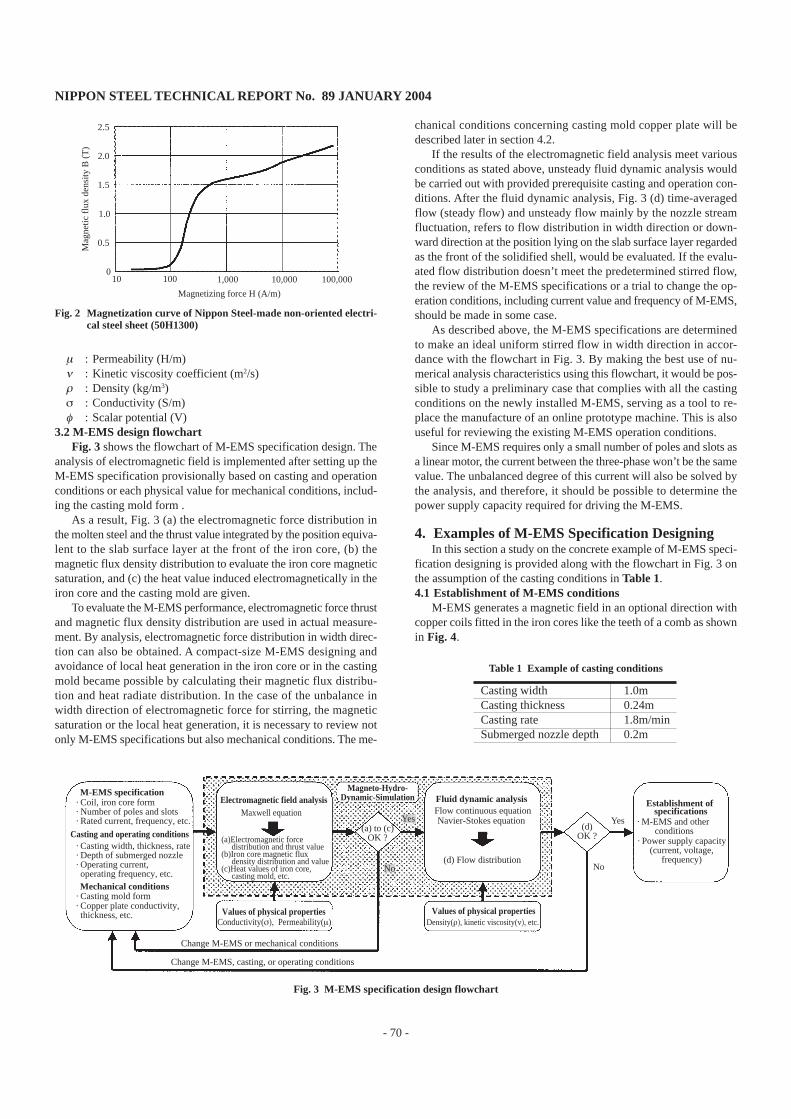
On the other hand, as regards the relative permeability, copperplate and stainless steel plate members which compose the castingmold, and the molten steel far in excess of Curie point temperaturemay be regarded as 1, same as in a vacuum. However, the iron core,a major component of M-EMS, is laminated by electrical steel sheets,same as a rotating type motor, shows nonlinear characteristics againstmagnetizing force.
In the actual M-EMS, non-oriented electrical steel sheets madeby Nippon Steel are used for iron core members. The logic referringto their magnetization characteristics is incorporated for analysis,resulting in highly accurate analytical findings. Fig. 2 shows the mag-netization curve used11).3.1.3 Symbols
The symbols indicated in bold letters are three-component vec-tors spatially.
A : Vector potential against magnetic flux density (Wb/m)F : Electromagnetic force (N/m3)g : Gravitational acceleration (m/s2)J
o: (Forced) current density (A/m2)
P : Pressure (Pa)t : Time (s)U : Rate of flow (m/s)
3.2 M-EMS design flowchartFig. 3 shows the flowchart of M-EMS specification design. The
analysis of electromagnetic field is implemented after setting up theM-EMS specification provisionally based on casting and operationconditions or each physical value for mechanical conditions, includ-ing the casting mold form .
As a result, Fig. 3 (a) the electromagnetic force distribution inthe molten steel and the thrust value integrated by the position equiva-lent to the slab surface layer at the front of the iron core, (b) themagnetic flux density distribution to evaluate the iron core magneticsaturation, and (c) the heat value induced electromagnetically in theiron core and the casting mold are given.
To evaluate the M-EMS performance, electromagnetic force thrustand magnetic flux density distribution are used in actual measure-ment. By analysis, electromagnetic force distribution in width direc-tion can also be obtained. A compact-size M-EMS designing andavoidance of local heat generation in the iron core or in the castingmold became possible by calculating their magnetic flux distribu-tion and heat radiate distribution. In the case of the unbalance inwidth direction of electromagnetic force for stirring, the magneticsaturation or the local heat generation, it is necessary to review notonly M-EMS specifications but also mechanical conditions. The me-
chanical conditions concerning casting mold copper plate will bedescribed later in section 4.2.
If the results of the electromagnetic field analysis meet variousconditions as stated above, unsteady fluid dynamic analysis wouldbe carried out with provided prerequisite casting and operation con-ditions. After the fluid dynamic analysis, Fig. 3 (d) time-averagedflow (steady flow) and unsteady flow mainly by the nozzle streamfluctuation, refers to flow distribution in width direction or down-ward direction at the position lying on the slab surface layer regardedas the front of the solidified shell, would be evaluated. If the evalu-ated flow distribution doesn’t meet the predetermined stirred flow,the review of the M-EMS specifications or a trial to change the op-eration conditions, including current value and frequency of M-EMS,should be made in some case.
As described above, the M-EMS specifications are determinedto make an ideal uniform stirred flow in width direction in accor-dance with the flowchart in Fig. 3. By making the best use of nu-merical analysis characteristics using this flowchart, it would be pos-sible to study a preliminary case that complies with all the castingconditions on the newly installed M-EMS, serving as a tool to re-place the manufacture of an online prototype machine. This is alsouseful for reviewing the existing M-EMS operation conditions.
Since M-EMS requires only a small number of poles and slots asa linear motor, the current between the three-phase won’t be the samevalue. The unbalanced degree of this current will also be solved bythe analysis, and therefore, it should be possible to determine thepower supply capacity required for driving the M-EMS.
4. Examples of M-EMS Specification DesigningIn this section a study on the concrete example of M-EMS speci-
fication designing is provided along with the flowchart in Fig. 3 onthe assumption of the casting conditions in Table 1.4.1 Establishment of M-EMS conditions
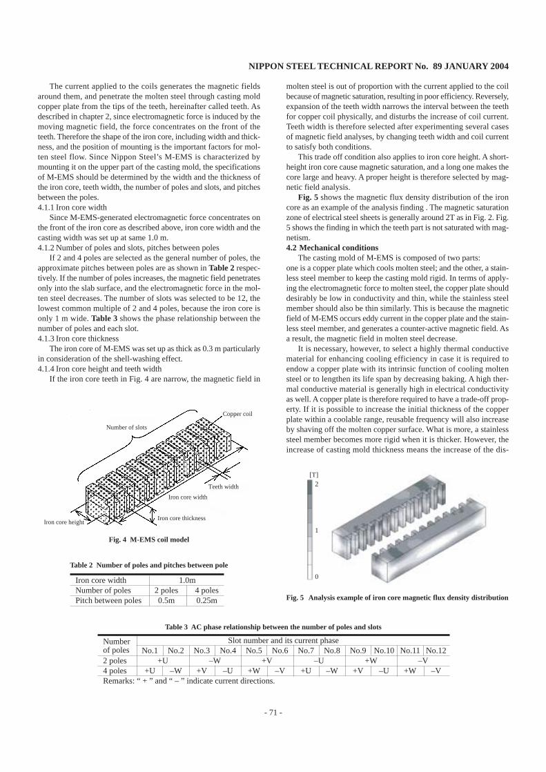
M-EMS generates a magnetic field in an optional direction withcopper coils fitted in the iron cores like the teeth of a comb as shownin Fig. 4.
M-EMS specification· Coil, iron core form· Number of poles and slots · Rated current, frequency, etc.
Casting and operating conditions· Casting width, thickness, rate· Depth of submerged nozzle· Operating current, operating frequency, etc.Mechanical conditions
· Casting mold form· Copper plate conductivity, thickness, etc.
Conductivity(σ), Permeability(µ)
Magneto-Hydro-Dynamic-SimulationElectromagnetic field analysis
Maxwell equation
(a)Electromagnetic force distribution and thrust value(b)Iron core magnetic flux density distribution and value(c)Heat values of iron core, casting mold, etc.
The current applied to the coils generates the magnetic fieldsaround them, and penetrate the molten steel through casting moldcopper plate from the tips of the teeth, hereinafter called teeth. Asdescribed in chapter 2, since electromagnetic force is induced by themoving magnetic field, the force concentrates on the front of theteeth. Therefore the shape of the iron core, including width and thick-ness, and the position of mounting is the important factors for mol-ten steel flow. Since Nippon Steel’s M-EMS is characterized bymounting it on the upper part of the casting mold, the specificationsof M-EMS should be determined by the width and the thickness ofthe iron core, teeth width, the number of poles and slots, and pitchesbetween the poles.4.1.1 Iron core width
Since M-EMS-generated electromagnetic force concentrates onthe front of the iron core as described above, iron core width and thecasting width was set up at same 1.0 m.4.1.2 Number of poles and slots, pitches between poles
If 2 and 4 poles are selected as the general number of poles, theapproximate pitches between poles are as shown in Table 2 respec-tively. If the number of poles increases, the magnetic field penetratesonly into the slab surface, and the electromagnetic force in the mol-ten steel decreases. The number of slots was selected to be 12, thelowest common multiple of 2 and 4 poles, because the iron core isonly 1 m wide. Table 3 shows the phase relationship between thenumber of poles and each slot.4.1.3 Iron core thickness
The iron core of M-EMS was set up as thick as 0.3 m particularlyin consideration of the shell-washing effect.4.1.4 Iron core height and teeth width
If the iron core teeth in Fig. 4 are narrow, the magnetic field in
molten steel is out of proportion with the current applied to the coilbecause of magnetic saturation, resulting in poor efficiency. Reversely,expansion of the teeth width narrows the interval between the teethfor copper coil physically, and disturbs the increase of coil current.Teeth width is therefore selected after experimenting several casesof magnetic field analyses, by changing teeth width and coil currentto satisfy both conditions.
This trade off condition also applies to iron core height. A short-height iron core cause magnetic saturation, and a long one makes thecore large and heavy. A proper height is therefore selected by mag-netic field analysis.
Fig. 5 shows the magnetic flux density distribution of the ironcore as an example of the analysis finding . The magnetic saturationzone of electrical steel sheets is generally around 2T as in Fig. 2. Fig.5 shows the finding in which the teeth part is not saturated with mag-netism.4.2 Mechanical conditions
The casting mold of M-EMS is composed of two parts:one is a copper plate which cools molten steel; and the other, a stain-less steel member to keep the casting mold rigid. In terms of apply-ing the electromagnetic force to molten steel, the copper plate shoulddesirably be low in conductivity and thin, while the stainless steelmember should also be thin similarly. This is because the magneticfield of M-EMS occurs eddy current in the copper plate and the stain-less steel member, and generates a counter-active magnetic field. Asa result, the magnetic field in molten steel decrease.
It is necessary, however, to select a highly thermal conductivematerial for enhancing cooling efficiency in case it is required toendow a copper plate with its intrinsic function of cooling moltensteel or to lengthen its life span by decreasing baking. A high ther-mal conductive material is generally high in electrical conductivityas well. A copper plate is therefore required to have a trade-off prop-erty. If it is possible to increase the initial thickness of the copperplate within a coolable range, reusable frequency will also increaseby shaving off the molten copper surface. What is more, a stainlesssteel member becomes more rigid when it is thicker. However, theincrease of casting mold thickness means the increase of the dis-
Iron core width 1.0mNumber of poles 2 poles 4 polesPitch between poles 0.5m 0.25m
Table 2 Number of poles and pitches between pole
Number Slot number and its current phaseof poles No.1 No.2 No.3 No.4 No.5 No.6 No.7 No.8 No.9 No.10 No.11 No.122 poles +U –W +V –U +W –V4 poles +U –W +V –U +W –V +U –W +V –U +W –VRemarks: “ + ” and “ – ” indicate current directions.
Table 3 AC phase relationship between the number of poles and slots
2
1
0
[T]
Fig. 5 Analysis example of iron core magnetic flux density distribution
Number of slots
Copper coil
Teeth width
Iron core width
Iron core thicknessIron core height
Fig. 4 M-EMS coil model
NIPPON STEEL TECHNICAL REPORT No. 89 JANUARY 2004
- 72 -
tance between iron core teeth and molten steel, and decreases theelectromagnetic force.
The foregoing contents are summarized in Fig. 6. At Nippon Steel,a copper plate conductivity, casting mold thickness and mold formare decided by using the analyses of the electromagnetic field andheat transfer. The analyses are used together to solve the trade-offconditions required for casting mold as expressed in Fig. 6. The analy-sis of heat transfer should be referred to the literature5).4.3 Electromagnetic field analysis
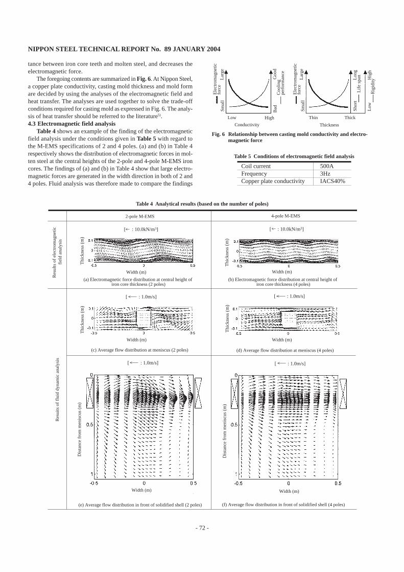
Table 4 shows an example of the finding of the electromagneticfield analysis under the conditions given in Table 5 with regard tothe M-EMS specifications of 2 and 4 poles. (a) and (b) in Table 4respectively shows the distribution of electromagnetic forces in mol-ten steel at the central heights of the 2-pole and 4-pole M-EMS ironcores. The findings of (a) and (b) in Table 4 show that large electro-magnetic forces are generated in the width direction in both of 2 and4 poles. Fluid analysis was therefore made to compare the findings
Coil current 500AFrequency 3HzCopper plate conductivity IACS40%
Table 5 Conditions of electromagnetic field analysis
2-pole M-EMS 4-pole M-EMS
[ : 10.0kN/m3]
(a) Electromagnetic force distribution at central height of iron core thickness (2 poles)
(b) Electromagnetic force distribution at central height of iron core thickness (4 poles)
[ : 10.0kN/m3]
[ : 1.0m/s]
(c) Average flow distribution at meniscus (2 poles)
[ : 1.0m/s]
(d) Average flow distribution at meniscus (4 poles)
[ : 1.0m/s]
(e) Average flow distribution in front of solidified shell (2 poles)
[ : 1.0m/s]
(f) Average flow distribution in front of solidified shell (4 poles)
Res
ults
of
elec
trom
agne
tic
fiel
d an
alys
isR
esui
ts o
f fl
uid
dyna
mic
ana
lysi
s
Width (m) Width (m)
Width (m)Width (m)
Thi
ckne
ss (
m)
Thi
ckne
ss (
m)
Thi
ckne
ss (
m)
Thi
ckne
ss (
m)
Width (m) Width (m)
Dis
tanc
e fr
om m
enis
cus
(m)
Dis
tanc
e fr
om m
enis
cus
(m)
Table 4 Analytical results (based on the number of poles)
Ele
ctro
mag
netic
fo
rce
Ele
ctro
mag
netic
fo
rce
Coo
ling
perf
orm
ance
Lif
e sp
an
Rig
idity
Low
Hig
h
Low High
Smal
lL
arge
Smal
lL
arge
Shor
tL
ong
Bad
Goo
d
Thin Thick
Conductivity Thickness
Fig. 6 Relationship between casting mold conductivity and electro-magnetic force
NIPPON STEEL TECHNICAL REPORT No. 89 JANUARY 2004
- 73 -
on the assumption that no problem is posed to the magnetic satura-tion and heat value of the iron core.4.4 Fluid dynamic analysis
Before applying electromagnetic force, fluid dynamic analysiswas made under the conditions given in Table 1 to obtain the findingof calculation representing the flow of a nozzle stream. Later, analy-sis is made in the state nearly equal to the actual CC operation byapplying electromagnetic force. (c) to (f) in Table 4 shows the find-ings of fluid dynamic analysis after applying electromagnetic force,and are the 60-second time-averaged flow distribution at the menis-cus and at the front of the solidified shell with the arrows represent-ing flow rate vectors.
The evaluation of the flow distribution and the M-EMS specifi-cations suitable for the casting conditions assumed in Table 1 basedon the findings of evaluation is shown below.4.4.1 Evaluation with flow distribution
The stirring force rotates counter clockwise at the cross sectionof the meniscus, and works from left to right at the front of the so-lidified shell. In 2-pole M-EMS in Table 4 (e), the stirred flow goesdown from 1/4 width without forming a uniform flow in width di-rection. This phenomenon can be confirmed also by the vector turn-ing over at the meniscus in the flow distribution in Table 4 (c). Theflow that had gone down pushed up to the meniscus after striking theshort side mold, and flowed in the direction opposite to that of stir-ring, thus obstructing stirring. Such a turn over flow ends up in form-ing a stagnant area with no flow by struggling with the stirred flow,possibly causing nonmetal inclusions and air bubbles entrapped bythe solidifying shell.
On the contrary, a uniform flow was given almost in width direc-tion at the M-EMS installed height in case of 4-pole M-EMS in Table4 (f). Also in Table 4 (d), a stirred flow is formed along the wall tomeet our expectation of high cleanability.4.4.2 M-EMS specifications suitable for provisional casting condi-
tionsAs a result of the study of designing the M-EMS specifications
based on the flowchart in Fig. 3 as described above, the suitablespecifications for provisional casting conditions are summarized inTable 6.
5. Technique of Designing Level DC Magnetic FieldIn this section the technique of designing the level DC magnetic
field, hereinafter abbreviated to LMF, is described. LMF has effec-tive for enhancing the quality inside the slab by controlling down-ward flow.
Fig. 7 shows the schematic drawing of LMF. The casting mold isplaced between the magnetic poles, and the level DC magnetic fieldis applied to the thickness direction. The structural member aroundthe casting mold also works as a yoke in the path of the magneticfield.
Since LMF is a DC electromagnet, eddy current won’t be in-duced in it’s static magnetic field and the M-EMS specifications de-sign flowchart in Fig. 3 can also be applicable to LMF and its pro-cess designing by adopting the following equation, with the 2nd mem-ber in the left side of equation (3) removed:
∇ × 1µ ∇ × A = Jo (5)
Main points of LMF designing are follows:(1)To evaluate the level of magnetic flux density required for con-
trolling downward molten steel flow.(2)To determine the coil current and the number of turns necessary
for generating required magnetic flux density.(3)To design the casting mold structural member size. As an electro-
magnet yoke, the size should be large to avoid magnetic satura-tion, but as a structural member, the weight should be reduced. The technique of fluid dynamic analysis with the LMF-induced
static magnetic field should be referred to the literature12).
6. ConclusionThe “electromagnetic process solution” in the casting field was
reported in this paper, for evaluating, clarifying, and controlling themolten steel flow inside the CC casting mold. In order to establishthis process solution, magneto-hydro-dynamic simulation techniquewas applied to design the specifications of electromagnetic coils suchas M-EMS and LMF.
Nippon Steel aims at improving slab quality in the future as wellby applying suitable electromagnetic force to in-mold molten steelunder the casting conditions (mainly casting width and rate) of eachironworks.
References1) Takeuchi, E. et al.: Tetsu-to-Hagené. 66, 797 (1980)2) Takeuchi, E. et al.: Tetsu-to-Hagené. 67, 833 (1981)3) Shirai, T. et al.: Tetsu-to-Hagané. 72, 1014 (1986)4) Yuyama, H. et al.: CAMP-ISIJ. 1, 1220 (1988)5) Kittaka, S. et al.: Shinnittetsu-Giho. (376), 63 (2002)6) Nakajima, J. et al.: Shinnittetsu-Giho. (376), 57 (2002)7) Fujisaki, K.:In-Mold Electromagnetic Stirring in Continuous Casting.
IEEE Trans. IAS. 37(4) (July/August), 1098 (2001)8) Maxwell, J.C.: A Treatise on Electricity and Magnetism. 3rd. ed. Vol.2.
Chaps. IX, XX, 19549) Nakata, T., Takahashi, N.: Finite Elements Method of Electrical Engi-
Maruzen11) Nippon Steel Corporation: Catalog of Non-Oriented Electrical Steel Sheets12) Harada, H. et al.: Tetsu-to-Hagané. 86, 76 (2000)
Table 6 M-EMS specifications suitable for provisional casting conditions
Items SpecificationsNumber of poles 4 polesPitch between poles 0.25mIron core width 1.0mIron core thickness 0.3mCoil current 500AFrequency 3.0HzCopper plate conductivity IACS40%


![Magneto Hydro Dynamics Convective Flow Past a Vertical ... · A survey of Magneto Hydro Dynamics revises in the technological spheres in Moreau [6] can be found. When heat and mass](https://static.documents.pub/doc/80x56/60958401c8c7ac3a9f408e59/magneto-hydro-dynamics-convective-flow-past-a-vertical-a-survey-of-magneto-hydro.jpg)


