45
Electromagnetic Wave Theory II Lecture 8
| Date post: | 21-Dec-2015 |
| Category: |
Documents |
| View: | 217 times |
| Download: | 0 times |

Electromagnetic Wave Theory II
Lecture 8

Ground Wave Propagation Follows contour of the earth Can Propagate considerable distances Frequencies up to 2 MHz Example
AM radio

Disadvantages .Requires relatively high transmission power
.They are limited to very low, low and medium frequencies which require large antennas
.Losses on the ground vary considerably with surface material
Ground Wave Propagation
Advantages
Given enough power they can be used to communicate between any two points in the world
They are relatively unaffected by changing atmospheric conditions

Space wave propagation This includes radiated energy that travels in
the lower few miles of the earth’s atmosphere. They include both direct and ground reflected waves.
Direct waves travel in essentially a straight line between the transmitting and receiving antennas. The most common name is line of sight propagation.
The field intensity at the receiving antenna depends on the distance between the two antennas and whether the direct and ground reflected waves are in phase.

Line-of-Sight Propagation

Line-of-Sight Propagation Transmitting and receiving antennas must be within
line of sight Satellite communication – signal above 30 MHz not reflected
by ionosphere Ground communication – antennas within effective line of
site due to refraction Refraction – bending of microwaves by the atmosphere
Velocity of electromagnetic wave is a function of the density of the medium
When wave changes medium, speed changes Wave bends at the boundary between mediums

Line-of-Sight Equations Optical line of sight
Effective, or radio, line of sight
d = distance between antenna and horizon (km) h = antenna height (m) K = adjustment factor to account for refraction,
rule of thumb K = 4/3
hd 57.3
hd 57.3

Line-of-Sight Equations Maximum distance between two antennas
for LOS propagation:
h1 = height of antenna one
h2 = height of antenna two
2157.3 hh

LOS Wireless Transmission Impairments Attenuation and attenuation distortion Free space loss Noise Atmospheric absorption Multipath Refraction Thermal noise

Sky Wave Propagation

Signal reflected from ionized layer of atmosphere back down to earth
Signal can travel a number of hops, back and forth between ionosphere and earth’s surface
Reflection effect caused by refraction Examples
Amateur radio CB radio
Sky Wave Propagation

For many years, numerous organisations have been employing
the High Frequency (HF) spectrum to communicate over long
distances. It was recognised in the late 30's that these
communication systems were subject to marked variations in
performance, and it was hypothesised that most of these
variations were directly related to changes in the ionosphere.
Sky Wave Propagation

Considerable effort was made to investigate ionospheric
parameters and determine their effect on radio waves and
the associated reliability of HF circuits. World-wide noise
measurement records were started and steps were taken to
record observed variations in signal amplitudes over various
HF paths.
Sky Wave Propagation
The results of this research established that ionised regions
ranging from approximately 70 to 1000 km above the earth's
surface provide the medium of transmission for electromagnetic
energy in the HF spectrum (2 to 30 MHz) and that most
variations in HF system performance are directly related to
changes in these ionised regions. The ionisation is produced in
a complex manner by the photoionization of the earth's high
altitude atmosphere by solar radiation.

Within the ionosphere, the recombination of the ions and
electrons proceeds slowly enough (due to low gas densities) so
that some free electrons persist even throughout the night. In
practice, the ionosphere has a lower limit of 50 to 70 km and
no distinct upper limit, although 1000 km is somewhat
arbitrarily set as the upper limit for most application purposes.
Sky Wave Propagation

The vertical structure of the ionosphere is changing
continuously. It varies from day to night, with the seasons of
the year, and with latitude. Furthermore, it is sensitive to
enhanced periods of short-wavelength solar radiation
accompanying solar activity. In spite of all this, the essential
features of the ionosphere are usually identifiable, except
during periods of unusually intense geomagnetic disturbances.
Sky Wave Propagation

The presence of free electrons in the ionosphere produces the
reflecting regions important to High Frequency (HF) radio-wave
propagation. In the principal regions, between the approximate
heights of 75 km and 500 km, the electrons are produced by the
ionising effect of ultraviolet light and soft x-rays from the sun. for
convenience in studies of radio-wave propagation, the ionosphere is
divided into three regions defined according to height and ion
distribution: the D,E, and F regions.
PREDICTABLE IONOSPHERIC
PARAMETERS
Each region is subdivided into layers called the D,E, Es, F1, and F2
layers, also according to height and ion distribution. These are not
distinctly separated layers, but rather overlapping regions of
ionisation that vary in thickness from a few kilometres to hundreds of
kilometres. The number of layers, their heights, and their ionisation
(electron) density vary both geographically and with time. At HF, all
the regions are important and must be considered in predicting the
operational parameters of radio communication circuits.
Sky Wave Propagation

The D region lies between the approximate limits of 75 and 90 km
above the earth's surface.
The electron density is relatively small compared with that of the other regions, but, because of collisions
between the molecules of the atmosphere and free electrons excited by the presence of an electromagnetic
wave, pronounced energy loss occurs. This energy loss, dissipated in the form of thermal energy of the
electrons or thermal (electromagnetic) noise, is termed absorption. Higher in the E and F regions, electron
collisions with atmosphere molecules can also affect the condition for reflection that occurs wherever there is a
marked bending of the wave. This is explained by the fact that as the wave nears its reflecting level, there is a
slowing down or retardation effect, which allows additional time for collisions to occur and thus for absorption
to take place. Absorption of this type is called deviative absorption.
Because of the low electron density, the D region does not reflect useful transmissions in the frequency range
above 1 MHz. However, D-region absorption is important at all frequencies and, because its ionization is
produced by ultraviolet solar radiation, it is primarily a daytime phenomenon
The degree of absorption is expressed by the absorption factor. After sunset in the D region, ionization
decreases rapidly and non-deviative absorption becomes negligible 2 to 3 hours later.
Non-deviative D-region absorption is the principal cause of the attenuation of HF sky waves, particularly at the
lower frequencies during daylight hours.
The D region
The approximate true height range of the regular E layer is
well established at 90 to 130 km and it is assumed that the
maximum electron density occurs at 110 km and the semi-
thickness is 20 km.
For communication, the most important characteristic feature of the E region is the temporal
and geographic variation of its critical frequency. In almost all other respects, the features of
the E layer are very predictable compared with those of the F2 layer.
A large volume of vertical-incidence ionosonde data has been collected over about three solar
cycles, and many features of the E region are therefore well known. The minimum virtual
height of the E region and the variation of maximum electron density within this region as a
function of time and geographic location are readily obtained from the ionograms.
THE E REGION

THE F REGION
For HF radio communications, the F region is the most important part
of the ionosphere. It is not regular and because of its variability, short time scale
estimates of the important F-region characteristics are required if predictions of the
operational parameters of HF radio systems are to be meaningful
There are many characteristic features of the F region important to HF
radio communications. This layer is actually divided into two separate
layers, F1 and F2 layers.
The F1 layer is of importance to communication only during daylight
hours or during ionospheric storms; it lies in the height range of about
200 to 250 km and undergoes both seasonal and solar cycle variations,
which are more pronounced during the summer and in high sunspot
periods.
The F2 layer is located between 250 to 350 km above the earth’s
surface. During the night the F1 and F2 layers combine into a single
layer

If we consider a wave of frequency , f incident on an ionospheric layer
whose maximum density is N then the refractive index of the layer is
given by
Effects of the Ionosphere on the Sky wave
2
811
f
Nn

If the frequency of a wave transmitted vertically is
increased, a point will be reached where the wave will not
be refracted sufficiently to curve back to earth and if this
frequency is high enough then the wave will penetrate the
ionosphere and continue on to outer space. The highest
frequency that will be returned to earth when transmitted
vertically under given atmospheric conditions is called the
critical frequency.
Critical Frequency
Nfc 9
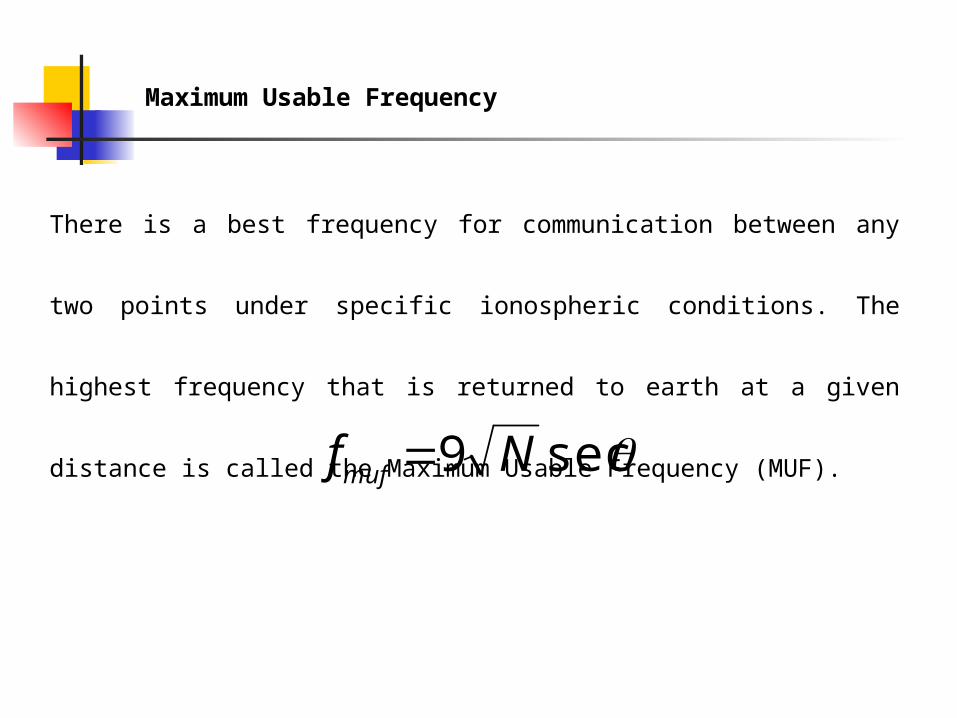
There is a best frequency for communication between any two
points under specific ionospheric conditions. The highest frequency
that is returned to earth at a given distance is called the Maximum
Usable Frequency (MUF).
Maximum Usable Frequency
sec9 Nfmuf

This is the frequency which provides the most consistent
communication and is therefore the best to use. For transmission
using the F2 layer it is defined as
Optimum Working Frequency
sec985.0 Nfowf
This is set by the attenuation in the ionosphere. A practical
value of this is usually taken as 3 MHz.
Lowest Usable Frequency
Satellite Communication
In these systems a communication satellite is placed into
synchronous orbit about 22 000 mi above the earth’s surface. The
transmitter sends a signal using a highly directional antenna to
the satellite. This signal is reamplified within the satellite and
transmitted back to earth. This allows transoceanic links,
frequencies range from 1 GHz to 40 GHz. The received signals
and the retransmitted signals are usually at different carrier
frequencies.

Satellite-Related Terms Earth Stations – antenna systems on or near earth Uplink – transmission from an earth station to a
satellite Downlink – transmission from a satellite to an
earth station Transponder – electronics in the satellite that
convert uplink signals to downlink signals

Ways to CategorizeCommunications Satellites Coverage area
Global, regional, national Service type
Fixed service satellite (FSS) Broadcast service satellite (BSS)
General usage Commercial, military, amateur, experimental

Classification of Satellite Orbits Circular or elliptical orbit
Circular with center at earth’s center Elliptical with one foci at earth’s center
Orbit around earth in different planes Equatorial orbit above earth’s equator Polar orbit passes over both poles Other orbits referred to as inclined orbits
Altitude of satellites Geostationary orbit (GEO) Medium earth orbit (MEO) Low earth orbit (LEO)

Geometry Terms Elevation angle - the angle from the
horizontal to the point on the center of the main beam of the antenna when the antenna is pointed directly at the satellite
Minimum elevation angle Coverage angle - the measure of the portion
of the earth's surface visible to the satellite

Minimum Elevation Angle Reasons affecting minimum elevation angle
of earth station’s antenna (>0o) Buildings, trees, and other terrestrial objects
block the line of sight Atmospheric attenuation is greater at low
elevation angles Electrical noise generated by the earth's heat
near its surface adversely affects reception

GEO Orbit Advantages of the the GEO orbit
No problem with frequency changes Tracking of the satellite is simplified High coverage area
Disadvantages of the GEO orbit Weak signal after traveling over 35,000 km Polar regions are poorly served Signal sending delay is substantial

LEO Satellite Characteristics Circular/slightly elliptical orbit under 2000 km Orbit period ranges from 1.5 to 2 hours Diameter of coverage is about 8000 km Round-trip signal propagation delay less than 20
ms Maximum satellite visible time up to 20 min

LEO Categories Little LEOs
Frequencies below 1 GHz 5MHz of bandwidth Data rates up to 10 kbps Aimed at paging, tracking, and low-rate messaging
Big LEOs Frequencies above 1 GHz Support data rates up to a few megabits per sec Offer same services as little LEOs in addition to voice
and positioning services

MEO Satellite Characteristics Circular orbit at an altitude in the range of 5000 to
12,000 km Orbit period of 6 hours Diameter of coverage is 10,000 to 15,000 km Round trip signal propagation delay less than 50
ms Maximum satellite visible time is a few hours

Frequency Bands Available for Satellite Communications

Satellite Link Performance Factors Distance between earth station antenna and
satellite antenna For downlink, terrestrial distance between earth
station antenna and “aim point” of satellite Displayed as a satellite footprint (Figure 9.6)
Atmospheric attenuation Affected by oxygen, water, angle of elevation, and
higher frequencies
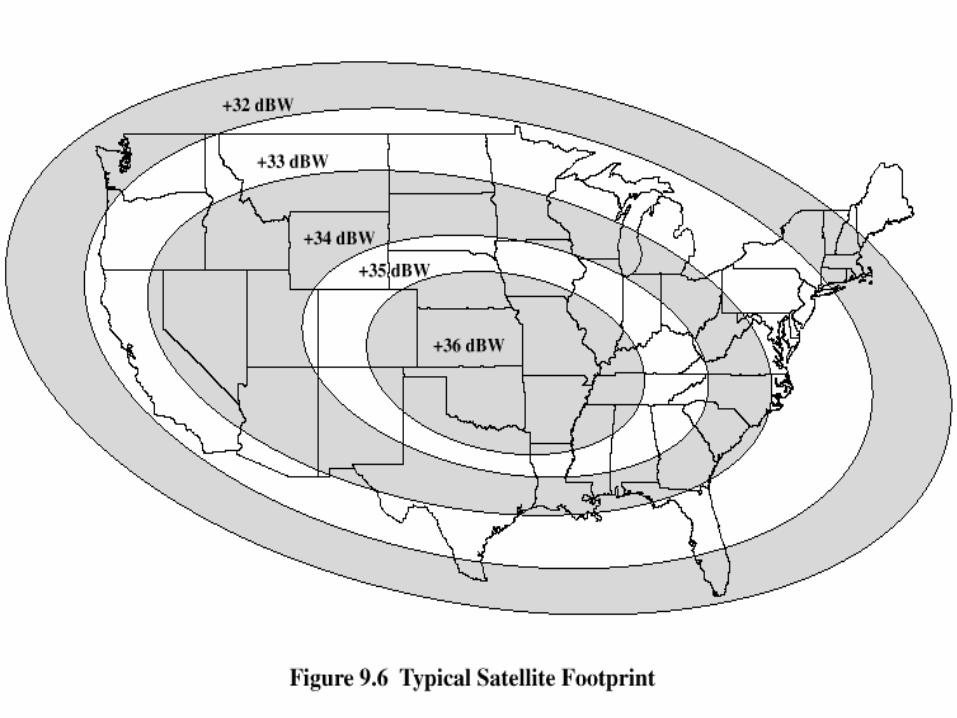
Satellite Footprint

Sat
elli
te N
etw
ork
Con
figu
ratio
ns

The power relation between a transmitted and received power of
any space wave is given as follows
Power Budget for SATCOM
dBfdGGP
PdBrdBt
dBt
r1010 log20log205.32
where Pr is the received power
Pt is the transmitted power
Gt is the gain of the transmitting antenna
Gr is the gain of the receiving antenna
d is the distance (km) between the antennas
f is the frequency in MHz
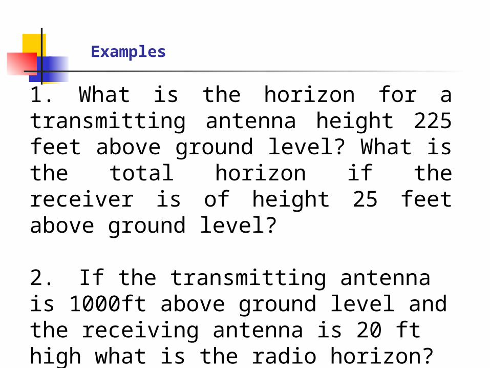
1. What is the horizon for a transmitting antenna height 225 feet above ground level? What is the total horizon if the receiver is of height 25 feet above ground level?
2. If the transmitting antenna is 1000ft above ground level and the receiving antenna is 20 ft high what is the radio horizon?
Examples

3. Determine the distance to the radio horizon for an antenna
40 ft above sea level
4. Calculate the radio horizon for a 500 ft transmitting antenna
and receiving antenna of 20 ft. calculate the required increase in
height for the receiving antenna if a 10% increase in radio horizon
were required.

5. Calculate the power received at a satellite given the following
conditions
Power gain of the transmitting antenna is 30 000
The transmitter drives 2 kW of power into the antenna at a
carrier frequency of 6.21 MHz
The satellite receiving antenna has a power gain of 30
The transmission path is 45 000 km
6. Determine the maximum distance between identical
antennas equally distant above sea level


![VALUE€¦ · Contour Drawing [Project One] Contour Drawing. Contour Line: In drawing, is an outline sketch of an object. [Project One]: Layered Contour Drawing The purpose of contour](https://static.documents.pub/doc/80x56/60363a1e4c7d150c4824002e/value-contour-drawing-project-one-contour-drawing-contour-line-in-drawing-is.jpg)

![THESIS - 東京大学Gravitational waves are ripples of space-time curvature that propagate through the uni- ... [10], space-based Atomic Gravitational wave Interferometric Sensor](https://static.documents.pub/doc/80x56/5f1fcce119219b7304626b1f/thesis-gravitational-waves-are-ripples-of-space-time-curvature-that.jpg)


