Progress In Electromagnetics Research, PIER 47, 1–25, 2004 ELECTROMAGNETIC FIELD SOLUTION IN CONFORMAL STRUCTURES: THEORETICAL AND NUMERICAL ANALYSIS F. Bilotti, A. Al` u, and L. Vegni Department of Applied Electronics University of Roma Tre Via della Vasca Navale n ◦ 84, 00146, Rome, Italy Abstract—A full-wave evaluation of the electromagnetic field in conformal structures with linear loading materials is presented in this paper. The analysis is performed considering at first conformal components with conventional isotropic and homogeneous media in the generalized orthogonal curvilinear reference system. In this first case, a summary of the possible analytical solutions of the vector wave equation obtainable through various factorization techniques is given. Then, the attention is focused on conformal structures involving non-conventional media (anisotropic, chiral, bianisotropic) and in this case the field solution is demanded to a new generalization of the transmission line approach. As an aside, exploiting a contravariant field formulation, which allows writing Maxwell’s equations in the generalized reference system as in the Cartesian one, a useful relationship between the local curvature of the geometry and a suitable inhomogeneity of a related planar structure is presented. Finally, some results, obtained simulating the behavior of patch radiators mounted on curved bodies through the combined application of an extended Method of Line (MoL) numerical algorithm and the theoretical approach here derived, are presented. 1 Introduction 2 Generalized Orthogonal Curvilinear Reference System 3 Field Solution in Conformal Structures with Linear, Isotropic and Homogeneous Materials 4 Complex Media and the Contravariant Approach 5 Isomorphism
Transcript
Progress In Electromagnetics Research, PIER 47, 1–25, 2004
ELECTROMAGNETIC FIELD SOLUTION INCONFORMAL STRUCTURES: THEORETICAL ANDNUMERICAL ANALYSIS
F. Bilotti, A. Alu, and L. Vegni
Department of Applied ElectronicsUniversity of Roma TreVia della Vasca Navale n84, 00146, Rome, Italy
Abstract—A full-wave evaluation of the electromagnetic field inconformal structures with linear loading materials is presented inthis paper. The analysis is performed considering at first conformalcomponents with conventional isotropic and homogeneous media inthe generalized orthogonal curvilinear reference system. In this firstcase, a summary of the possible analytical solutions of the vectorwave equation obtainable through various factorization techniques isgiven. Then, the attention is focused on conformal structures involvingnon-conventional media (anisotropic, chiral, bianisotropic) and in thiscase the field solution is demanded to a new generalization of thetransmission line approach. As an aside, exploiting a contravariantfield formulation, which allows writing Maxwell’s equations in thegeneralized reference system as in the Cartesian one, a usefulrelationship between the local curvature of the geometry and a suitableinhomogeneity of a related planar structure is presented. Finally,some results, obtained simulating the behavior of patch radiatorsmounted on curved bodies through the combined application ofan extended Method of Line (MoL) numerical algorithm and thetheoretical approach here derived, are presented.
1 Introduction
2 Generalized Orthogonal Curvilinear Reference System
3 Field Solution in Conformal Structures with Linear,Isotropic and Homogeneous Materials
4 Complex Media and the Contravariant Approach
5 Isomorphism
2 Bilotti, Alu, and Vegni
6 Numerical Results
7 Conclusions
References
1. INTRODUCTION
The popularity and the demand for conformal components inmicrowave applications has been growing in the last decades, in parallelwith the interest in employing electromagnetic devices in spacecraft,satellites, aircraft and land vehicles, for which compactness and dragreduction are very important issues [1–13]. For this reason, extensiveresearch efforts have been recently devoted to develop accurate andefficient analysis tools and design procedures for integrated circuitsand radiative components mounted on curved surfaces, avoidingexpensive and approximate experimental attempts. In the case ofsimple geometries (e.g., planar, cylindrical, spherical, etc.) and linear,isotropic and homogeneous dielectric materials, the full-wave theoryis well established and analytical solutions are already available (see[14] and references therein). Therefore, nowadays the research in thesecases is mainly devoted to find out new and fast design techniques.
When non-canonical surfaces are involved, instead, the analysisgrows in complexity, due to the local curvature of the structure, andspending efforts on design procedures becomes a step ahead. Thefirst aim in this case consists in the development of an accurateand efficient analysis tool, which may simulate the electromagneticbehavior of the conformal component varying the electrical andgeometrical parameters to match the given requirements. For thispurpose, a proper theoretical investigation is needed.
The main difficulty encountered when approaching the electro-magnetic problem in curved structures is the analytical complexity ofthe involved equations, which very often cannot be solved in closedforms. These difficulties grow even more in presence of complex me-dia, such as materials exhibiting the magneto-electric effect (chiral, bi-anisotropic, etc.), whose behavior in radiating and circuit componentshas been investigated in the past years [15–23] and has shown verypromising features. The actual difficulties in this theoretical researchfield, thus, mainly depend on the complexity of the required mathe-matical background and on the fact that a well established and generaltheory on conformal structures has not been already carried out andpublished in the open technical literature. This paper is an attempt topresent in a unified theory some new theoretical developments in thesolution of the electromagnetic field in conformal structures. In the
EM field solution in conformal structures 3
last part of the paper, then, the theory here presented is applied to an-alyze numerically some conformal components following an extendedMoL numerical procedure as proposed by the authors in a recent work[24].
The structure of the present work is given in the following. InSection 2 a brief description of the generalized orthogonal curvilinearreference system and a detailed justification for its employment inthe present analysis will be discussed. In Section 3 the solution ofthe electromagnetic field in presence of linear, isotropic, homogeneousmedia will be summarized and discussed, showing in which referencesystems it is possible to find a closed-form analytical solution and inwhich others a numerical solution is unavoidable. In Section 4 thepresence of complex materials will be addressed and a new set oftransmission line equations in the generalized orthogonal curvilinearreference system will be derived, showing their utility in the analysisof conformal structures both for analytical and numerical tools. InSection 5, a useful relationship between the local curvature of thegeometry and a suitable inhomogeneity introduced in an isomorphicplanar structure is presented, which can be employed to simplify theanalysis of electromagnetic components mounted on curved surfaces.Finally, in Section 6, some numerical results, obtained exploitingthe generalized MoL algorithm described in [24] and based on theisomorphism proposed in Section 5, are presented.
2. GENERALIZED ORTHOGONAL CURVILINEARREFERENCE SYSTEM
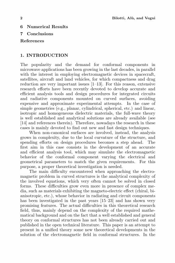
In the following we will refer to an integrated conformal structuremounted on a curved surface, such as the one depicted in Fig. 1.The related electromagnetic problem consists in a differential system(Maxwell’s equations) with prescribed boundary conditions on theinterfaces between the conformal slabs that compose the structure,on the conformal metallic surfaces and at infinity (the radiationcondition).
This problem can be solved either analytically or numerically, butin both cases a suitable modeling of the curved surfaces is needed.Very often they are roughly represented by canonical surfaces, such asportions of spherical or cylindrical surfaces, but this approximationdoes not always yield correct results in the simulation process.The accuracy of the solution, in fact, obviously depends on theapproximation of the real curvature of the structure. When this kindof solution is viable, however, the electromagnetic analysis is usuallydeveloped in the related reference system (i.e., cylindrical and spherical
4 Bilotti, Alu, and Vegni
metallic curved surface
conformal dielectric slab
conformal metallic trace
Figure 1. An example of an integrated conformal structure.
for structures approximated by cylinders or spheres, respectively),where the curved interfaces coincide with coordinate surfaces and thefield components are tangential or orthogonal to the surface at eachpoint. A direct consequence, in fact, is that the imposition of Dirichletor Neumann boundary conditions becomes straightforward since theydo automatically factorize and refer only to one single field component.
On the other hand, when canonical geometries are not suitableto describe the interface surfaces, a more extensive theory is neededand the generalized orthogonal reference system may be successfullyemployed for this purpose. A conformal interface, in fact, can bevery often expressed or approximated (generally in a more accurateway than in the case of the aforementioned canonical geometries) as acoordinate surface in an orthogonal reference system.
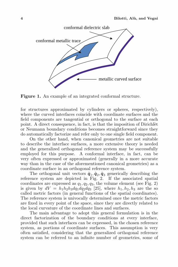
The orthogonal unit vectors q1, q2, q3 generically describing thereference system are depicted in Fig. 2. If the associated spatialcoordinates are expressed as q1, q2, q3, the volume element (see Fig. 2)is given by dV = h1h2h3dq1dq2dq3 [25], where h1, h2, h3 are the socalled metric factors (in general functions of the spatial coordinates).The reference system is univocally determined once the metric factorsare fixed in every point of the space, since they are directly related tothe local curvature of the coordinate lines and surfaces.
The main advantage to adopt this general formulation is in thedirect factorization of the boundary conditions at every interface,provided that such interfaces can be expressed, in the chosen referencesystem, as portions of coordinate surfaces. This assumption is veryoften satisfied, considering that the generalized orthogonal referencesystem can be referred to an infinite number of geometries, some of
EM field solution in conformal structures 5
Figure 2. Unit vectors and volume element in the generalizedorthogonal curvilinear reference system.
which are reported in Table 1.The number of orthogonal systems for which this formulation can
be applied is not limited to those reported in the table, but suitablereference systems may be synthesized, depending on necessity, through
Table 1. Some orthogonal reference systems, with related coordinatevariables and metric factors.
Reference System Spatial Variables Metric Factors
q1 q2 q3 h1 h2 h3
Cartesian x y z 1 1 1
Circular Cylindrical ρ φ z 1 ρ 1
Parabolic Cylindrical u v z√u2 + v2
√u2 + v2 1
Elliptic Cylindrical u v z a√
sin2 v + sinh2 u a√
sin2 v + sinh2 u 1
Spherical r θ φ 1 r r sin θ
Prolate Spheroidal ξ η φ a√
sin2 η + sinh2 ξ a√
sin2 η + sinh2 ξ a sinη + sinh ξ
Oblate Spheroidal ξ η φ a√
sin2 ξ + sinh2 η a√
sin2 ξ + sinh2 η a cosξ + cosh η
Parabolic u v φ√u2 + v2
√u2 + v2 uv
Conic µ v 1
√µ2−v2| |√
µ2−a2√
b2−µ2
√µ2−v2| |√
µ2−a2√
v2−b2
Paraboloidal µ v
√µ−λ)( v−λ)
2√
a2−λ√
b2−λ
√( −µ)(v−µ)
2√
a2−µ√
b2−µ
√( −v)(µ−v)
2√
a2−v√
b2−v
Ellipsoidal µ v
√µ−λ)( v−
2√
a2−λ√
b2−λ√
c2−λ
√( −µ)(v−µ)
2√
a2−µ√
b2−µ√
c2−µ
√(λ −v)(µ−v)
2√
a2−v√
b2−v√
c2−v
Bipolar u v z acosh v−cos u
acosh v−cos u
1
Bispherical u v φ acosh v−cos u
acosh v−cos u
a sin ucosh v−cos u
Cardioid Cylinder u v φ acosh u−cos v
acosh u−cos v
a sin ucosh u−cos v
Cardioid Cylinder µ v z (µ2 + v2)−3/2 (µ2 + v2)−3/2 1
Tangent Sphere µ v ψ 1µ2+v2
1µ2+v2
µµ2+v2
λ
λ
λ
λ λ
λ λ
λ) λ
6 Bilotti, Alu, and Vegni
the use of conformal transformations in the complex plane, as shownin [26].
Spatial variables and scale factors associated to each referencesystem are also reported in the table. It has to be observed that somereference systems require a further assignment of some geometricalparameters.
3. FIELD SOLUTION IN CONFORMAL STRUCTURESWITH LINEAR, ISOTROPIC AND HOMOGENEOUSMATERIALS
In this section we briefly show a possible analytical solution of theelectromagnetic field in conformal geometries when linear, isotropicand homogenous materials are considered. Assuming a time harmonicdependence ejωt and considering a source free region, the vector waveequations for the electric (E) and magnetic (H) fields are of theHelmholtz kind:
∇2E − k2E = 0
∇2H − k2H = 0(1)
where k2 = ω2µε, being ω the angular frequency and µ, ε thepermittivity and permeability of the medium, respectively.
The main goal is to solve analytically these vector equations, inorder to express in a closed form the electromagnetic field excited inthe conformal structure. To this end, the first problem to be consideredis the reduction of the vector Helmholtz equation to scalar uncoupleddifferential equations. Then, these scalar equations should be solved,preferably in a closed form.
The problem is usually approached by directly projecting eachvector equation on the three coordinate directions. Consideringthe generalized reference system, three coupled scalar differentialequations are obtained and there is no way to reduce the system toscalar equations containing only one unknown each. Specifying theproblem to a given reference system, on the other hand, it can beshown that uncoupled equations can be obtained in some cases: inCartesian coordinates, as well known, the three scalar equations are alldecoupled whereas in circular cylindrical, parabolic cylindrical, ellipticcylindrical, and bipolar systems only the scalar equation along theaxial direction is decoupled. Provided that we can find an analyticalsolution for this equation, however, it can be shown that the wholespatial electromagnetic field can be related to this solution, and, thus,expressed analytically as well. In the spherical reference system, whichdoes not belong to the previous class, it is also possible to reduce the
EM field solution in conformal structures 7
vector equation to a scalar one by using in addition the divergenceequations.
In order to extend the family of orthogonal reference systemswhere this reduction is possible, we can operate introducing theBorgnis’ potential functions U and V [27]. In those reference systemswhere the following two conditions hold:
h3 = 1 and∂
∂q3
(h1
h2
)= 0 (2)
it can be proved that the overall electromagnetic field can be expressedas follows [27]:
Eq1(q1, q2, q3) =1h1
∂2U(q1, q2, q3)∂q3∂q1
− jωµ1h2
∂V (q1, q2, q3)∂q2
Eq2(q1, q2, q3) =1h2
∂2U(q1, q2, q3)∂q2∂q3
+ jωµ1h1
∂V (q1, q2, q3)∂q1
Eq3(q1, q2, q3) =∂2U(q1, q2, q3)
∂q23
+ k2U(q1, q2, q3)
(3)
Hq1(q1, q2, q3) =1h1
∂2V (q1, q2, q3)∂q3∂q1
+ jωε1h2
∂U(q1, q2, q3)∂q2
Hq2(q1, q2, q3) =1h2
∂2V (q1, q2, q3)∂q2∂q3
− jωε1h1
∂U(q1, q2, q3)∂q1
Hq3(q1, q2, q3) =∂2V (q1, q2, q3)
∂q23
+ k2V (q1, q2, q3)
(4)
while the Borgnis’ potentials satisfy these two equations of the samekind:
∇2tU(q1, q2, q3) +
∂2U(q1, q2, q3)∂q2
3
+ k2U(q1, q2, q3) = 0 (5)
∇2tV (q1, q2, q3) +
∂2V (q1, q2, q3)∂q2
3
+ k2V (q1, q2, q3) = 0 (6)
being
∇2t =
1h1h2
[∂
∂q1
(h2
h3
∂
∂q1
)+
∂
∂q2
(h1
h2
∂
∂q2
)].
Referring to Table 1, the reference systems satisfying (2), and forwhich, thus, scalar equations like (5), (6) can be derived, are thefollowing seven: Cartesian, circular cylindrical, parabolic cylindrical,elliptic cylindrical, spherical, bipolar, and conical. We can observe
8 Bilotti, Alu, and Vegni
that, apart from the conical case, equations (5), (6) are scalarHelmholtz equations in all these reference systems.
Once scalar uncoupled differential equations are obtained, thesecond problem to be considered is to find analytical solutions ofthese equations. A simple way to explore the possibility of aclosed form solution for a partial differential equation is to checkwhether or not variable factorization can be applied to the scalarequations. A factorized analytical solution of the scalar Helmholtzequation can be directly found in eleven reference systems (Cartesian,circular cylindrical, parabolic cylindrical, elliptic cylindrical, spherical,prolate spheroidal, oblate spheroidal, parabolic, conical, paraboloidal,ellipsoidal) and it is expressed in terms of particular sets of orthogonalfunctions [26]. On the other hand, Borgnis’ potential theory allowsreducing the vector wave equation to a scalar differential one of theHelmholtz kind in six reference systems (Cartesian, circular cylindrical,parabolic cylindrical, elliptic cylindrical, spherical, bipolar), whileequations (5) and (6) with factored analytical solutions can be foundin the conical system. Eventually, we can conclude that among theorthogonal systems of Table 1, the following admit a scalar equationand a closed form solution: Cartesian, circular cylindrical, paraboliccylindrical, elliptic cylindrical, spherical and conical.
In the other reference systems, the solution of the electromagneticfield should be obtained numerically. For a convenient reference, theprevious discussion is summarized in Table 2.
4. COMPLEX MEDIA AND THE CONTRAVARIANTAPPROACH
In this section we present a different approach to solve theelectromagnetic problem in conformal structures. Such an approach,based on an extension of the transmission line formulation, iseffective also when “complex media” are involved. Here and in thefollowing the expression “complex media” refers to materials whoseconstitutive relations involve anisotropic behaviors and/or magneto-electric coupling. As shown in the previous section, the analyticalsolution, even in the case of isotropic homogeneous media, is limitedto some reference systems only and it is not possible in the generalcase. When considering complex media as substrates for integratedconformal structures, vector wave equations for E and H fields are nolonger of the Helmholtz kind and the solution becomes more difficulteven in the simplest reference systems. Limiting our study to linear
EM field solution in conformal structures 9
Table 2. Analytical solution possibility of the vector wave equationin linear, isotropic and homogeneous media for the reference systemsreported in Table 1.
Reference System 1st Problem: Scalar Equation
2nd Problem: Analytical Solution
Final Result
Direct
Projection Borgnis Potentials
Solution by Factorization
Analytical (A) Numerical (N)
Cartesian YES YES YES A Circular Cylindrical YES YES YES A Parabolic Cylindrical YES YES YES A Elliptic Cylindrical YES YES YES A Spherical NO YES YES A Prolate Spheroidal NO NO YES N Oblate Spheroidal NO NO YES N Parabolic NO NO YES N Conic NO YES YES A Paraboloidal NO NO YES N Ellipsoidal NO YES N Bipolar YES YES NO N Bispherical NO NO NO N Toroidal NO NO NO N Cardioid Cylinder NO NO NO N Tangent Sphere NO YES NO N
NO
materials, the constitutive relations can be written as:B = µ(q1, q2, q3) · H + β(q1, q2, q3) · ED = α(q1, q2, q3) · H + ε(q1, q2, q3) · E
(7)
where the previous time-harmonic variation law has been assumed.ε and µ are the permittivity and permeability tensors, respectively,while α and β take into account the coupling effect between electricand magnetic fields (magneto-electric effect). They collapse to scalarquantities when anisotropic effects are not present. Moreover, theirelements satisfy some physical constraints, as widely discussed in [28].
Since in general the curl expression is quite awkward in referencesystems different from the canonical ones, curl Maxwell’s equations
∇× E = −jω(µ · H + β · E)
∇× H = jω(α · H + ε · E)(8)
should be properly manipulated in order to get a more convenientformulation. Adopting the following change of variables and
10 Bilotti, Alu, and Vegni
normalizations, in fact:E = K · EH = K · H
, ∇r =1
jk0∇,
εr = ε−1
0 ε
µr
= µ−10 µ
,
αr = c0α
βr
= c0β
where k0 = ω√ε0µ0, c0 = 1/
√ε0µ0, and
K =
h1 0 00 h2 00 0 h3
∇ =
0 −∂/∂q3 ∂/∂q2
∂/∂q3 0 −∂/∂q1
−∂/∂q2 ∂/∂q1 0
curl Maxwell’s equations can be rewritten in the following form:
(∇r + β
r
)· E = −µ
r· Z0H
(∇r − αr) · Z0H = εr · E(9)
where Z0 =√
µ0/ε0 and v = h1h2h3K−1 · v · K−1, being v =
εr,µr,αr,βr.It is worth to underline that, since the obtained equations in
the contravariant fields E and H [29] are formally equivalent to thevector equations obtainable in the Cartesian geometry, the formalismhere derived allows handling Maxwell equations in every orthogonalreference system in the same way as in the Cartesian case. Thisproperty leads to important simplifications and may be employed,as will be shown in the next section, even in a more extensive wayto find out analytical solutions of the electromagnetic field sustainedby conformal structures. Basically, the relation between (9) and(8) is straightforward: the complexity related to the locally varyingcurvature in the geometry (in (8)) has been suitably transferred in avariation of the medium inhomogeneity with the spatial coordinates(in (9)), following the transformation v = h1h2h3K
−1 · v · K−1.Exploiting the formalism introduced by (9), the derivation of a
generalized transmission line system of equations relating the fieldcomponents becomes a straightforward task, as in the Cartesian case[30]. Starting from (9), eliminating the longitudinal components ofthe fields (with respect to q3 direction), the following telegraphers’equations for the transverse fields Et and Ht can be derived:
∂Et
∂q3
= A · Et + Z · Ht
∂Ht
∂q3
= Y · Et + B · Ht
(10)
EM field solution in conformal structures 11
where qi = jk0qi (i = 1, 2, 3).The matrices A,Z,Y ,B are operatorial matrices, applied to the
transverse field components. Their elements have, in the general case,a complicated form and depend on the constitutive parameters, onthe scale factors and on the derivatives with respect to the transversevariables. The elements of A and Z are reported in the following, whilethose ones of the two other matrices Y and B can be easily derivedby using the duality principle:
A11 = −β21 −(
∂
∂q1
− β23
) (α33
∆
(∂
∂q2
− β31
)+
µ33
∆ε31
)
−µ23
(ε33
∆
(∂
∂q2
− β31
)+
β33
∆ε31
)
A12 = −β22 +(
∂
∂q1
− β23
) (α33
∆
(∂
∂q1
+ β32
)− µ33
∆ε32
)
+µ23
(ε33
∆
(∂
∂q1
+ β32
)− β33
∆ε32
)
A21 = β11 −(
∂
∂q2
+ β13
) (α33
∆
(∂
∂q2
− β31
)+
µ33
∆ε31
)
+µ13
(ε33
∆
(∂
∂q2
− β31
)+
β33
∆ε31
)
A22 = β12 +(
∂
∂q2
+ β13
) (α33
∆
(∂
∂q1
+ β32
)− µ33
∆ε32
)
−µ13
(ε33
∆
(∂
∂q1
+ β32
)− β33
∆ε32
)
12 Bilotti, Alu, and Vegni
Z11 = −µ21 −(
∂
∂q1
− β23
) (µ33
∆
(∂
∂q2
+ α31
)− α33
∆µ31
)
−µ23
(β33
∆
(∂
∂q2
+ α31
)− ε33
∆µ31
)
Z12 = −µ22 +(
∂
∂q1
− β23
) (µ33
∆
(∂
∂q1
− α32
)+
α33
∆µ32
)
+µ23
(β33
∆
(∂
∂q1
− α32
)+
ε33
∆µ32
)
Z21 = µ11 −(
∂
∂q2
+ β13
) (µ33
∆
(∂
∂q2
+ α31
)− α33
∆µ31
)
+µ13
(β33
∆
(∂
∂q2
+ α31
)− ε33
∆µ31
)
Z22 = µ12 +(
∂
∂q2
+ β13
) (µ33
∆
(∂
∂q1
− α32
)+
α33
∆µ32
)
−µ13
(β33
∆
(∂
∂q1
− α32
)+
ε33
∆µ32
)
being ∆ = µ33ε33 − α33β33 and vij the elements of tensor v.The system here found is still analytical and does not contain
any numerical approximation. Its exact solution is very difficult in thegeneral case, and solutions are not known except for very special cases.However, the structure of these equations is very suitable for numericalapplications and in particular for a MoL procedure [31–36]. In thiscase, as extensively discussed in [24], the four operatorial matricesin (10) can be made algebraic after a proper 2-D discretization onthe transverse coordinate surface q3=constant and a total-derivativesystem can be easily obtained, analytically solvable along the thirddirection (q3). This procedure, described more thoroughly in [24],extends the MoL algorithm [31–36] to conformal components involvingcomplex media and represents an easy and efficient way to studynumerically these structures.
Moreover, (10) are commonly used in electromagnetic theory asa starting point to derive the spectral dyadic Green’s function ofintegrated structures with a prescribed coordinate stratification axis(in this case q3). Applying a suitable 2D spectral transform, thetransverse derivatives appearing in A,Z,Y and B become algebraic aswell and it is possible to look for analytical solutions of the equations inthe remaining spatial variable q3. For canonical reference systems theproper spectral transform is already known (e.g., Fourier transform,
EM field solution in conformal structures 13
Hankel transform, Legendre transform) and the transverse derivativesare replaced by proper combinations of transverse wave-numbers, asit can be readily recognized for isotropic materials. In this case, theGreen’s function derivation from (10) is straightforward, while for otherreference systems the preliminary step of finding a proper spectraltransform has to be performed and is out of the scopes of the presentpaper.
5. ISOMORPHISM
As already pointed out in the previous section, the formalism presentedabove rewrites Maxwell’s equations in the generalized reference systemin the same form as in the Cartesian case. In the following, we willshow that this implies the possibility of associating a suitable planarstructure to the conformal one under analysis or, in other words, tofind out an isomorphism between the sets of conformal and planarcomponents.
Let’s consider a stratified conformal component as the onedepicted in Fig. 3a. The interfaces between two adjacent conformalslabs are assumed to be properly represented in a given referencesystem (in this case the cylindrical one) as coordinate surfacesqi=constant. In addition, each i-th slab is characterized by theconstitutive tensors εi, µ
i, αi, β
i, in general depending on the spatial
coordinates. Let us assume that E and Hare the electromagneticfield solutions of Maxwell’s equations in every conformal slab andthat the proper boundary conditions are satisfied. As stated before,an isomorphic planar structure (Fig. 3b) can be synthesized in theCartesian reference system (x, y, z), whose interface surfaces areobtained through the simple transformations:
q1 = constant1 → x = constant1q2 = constant2 → y = constant2q3 = constant3 → z = constant3
and whose planar slabs are filled up by materials with transformedconstitutive tensors expressed in the form:
v(x, y, z) = h1(x, y, z)h2(x, y, z)h3(x, y, z)K−1(x, y, z) · v(x, y, z)·K−1(x, y, z)
14 Bilotti, Alu, and Vegni
ε0, µ0
q3 = ρ = c
ε2,µ2,α2,β2
q2 = ϕ = γ q2 = ϕ = δ
ε0, µ0
ε2, µ2, α2, β2
ε1,µ1,α1,β1
w
L
y = γ + 2π y = δ + 2π
z = c
y = γ y = δ
q3 = ρ = b
q3 = ρ = a
ε1, µ1, α1, β1
w
L
L
w
ε0, µ0
z = b
z = a
(a)
(b)
Figure 3. (a) Conformal metallic patch mounted on a cylindricalsupport and (b) its isomorphic geometry. The associated referencesystems are: q1 = z, q2 = ϕ, q3 = ρ; h1 = h3 = 1, h2 = ρ for Fig.3a and q1 = ˆx, q2 = ˆy, q3 = ˆz for Fig. 3b.
=
h2h3
h1v11 h3v12 h2v13
h3v21h1h3
h2v22 h1v23
h2v31 h1v32h1h2
h3v33
(11)
Following (9), the electromagnetic field E, H excited in this isomorphicplanar structure is contravariant with respect to the one excited in theconformal structure, i.e.,
E = K(x, y, z) · EH = K(x, y, z) · H
(12)
and therefore solving one of the two electromagnetic problems implies
EM field solution in conformal structures 15
solution of the second one. The equivalence of the two differentialproblems satisfied respectively by E,H and E, H is granted, following[28], by:
• the same system of equations: Maxwell’s equations are invariantwith respect to the transformation here introduced, as shown inthe previous section;
• the same set of boundary conditions on the interfaces separatingthe stratified slabs: on coordinate surfaces the boundaryconditions are factorized and refer to the tangential componentsof the field;
• the same radiation condition at infinity.In the case of closed structures, the equivalence is straightforward andcan be easily employed to model conformal waveguides. In the generalcase, however, particular attention should be paid to:
• special values of the spatial variables for which the coordinatesurfaces are singular (i.e., they reduce to lines or points, as ithappens for instance for the coordinate surface ρ = 0 in thecircular cylindrical system of Fig. 3): in this case, the isomorphicplanar equivalent remains a plane, but on this surface someconstitutive elements go to infinity, as visible from (11). Thesesingularities in the constitutive tensors, though not physical,ensure the right behavior of the field on the planes isomorphicto the singular surfaces, as discussed later.
• open structures: the empty space (i.e., air surrounding theconformal component) is transformed into an inhomogeneousmedium, whose constitutive tensors are:
ε0 =
h2h3
h1ε0 0 0
0h1h3
h2ε0 0
0 0h1h2
h3ε0
µ0
=
h2h3
h1µ0 0 0
0h1h3
h2µ0 0
0 0h1h2
h3µ0
.
• geometries with periodic coordinates: the planar equivalentstructure will follow the same periodicity and, since also the
16 Bilotti, Alu, and Vegni
excitation will have a periodic nature, the whole electromagneticfield maintains for symmetry the same periodicity and may bestudied only in one spatial period.
As an example involving also the particular cases now cited, Fig. 3arepresents a conformal cylindrical patch with a homogeneous substrateand a superstrate. Its planar equivalent is shown in Fig. 3b, whichdepicts an infinite array of rectangular patches, periodical along y,loaded by inhomogeneous media. The equations satisfied by the fieldE,H in the cylindrical structure are the same satisfied in the planarstructure by E, H and the two fields are linked by relation (12). Atthe interfaces the boundary conditions are of the same form and arerelated to the same field components in the two isomorphic referencesystems. Also the radiation condition is expressed in an equivalentform: the fields decay for q3 = ρ → +∞, z → +∞ in both thestructures. Referring to singular surfaces, when q3 = ρ → 0+, thecoordinate surface becomes a line. In the equivalent planar structureon the plane z → 0+ the constitutive tensors become singular:
v0 → 0 0 0
0 ∞ 00 0 0
,
where
v0 = v0
ρ 0 0
0 1/ρ 00 0 ρ
with v0 = ε0, µ0, v0 = ε0, µ0.
Notice that, though not physical, such an expression for theconstitutive tensors avoids radiation of power towards the region z < 0,whose points are not mapped in the cylindrical structure (for whichq3 = ρ ≥ 0). Examples like the previous one, or even more complex,can be analyzed in more detail, showing the complete correspondenceof the two field solutions.
As already pointed out, it is worth mentioning that the proposedisomorphism essentially transfers the complexity related to the localcurvature of the conformal geometry into a proper inhomogeneityof the media characterizing the equivalent planar component. As aconsequence of this property, the analysis of a conformal componentcan be equivalently performed by studying its isomorphic planarstructure and then obtaining the electromagnetic field of interestthrough (12). It has to be noted, however, that the planar analysismaintains the same mathematical difficulties if one is interested ina rigorous analytical solution of the field equations (which is obvious
EM field solution in conformal structures 17
since the resulting equations in the two reference systems are the same).Nevertheless, the introduction of the isomorphic planar structuremakes the numerical analysis of conformal components viable throughFinite Difference Time Domain (FDTD), Finite Element (FE), MoLand other well established numerical methods that can take intoaccount possible medium inhomogeneities in planar structures. In thisdirection, the numerical results presented in [24], based on a properextension of the MoL to study conformal components, may be revisedas a straightforward application of the theoretical approach developedin this paper. Some details about this concept will be addressed in thefollowing section.
As a final remark concerning the isomorphism here presented, it isworth to notice that the complete mathematical equivalence betweenthe conformal problem and the related planar one retains also therelated physical phenomena. For instance, creepy waves or mutualcoupling are still present in the equivalent planar mapping and theircontribution to the radiation process may still be considered andweighted. This is due to the fact that the dispersion relation associatedto the transformed inhomogeneous planar structure remains unchangedand the solutions corresponding to the curved structure are indeed fullypreserved.
6. NUMERICAL RESULTS
As previously remarked, the generalized transmission line formulationderived in section IV can be applied to develop a full-wave numericaltool based on the MoL to simulate the behavior of conformal structures.As shown by the authors in [24], the application of the MoLwhen complex media and conformal structures are involved is not astraightforward matter and a proper extension of the method is needed.
The details of the extended method may be found in [24] wheresome numerical results, showing the capabilities of the numerical tooldeveloped following the MoL approach, are also presented. Thosenumerical results already validate the theoretical formulation presentedin this paper. In addition, in this section we propose a revised readingof some of them, based on the application of the approach presentedin Section 5.
The first example we consider here is related to the simple teststructure reported in Fig. 4a. Such a structure has been alreadyanalyzed through the extended MoL approach in the cylindricalreference system [24] and the numerical results there obtained agreevery well with the ones reported in the literature [37]. In this casewe have performed a new simulation of the wraparound cylindrical
18 Bilotti, Alu, and Vegni
Figure 4. (a) Wrap-around cylindrical patch antenna. Thegeometrical and electrical parameters are: L = 80 mm, h = 1.6 mm,a = 20 mm, zp = upper patch edge position, ϕp = 0, εr = 4.2 + j0.02.(b) Isomorphic planar structure.
EM field solution in conformal structures 19
0,7 0,8 0,9 1,0 1,1 1,2-40
-20
0
20
40
60
80
Real part (Cavity model) Imaginary part (Cavity model) Real part (MoL) Imaginary part (MoL)
Inpu
t Im
peda
nce
Zin
Frequency [GHz]a)
0¡ 30¡ 60¡ 90¡ 120¡ 150¡ 180¡0,0
0,2
0,4
0,6
0,8
1,0
Nor
mal
ized
Ele
ctric
Fie
ld A
mpl
itude
Elevation Angle T [¡]
I = 0f = 900 [MHz]
b)
[Ω]
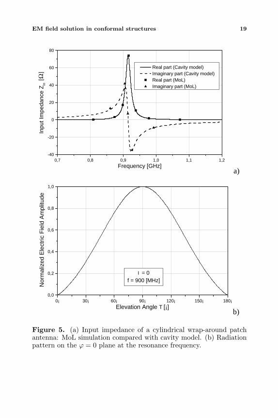
Figure 5. (a) Input impedance of a cylindrical wrap-around patchantenna: MoL simulation compared with cavity model. (b) Radiationpattern on the ϕ = 0 plane at the resonance frequency.
20 Bilotti, Alu, and Vegni
L
a
a+h
r tan
L/(a+h)
δε
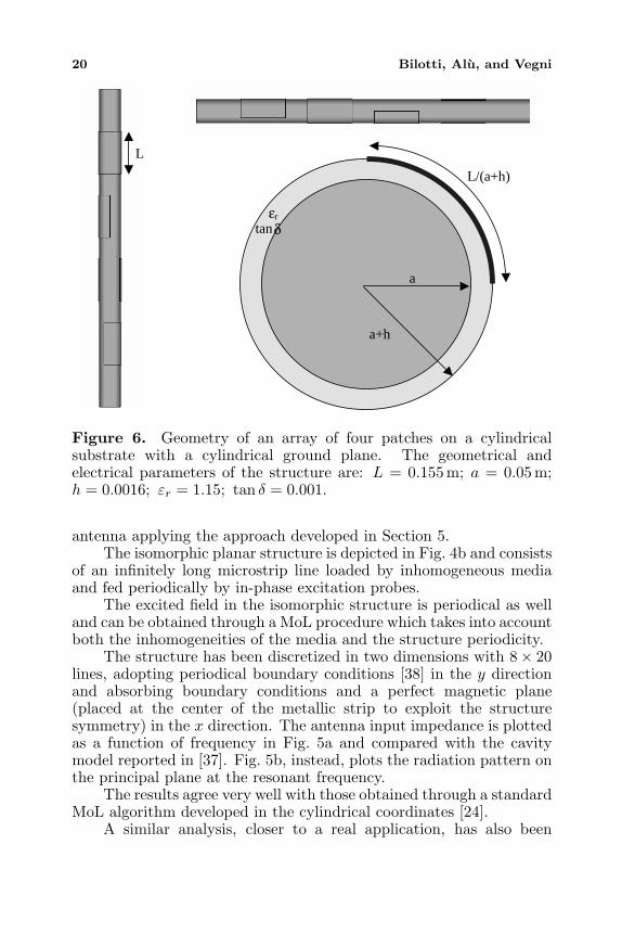
Figure 6. Geometry of an array of four patches on a cylindricalsubstrate with a cylindrical ground plane. The geometrical andelectrical parameters of the structure are: L = 0.155 m; a = 0.05 m;h = 0.0016; εr = 1.15; tan δ = 0.001.
antenna applying the approach developed in Section 5.The isomorphic planar structure is depicted in Fig. 4b and consists
of an infinitely long microstrip line loaded by inhomogeneous mediaand fed periodically by in-phase excitation probes.
The excited field in the isomorphic structure is periodical as welland can be obtained through a MoL procedure which takes into accountboth the inhomogeneities of the media and the structure periodicity.
The structure has been discretized in two dimensions with 8× 20lines, adopting periodical boundary conditions [38] in the y directionand absorbing boundary conditions and a perfect magnetic plane(placed at the center of the metallic strip to exploit the structuresymmetry) in the x direction. The antenna input impedance is plottedas a function of frequency in Fig. 5a and compared with the cavitymodel reported in [37]. Fig. 5b, instead, plots the radiation pattern onthe principal plane at the resonant frequency.
The results agree very well with those obtained through a standardMoL algorithm developed in the cylindrical coordinates [24].
A similar analysis, closer to a real application, has also been
EM field solution in conformal structures 21
-25dB
-20dB
-15dB
-10dB
-5dB
0dB0¡
30¡
60¡
90¡
120¡
150¡
180¡
210¡
240¡
270¡
300¡
330¡
-25dB
-20dB
-15dB
-10dB
-5dB
0dB
-25dB
-20dB
-15dB
-10dB
-5dB
0dB0¡
30¡
60¡
90¡
120¡
150¡
180¡
210¡
240¡
270¡
300¡
330¡
-25dB
-20dB
-15dB
-10dB
-5dB
0dB
(a) (b)
Figure 7. Radiation patterns of the array of Fig. 6, (a) horizontalplane, (b) vertical plane.
performed considering the more complicated cylindrical structuredepicted in Fig. 6. In this case the antenna consists of four metallicpatches located on a cylindrical substrate and the structure hasbeen tested again exploiting the isomorphic planar structure obtainedapplying the transformation rules presented in Section 5.
The patches have been designed to resonate at 900 MHz and towork with a double linear polarization. Their position should grantan omni-directional radiation pattern for a whole array, for a typicalradiobase station for mobile communications.
In Fig. 7, the radiation patterns on the horizontal (Fig. 7a) andvertical (Fig. 7b) planes are depicted, as obtained from our simulation.The directivity is around 3.8 dB.
7. CONCLUSIONS
This paper has the aim to present an extensive formulation forthe treatment of Maxwell’s equations in the generalized orthogonalreference system. The theoretical approach starts with an overviewof the possible analytical solutions of the field wave equations in thecase of isotropic and homogeneous media, showing the limited numberof reference systems in which a complete solution is viable. Then, ageneral formulation valid for any orthogonal reference system and anylinear material has been presented, showing its advantage of handlingMaxwell’s equations formally as in the Cartesian reference system. Afirst result is the generalization of the transmission line equations,
22 Bilotti, Alu, and Vegni
relating the transverse components of the electromagnetic field withrespect to a generic coordinate reference direction. This system ofequations is suitably written both for the application of a numericalMoL procedure, which have been already developed by the authors[24], and for an analytical approach in the spectral domain.
Moreover, by exploiting the same mathematical formalism aninteresting relation between conformal components and equivalentplanar structures has been presented. This result essentially transfersthe complexities related to the varying local curvature of thecomponent into a suitable variation of the medium inhomogeneitiesand may be successfully employed to simplify the numerical analysisof closed and open microwave conformal components. Some numericalexamples, based on the application of the MoL, have been finallypresented to show the potential impact of the proposed isomorphismin the simulation of complex conformal structures.
REFERENCES
1. Zeng, L. R. and Y. Wang, “Accurate solutions of ellipticaland cylindrical striplines and microstrip lines,” IEEE Trans.Microwave Theory Tech., Vol. MTT-34, 259–264, Feb. 1986.
2. Alexoploulos, N. G. and A. Nakatani, “Cylindrical substratemicrostrip line characterization,” IEEE Trans. Microwave TheoryTech., Vol. MTT-35, 843–849, Sept. 1987.
3. Luk, K. M., K. F. Lee, and J. S. Dahele, “Analysis of thecylindrical-rectangular patch antenna,” IEEE Trans. AntennasPropagat., Vol. AP-37, 143–147, Feb. 1989.
4. Luk, K. M. and K. F. Lee, “Characteristics of the cylindrical-circular patch antenna,” IEEE Trans. Antennas Propagat.,Vol. AP-38, 1119–1123, July 1990.
5. Ke, B. and A. A. Kishk, “Analysis of spherical circular microstripantennas,” IEE Proc., Pt. H, Vol. 138, 542–548, Dec. 1991.
6. Descardeci, J. R. and A. J. Giarola, “Microstrip antennas on aconical surface,” IEEE Trans. Antennas Propagat., Vol. AP-40,460–463, Apr. 1992.
7. Kempel, L. C. and J. L. Volakis, “Scattering by cavity-backed antennas on a circular cylinder,” IEEE Trans. AntennasPropagat., Vol. AP-42, 1268–1279, Sept. 1994.
8. Chen, H. M. and K. L. Wong, “Characterization of coupledcylindrical microstrip lines mounted inside a ground cylinder,”Microwave Opt. Technol. Lett., Vol. 10, 330–333, Dec. 20, 1995.
9. Kempel, L. C., J. L. Volakis, and R. J. Sliva, “Radiation by
EM field solution in conformal structures 23
cavity-backed antennas on circular cylinder,” IEE Proc.-Microw.Antennas Propag., Vol. 142, 233–239, June 1995.
10. Su, H. C. and K. L. Wong, “Dispersion characteristics ofcylindrical coplanar waveguides,” IEEE Trans. Microwave TheoryTech., Vol. MTT-44, 2120–2122, Nov. 1996.
11. Chi-Wei, W., L. C. Kempel, and E. J. Rothwell, “Radiationby cavity-backed antennas on an elliptic cylinder,” 2001 IEEEAntennas Propagat. Inter. Symp., Vol. 1, 342–345, 2001.
12. Macon, C. A., L. C. Kempel, and S. W. Schneider, “Modelingconformal antennas on prolate spheroids using the finite element-boundary integral method,” 2001 IEEE Antennas Propagat. Inter.Symp., Vol. 2, 358–361, 2001.
13. Macon, C. A., L. C. Kempel, and S. W. Schneider, “Modelingcavity-backed apertures conformal to prolate spheroids using thefinite element-boundary integral technique,” 2002 IEEE AntennasPropagat. Inter. Symp., Vol. 1, 550–553, 2002.
14. Wong, K. L., Design of Nonplanar Microstrip Antennas andTransmission Lines, John Wiley and Sons, Inc., New York 1999.
15. Varadan, V. K., V. V. Varadan, and A. Lakhtakia, “On thepossibility of designing broadband anti-reflection coatings withchiral composites,” J. Wave Material Interaction, Vol. 2, No. 1,71–81, 1987.
16. Cory, H. and I. Rosenhouse, “Minimization of reflection coefficientat feed of random-covered reflector antenna by chiral device,”Electron. Lett., Vol. 27, No. 25, 2345–2347, 1991.
17. Engheta, N. and P. Pelet, “Reduction of surface waves inchirostrip antennas,” Electron. Lett., Vol. 27, No. 1, 5–7, 1991.
18. Pozar, D. M., “Microstrip antennas and arrays on chiralsubstrates,” IEEE Trans. Antennas Propagat., Vol. AP-40, 1260–1263, 1992.
19. Scamarcio, G., F. Bilotti, A. Toscano, and L. Vegni, “Broad bandU-slot patch antenna loaded by chiral material,” J. Electromag.Waves Applicat., Vol. 15, No. 10, 1303–1317, 2001.
20. Verma, A. K., “Input impedance of rectangular microstrippatch antenna with iso/anisotropic substrate-superstrate,” IEEEMicrowave Wireless Compon. Lett., Vol. MWCL-11, 456–458,2001.
21. Bilotti, F., A. Toscano, and L. Vegni, “FEM-BEM formulation forthe analysis of cavity backed patch antennas on chiral substrates,”IEEE Trans. Antennas Propagat., Vol. AP-51, 306–311, Feb. 2003.
22. Bilotti, F., L. Vegni, and A. Toscano, “Radiation and scattering
24 Bilotti, Alu, and Vegni
features of patch antennas with bianisotropic substrates,” IEEETrans. Antennas Propagat., Vol. AP-51, No. 3, 449–456, Mar.2003.
23. Bilotti, F. and L. Vegni, “Chiral cover effects on microstripantennas,” IEEE Trans. Antennas Propagat., Vol. AP-51, No. 10,2891–2898, Oct. 2003.
24. Alu, F. Bilotti, and L. Vegni, “Method of lines numerical analysisof conformal antennas,” IEEE Trans. Antennas Propagat., Vol.AP-52, No. 6, June 2004. (to be published)
25. Byerly, W. E., “Orthogonal curvilinear coordinates,” An Elemen-tary Treatise on Fourier’s Series, and Spherical, Cylindrical, andEllipsoidal Harmonics, with Applications to Problems in Mathe-matical Physics, Dover, New York, 238–239, 1959.
26. Moon, P. and D. E. Spencer, Field Theory Handbook, Springer-Verlag Editions, Berlin, 1963.
27. Zhang, K. and D. Li, Electromagnetic Theory for Microwave andOptical Devices, Springler-Verlag, Berlin Heidelberg, 1998.
28. Ishimaru, A., Electromagnetic Wave Propagation Radiation andScattering, Prentice Hall, Englewood Cliffs, New Jersey, 1991.
29. Collin, R. E., Filed Theory of Guided Waves, Wiley-IEEE Press,New York, 1990.
30. Schelkunoff, S. A., “Generalised telegraphist’s equation forwaveguide,” Bell Syst. Tech. J., 784–801, July 1952.
31. Pregla, R. and W. Pascher, “The method of lines,” NumericalTechniques for Microwave and Millimeter Wave Passive Struc-tures, T. Itoh (ed.), 381–346, J. Wiley Publ., New York, 1989.
32. Pregla, R., “New concepts in the method of lines,” Proc. of PIERS2000, 358, Boston, MA, July 2000.
33. Pregla, R., “Efficient analysis of conformal antennas withanisotropic material,” Proc. of AP2000, Davos, Switzerland, CDversion, Apr. 2000.
34. Kremer, D. and R. Pregla, “The method of lines for the hybridanalysis of multilayered cylindrical resonator structures,” IEEETrans. Microwave Theory Tech., Vol. MTT-45, 2152–2155, Dec.1997.
35. Yang, W. D. and R. Pregla, “The method of lines for the analysisof integrated optical waveguide structures with arbitrary curvedinterfaces,” J. Lightwave Tech., Vol. 14, 879–884, May 1996.
36. Pregla, R., “General formulas for the method of lines in cylindricalcoordinates,” IEEE Trans. Microwave Theory Tech., Vol. MTT-43, 1617–1620, July 1995.
EM field solution in conformal structures 25
37. Chen, H. T., H. D. Chen, and K. L. Wong, “Analysis of spherical-circular microstrip antennas on a uniaxial substrate,” 1994 IEEEAntennas Propagat. Inter. Symp., Vol. 1, 186–189, 1994.
38. Dreher, A. and R. Pregla, “Analysis of planar waveguides withthe method of lines and absorbing boundary conditions,” IEEEMicrow. Guided Wave Lett., MGWL-1, No. 6, 138–140, June 1991.
Filiberto Bilotti was born in Rome, Italy, on April 25, 1974. Hereceived the Laurea degree (summa cum laude) and the Ph.D. degreeboth in Electronic Engineering from the University of Roma Tre,Rome, Italy, in 1998 and 2002, respectively. Since 2002 he has joinedthe Department of Applied Electronics of the University of RomaTre, Rome, Italy as an Assistant Professor in Electromagnetic FieldTheory. His interest areas are in microwave and millimeter-waveplanar and conformal structures, in complex materials for circuits andfor radiation components, in numerical methods for a fast solutionof electromagnetic problems, and in artificial engineered surfaces.Dr. F. Bilotti is a member of IEEE.
Andrea Alu was born in Rome, Italy, on September 27, 1978.He received the Laurea degree (summa cum laude) in ElectronicEngineering in 2001 from the University of Roma Tre, Rome, Italy.As the recipient of an AEI (Italian Electrical and Electronic Society)grant, he has been working in 2002 at the University of Pennsylvania,Philadelphia, PA, on the characterization of left handed materials. Heis currently working towards his MS degree at the University of RomaTre, Rome, Italy. His main interest areas are in integrated planarand conformal antennas and in circuit microwave components loadedby complex materials and in metamaterial applications at microwavefrequencies.
Lucio Vegni was born in Castiglion Fiorentino, Italy on June 20,1943 and he received the degree in Electronic Engineering from theUniversity of Rome, Rome, Italy. After a period of work at theStandard Elektrik Lorenz in Stuttgart (Germany) as an antennadesigner, he joined the Istituto di Elettronica of the University ofRome, Italy, and then the University of Rome Tre where he isa Full Professor of Electromagnetic Field Theory. His researchinterests are on microwave and millimeter-wave circuits and antennas.Prof. L. Vegni is a member of IEEE and of the Italian Electrical andElectronic Society (AEI).


![The Descriptive Complexity Approach to LOGCFL · the descriptive complexity approach to logcfl 631 1 Independently from the present work, the question from [6] was solved in a draft](https://static.documents.pub/doc/80x56/5f11f9d1969121476168320d/the-descriptive-complexity-approach-to-logcfl-the-descriptive-complexity-approach.jpg)


![Edinburgh Research Explorer · gravitational perturbations on various curved spacetimes; the perturbed Einstein– Maxwell equations have been solved for Schwarzschild [10], slowly](https://static.documents.pub/doc/80x56/60b4b89ba7a01d1d48212d39/edinburgh-research-explorer-gravitational-perturbations-on-various-curved-spacetimes.jpg)


