Electromechanical Active Filter as a Novel Custom Power Device (CP)
Ahad Mokhtarpour, Heidarali Shayanfar and Mitra Sarhangzadeh
Additional information is available at the end of the chapter
http://dx.doi.org/10.5772/55009
1. Introduction
One of the serious problems in electrical power systems is the increase of electronic devices which are used by the industry as well as residences. These devices, which need high-quality energy to work properly, at the same time, are the most responsible ones for decreasing of power quality by themselves.
In the last decade, Distributed Generation systems (DGs) which use Clean Energy Sources (CESs) such as wind power, photo voltaic, fuel cells, and acid batteries have integrated at distribution networks increasingly. They can affect in stability, voltage regulation and power quality of the network as an electric device connected to the power system.
One of the most efficient systems to solve power quality problems is Unified Power Quality Conditioner (UPQC). It consists of a Parallel-Active Filter (PAF) and a Series-Active Filter (SAF) together with a common dc link [1-3]. This combination allows a simultaneous compensation for source side currents and delivered voltage to the load. In this way, operation of the UPQC isolates the utility from current quality problems of load and at the same time isolates the load from the voltage quality problems of utility. Nowadays, small synchronous generators, as DG source, which are installed near the load can be used for increase reliability and decrease losses.
Scope of this research is integration of UPQC and mentioned synchronous generators for power quality compensation and reliability increase. In this research small synchronous generator, which will be treated as an electromechanical active filter, not only can be used as another power source for load supply but also, can be used for the power quality compensation. Algorithm and mathematical relations for the control of small synchronous generator as an electromechanical active filter have been presented, too. Power quality compensation in sag, swell, unbalance, and harmonized conditions have been done by use
An Update on Power Quality 80
of introduced active filter with integration of Unified Power Quality Conditioner (UPQC). In this research, voltage problems are compensated by the Series Active Filter (SAF) of the UPQC. On the other hand, issues related to the compensation of current problems are done by the electromechanical active filter and PAF of UPQC. For validation of the proposed theory in power quality compensation, a simulation has been done in MATLAB/SIMULINK and a number of selected simulation results have been shown.
A T-type active power filter for power factor correction is proposed in [4]. In [5], neutral current in three phase four wire systems is compensated by using a four leg PAF for the UPQC. In [6], UPQC is controlled by H∞ approach which needs high calculation demand. In [7], UPQC can be controlled based on phase angle control for share load reactive power between SAF and PAF. In [8] minimum active power injection has been used for SAF in a UPQC-Q, based on its voltage magnitude and phase angle ratings in sag conditions. In [9], UPQC control has been done in parallel and islanding modes in dqo frame use of a high pass filter. In [10-12] two new combinations of SAF and PAF for two independent distribution feeders power quality compensation have been proposed. Section 2 generally introduces UPQC. Section 3 explains connection of the proposed active filter. Section 4 introduces electromechanical active filter. Section 5 explains used algorithm for reference generation of the electromechanical filter in detail. Section 6 simulates the paper. Finally, section 7 concludes the results.
2. Unified Power Quality Conditioner (UPQC)
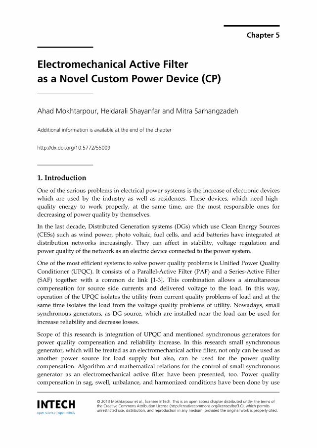
UPQC has composed of two inverters that are connected back to back [2]. One of them is connected to the grid via a parallel transformer and can compensate the current problems (PAF). Another one is connected to the grid via a series transformer and can compensate the voltage problems (SAF). These inverters are controlled for the compensation of the power quality problems instantaneously. Figure 1 shows the general schematic of a UPQC.
Figure 1. General schematic of a UPQC
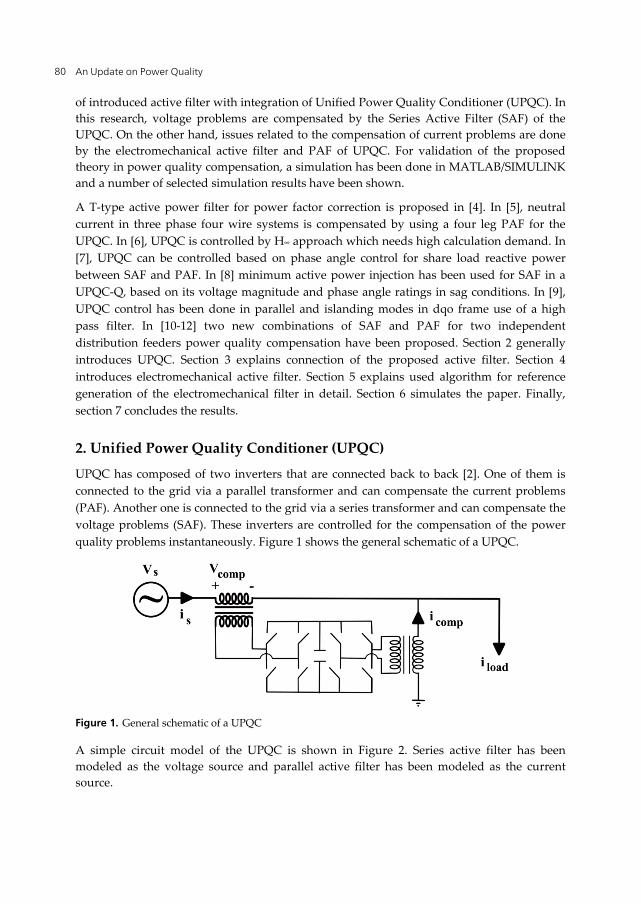
A simple circuit model of the UPQC is shown in Figure 2. Series active filter has been modeled as the voltage source and parallel active filter has been modeled as the current source.
Electromechanical Active Filter as a Novel Custom Power Device (CP) 81
Figure 2. Circuit model of UPQC
3. Connection of Electromechanical Filter
Figure 3, shows schematic of the proposed compensator system. In this research load current harmonics with higher order than 7, has been determined as PAF of UPQC compensator signal. But, load current harmonics with lower order than 7 and reactive power have been compensated by the proposed electromechanical filter.
Figure 3. Proposed compensator system
4. Electromechanical Parallel Active Filter
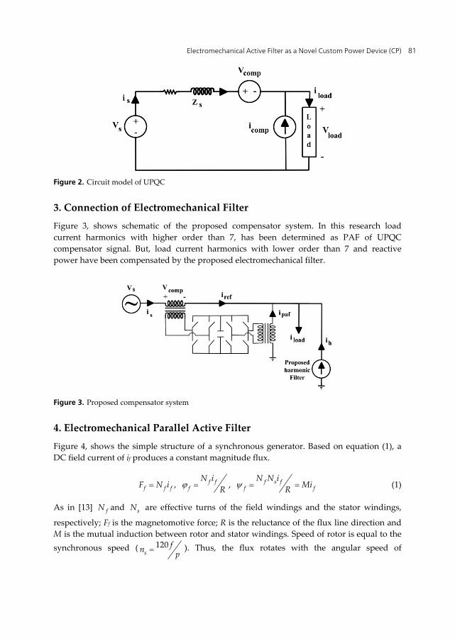
Figure 4, shows the simple structure of a synchronous generator. Based on equation (1), a DC field current of if produces a constant magnitude flux.
, ,f f f s ff f f f f f
N i N N iF N i MiR R (1)
As in [13] fN and sN are effective turns of the field windings and the stator windings,
respectively; Ff is the magnetomotive force; R is the reluctance of the flux line direction and M is the mutual induction between rotor and stator windings. Speed of rotor is equal to the synchronous speed ( 120
sfn p ). Thus, the flux rotates with the angular speed of
An Update on Power Quality 82
260
ss
n . So, stator windings passing flux has been changed as equation (2). It is
assumed that in 0t , direct axis of field and stator first phase windings conform each other.
cos( )s fi M t (2)
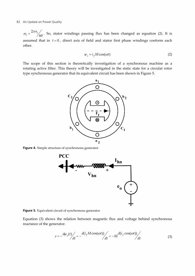
The scope of this section is theoretically investigation of a synchronous machine as a rotating active filter. This theory will be investigated in the static state for a circular rotor type synchronous generator that its equivalent circuit has been shown in Figure 5.
Figure 4. Simple structure of synchronous generator
Figure 5. Equivalent circuit of synchronous generator
Equation (3) shows the relation between magnetic flux and voltage behind synchronous reactance of the generator.
( cos( )) ( cos( ))( ) f fs
d i M t d i td te Mdt dt dt (3)
Electromechanical Active Filter as a Novel Custom Power Device (CP) 83
Based on equation (3), if the field current be a DC current, the stator induction voltage will be a sinusoidal voltage by the amplitude of fM i . But, if the field current be harmonized as
equation (4) then, the flux and internal induction voltage will be as equations (5) and (6), respectively.
sin( )f dc fn fnn
i I I n t (4)
cos( ) [ sin( )] cos( )
1cos( ) [sin(( 1) ) sin(( 1) )]2
f f dc fn fnn
dc fn fn fn
i M t I I n t M t
MI t M I n t n t
(5)
2 2
( 1) ( 1) ( 1) ( 1)2
1[ sin( ) cos( )]2
1 1[ cos( ) cos( )]2 2
o dc f f
f n f n f n f nn
e MI t MI t
MI n n t MI n n t
(6)
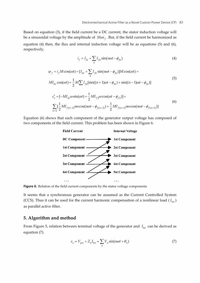
Equation (6) shows that each component of the generator output voltage has composed of two components of the field current. This problem has been shown in Figure 6.
Figure 6. Relation of the field current components by the stator voltage components
It seems that a synchronous generator can be assumed as the Current Controlled System (CCS). Thus it can be used for the current harmonic compensation of a nonlinear load ( hnI ) as parallel active filter.
5. Algorithm and method
From Figure 5, relation between terminal voltage of the generator and hnI can be derived as equation (7).
sin( )o pcc n hn n nn
e V Z I V n t (7)
An Update on Power Quality 84
Where, n is the harmonic order; nZ R jnX is the harmonic impedance of the synchronous generator and connector transformer which are known, PCCV is the point of common coupling voltage and hnI is the compensator current that has been extracted from the control circuit.
If similar frequency components of voltage signal oe in equation (6) and oe in equation (7) set equal, the magnitude and phase angle of the related field current components will be extracted as:
For n=1:
2 2 1 11sin( ) cos( ) sin( )2dc f fMI t MI t V t (8)
2 22 2 2 2 1
1 1[ sin ] [ cos ]2 2dc f f f fMI MI MI V (9)
2 21
1
2 2
1 cos2tan [ ]
1 sin2
f f
dc f f
MI
MI MI
(10)
For simplicity equations (9) and (10) can be rewritten as follows:
2 21 sin2dc f fX MI MI (11)
2 21 cos2 f fY MI (12)
2 2 21X Y V (13)
1X
Y (14)
From the above equations, magnitude and phase of the second component of filed current can result in:
12
11 tan
VX
(15)
2
1tan
tandc
fX MI
X
(16)
Electromechanical Active Filter as a Novel Custom Power Device (CP) 85
2
2
2( )sin
dcf
f
X MII
M
(17)
For n≥2:
( 1) ( 1) ( 1) ( 1)1 1sin sin2 2f n f n f n f nX MI n MI n (18)
( 1) ( 1) ( 1) ( 1)1 1cos cos2 2f n f n f n f nY MI n MI n (19)
21 tan
n
n
VX
(20)
( 1) ( 1)( 1)
( 1) ( 1)
0.5 sintan
tan 0.5 cosf n f n
f nn f n f n
X Mn I
X Mn I
(21)
( 1) ( 1)( 1)
( 1)
2( 0.5 sin )
sinf n f n
f nf n
X Mn II
Mn
(22)
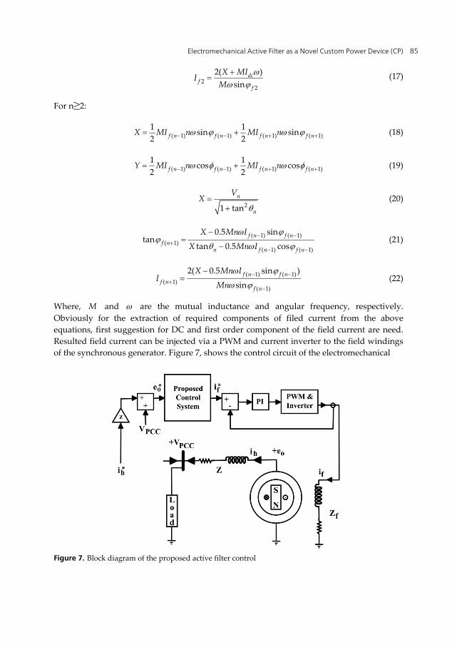
Where, M and are the mutual inductance and angular frequency, respectively. Obviously for the extraction of required components of filed current from the above equations, first suggestion for DC and first order component of the field current are need. Resulted field current can be injected via a PWM and current inverter to the field windings of the synchronous generator. Figure 7, shows the control circuit of the electromechanical
Figure 7. Block diagram of the proposed active filter control
An Update on Power Quality 86
active filter. hI and fI are desired compensator current and calculated field current signal.
Detail of the proposed control circuit can be found in the equations (11) to (22). In the present research controlled voltage source of MATLAB has been used instead of required PWM and inverter. Constant and integrator coefficients in the PI controller have been chosen 1000 and 200, respectively. As mentioned earlier first order load active and reactive powers can be easily attended in the electromechanically compensated share of load current for decrease of SAF and PAF power range of UPQC. This problem can control power flow as well as power quality. In other word it can be possible to use a synchronous generator not only for first order voltage generation but, also for the harmonic compensation too.
6. Results
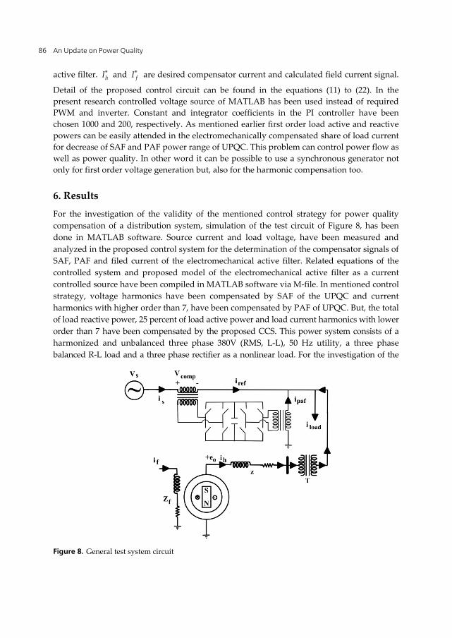
For the investigation of the validity of the mentioned control strategy for power quality compensation of a distribution system, simulation of the test circuit of Figure 8, has been done in MATLAB software. Source current and load voltage, have been measured and analyzed in the proposed control system for the determination of the compensator signals of SAF, PAF and filed current of the electromechanical active filter. Related equations of the controlled system and proposed model of the electromechanical active filter as a current controlled source have been compiled in MATLAB software via M-file. In mentioned control strategy, voltage harmonics have been compensated by SAF of the UPQC and current harmonics with higher order than 7, have been compensated by PAF of UPQC. But, the total of load reactive power, 25 percent of load active power and load current harmonics with lower order than 7 have been compensated by the proposed CCS. This power system consists of a harmonized and unbalanced three phase 380V (RMS, L-L), 50 Hz utility, a three phase balanced R-L load and a three phase rectifier as a nonlinear load. For the investigation of the
Figure 8. General test system circuit
Electromechanical Active Filter as a Novel Custom Power Device (CP) 87
voltage harmonic condition, utility voltages have harmonic and negative sequence components between 0.05 s and 0.2 s. Also, for the investigation of the proposed control strategy in unbalance condition, magnitude of the first phase voltage is increased to the 1.25 pu between 0.05 s and 0.1 s and decreased to the 0.75 pu between 0.15 s to 0.2 s. Table 1, shows the utility voltage harmonic and sequence parameters data and Table 2, shows the load power and voltage parameters. A number of selected simulation results will be showed further.
Voltage Order Sequence Magnitude (pu) Phase Angle (deg) 5 1 0.12 -45 3 2 0.1 0
Table 1. Utility voltage harmonic and sequence parameters data
Load Nominal Power (kVA) Nominal Voltage (RMS, L-L) Linear 10 380V Non linear 5 380V
Table 2. Load power and voltage parameters data
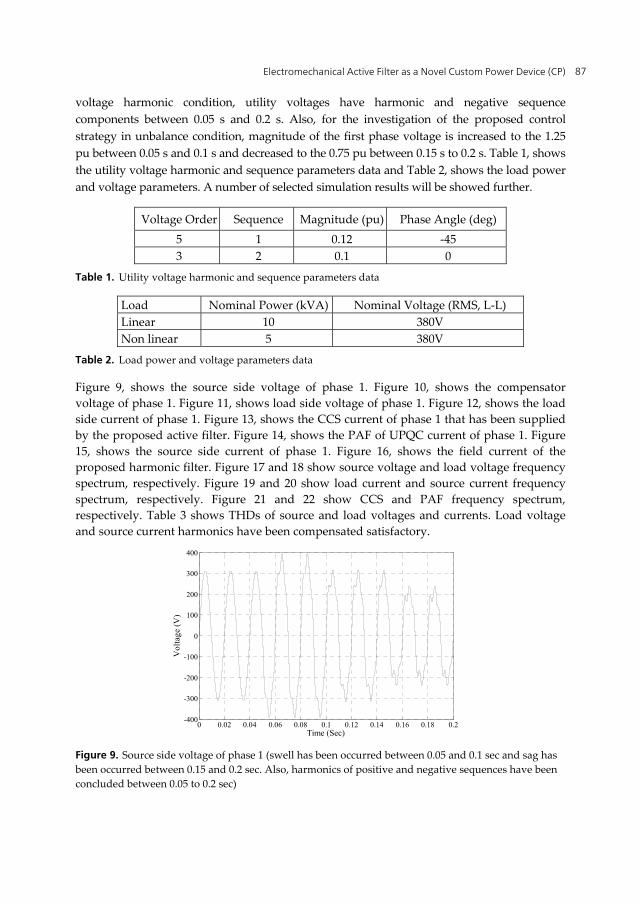
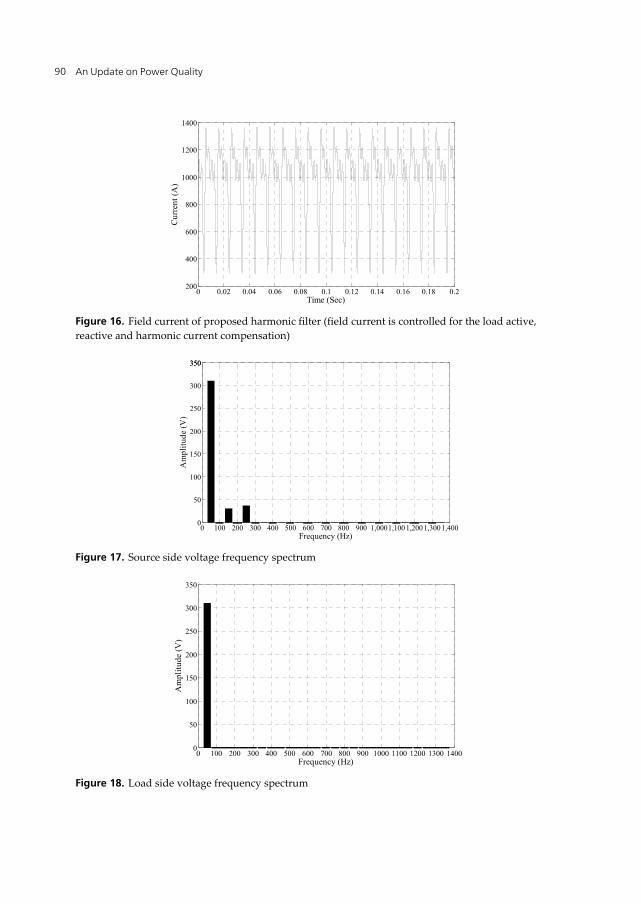
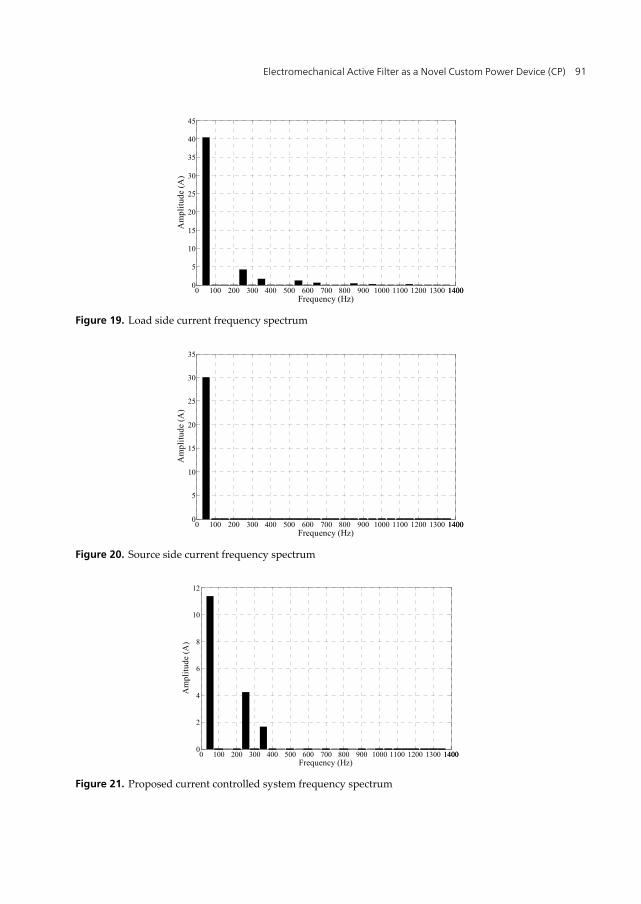
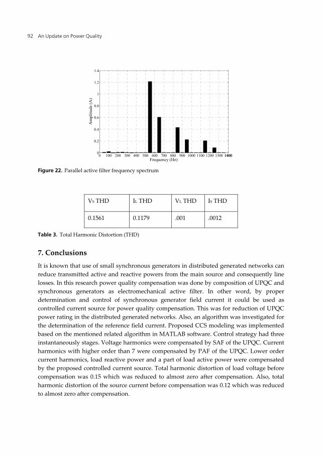
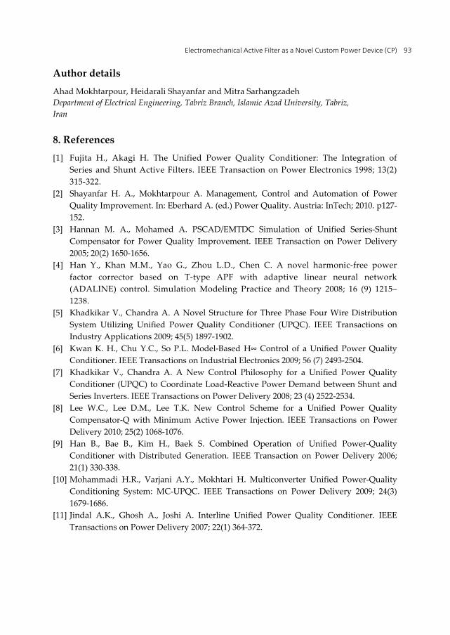
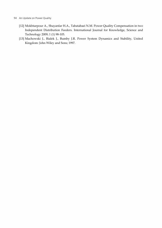
Figure 9, shows the source side voltage of phase 1. Figure 10, shows the compensator voltage of phase 1. Figure 11, shows load side voltage of phase 1. Figure 12, shows the load side current of phase 1. Figure 13, shows the CCS current of phase 1 that has been supplied by the proposed active filter. Figure 14, shows the PAF of UPQC current of phase 1. Figure 15, shows the source side current of phase 1. Figure 16, shows the field current of the proposed harmonic filter. Figure 17 and 18 show source voltage and load voltage frequency spectrum, respectively. Figure 19 and 20 show load current and source current frequency spectrum, respectively. Figure 21 and 22 show CCS and PAF frequency spectrum, respectively. Table 3 shows THDs of source and load voltages and currents. Load voltage and source current harmonics have been compensated satisfactory.
Figure 9. Source side voltage of phase 1 (swell has been occurred between 0.05 and 0.1 sec and sag has been occurred between 0.15 and 0.2 sec. Also, harmonics of positive and negative sequences have been concluded between 0.05 to 0.2 sec)
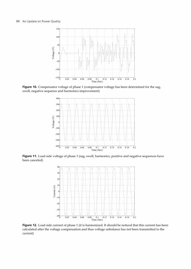
Figure 10. Compensator voltage of phase 1 (compensator voltage has been determined for the sag, swell, negative sequence and harmonics improvement)
Figure 11. Load side voltage of phase 1 (sag, swell, harmonics, positive and negative sequences have been canceled)
Figure 12. Load side current of phase 1 (it is harmonized. It should be noticed that this current has been calculated after the voltage compensation and thus voltage unbalance has not been transmitted to the current)
Electromechanical Active Filter as a Novel Custom Power Device (CP) 89
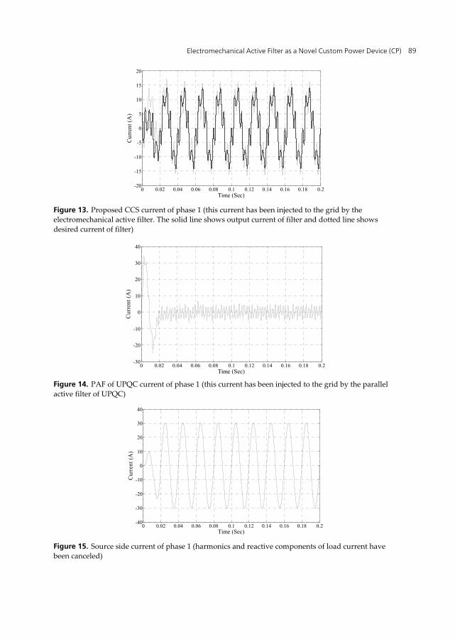
Figure 13. Proposed CCS current of phase 1 (this current has been injected to the grid by the electromechanical active filter. The solid line shows output current of filter and dotted line shows desired current of filter)
Figure 14. PAF of UPQC current of phase 1 (this current has been injected to the grid by the parallel active filter of UPQC)
Figure 15. Source side current of phase 1 (harmonics and reactive components of load current have been canceled)
Figure 22. Parallel active filter frequency spectrum
VS THD IL THD VL THD IS THD
0.1561 0.1179 .001 .0012
Table 3. Total Harmonic Distortion (THD)
7. Conclusions
It is known that use of small synchronous generators in distributed generated networks can reduce transmitted active and reactive powers from the main source and consequently line losses. In this research power quality compensation was done by composition of UPQC and synchronous generators as electromechanical active filter. In other word, by proper determination and control of synchronous generator field current it could be used as controlled current source for power quality compensation. This was for reduction of UPQC power rating in the distributed generated networks. Also, an algorithm was investigated for the determination of the reference field current. Proposed CCS modeling was implemented based on the mentioned related algorithm in MATLAB software. Control strategy had three instantaneously stages. Voltage harmonics were compensated by SAF of the UPQC. Current harmonics with higher order than 7 were compensated by PAF of the UPQC. Lower order current harmonics, load reactive power and a part of load active power were compensated by the proposed controlled current source. Total harmonic distortion of load voltage before compensation was 0.15 which was reduced to almost zero after compensation. Also, total harmonic distortion of the source current before compensation was 0.12 which was reduced to almost zero after compensation.
Electromechanical Active Filter as a Novel Custom Power Device (CP) 93
Author details
Ahad Mokhtarpour, Heidarali Shayanfar and Mitra Sarhangzadeh Department of Electrical Engineering, Tabriz Branch, Islamic Azad University, Tabriz, Iran
8. References
[1] Fujita H., Akagi H. The Unified Power Quality Conditioner: The Integration of Series and Shunt Active Filters. IEEE Transaction on Power Electronics 1998; 13(2) 315-322.
[2] Shayanfar H. A., Mokhtarpour A. Management, Control and Automation of Power Quality Improvement. In: Eberhard A. (ed.) Power Quality. Austria: InTech; 2010. p127-152.
[3] Hannan M. A., Mohamed A. PSCAD/EMTDC Simulation of Unified Series-Shunt Compensator for Power Quality Improvement. IEEE Transaction on Power Delivery 2005; 20(2) 1650-1656.
[4] Han Y., Khan M.M., Yao G., Zhou L.D., Chen C. A novel harmonic-free power factor corrector based on T-type APF with adaptive linear neural network (ADALINE) control. Simulation Modeling Practice and Theory 2008; 16 (9) 1215–1238.
[5] Khadkikar V., Chandra A. A Novel Structure for Three Phase Four Wire Distribution System Utilizing Unified Power Quality Conditioner (UPQC). IEEE Transactions on Industry Applications 2009; 45(5) 1897-1902.
[6] Kwan K. H., Chu Y.C., So P.L. Model-Based H∞ Control of a Unified Power Quality Conditioner. IEEE Transactions on Industrial Electronics 2009; 56 (7) 2493-2504.
[7] Khadkikar V., Chandra A. A New Control Philosophy for a Unified Power Quality Conditioner (UPQC) to Coordinate Load-Reactive Power Demand between Shunt and Series Inverters. IEEE Transactions on Power Delivery 2008; 23 (4) 2522-2534.
[8] Lee W.C., Lee D.M., Lee T.K. New Control Scheme for a Unified Power Quality Compensator-Q with Minimum Active Power Injection. IEEE Transactions on Power Delivery 2010; 25(2) 1068-1076.
[9] Han B., Bae B., Kim H., Baek S. Combined Operation of Unified Power-Quality Conditioner with Distributed Generation. IEEE Transaction on Power Delivery 2006; 21(1) 330-338.
[10] Mohammadi H.R., Varjani A.Y., Mokhtari H. Multiconverter Unified Power-Quality Conditioning System: MC-UPQC. IEEE Transactions on Power Delivery 2009; 24(3) 1679-1686.
[11] Jindal A.K., Ghosh A., Joshi A. Interline Unified Power Quality Conditioner. IEEE Transactions on Power Delivery 2007; 22(1) 364-372.
An Update on Power Quality 94
[12] Mokhtarpour A., Shayanfar H.A., Tabatabaei N.M. Power Quality Compensation in two Independent Distribution Feeders. International Journal for Knowledge, Science and Technology 2009; 1 (1) 98-105.
[13] Machowski J., Bialek J., Bumby J.R. Power System Dynamics and Stability, United Kingdom: John Wiley and Sons; 1997.