www.tridonic.com 1 Subject to change without notice. Data sheet 03/12-704-4 Electronic ballasts for high-intensity discharge lamps Indoor HI Product description • For metal halide lamps • Also for mobile luminaires with connectors • Pulse packets for increased ignition energy (pulseCONTROL technology) • Switching possible via mains or powerless via the digital interface • Noise-free precise control via DALI or DSI signal • On/off switching via DALI/DSI signal • Fault reporting in DALI mode • With patented circuit elements • Flicker-free light • Colour stability thanks to constant power • Guaranteed long life • No acoustic resonance • Safety shutdown if a lamp is faulty or missing • Greatly reduced reignition time • Hardly any EMC interference in the ignition phase • Automatic shutdown on overheating • Screw terminals: ≤ 1.5 mm² for stranded wire, ≤ 2.5 mm² for solid wire • Lower section of casing made of steel • Upper section of casing made of Makrolon, VO material, black Technical data Mains voltage range 220 – 240 V AC voltage range 198 – 254 V DC voltage range 153 – 320 V Mains frequency 0 / 50 / 60 Hz Max. ignition voltage 5 kVp Operating frequency 145 Hz Type of protection IP20 È Standards, page 2 Wiring diagrams and installation examples, page 2 PCI FOX B011 PCI PRO, built-in applications HI 88,5 – 92,5 100 4,5 4,5 75 63,5 – 67,5 28 128,5 – 132,5 140 4,5 4,5 75 63,5 – 67,5 31 158,5 – 162,5 170 4,5 4,5 75 63,5 – 67,5 31 Ordering data Type Article number Packaging, carton Packaging, pallet Weight per pcs. For luminaires with 1 lamp PCI 0020 FOX B011 86458340 15 pieces 600 pieces 0.19 kg PCI 0035 FOX B011 86458341 15 pieces 600 pieces 0.19 kg PCI 0070 FOX B011 86458342 15 pieces 600 pieces 0.25 kg PCI 0150 FOX B011 86458343 15 pieces 600 pieces 0.37 kg Specific technical data Lamp wattage Lamp type Type Article number Dimensions L x W x H Lamp power Circuit power1 EEI Efficiency Current at 50 Hz 230 V λ at 50 Hz 230 V Max. cable length to lamp tc point max. Ambient temperature ta tc/ta for ≥ 50,000 h For luminaires with 1 lamp 1 x 20 W HI PCI 0020 FOX B011 86458340 100 x 75 x 28 mm 20 W 24.5 W A2 > 84 % 0.10 A 0.95 1.5 m / 120 pF 80 °C -25 ... +55 °C 80/55 °C 1 x 35 W HI PCI 0035 FOX B011 86458341 100 x 75 x 28 mm 39 W 45.0 W A2 > 87 % 0.20 A 0.97 1.5 m / 120 pF 80 °C -25 ... +50 °C 80/50 °C 1 x 70 W HI PCI 0070 FOX B011 86458342 140 x 75 x 31 mm 72 W 80.0 W A2 > 89 % 0.35 A 0.97 1.5 m / 120 pF 80 °C -25 ... +50 °C 80/50 °C 1 x 150 W HI PCI 0150 FOX B011 86458343 170 x 75 x 31 mm 147 W 160.0 W A2 > 91 % 0.70 A 0.97 1.5 m / 120 pF 80 °C -25 ... +50 °C 80/50 °C 1 At ta = 25 °C.
Transcript
www.tridonic.com 1Subject to change without notice.
Data sheet 03/12-704-4
Electronic ballasts for high-intensity discharge lampsIndoor HI
Product description
•For metal halide lamps
•Also for mobile luminaires with connectors
•Pulse packets for increased ignition energy
(pulseCONTROL technology)
•Switching possible via mains or powerless via the digital interface
•Noise-free precise control via DALI or DSI signal
•On/off switching via DALI/DSI signal
•Fault reporting in DALI mode
•With patented circuit elements
•Flicker-free light
•Colour stability thanks to constant power
•Guaranteed long life
•No acoustic resonance
•Safety shutdown if a lamp is faulty or missing
•Greatly reduced reignition time
•Hardly any EMC interference in the ignition phase
•Automatic shutdown on overheating
•Screw terminals: ≤ 1.5 mm² for stranded wire,
≤ 2.5 mm² for solid wire
•Lower section of casing made of steel
•Upper section of casing made of Makrolon, VO material, black
Technical dataMains voltage range 220 – 240 V
AC voltage range 198 – 254 V
DC voltage range 153 – 320 V
Mains frequency 0 / 50 / 60 Hz
Max. ignition voltage 5 kVp
Operating frequency 145 Hz
Type of protection IP20
ÈStandards, page 2
Wiring diagrams and installation examples, page 2
PCI FOX B011PCI PRO, built-in applications
HI
88,5 – 92,5
1004,5
4,5
7563
,5 –
67,
528
128,5 – 132,5
1404,5
4,5
7563
,5 –
67,
531
158,5 – 162,5
1704,5
4,5
7563
,5 –
67,
531
Ordering data
Type Article number Packaging, carton
Packaging, pallet
Weight per pcs.
For luminaires with 1 lamp
PCI 0020 FOX B011 86458340 15 pieces 600 pieces 0.19 kg
PCI 0035 FOX B011 86458341 15 pieces 600 pieces 0.19 kg
PCI 0070 FOX B011 86458342 15 pieces 600 pieces 0.25 kg
PCI 0150 FOX B011 86458343 15 pieces 600 pieces 0.37 kg
Specific technical dataLamp
wattageLamp type
Type Article number Dimensions L x W x H
Lamp power
Circuit power1
EEI Efficiency Current at 50 Hz 230 V
λ at 50 Hz 230 V
Max. cablelength to lamp
tc point max.
Ambient temperature ta
tc/ta for ≥ 50,000 h
For luminaires with 1 lamp1 x 20 W HI PCI 0020 FOX B011 86458340 100 x 75 x 28 mm 20 W 24.5 W A2 > 84 % 0.10 A 0.95 1.5 m / 120 pF 80 °C -25 ... +55 °C 80/55 °C
1 x 35 W HI PCI 0035 FOX B011 86458341 100 x 75 x 28 mm 39 W 45.0 W A2 > 87 % 0.20 A 0.97 1.5 m / 120 pF 80 °C -25 ... +50 °C 80/50 °C
1 x 70 W HI PCI 0070 FOX B011 86458342 140 x 75 x 31 mm 72 W 80.0 W A2 > 89 % 0.35 A 0.97 1.5 m / 120 pF 80 °C -25 ... +50 °C 80/50 °C
1 x 150 W HI PCI 0150 FOX B011 86458343 170 x 75 x 31 mm 147 W 160.0 W A2 > 91 % 0.70 A 0.97 1.5 m / 120 pF 80 °C -25 ... +50 °C 80/50 °C1 At ta = 25 °C.
www.tridonic.com 2Subject to change without notice.
Data sheet 03/12-704-4
Electronic ballasts for high-intensity discharge lampsIndoor HI
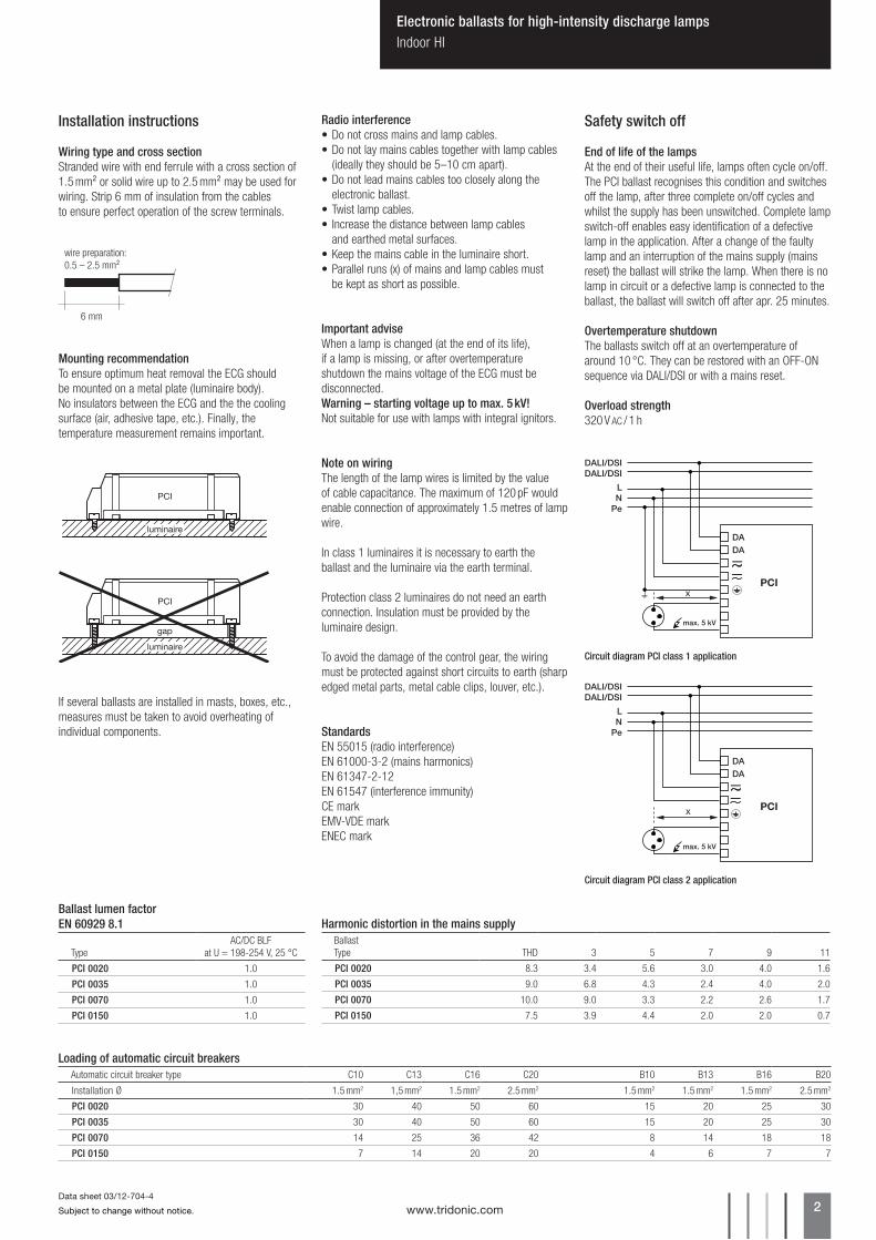
Installation instructions
Wiring type and cross sectionStranded wire with end ferrule with a cross section of 1.5 mm² or solid wire up to 2.5 mm² may be used for wiring. Strip 6 mm of insulation from the cables to ensure perfect operation of the screw terminals.
and earthed metal surfaces.•Keepthemainscableintheluminaireshort.•Parallelruns(x)ofmainsandlampcablesmust
be kept as short as possible.
Note on wiringThe length of the lamp wires is limited by the value of cable capacitance. The maximum of 120 pF would enable connection of approximately 1.5 metres of lamp wire.
In class 1 luminaires it is necessary to earth the ballast and the luminaire via the earth terminal.
Protection class 2 luminaires do not need an earth connection. Insulation must be provided by the luminaire design.
To avoid the damage of the control gear, the wiring must be protected against short circuits to earth (sharp edged metal parts, metal cable clips, louver, etc.).
Important adviseWhen a lamp is changed (at the end of its life), if a lamp is missing, or after overtemperature shutdown the mains voltage of the ECG must be disconnected.Warning – starting voltage up to max. 5 kV!Not suitable for use with lamps with integral ignitors.
Safety switch off
End of life of the lampsAt the end of their useful life, lamps often cycle on/off. The PCI ballast recognises this condition and switches off the lamp, after three complete on/off cycles and whilst the supply has been unswitched. Complete lamp switch-off enables easy identification of a defective lamp in the application. After a change of the faulty lamp and an interruption of the mains supply (mains reset) the ballast will strike the lamp. When there is no lamp in circuit or a defective lamp is connected to the ballast, the ballast will switch off after apr. 25 minutes.
Overtemperature shutdownThe ballasts switch off at an overtemperature of around 10 °C. They can be restored with an OFF-ON sequence via DALI/DSI or with a mains reset.
Overload strength320 V AC / 1 h
DADA
PCI
max. 5 kV
LN
Pe
DALI/DSIDALI/DSI
Circuit diagram PCI class 2 application
DALI/DSIDALI/DSI
DADA
LN
Pe
PCI
max. 5 kV
Mounting recommendationTo ensure optimum heat removal the ECG should be mounted on a metal plate (luminaire body). No insulators between the ECG and the the cooling surface (air, adhesive tape, etc.). Finally, the temperature measurement remains important.
If several ballasts are installed in masts, boxes, etc., measures must be taken to avoid overheating of individual components.
luminaire
PCI
luminaire
gap
PCI
6 mm
wire preparation:0.5 – 2.5 mm²
Loading of automatic circuit breakersAutomatic circuit breaker type C10 C13 C16 C20 B10 B13 B16 B20
Harmonic distortion in the mains supplyBallastType THD 3 5 7 9 11
PCI 0020 8.3 3.4 5.6 3.0 4.0 1.6
PCI 0035 9.0 6.8 4.3 2.4 4.0 2.0
PCI 0070 10.0 9.0 3.3 2.2 2.6 1.7
PCI 0150 7.5 3.9 4.4 2.0 2.0 0.7
Ballast lumen factorEN 60929 8.1
TypeAC/DC BLF
at U = 198-254 V, 25 °C
PCI 0020 1.0
PCI 0035 1.0
PCI 0070 1.0
PCI 0150 1.0
www.tridonic.com 3Subject to change without notice.
Data sheet 03/12-704-4
Electronic ballasts for high-intensity discharge lampsIndoor HI
Control input (DA)Digital DALI/DSI signal can be wired on the terminals DA.
Digital signal DALI/DSIThe control input is non-polar and protected against accidental connection with a mains voltage up to 264 V. The control signal is not SELV. Control cable should be installed in accordance with the require-ments of low voltage installations. Different functions depending on each module.
Queriesvia DALI standard:•Lamp wattage (values yes/no)•Lamp error (values yes/no)
via eDALI:•Lamp type•Device type•Article number•Production date•Serial number•Software version•Commissioning
OEM Memory BankThe customer can store additional luminaire informa-tion in the ECG (Memory Bank 1), such as luminaire type and article number. Data is written to Memory Bank 1 in accordance with DALI standard IEC 62368.
Because of the special characteristics of HID light sources, PCI FOX ballasts (Device Type 2) cannot be addressed in the same way as conventional DALI ballasts for fluorescent or halogen lamps for example. For visualisation dur-ing the grouping phase the HID lamps must remain switched off before and during the addressing phase as they can only be properly ignited in the cold state. Dimmed operation of these lamps is not recommended, which also calls for different handling during commissioning.
Tridonic recommends configTOOL ≥ V1.5 software for commissioning PCI FOX ballasts (download from www.tridonic.com → Services → Download → Software).
IMPORTANT: Other DALI controllers can only be used for commissioning if they handle DALI Device Type 2 units appropriately (see Requirements of control products).
Overview – commissioning cycle with configTOOL ≥ V1.5
Installation instructions Commissioning of PCI FOX ballasts
Commissioning comparison table
DALI HID ballast PCI FOX
Standard DALI ballast e.g. PCA Excel one4all
Before commissioning the instal-lation
Devices must have been switched off for at least 10 minutes!
–
Initialisation and addressing phase
Devices remain switched off
• Devices fade to minimum value• On successful addressing the devices fade
up to 100 %• At the end of the addressing phase the
devices fade down to the minimum valueVisualisation in the grouping phase
• Selected device starts the lamp at 100 %• If a different device is selected the previously
selected device switches off with a maximum delay of 10 s
Visualisation/grouping is not possible with hot HID lamps!
• Selected device fades from minimum value to 100 %
• If a different device is selected the previously selected device fades to the minimum value
Operation Devices can be controlled/operated with other DALI/DSI control products
Devices can be controlled/operated with other DALI/DSI control products
0%
100%
10 min.
lamp first device lamp second device
light
start
first PCI FOX device second PCI FOX device
2.Initialization/
addressing phase
1.Cooling phase
3.Grouping phase
4.Operation
endfirst device selected(Recall Max.)
second device selected(Recall Max.)
www.tridonic.com 4Subject to change without notice.
Data sheet 03/12-704-4
Electronic ballasts for high-intensity discharge lampsIndoor HI
Realisation with Tridonic controls
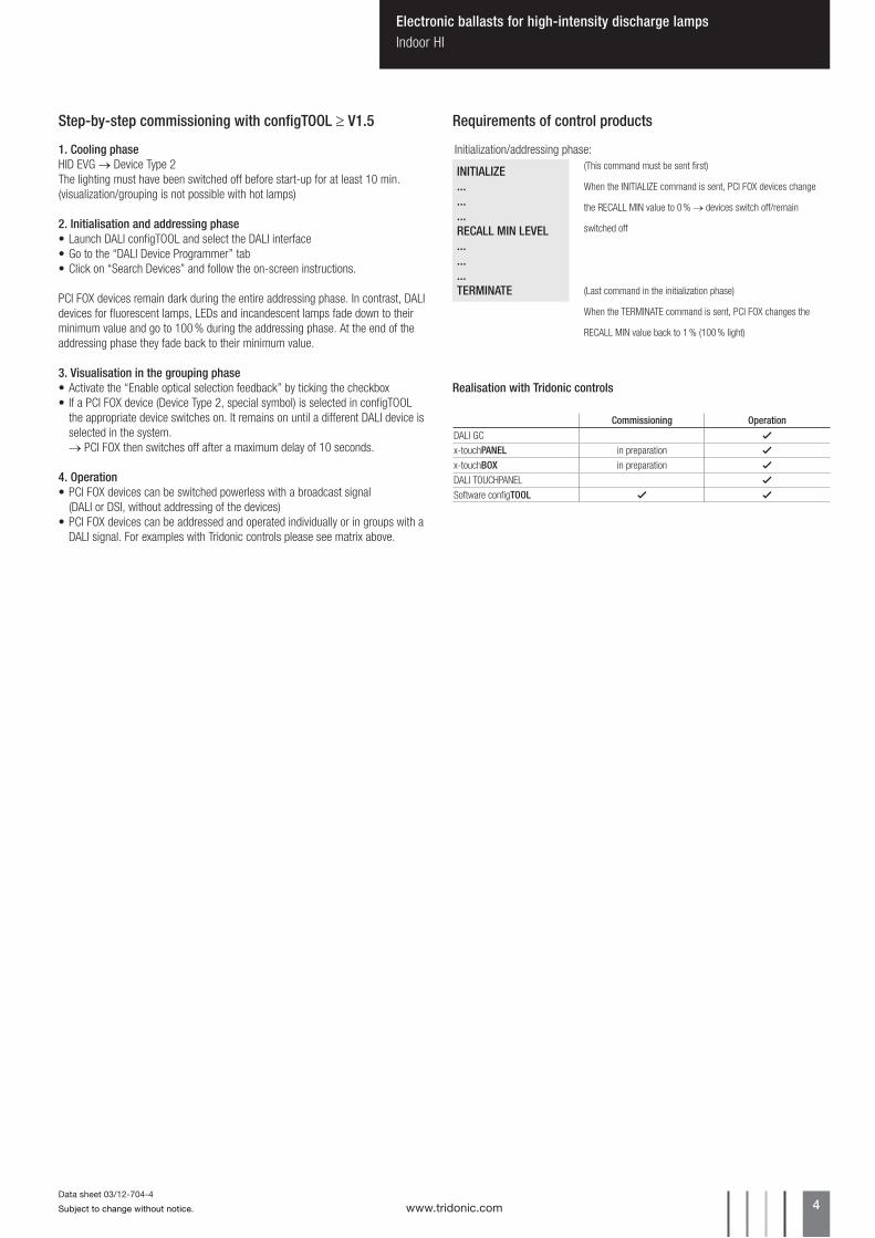
INITIALIZE.........RECALL MIN LEVEL.........TERMINATE
(This command must be sent first)
When the INITIALIZE command is sent, PCI FOX devices change
the RECALL MIN value to 0 % → devices switch off/remain
switched off
(Last command in the initialization phase)
When the TERMINATE command is sent, PCI FOX changes the
RECALL MIN value back to 1 % (100 % light)
1. Cooling phaseHID EVG → Device Type 2The lighting must have been switched off before start-up for at least 10 min. (visualization/grouping is not possible with hot lamps)
2. Initialisation and addressing phase•Launch DALI configTOOL and select the DALI interface•Go to the “DALI Device Programmer” tab•Click on “Search Devices” and follow the on-screen instructions.
PCI FOX devices remain dark during the entire addressing phase. In contrast, DALI devices for fluorescent lamps, LEDs and incandescent lamps fade down to their minimum value and go to 100 % during the addressing phase. At the end of the addressing phase they fade back to their minimum value.
3. Visualisation in the grouping phase•Activate the “Enable optical selection feedback” by ticking the checkbox• If a PCI FOX device (Device Type 2, special symbol) is selected in configTOOL
the appropriate device switches on. It remains on until a different DALI device is selected in the system. → PCI FOX then switches off after a maximum delay of 10 seconds.
4. Operation•PCI FOX devices can be switched powerless with a broadcast signal
(DALI or DSI, without addressing of the devices)•PCI FOX devices can be addressed and operated individually or in groups with a
DALI signal. For examples with Tridonic controls please see matrix above.
Step-by-step commissioning with configTOOL ≥ V1.5 Requirements of control products
Initialization/addressing phase:
Commissioning OperationDALI GC Gx-touchPANEL in preparation Gx-touchBOX in preparation GDALI TOUCHPANEL GSoftware configTOOL G G


![D HPS 2 Lansing Lighting.ppt [Read-Only] · 2016-02-26 · lamps. – For T8 Lamps: use the latest “High efficiency electronic” ballasts – For T-8 lamps, investigate “low](https://static.documents.pub/doc/80x56/5e76d30d1f12fa5fad13929e/d-hps-2-lansing-read-only-2016-02-26-lamps-a-for-t8-lamps-use-the-latest.jpg)


