NASA-CR-197170 NASw-4435 "'I/ -7'2 - _f S'''f I,) /_D '/ Electronic Communications from Halo Orbit ,.o N I Z 0 U e- :X:O C wu. I-.-_ ._ _Z • uJ C'J _ Z O_C-- I --,c_ _Zv _0 Z; ..Jc_ u_, N ,0 0 0 Aerospace Engineering 401A & 401B The Pennsylvania State University 1993-94 Sponsored by: NASA/Universities Space Research Association Advance Design Program
Transcript
NASA-CR-197170
NASw-4435
"'I/ -7'2 - _f S'''f
I,) /_D '/
Electronic Communications fromHalo Orbit
,.oN
I
Z
0
Ue-
:X:O C
wu.
I-.-_ .__Z •uJ C'J _
Z
O_C--
I --,c__Zv
_0
Z; ..Jc_ u_,
N
,0
00 Aerospace Engineering 401A & 401B
The Pennsylvania State University
1993-94
Sponsored by:
NASA/Universities Space Research AssociationAdvance Design Program
List of Contributors
Systems Integration
Jason Borrelli
Bryan CooleyMarcy Debole
Lance HrivnakKenneth Nielsen
Gary SangmeisterMatthew Wolfe
Command and Data Handling
Adam Lash
Gary SangmeisterShane WilcoxMichael Witt
Communications
David Davis
Christopher FryeElana HammondKenneth Nielsen
Geoffrey Uy
Guidance, Navigation, and Control
Sheri Coates
Bryan CooleyJamie CopelandWilliam Scheetz
Andy Staugler
Propulsion
Jason Borrelli
John NagyBrent Paul
Richard SaylorAlfred Sullivan
Structures/Launch Vehicle
Matthew HykesJustin Knavel
Brian Shaw
Frank ShelbyMatthew Wolfe
Thermal Control
Marcy DeboleGary Mego
Tracie TepkeJohn Vantuno
Instructors
Dr. Robert G. Melton
Dr. Roger C. Thompson
Teaching Assistant
Thomas F. Starchville Jr.
Power
John FreemanLance HrivnakJonathan Rader
Patrick TamburriGrant Waltz
NASA Mentor
Kurt Hack, NASA Lewis
Project ECHO: Electronic Communications from Halo Orbit
EXECUTIVE SUMMARY
The Pennsylvania State UniversityDepartment of Aerospace Engineering
University Park, Pennsylvania
Dr. Robert G. Melton and Dr. Roger C. ThompsonThomas F. Starchville Jr., Teaching Assistant
Jason Borrelli, Bryan Cooley, Marcy Debole, Lance Hrivnak,Ken Nielsen, Gary Sangmeister, Matt Wolfe
Abstract
The design of a communications relay to provideconstant access between the Earth and the far side ofthe Moon is presented. Placement of the relay in ahalo orbit about the L2 Earth-Moon Lagrange pointallows the satellite to maintain constant simultaneouscommunication between Earth and scientific payloadson the far side of the Moon. The requirements ofNASA's Discovery-class missions adopted andmodified for this design are: total project cost shouldnot exceed $150 million excluding launch costs,launch must be provided by Delta-class vehicle, andthe satellite should maintain an operational lifetime of10 to 15 years.
The spacecraft will follow a transfer trajectory tothe L2 point, after launch by a Delta II 7925 vehiclein 1999. Low-level thrust is used for injection into astationkeeping-free halo orbit once the spacecraftreaches the L2 point. The shape of this halo orbit ishighly elliptical with the maximum excursion fromthe L2 point being 35000 km.
A spun section and despun section connectedthrough a bearing and power transfer assembly(BAPTA) compose the structure of the spacecraft.Communications equipment is placed on the despunsection to provide for a stationary dual parabolicoffset-feed array antenna system. The dual system isnecessary to provide communications coverageduring portions of maximum excursion on the haloorbit. Transmissions to the NASA Deep SpaceNetwork 34 m antenna include six channels (colorvideo, two voice, scientific data from lunar payloads,satellite housekeeping and telemetry, and uplinkedcommands) using the S- and X-bands. Fourradioisotope thermoelectric generators (RTG's)provide a total of 1360 W to power onboard systemsand any two of the four Hughes 13 cm ion thrusters atonce. Output of the ion thrusters is approximately17.8 mN each with xenon as the propellant. Presenceof torques generated by solar pressure on the antenna
dish require the addition of a "skirt" extending fromthe spun section of the satellite for balance. Totalmass of the satellite is approximately 900 kg at a costof $130 million FY99.
Mission Objective
The objective of Project ECHO (ElectronicCommunications from Halo Orbit) is to provide acontinuous communications link between Earth andthe far side of the Moon. The spacecraft will providereal-time or delayed transfer of information,telemetry, and voice/video data.
Background
This satellite will provide the link necessary tocommunicate with the Moon's far side. The projectwill allow for the exploration and utilization of the farside of the Moon by establishing a communicationslink to scientific outposts, mining operations, lunarrovers, or exploration probes. The spacecraft will bein halo orbit about the Earth-Moon Lagrange point L2(located on the Earth-Moon line approximately64,500 km beyond the Moon's center) and willmaintain an uninterrupted line-of-sight with both theEarth and the Moon. Development of Project ECHOis restricted by modified NASA Discovery-classmission parameters: 1) total cost must not exceed$150 million (excluding launch vehicle), 2) launchmust be achieved by a Delta-class vehicle, and 3) thedesign lifetime must be greater than 10 years.
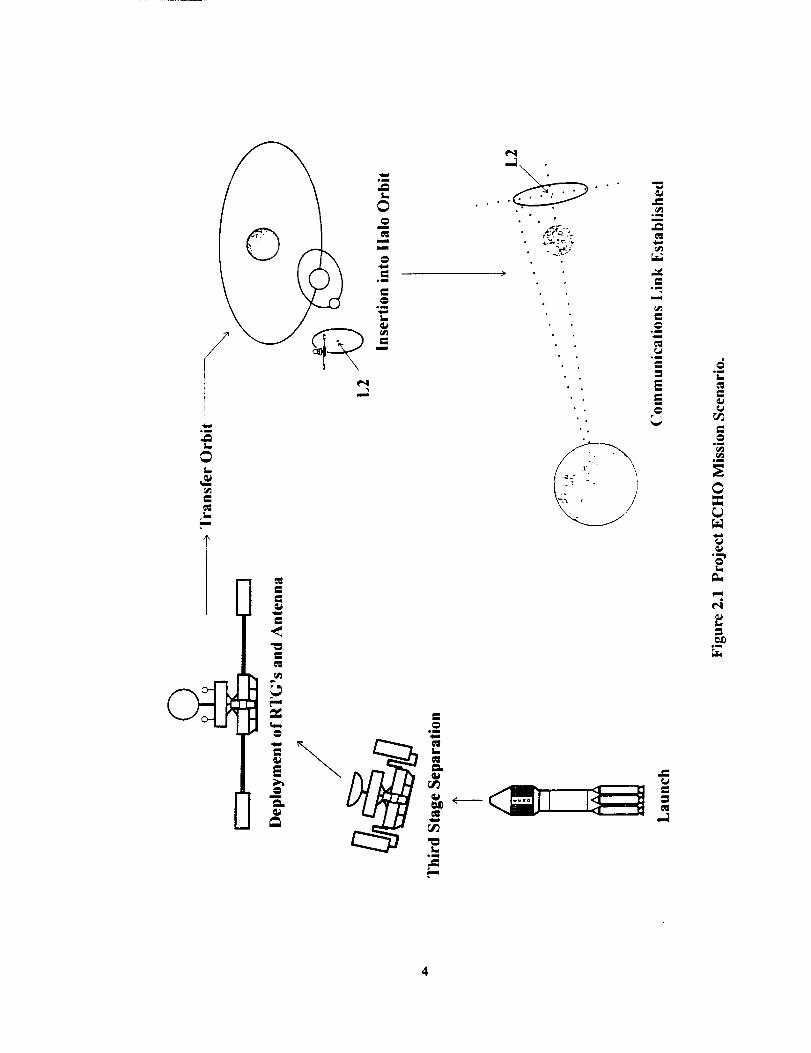
Mission Scenario
Launch will occur at Cape Canaveral, Florida in1999 via a Delta II 7925. This vehicle contains threestages with a payload assist module (PAM)comprising the third stage. After final separation, thesatellite is placed on a transfer trajectory to the L2point and the entire spacecraft will have a spin rate of
ii
45rpm.Deployment of the RTG's will take place 60minutes after launch and will reduce the spacecraft'sspin rate to 9.4 rpm. Despinning of the despunsection will then take place and raise the spunsection's rate to 9.7 rpm. Stabilization of the satelliteonce in the halo orbit is obtained by using thrusters toincrease the spun section's spin rate to 35 rpm.
The parabolic antenna will also be deployedduring the transfer trajectory, however, twin dipoleantennas will provide communications while in
transit to avoid problems in pointing the parabolicdish. After arrival at the L2 point, the spacecraftcontinues toward injection into a halo orbit using alow-thrust spiral. A non-optimal, zero-thrust transfertrajectory from Earth to L2 was found. Thespacecraft's ion thrusters are required for the patchedtrajectory from L2 to Halo. This event sequence isillustrated in Figure 1.
Deployment of RTG's and Antenna
Third Stage Separation
T
Launch
-, Transfer Orbit
12
Insertion into Ilalo Orbit
.. \ . .
Communications Link Established
Figure 1 Project ECHO Mission Scenario.
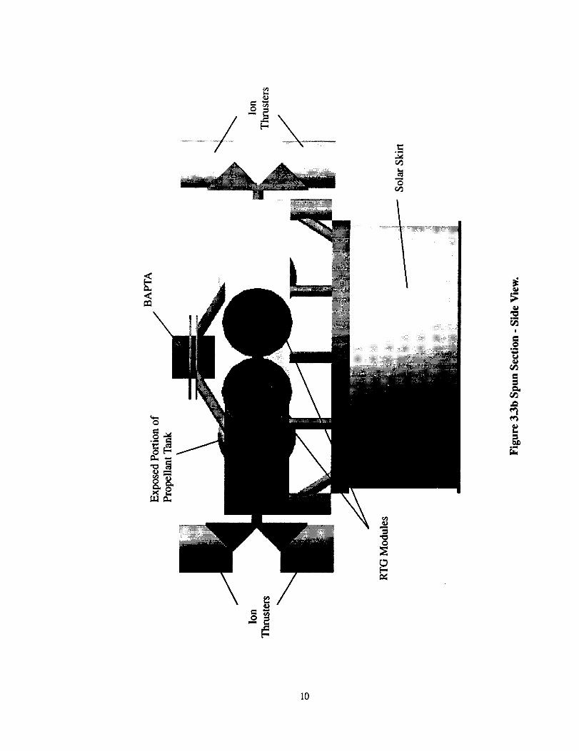
Structures and Launch Vehicle
The structure of the satellite will be composed ofa despun and a spun section connected through aBearing and Power Transfer Assembly (BAPTA).Figure 2 shows the overall configuration of ProjectECHO. The spun section, shown in Figure 3, is acombination of a truss and semi-monocoquestructure. The truss members will be made from A1
7075-T6, and will carry the axial and lateral loads.All axial loads induced during launch will betransferred through the Payload Attach Fitting (PAF)into the third stage of the launch vehicle. The skin,
made of A! 6061-T6, will help to carry torsionalloads and act as a micrometeoroid shield for the
sensitive components.As required by the mission parameters, a Delta II
7925 launch vehicle will be used. The 2.9 mdiameter fairing will be used since its mass is lessthan the 3.0 m diameter fairing and therefore allowsfor a greater spacecraft mass. For a maximum massof 1200 kg, ECHO will utilize the 3712C PAF tointerface the satellite to the launch vehicle, which
contains the control systems for the third stage of thelaunch vehicle.
iii
Despun
BAPTA
Spun Section
RTGs
Parabolic Antenna
Offset Feed
Subreflectors
Ion
Thrusters
Solar Skirt
RTGs
Figure 2 lsotropic view of the ECHO spacecraft.
BAPTA
Power Processin
Units
mn Section
Ion
Thrusters
Ion
Thrusters
Xenon Propellant Tanks
Figure 3 Cut-away view of the spun section.
iv
Power
The electrical power system (EPS) design wasdriven by the following requirements: the EPS mustgenerate, distribute, and regulate all electrical powerwithin the ECHO spacecraft and provide enoughpower for 2 ion thrusters in addition to the other
components.ECHO's electrical power system has several
main components. First, a radioisotopethermoelectric generator (RTG) will be used togenerate the 1280 Watts necessary to power thespacecraft during maximum steady-state powerconsumption. The General Electric MOD-RTG hasbeen selected for this purpose. Power distributionwill be via a standard 28 V-dc power bus located inthe spacecraft's spun section, with electromechanicalswitches providing circuit isolation for unusedcomponents. A decentralized regulation scheme willbe utilized on the bus, and power transmission fromthe RTG to the bus will be through a direct energytransfer system relying on shunt resistors to dissipateunused power. The specific power regulation will beaccomplished with the Arnold Magnetics EL-2000series of DC-DC power converters.
Thermal
The requirement of the thermal subsystem is tomaintain all of the components of the spacecraftwithin their operational temperature ranges: 0 "C to40 "C for the despun section and 10 "C to 30 "C forthe spun section. Because ECHO is powered byRTGs, a high thermal flux will impinge on thesatellite. This heat, along with that radiated from theSun, Earth, and internal components provideminimum and maximum temperature rangesexperienced by the spacecraft in the halo orbit of-31 "C to 31 "C for the despun section and -44 'C to25 "C for the spun section. The worst case coldtemperatures are well below the lower limits allowedfor the operation of the components.
Though a completely passive system had beenthe ultimate goal for this system, it will not bepossible for ECHO. The components necessary tobring the temperatures into the required ranges will
be silverized Teflon thermal coating on the top of thedespun section and bottom of the spun section andheaters in both sections. The activation and
deactivation of the heaters will be regulated by thecommand and data handling subsystem usingreadings from temperature sensors placed throughoutthe spacecraft.
In addition to the system that regulates thethermal environment of ECHO in the halo and
transfer orbits, asome additional control is necessary
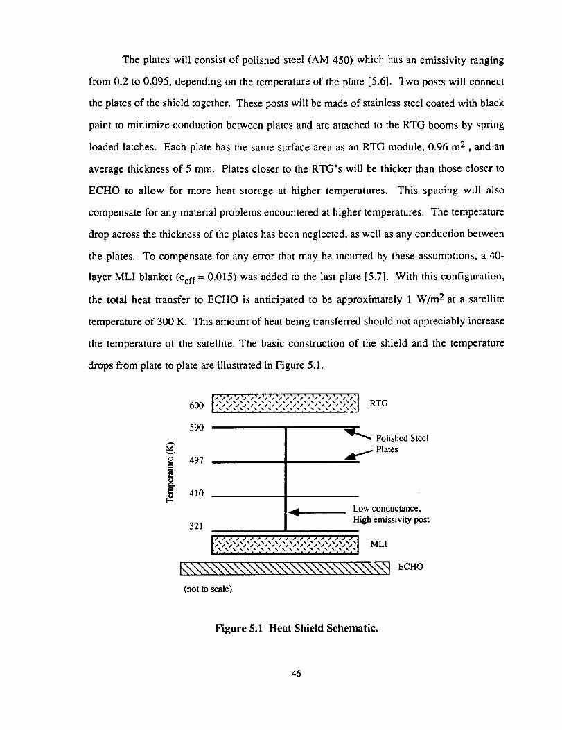
while the spacecraft is inside the fairing duringlaunch. This system will consist of a shield including
steel plates and multilayer insulation (MLI) placedbetween the RTG's and the satellite in the stowed
position in the Delta rocket. For the five minutesbetween loss of air conditioning and separation fromthe fairing, this shield will absorb and reflectapproximately 14 kW of heat radiated by the RTG's.
Propulsion
The propulsion system for Project ECHO must becapable of completing the translunar orbit, injectingthe satellite into the halo orbit, and providing forroutine stationkeeping and attitude controlmaneuvers. Based on a trade study of electric, orlow-thrust, propulsion systems, the Hughes ResearchLab 13 cm ion propulsion system (IPS) was chosenfor Project ECHO. Each of the four thrusters iscapable of delivering 17.8 mN of thrust at a peakinput power of 439 W. Three power processor units(PPU's), each requiring 500 W of input power andoperating at 88% efficiency, are used to transferpower to the thrusters. The two thruster pairs aremounted to a turntable capable of rotating 360", andin addition, each thruster is connected to two PPU'ssimultaneously through a technique termed cross-strapping. This system configuration on the spunsection allows for a single level of redundancy for thethrusters and PPU's. Xenon was selected as the
propellant to be used in conjunction with the ionthrusters. Employing a stationkeeping-free orbitabout the L 2 point will drastically reduce the amount
of propellant needed. Therefore, 70 kg of propellantwould be adequate for a 10 year mission. The xenonwill be housed in two tanks constructed of AI 5456,
each having a diameter of 0.358 m and a thickness of4.39 mm. The xenon tanks will be maintained at a
constant 7.6 MPa using a helium pressurizationsystem. Three kilograms of helium, stored at 10MPa, will be housed in another aluminum 5456 tankwith a diameter of 0.295 m and thickness of 4.74 mm.
Guidance Navigation & Control
The guidance, navigation, and control subsystemwill be a fully autonomous system incorporating dualspin stabilization and low-level thrust. A computercode was written to integrate the restricted three-bodyequations in order to determine the transfer trajectory.The integration was performed backward in timestarting at the L2 point. Velocity of the spacecraft at
the L2 point was assumed to be zero. A non-optimal,zero-thrust transfer trajectory was found (see Figure4). At the L2 point, the spacecraft will perform
another transfer trajectory to place it into astationkeeping-free orbit (see Figure 5).
V
0
"_ -5.10"*.u
2
_1,1o 5
-I.5.105
f_/ M:oo.
-4"105 -3"105 -2"105 -I*105 0 1"105 2"105
X Coordinate (km)
Figure 4 Transfer trajectory from Earth to L2 point.
4OOO0
20000- /
Y(km) 0 -
-20000-
-40000 j-40O00 -20000 0
40000
20000-
ZO-
(km)
-20000-
-40000
-40000 -20000 0
x(km)
I I I
20000 40000
1I
20000 _0000
x (krn)
4OOO0
20000-
Z
(km) 0-
-20000-
-40000
-40000 -20000 0
y (kin)
20000 40000
Figure 5 Station-keeping free halo orbit.
vi
Upon separation from the third stage of theDelta, the satellite is rotating uniformly at 45 rpm.The RTGs are then deployed which slows the craft to9.4 rpm. This slower spin rate allows the satellite tobe easily maneuvered during the transfer orbit. Oncethe craft is inserted into the halo orbit, the thrusters
are used to accelerate the spun section and theBAPTA to decelerate the despun section. Theresulting spin rates are 0.5°/hr and 35 rpm for thedespun and spun sections respectively. The spin ratefor the despun section allows the antenna to remainpointed at the Earth and the Moon. The spin rate forthe spun section along with a 1.0 m long skirtattached at the bottom stabilizes the craft againstdisturbance torques for approximately two years.
The Microcosm Autonomous Navigation System(MANS) will be used as the navigation system. Itwill have to be modified slightly for this specific orbitsince it has not been tested outside of LEO/GEO.
The MANS sensors are unique to this navigationsystem because they incorporate dual horizonscanners along with silicon light detectors in eachsensor. Two sensors are sufficient to triangulate thespacecraft's position using the Moon, Sun and Earth.
Command & Data Handling
The command and data handling subsystem ofthe communications satellite must be able to
successfully process and relay data to and from theMoon and Earth. The C&DH subsystem is also usedto distribute commands and accumulate, store, andformat data from the spacecraft and payload. In itsgeneral form, the C&DH subsystem includes acentral processor, data buses, remote interface units,and data storage units. For Project ECHO, the factorsthat determine the complexity and capability of theC&DH subsystem include communications, datastorage, and guidance and navigation requirements.
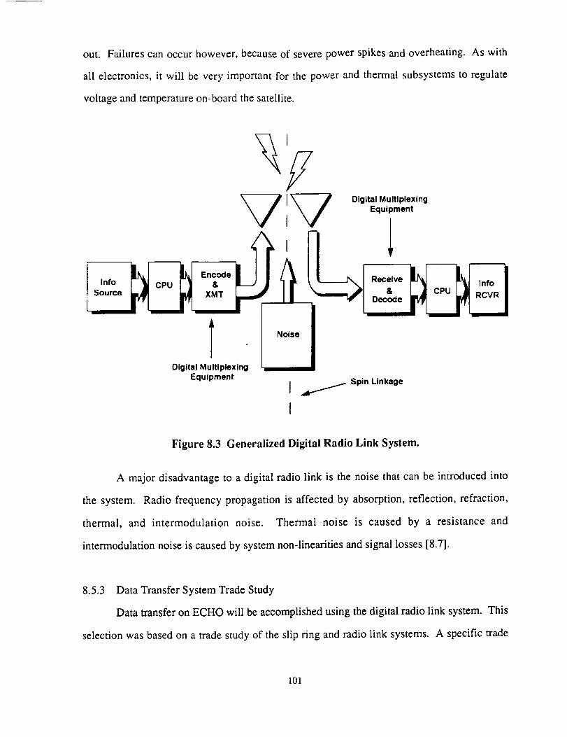
The subsystem consists of two on-board centralprocessors, one payload processor, two hardwarecontrollers, two sensor rings, two digital multiplexers,one data switch, and a digital radio link between thespun and despun platforms for data transfer. Figure 6illustrates the command architecture. The digital
radio link consists of digital multiplexing equipment,transceivers, and receivers. The components are
linked by a bus architecture and the centralprocessors to be used on-board the satellite are twoCDC 444's that will provide 3.906 Mbytes of RAMeach. The payload processor will be a HoneywellASC/PAM.
I Antenna ]
I [ PayloadCPU ]
pc 4441HardwareController ]
Thrusters I
Digital ]Radio Link [ Spin /
I , >
I Acs !l spini I ]Sensors ! [Motors [ I Ra_IgotLmlink
i [ ,l
Har wa l_1 , [C 444IController | I
I[Heaters I I
DESPUN I SPUN
Figure 6 Command architecture design.
vii
Communications
The communications subsystem of the ECHOsatellite will transmit 6 channels on the NASA Deep
Space Network (NASA DSN) using the X- and S-bands. All transmissions will be received by the34 m parabolic dish antenna provided by the NASADSN. The specified channels are one color video,two voice, one for scientific data from lunar
payloads, one satellite housekeeping and telemetry,and one for uplinked commands. Data rates for thecommunication channels are listed in Table 1.
Quadriphased Phase Shift Keying (QPSK) plus R-1/2, K=7, Viterbi soft decoding is the modulation andcoding scheme to be used for all transmissions. Thesystem will contain two dipole antennas fortransmission during the transfer orbit and a fixed,0.83 m, parabolic, dual offset feed antenna fortransmissions from the halo orbit. The system willalso contain an Frequency Division Multiple Access
(FDMA) multiplexer, two solid-state amplifiers, twodiplexers, and two transponders.
Mass, Power & Cost Budgets
The completed mass, power, and cost budgets forthis mission are as shown in Table 2. As indicated,the total estimated cost of $125.2M is $24.8M underthe $150M allowed. This total is in FY99 dollars and
will allow for unforeseen contingencies. The powerbudget total of 1280 W is under the allowable 1360W by 80 W. These power budget estimates take intoaccount losses due to wiring and the powersubsystem itself (hence the zero power requirementfor the power subsystem.) Maximum payload massof the Delta II for this mission is 1200 kg. After
setting a 20% contingency factor, the total allowablemass is 960 kg. The present design configuration ofECHO has a mass of 855.1 kg.
Table 1 Communication channel data rates.
Communications Channel
Color VideoVoice
Scientific (low)Scientific (high)
Telemetry/housekeepingUplinked commands
Data rate
44 Mbps64 kbps
75 kbps40 Mbps1000 bps1000 bps
Table 2 Mass, Power & Cost Budgets.
Subsytem
CommunicationsThermal Control
GNC
PowerStructures
PropulsionCDH
TOTAL
Mass (kg)
22.289.6
9.0321.0201.6197.014.7
Power (W)
85.0100.022.0
0.05.0
1000.058.2
855.1 1270.2
Cost (MSFY99)
13.16.1
13.960.014.04.0
14.1
125.2
viii
Conclusion
A preliminary mission design that providescontinuous communications services between the far
side of the Moon and the Earth has been completed.The design fulfills the modified Discovery-classcriteria: 1) total cost must not exceed S150 million(excluding launch vehicle), 2) launch must beachieved by a Delta-class vehicle, and 3) the designlifetime must exceed 10 years.
There are some design issues that still need to beaddressed. First, the thermal effects in the launchshroud due to the four RTG's are a major concern. Adetailed thermal analysis is required to determine ifthe heat shield will provide adequate protectionduring the time interval between loss of ground-support air conditioning and ejection of the theshroud. A reduction in the number of RTG modules
may be possible with refinements to the L2-Halo
transfer trajectory. At this time, the thrust historyrequired to inject ECHO into the halo orbit has notbee determined. If the ion thrusters do not need to
operate at full power, it would be possible to reducethe number of RTG modules. Lastly, thecommunications system for ithe data relay betweenthe Earth and the far side of the Moon is general indesign. Once the types of missions to be sent to theMoon's far side are defined, the communications
system design could become more specialized.
ix
Table of Contents
List of Figures ........................................................................................................................ xv
List of Tables ......................................................................................................................... xvi
3.3" Material Selection ........................................................................................... 12
3.3.1 Material Selection for the Skin ......................................................... 143.3.2 Material Selection for the Columns ................................................. 153.3.3 Material Selection for Fasteners ....................................................... 153.3.4 Material Selection for the RTG Booms ............................................ 163.3.5 Material Selection for the Antenna Boom ........................................ 16
3.3.6 Material Requirements for Micrometeoroid Shielding .................... 16
4.2 Power Source ................................................................................................... 29
4.2.1 Power Requirements ........................................................................ 304.2.2 RTG Design ...................................................................................... 30
4.3 Power Distribution .......................................................................................... 32
4.3.1 Power Bus-Bar ................................................................................. 324.3.2 Power Harness .................................................................................. 334.3.3 Power Control Circuits ..................................................................... 35
4.3.4 Power Auxiliary Circuits .................................................................. 37
4.4 Power Regulation ............................................................................................ 37
4.4.1 Bus Input Regulation ........................................................................ 374.4.2 Component Regulation ..................................................................... 384.4.3 Power Regulation Hardware ............................................................ 38
6.2 Propulsion System Design Overview .............................................................. 55
6.2.1 Propulsion System Determination .................................................... 556.2.2 Thruster Positioning ......................................................................... 57
xi
7.0
8.0
6.2.36.2.46.2.56.2.66.2.76.2.8
Propellant Selection .......................................................................... 59Propellant Tank Design .................................................................... 61Pressurization System ...................................................................... 63Interactive Effects of Propulsion System ......................................... 64Completion of Duties with Present Design ...................................... 69Mass, Power, and Cost Budgets ....................................................... 69
7.3.1 Spin Down ........................................................................................ 807.3.2 Disturbance Torques ........................................................................ 81
MANS System ......... . ....................................................................................... 83
7.4.1 Background ...................................................................................... 837.4.2 The MANS Sensor ........................................................................... 83
NASA DSN .................................................................................... 109
Frequency Ranges .......................................................................... 109Ground Segment and Operations Cost ........................................... 110
Trade Study Comparing CRA and DRA Systems ............................................ 33
Trade Study Comparing Electromechanical and Solid-state Relays ................ 36
Trade Study Comparing FCH and HC Electromechanical Relays ................... 36
Some Specifications for Arnold Magnetics EL-2000 SeriesPower Regulators .............................................................................................. 38
Final Subsystem Design Budget Estimates ....................................................... 39
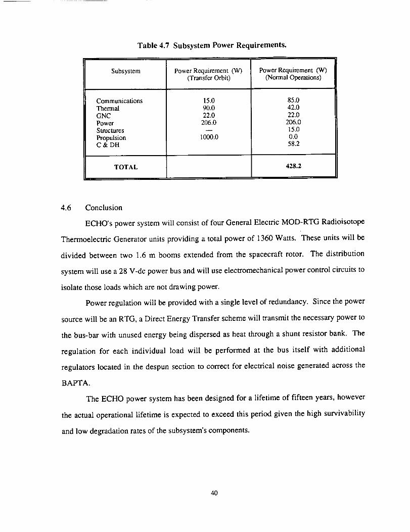
Subsystem Power Requirements .......................................... : ............................ 40
Thermal Control Trade Study ........................................................................... 47
Thermal System Budget .................................................................................... 51
Trade Study on Electrical Propulsion Systems ................................................. 56
Specification of Possible Propellants ................................................................ 59
Tank Mass and Size for Prospective Propellants .............................................. 59
Trade Study of Ion Thruster Propellants ........................................................... 60
Trade Study of Propellant Tank Materials ........................................................ 62
System Monitoring Channel Breakdown .......................................................... 66
Mass, Power, and Cost Budgets for Propulsion Subsystem ............................. 70
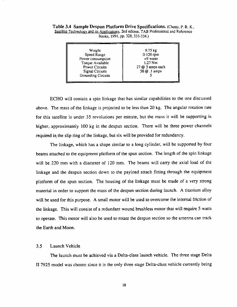
The available information is for a despunplatform that containsonly antennasand
experimentsthat needaccuratepointing. The massof this platform is most likely much
lower than the massof the despunplatform of ECHO becausethe despunplatform will
containmostof the neededcomputers.The specificationsof this platform canbe found in
Table 3.4.
17
Table 3.4 Sample Despun Platform Drive Specifications. (Chetty, P. R. K.,Satellite Technology and its Applications, 2nd edition, TAB Professional and Reference
Books, 1991, pp. 328, 333-334.)
WeightSpeed Range
Power consumptionTorque Available
Power CircuitsSignal Circuits
Grounding Circuits
9.75 kg0-120 rpm<9 watts1.27 Nm
27 @ 3 amps each58 @ .1 amps
5
ECHO will contain a spin linkage that has similar capabilities to the one discussed
above. The mass of the linkage is projected to be less than 20 kg. The angular rotation rate
for this satellite is under 35 revolutions per minute, but the mass it will be supporting is
higher, approximately 100 kg in the despun section. There will be three power channels
required in the slip ring of the linkage, but six will be provided for redundancy.
The linkage, which has a shape similar to a long cylinder, will be supported by four
beams attached to the equipment platform of the spun section. The length of the spin linkage
will be 220 mm with a diameter of 120 mm. The beams will carry the axial load of the
linkage and the despun section down to the payload attach fitting through the equipment
platform of the spun section. The housing of the linkage must be made of a very strong
material in order to support the mass of the despun section during launch. A titanium alloy
will be used for this purpose. A small motor will be used to overcome the internal friction of
the linkage. This will consist of a redundant wound brushless motor that will require 5 watts
to operate. This motor will also be used to rotate the despun section so the antenna can track
the Earth and Moon.
3.5 Launch Vehicle
The launch must be achieved via a Delta-class launch vehicle. The three stage Delta
II 7925 model was chosen since it is the only three stage Delta-class vehicle currently being
18
produced. The payload fairing and the payload attach fitting were chosen based on the mass,
volume, and trajectory specifications of the satellite as detailed in Sections 3.5.1 and 3.5.2.
The satellite should be positioned in the usable payload envelope above the separation plane
shown in Figure 3.4. Otherwise, the critical clearances would need to be analyzed.
3.5.1 Payload Fairing
The payload fairing (PLF) will shield the spacecraft from buffeting and aerodynamic
heating while in the lower atmosphere. The fairing will then be jettisoned during the second
stage of the flight at an altitude no less than 125 km. The 2.9 m diameter payload fairing will
be used because it is the only fairing size that permits the Delta 7925 to place a 1200 kg
spacecraft into a translunar trajectory. Since this fairing allows for an increased payload of
50 kg, the spacecraft's mass can be increased which will allow for any necessary
contingencies. The 2.9 m diameter fairing also has a lighter structural mass which saves
159 kg [3.7].
The separation plane is the space around the payload attach fitting, which is
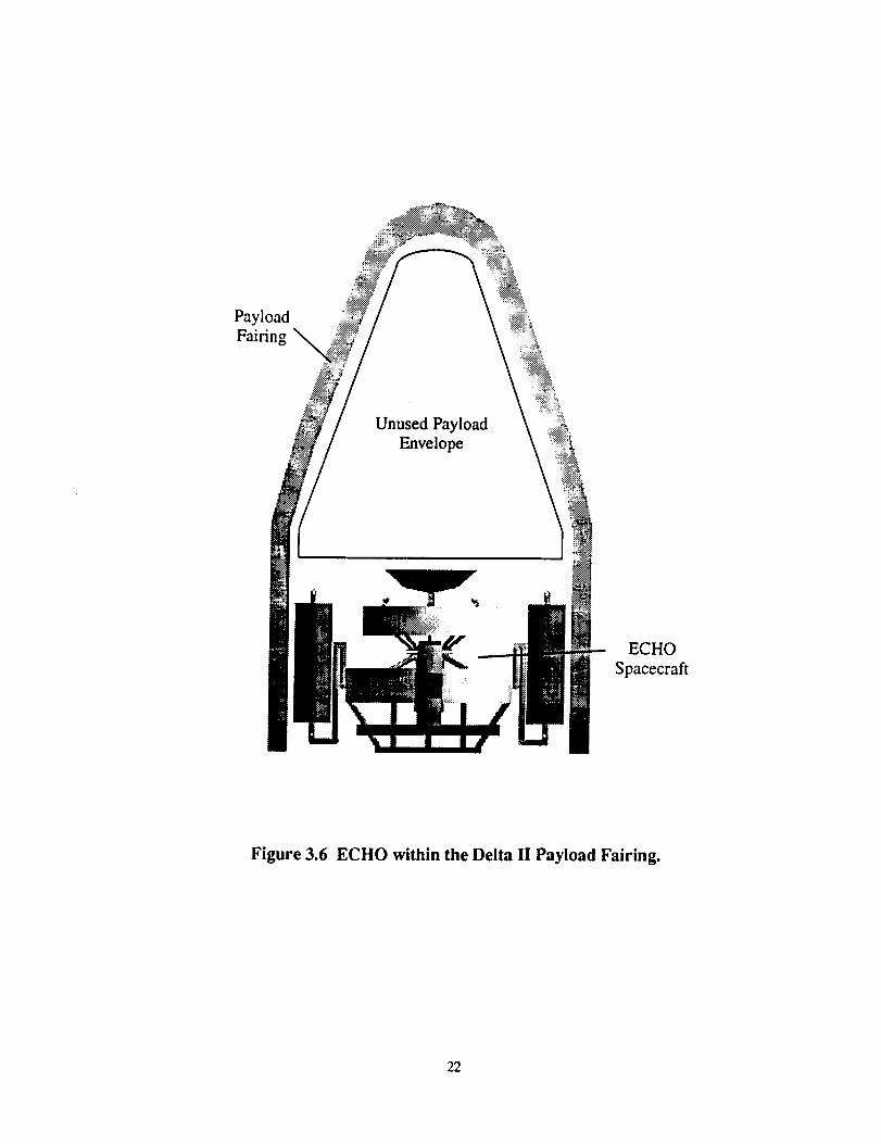
connected to the PAM-D motor. See Figure 3.4 for the PLF dimensions. The stowed
configuration of the satellite is shown in Figure 3.5. The stowed satellite and the PLF are
shown in Figure 3.6. It can be seen that the satellite will not enter any restricted areas in the
PLF.
3.5.2 Payload Attach Fittings
The payload attach fitting (PAF) is the interface between the spacecraft and the third
stage of the Delta II 7925 model. The PAF supports the clamp assembly which attaches the
spacecraft to the third stage and allows the spacecraft to be released on separation. The PAF
that is used with the three-stage Delta rocket is the 3712 model PAF. This fitting is available
in three configurations depending on the specifications of each satellite to meet the
spacecraft's mass and center of gravity requirements. The 3712C PAF was chosen for Project
19
_ Motor
PAF
_] Usable Payload Envelope
vJ/_J- Fairing Envelope
Usable Envelope BelowSeparahon Plane
mm
" Sta
20 deg
15
• Sta 333.51
2896.0 "--'--"
114.00
Projections of spacecraftappendages below thespacecraft separahon planemay be permittedbut must be coorchnatedwith the Delta Program Office
Note: 1. All Station Numbers Are =n tncnes2. Station Numbers With an Astensk (')
Indicate Outside Stations
Sta 219.22
266,2
1
R 26.60523.2
20.60
159.8
6.29
31570
Figure 3.4 Spacecraft Envelope, Star 48B Configuration with 3712 PAF.(Commercial Delta II Payload Planner's Guide, McDonnell Douglas Commercial Delta, Inc.,
Huntington Beach, California, 1990, p. 3-5.)
2O
0,,rob
=
GQ
IN
0=
21
Payload
Fairing
Unused Payload
Envelope
ECHO
Spacecraft
Figure 3.6 ECHO within the Delta II Payload Fairing.
22
ECHO because of the spacecraft's mass (1200 kg) being less than the maximum limit of
model C at 1361 kg [3.8]. The flange requirements and PAF configurations are shown in
Figures 3.7 and 3.8. From the dimensions in these diagrams, the satellite interface conforms
to these specifications in order to attach the spacecraft to the PAF. As the configuration of
the satellite was determined, the fittings and clamps were designed to meet these
specifications.
3.6 Budgets
3.6.1 Cost Budget
The launch vehicle and structures design group was allotted $15 million for the cost
budget. The cost of the launch vehicle is not included in this project's budget. The
distribution of the $15 million is shown in Table 3.5.
Table 3.5 Structures/Launch Vehicle Cost Budget.
Item
AluminumTitanium
Manufacturing and Testing20 % Contingency
TOTAL
Cost (millions of dollars, FY99)
0.20.310.53.0
14.0
The cost of purchasing the material is very small compared to the manufacturing and
testing of the structure. These values include manufacturing three identical satellites. One
satellite will be used for failure testing, another for non-destructive evaluation, and the third
will be launched into orbit.
23
For Section MarkeO _ iArea = 269 mm2/0,417 in.2 + 15% I
I = 11,654 mm4/0,028in. 4 +. 15% IApplicable Length. L 25.4 mini1.0 in. I
[3.2] Metals Referen¢_ Book, American Society for Metals, 1981.
[3.3] Metals Handbook, American Society for Metals, 9th ed. Vol. 2, 1990
[3.4] Strong, Dr. A. Brent, Fundamentals of Composites Manufacturina, Society ofManufacturing Engineers, Dearborn, Michigan, 1st ed., 1989, pp. _222-223.
[3.51 Stella, Paul M., LEO Micrometeorite/Debris Impact Damage, California Institute of
Technology, 1991.
[3.6] Chetty, P. R. K., Satellite Technology and its Applications, 2nd. edition, TABProfessional and Reference Books, 1991, pp. 328, 333-334.
[3.7] Isakowitz, Steven J., International Reference Guide to Space Launch Systems,American Institute of Aeronautics and Astronautics, Washington D.C., 1991, p. 205.
[3.8] Commercial Delta II Payload Planner's Guide, McDonnell Commercial Delta, Inc.,Huntington Beach, CA, 1990, p. 5-2.
[3.9] Commercial Delta II Payload Planner's Guide, p. 3-5.
[3.10] Commercial D¢lta II Payload Planner's Guide, p. 5-11
[3.11] Commercial Delta II Payload Planner's Guide, P. 5-5
28
4.0 Power Subsystem
4.1 Introduction
This section details the design of the electrical power subsystem (EPS) for Project
ECHO. Several parameters guided the design of the EPS. Project ECHO is a modified
NASA Discovery-class mission subject to the following criteria: 1) the total mission cost
must not exceed $150 million, 2) launch must be achieved by a Delta class launch vehicle,
and 3) the operational lifetime of the spacecraft must be ten to fifteen years, subject to the
first two requirements. The propulsion system will utilize ion thrusters which will require a
large amount of power in relation to the other satellite components as a whole. The peak
power for ECHO is 1180 W. However, since the thrusters will use a reduced amount of
power after achieving the L2 orbit, the period of maximum power consumption will be
during the transfer orbit and will require 1095 W.
Several topics are covered: methods of power generation are discussed, along with
the current architectures of the power distribution and regulation schemes. Rationale is given
for all decisions and the overall system design is summarized.
4.2 Power Source
Two types of main power sources have been considered for ECHO, photovoltaic and
radioisotope thermoelectric generators (RTG). Initially, the photovoltaic system was to be
used in order to minimize overall system cost. However, the solar arrays needed to generate
the power for the spacecraft tended to shadow the communications subsystem antenna. In
light of this fact, the project integration team, in conjunction with the power subsystem team
has decided on the use of an RTG system.
29
4.2.1 PowerRequirements
The power sourcewill needto provide enough power to operateall functioning
subsystemsat any given time during the mission. The period of maximum power
Based on this relationship, the system with the greatest value for the performance index
would be the best choice for the specific mission requirements. A trade study shown in Table
6.1 compares four types of electric propulsion systems: ion propulsion (electrostatic), arcjets
(electrothermal), resistojets, and magnetoplasmadynamic propulsion. A trade value of one
through four was assessed to each system in five different categories. A value of one was
considered the lowest, or worst, value and four was considered the highest, or best, value for
each respective category.
Table 6.1 Trade Study on Electrical Propulsion Systems.
System
Ion PropulsionArcjet Propulsion
ResistojetMagnetoplasmadynamic
Performance Risk SystemMass
4 1 44 2 14 3 24 4 3
PropellantMass
Power
Required
3333
-0.35-0.55-1.15-1.35
The above table indicates that the ion propulsion system (IPS) is the best possible choice for
ECHO based on the mission specifications. The thruster chosen for ECHO is the Hughes
Research Laboratories 13 cm ion thruster. This decision was based on the thruster's space
proven reliability, long life expectancy, and a thrust output in the range appropriate for
ECHO. Each thruster is capable of providing 17.8 mN of thrust at a peak input power of
56
439 W [6.1]. The Isp of the thruster is 2585 sec, and the overall thruster efficiency is 51%
[6.21.
To provide the power to each thruster, three power processor units (PPU) will be
used. Each PPU will receive power directly from the power bus and from there transfer it to
a thruster. The PPU's require an input power of 500 W and have an operational efficiency of
88% [6.3].
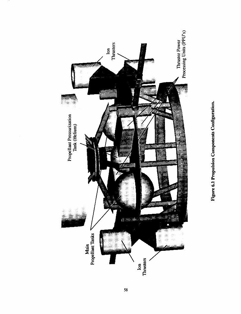
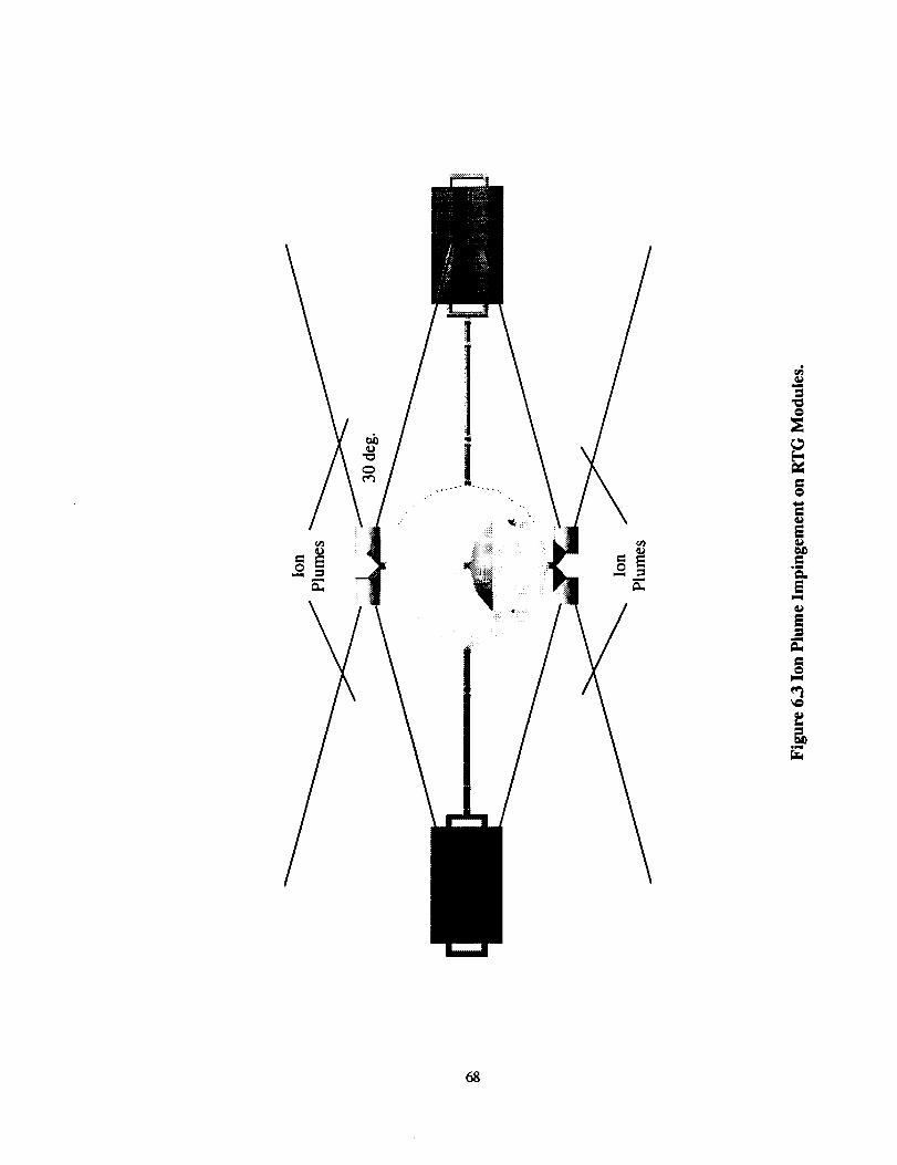
6.2.2 Thruster Positioning
Any thruster positioning scheme should provide for movement of the satellite along
all three principal axes as well as provide some level of redundancy to the system as a whole.
Figure 6.1 displays the thruster configuration to be used for ECHO. This scheme not only
provides degrees of freedom along all three principal axes, but also allows for some level of
redundancy for the propulsion system. To further explain, there are two pairs of thrusters
located on the side of the spun section. These thrusters are mounted on a titanium plate (or
turntable) that is in turn connected to a stepper motor. This allows the thrusters to be rotated
360 ° in a plane parallel to the spacecraft longitudinal axis. The Hughes Research Laboratory
thrusters are also capable of being gimbaled 90 ° in the plane perpendicular to the spacecraft
longitudinal axis. This combination allows for motion of the satellite in all three principal
directions. Because the thrusters can be gimbaled 90 ° , as well as rotated 360 ° , each thruster
can fire in the same directions, which will provide a single level of redundancy.
The PPU's are also placed in the spun section. The PPU is used to step up the voltage
received from the power bus, to the amount that required by various components within the
thruster. Each thruster will be directly wired to two of the PPU's by means of cross-
strapping. This arrangement allows for a single level of redundancy in the event that one of
the power processor units experiences difficulties.
57
o_
58
6.2.3 Propellant Selection
For an electric ion thruster, the optimum propellant must have a high ion mass, high
specific charge, high ionization potential and a manageable storage size and temperature.
However, only certain propellants can be used with an ion thruster: argon, cesium, helium,
hydrogen, hydrazine, krypton, mercury, and xenon. Cesium was immediately discarded
because of the corrosive nature of the gas. Hydrazine, helium, and mercury were also
eliminated from consideration because they are corrosive materials with cryogenic storage
temperatures that would be too difficult to maintain.
The molecular properties of the three remaining gases are given in Table 6.2, with the
relative masses and sizes of the corresponding propellant tanks given in Table 6.3.
Table 6.2 Specification of Possible Propellants. (Hill, Philip G., and Carl R.Peterson, Mechanics and Thermodynamics of Propulsion, Addison-Wesley Publishing
Company, New York, NY, 1992, p. 659).
Propellant
Argon
KryptonXenon
Mass
(10E-25 kg)
0.661.39
2.18
q/m(10E5 Clkg)
24.13
11.50
7.34
I st Ionization
Potential (eV)
15.80
14.00
12.13
Table 6.3 Tank Mass and Size for Prospective Propellants. (Rawlin, V.K,
M.J. Pauerson, and R.P. Gruber, "Xenon Ion Propellant for Orbit Transfer," AIAA-90-2527,
NASA Lewis Research Center, p. 22.)
Propellant
Argon
KryptonXenon
Tank Mass Fraction
0.75
0.27
0.14
Tank Radius (m)
for 1041 kg
0.49
0.62
0.82
59
Using this information, and the performance index,
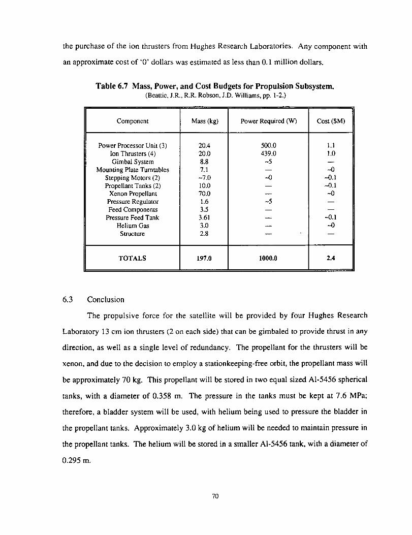
The propulsive force for the satellite will be provided by four Hughes Research
Laboratory 13 cm ion thrusters (2 on each side) that can be gimbaled to provide thrust in any
direction, as well as a single level of redundancy. The propellant for the thrusters will be
xenon, and due to the decision to employ a stationkeeping-free orbit, the propellant mass will
be approximately 70 kg. This propellant will be stored in two equal sized A1-5456 spherical
tanks, with a diameter of 0.358 m. The pressure in the tanks must be kept at 7.6 MPa;
therefore, a bladder system will be used, with helium being used to pressure the bladder in
the propellant tanks. Approximately 3.0 kg of helium will be needed to maintain pressure in
the propellant tanks. The helium will be stored in a smaller AI-5456 tank, with a diameter of
0.295 m.
7O
The costs were broken down into three areas, the main propulsion system, the
propellant system, and the miscellaneous components, with all costs being given in 1999
dollars. The cost of the main propulsion system, made up of the four thrusters, three PPU's,
a pressure regulator, feed components, gimbal components, and mounting structure was
found to be $2.1 million. The propellant system, consisting of the xenon propellant, the
helium and pressurization system, and the three tanks totaled $0.2 million. Finally, a total of
$0.1 million was allotted for the two space-rated stepping motors and turntable system. The
total cost for the propulsion subsystem will be $2.4 million and the total mass will be 197 kg,
with a power consumption of 1000 W at peak operation.
6.4 References
[6.11
[6.2]
[6.3]
[6.4]
[6.5]
[6.6]
[6.7]
[6.8]
[6.91
Beattie, J.R., R.R. Robson, and J.D. Williams, "18-mN Xenon Ion PropulsionSubsystem," IEPC-91-010, October 14-17, 1991, Viareggio, Italy, p. 1.
Beattie, J.R., R.R. Robson, and J.D. Williams, p. 2.
Beattie, J.R., R.R. Robson, and J.D. Williams, p. 4.
Hill, Philip G., and Carl R. Peterson, Mechanics and Thermodynamics ofPropulsion, Addison-Wesley Publishing Company, New York] NY, 1992, p. 659.
Rawlin, V.K, and M.J. Patterson, and R.P. Gruber, "Xenon Ion Propellant forOrbit Transfer," AIAA-90-2527, NASA Lewis Research Center, p. 22.
Farquhar, Robert, "A Halo Orbit Lunar Station," Astronautics and Aeronautics, June1972, p. 59.
Fearn, D.G., "Ion Propulsion - A Technology for Improving the Cost-effectiveness ofLarge Communication Satellites," Electronics and Communication EngineeringJou_al, June 1992, p. 154.
Donaldson, Bruce K., Analysis of Aircraft Structures. McGraw-Hill, Inc., NewYork, NY, 1993, p. 115.
Donaldson, Bruce K., p. 115.
71
[6.101
[6.111
Reid,RobertC., andJohnM. Prausnitz,andBruceE.Poling,Thq Prgperties ofGases and Liquids, 4th Edition, McGraw-Hill, New York, 1987, pp. 73-76.
Personal correspondence with Dr. Kathleen Howell, Purdue University, February 22,1994.
72
7.0 Guidance, Navigation, and Control Subsystem
7.1 Introduction
The Guidance, Navigation, and Control (GNC) subsystem will be responsible for the
trajectory, stabilization, and attitude determination and control of the spacecraft. Each of
these areas is constrained under specific criteria defined by the mission requirements. The
trajectory is limited to using low-thrust to reach the halo orbit, and the stabilization of the
satellite must be achieved via dual spin. Finally, the spacecraft must maintain semi-
autonomous attitude control. To satisfy this last requirement, the Microcosm Autonomous
Navigation System (MANS) was chosen.
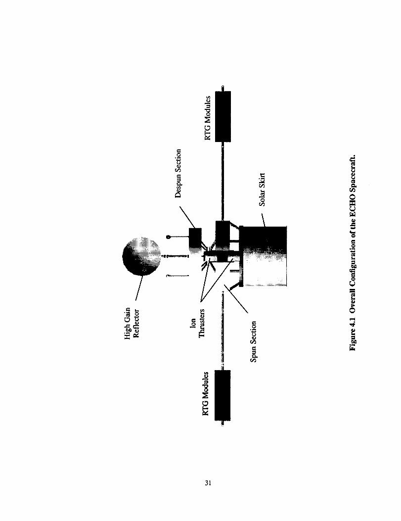
Figure 7.1 shows the current spacecraft configuration which was used in performing
all calculations. The radioisotope thermoelectric generators (RTG's) will be deployed on
booms from the sides of the spacecraft. There are two RTG modules on each side of the
satellite totaling 84 kg per boom. Since most of the mass of the spacecraft will be placed in
the spun section to increase stability, 200 kg of mass has been approximated as being in the
despun section, and 570 kg of mass has been estimated to be in the spun section. The mass
distribution in each section was modeled as being homogeneous.
7.2 Trajectory and Halo Orbit
7.2.1 Trajectory
The satellite will use a low-thrust transfer trajectory to reach the halo orbit. A
computer program (see Appendix A. 1) was written to determine the transfer. In order to
simply the trajectory problem, it was broken into two pieces: 1) low-thrust transfer from
near-Earth to vicinity of the L2 point and 2) low-thrust transfer from L2 point to the halo
orbit. Once each piece of the trajectory was found, they then could be patched together. For
73
Ct_
rS_
I-q
74
each portion of the trajectory the computer program integrates the set of restricted three-body
equations
25,- x = (s- u)(x - u)[(X_ #)2 + y2 +z2] 1"5
_,ms/c ) 4_2 + 5,2 + _2
(s-#)y
t,m,,<) 2+5,2+
_= (1-#)z
#(x+l-#)
(x + 1- #)2 + y2 + 22] 15
#Y
(x + 1 - #)2 + y2 + z2] 1-5
#Z
[(x - #)2 + y2 + z2] 1"5
Cms/c ) d$¢2 + 5,2 + _2
(x + 1 - #)2 + y2 + z2] 1-_
(7.1)
where the x-y coordinate system is attached at the center of mass of the Earth-Moon system
with x pointing in the direction of Earth; y is perpendicular to the Earth-Moon line; and z is
perpendicular to the plane in which the Earth and Moon lie and # is the ratio of Earth to
Moon mass. The last expression in each of the equations defines the addition of thrust from
the satellite tangential to the trajectory.
For the near-Earth to L2 leg of the trajectory, the motion of the satellite was assumed
to occur only in the x-y plane, therefore, z = 2 = _"= 0. Since the initial conditions for the
equations were unknown and the final conditions were known at the L2 point, the equations
were integrated backward in time from the L2 point to a near-Earth point. The integration
scheme used was a Runge-Kutta 5,6 method. Presented in Figure 7.2 is the resulting
trajectory for the first leg with the diamond symbols representing 10 day intervals along the
trajectory for time reference. There is no thrust required by the satellite during this
75
•I(, .X- *
I IiiI
I
(u_) _l_u!pzoo 3 1
_===¢
@t",,I
0
0
.g-b
el.
!
76
trajectory. The orbital energy of the transfer is shown in Figure 7.3. A Delta 7925 launch
vehicle is capable of achieving an orbital energy relative to the Earth of - 1.0 km2/sec 2 for a
1200 kg payload. So the spacecraft may be injected into the transfer trajectory between the
-30 and -40 day interval shown in Figure 7.2. The orbital energy of the satellite will
gradually increase as it moves further away from the Earth, and the actual orbital energy will
not possess sharp 'spikes'. (These spikes are the result of the approximate integration
scheme used to solve the equations of motion.)
To compute the trajectory for the second portion of the transfer, the third equation of
Equation (7.1) must now be included. It is well-known that the motion of a spacecraft near
any of the collinear equilibrium points is quite sensitive to initial conditions. Knowing the
injection position and velocity required for the halo orbit, a transfer path was sought by
integrating backwards in time from the halo injection to the L2 point. This scheme used the
"velocity-to-be-gained" method described in Reference 7.1, with the assumption of a linearly
increasing velocity from L2 (zero velocity) to the injection point. Because of the sensitivity
to small perturbations (in this case the thrust), a transfer that matched both end-points was
not found; however, families of transfers between neighborhoods of the desired end-points
give confidence that an exact transfer (requiring approximately 14 days) should be possible.
Determining that exact transfer would require the use of an optimal control approach.
7.2.2 Halo Orbit
Various halo orbits can exist around Lagrange equilibrium points, but for the
purposes of this mission, two specific halo orbits were considered - a circular halo orbit with
a radius of 3500 km and a stationkeeping-free orbit was considered. Originally, the circular
orbit had been proposed because it allowed for constant communication between the Earth
and Moon [7.2]. However, the orbit is not stable and would require a AV of 400 ft/s/yr for
stationkeeping. This translated into a constant thrust of approximately 7.0 mN using the ion
........................ _..... i--,..,o=_-:, , ! ='_i o i
,' ,' i__-_:: : ,_o:
, , _i o
i i
I o
i i
i i
I I I
0
o . .
i
i
I I
(zSlzm_ q;zu_ _'z',_, _z_u_ l_!qao
0
0
!
a
=
m
Iml
0
I
78
thrusters. Since the lifetime of each thruster is on the order of 10000 hours, the circular orbit
could not be maintained during the 10 year lifetime.
Recently, a new halo orbit was proposed that would require no stationkeeping [7.3,
7.4], but it is also highly elongated in the y-direction. Figure 7.4 shows three different views
of this halo orbit. The semiminor axis of the orbit is 3500 km long, and the semimajor axis
40000
20000-
Y 0-(k_m)
-20000-
-40000
iI
-40000 -20000I I0 20000 40000
x (kin)
40000 40000
20000-
z
(kin) O-
-20000-
-40000 _ i I-40000 -20000 0 20000 40000
x(km)
20000-
z0-
(kin)
-20000-
-40000 I-40000 -20000
I I
0 20000 40000
y (kin)
Figure 7,4 Stationkeeping-free Halo Orbit. (Howell, K.C. and Bell, J., PrivateCommunication with R.G. Melton, February 22, 1994)
79
G-2---
length equals 35000 km. ECHO will use this halo orbit for its mission to conserve propellant
and reduce complexity.
7.3 Spacecraft Stabilization
7.3.1 Spin down
The spin down of the satellite will occur shortly after the third stage is deployed from
the Delta launch vehicle. Figure 7.1 shows the satellite configuration that was used to
calculate the mass moments of inertia. Sample calculations for the moments of inertia,
angular momentum, and spin rates can be found in Appendix A.3. The spin rate of the
satellite when deployed from the third stage will be approximately 45 rpm. For the duration
of the mission, the despun section will have to rotate approximately once every 28 days to
keep the antenna dish facing the Moon at all times, and the spun section will rotate at
approximately 37 rpm to provide stability against disturbance torques. The RTG's will have
to be deployed as soon as possible to reduce the amount of heat being transferred to the
satellite, which will slow its spin rate. After the satellite reaches the halo orbit, it will then
reconfigure itself into the dual spin mode using the BAPTA (Bearing and Power Transfer
Assembly) to spin down the despun section and the thrusters to spin-up the spun section. The
spin rates for each part of the mission can be found in Table 7.1.
Table 7.1 Spin Rates.
Before RTG deploymentAfter RTG deployment
(before Halo orbit)Before final spin-up
Final spin rates
Despun Section
45 rpm8.6 rpm
24.8* 10"6rpm
24.8* 10-6 rpm
Spun Section
45 rpm8.6 rpm
8.76 rpm
37 rpm
80
7.3.2 Disturbance Torques
Magnetic, gravity gradient, and solar pressure torques all affect a spacecraft's
stability. However, the Moon has no significant magnetic field, and the halo orbit is far
enough away from the Earth's magnetic field that it too has a negligible effect. Therefore, the
only torques acting on the spacecraft are from the gravity gradient and the solar pressure.
The gravity gradient torque is calculated using:
Tg ------_---a-3]AM°°n I -/,Isin(20) (7.1)
where
R =0 =
/a =h =
the Moon's gravitational parameterthe distance from the Moon to the spacecraftthe maximum allowable nutation anglethe axial moment of inertiathe transverse moment of inertia
The result for ECHO is a gravity gradient torque of 1.4x10 -9 Nm.
The solar pressure force is calculated using Equation 7.2.
PATs=--
C
(7.2)
where: e
C --
A =
the power fluxthe speed of lightthe surface area exposed to the sun aboveor below the center of mass
Once the solar pressure force is known, Equation 7.3 can be used to obtain the actual torque
due to the solar pressure:
M s = Tsd (7.3)
81
where d is the perpendicular distance from the centroid of the exposed area to the center of
mass. The total solar pressure torque is the difference between the torques acting above and
below the center of mass.
The spin rate necessary for the despun section to maintain a "fixed" pointing relative
to the Earth and Moon can be found by dividing the orbit of the Moon by its period and is
equal to 0.5°/hr. Calculating the spin rate for the spun section involves the equation:
Mdto9 = _ (7.4)
lstanO
where: M
dt =
Is =0 =
the torque that needs to be stabilizedthe time over which the torque is applied
the spin moment of inertiathe maximum nutation angle
Substituting the torques into Equation 7.4 yields an extremely high spin rate which is largely
due to the solar torque since the antenna projects a greater area above the center of mass than
the spun section projects below. Therefore, some method of reducing the solar torque is
required.
In order to reduce the solar torque, a one meter long skirt will be extended down from
the top of the tapered section of the spacecraft. The skirt would lower the total torque that
needs to be stabilized against. However, the projected area of the front of the antenna is
greater than that for the side. This results in different solar pressure torques acting on the
satellite as the despun section rotates. To optimize the skirt area for minimum average
disturbance torque, Equations 7.2 and 7.3 were used in an iterative process until the solar
torque acting on the front was equal and opposite to the torque acting on the side. Equation
7.4 was then implemented to obtain the spin rate necessary to stabilize the spacecraft against
the solar torque. The results of this iteration are tabulated in Appendix A.4.
Even though solar activity causes fluctuations in the solar power flux, the above
process assumes that the solar torque remains constant. To maintain the pointing accuracy of
82
1°for two years,a spin rateof 37 rpm will be requiredwhich is high enoughto allow for a
marginof error in thecalculations. Stationkeepingwill thenbeneededapproximatelyevery
two yearsto countertheeffectsof solartorque.
7.4 MANS System
7.4.1 Background
The MicrocosmAutonomousNavigationSystem(MANS) providesa spacecraftwith
low-cost, fully autonomousnavigation and attitude determination. MANS provides the
position andvelocity of the spacecraftevery 250 milliseconds,andit canalso provide the
position vector of the Sun in spacecraftcoordinatesand the groundlookpoint [7.5]. The
systemusesone or moresensorsto observethe Earth, Sun,and Moon [7.6], andposition
accuraciesareexpectedto rangefrom 100metersto 3 kilometers [7.7]. MANS processes
sensordata through sophisticatedsoftwareconsistingof over 35000 lines of Ada code.
However,MANS doesnot possessanyspecificmass,power,or sizerequirementsother than
thosenecessaryfor the sensors[7.8]. The MANS systemwas first flight testedin 1993,but
no informationfollowing thattesthasbeenmadeavailableyet [7.9].
7.4.2 TheMANS Sensor
The MANS systemhasprimarily beenconfigured to receive data from the main
sensor, a modified Dual Cone Scanner(DCS). The DCS is a product of the Barnes
EngineeringDivision of EDO Corporationin Shelton,Connecticutand usesa motor driven
optical scanningheadthatis capableof detectingtheEarth'sthermalradiancealongwith the
SunandMoon's visible light. To provideaccurateandcontinuousdata,the DCSspinsat a
70° field of view. In additionto theDCS,theMANS employstwo fan sensorsthatdetectthe
SunandMoon andoperatewith 180degreefields of view. TheMANS sensorhasa massof
83
4.5 kg and requires 11 Watts of power [7.10]. The actual dimensions of the cylindrical
sensor have not been found, but they have been approximated to be 0.2 meters long and 0.08
meters in diameter.
Although the sensor has not been tested for use in the halo orbit, the assumption is
that it will still be effective there. Two sensors will be used in an effort to increase the
accuracy of the navigation system, and they will be placed 180 degrees apart on the outside
of the despun section of the satellite. This placement will provide data from at least one
sensor at all times. The despun section was chosen because the DCS is primarily used for
three-axis stabilized spacecraft [7.11] and because it also reduces the complexity of the
processing software.
7.5 Budget
Table 7.2 shows the budget breakdowns for the GNC subsystem.
Table 7.2 GNC Budgets.
[ Mass (kg) 9.0
Power (W) 22.0Cost (M$,FY99) 14.7
The MANS sensors are the only variables in the power and mass budgets. Actual cost values
were not found so the cost was approximated using a cost estimation program [7.12]. The
cost value is given in terms of 1999 dollars. However, the estimation program tends to
overestimate the cost, and therefore, the value given above may be higher than the actual
cost.
84
7.6 Conclusion
The low-thrust trajectory for the transfer orbit was found by the course instructors
using a computer code. The satellite will take approximately 70 days to reach the L2 point.
Once at the L2 point, the spacecraft will be placed into a stationkeeping-free orbit, but the
details of how the satellite will be placed into the halo orbit have not been determined.
When the RTG's are deployed immediately after the satellite leaves the third stage of
the Delta launch vehicle, the spin rate of the spacecraft will be decreased from 45 rpm to
8.6 rpm, and once the satellite reaches the halo orbit, the BAPTA will slow the spin rate of
the despun section to one revolution per 28 days while thrusters will be used to increase the
spin rate of the spun section to approximately 37 rpm.
There are two disturbance torques significant enough to be dealt with during the
mission lifetime. The solar torque has a magnitude of 10 -6 and will be more significant than
the gravity gradient torque which has a magnitude of 10 "9. While the spin rate of the satellite
will create more than enough stability to compensate for the gravity gradient torque, the solar
torque caused by the parabolic antenna must also be counteracted by the use of a 1.0 m long
skirt extending from the top of the tapered section of the spacecraft.
The MANS system has been chosen as the best navigation system for ECHO. The
decision to use MANS in the halo orbit is based on the assumption that the software and Dual
Cone Sensors can be modified for use in the halo orbit. Two sensors will be used for the
MANS system to increase accuracy and reliability of the system and will be placed 180 °
apart on the despun platform of the satellite.
7.7 References
[7.1]
[7.2]
Battin, Richard H., An Introduction to the Mathematics and Methods ofAstrodynamics, American Institute of Aeronautics and Astronautics, Inc., New York,NY, 1987.
Farquhar, R. W., "A Halo-Orbit Lunar Station," Astronautics and Aeronautics, June1972, pp. 59-63.
85
[7.3] Howell, K.C. andH. J.Pernicka,"Sun-EarthLibration PointTrajectoriesthatAvoidthe SolarExclusionZone,"The Journal of the Astronautical Sciences, Vol. 38, No. 3,July/September 1990, pp. 269-288.
[7.4] Howell, K.C., Private communication with R. G. Melton, Feb. 22, 1994.
[7.5] Wertz, James R. and E. David Skulsky, "Fully Autonomous Navigation for theNASA Cargo Transfer Vehicle," NASA Document #N93-22318. Abstract only.
[7.6] Wertz, J.R. and W.J. Larson, eds., Space Mission Analysis and Design,Microcosm, Inc., Kluwer Academic Publishers, 1992, pp. 473,475.
[7.7] Tai, Frank and Peter D. Noerdlinger, "A Low Cost Autonomous NavigationSystem," Paper No. AAS 89-001 presented at the 12th Annual AAS Guidance andControl Conference, Keystone, Colorado, Feb. 4-8 1989.
[7.8] Wertz and Larson, p. 484.
[7.9] Wertz and Larson, pp. 473,475.
[7.101 Anthony, Jack, "Autonomous Space Navigation Experiment," Paper No. AIAA 92-1710 presented at the AIAA Space Programs and Technologies Conference.Huntsville, Alabama, March 24-26 1992.
[7.11] Tai, p. 4.
[7.12] Cyr, Kelley, "Cost Estimation Methods for Advance Space Systems," NASAJohnson Space Center, 1988.
86
8.0 Command and Data Handling Subsystem
8.1 Introduction
The command and data handling (C&DH) subsystem for ECHO must collect,
process, and redistribute commands and data for the satellite. These commands and data may
originate from several sources such as the lunar surface, a command station on Earth or other
subsystems aboard the spacecraft. Essentially, the command and data handling subsystem is
the brain of the satellite, serving to make decisions regarding data routing and organization.
As a preliminary requirement, it was decided to design a semi-autonomous C&DH
subsystem. This would minimize ground interaction and maintenance because the satellite
will be capable of monitoring its health and status while adjusting for any variation from a
pre-planned guideline. Telemetry and ground communication will still be possible, allowing
periodic checks and adjustments to be made if necessary.
Reliability is also a major concern; an inoperative satellite is of very little use.
Therefore, redundant processing units and data paths must be designed into the C&DH
subsystem to minimize the chances of failure. The central processors will have the capability
of accommodating the various throughput levels of the communications and GNC
subsystems with which it will communicate. In addition, should a failure occur, the
remaining hardware must be capable of sustaining satellite functions at least at some
minimum level.
Finally, mass and volume of this subsystem must be minimized. As launch cost is
directly proportional to mass, a mass reduction will save money as well as reserve more room
for propellant storage which will increase the expected mission lifetime.
What follows is a command and data handling subsystem design for ECHO. The
discussion includes a detailed description of the system architecture, processors, software,
and the data transfer system. An overview of the mass, power, and cost budgets is also
included.
87
8.2 Architecture
The commandand datahandlingsubsystem'sarchitectureis driven by the satellite's
dual-spin configuration. Due to the needof relaying dataacrossthe spin linkage, a bus
architecturewasdeemedthemost logical asthebackboneof the system.This providesthe
mosteffective methodof communicationbetweenthe spunanddespunsections. The bus
• Input/Output Handlers• BIT and Diagnostics(b) Subtotal: COTS(c) Subtotal: Non-COTS(d) Operating System Subtotal(e) Total Software Size and
Throughput EstimateMar_in Calculations:
(to Needed to compensate for
Estimation
Source
Frequency(Hz)
10.0010.0010.00
5.00
5.001.000.10
41.10
m=720 (1)
(b)+ (c)
_a) + (d)
100% ofnon-COTS:
Required Memory
Code
(K words)
1.01.0
15.04.02.01.20.8
25.0
10.00.70.0
10.710.7
35.7
35.7
Data
(K words)
4.02.5
10.01.0
10.00.51.5
29.5
RequiredThroughput
(KIPS)
7.03.0
20.015.05.05.03.0
58.0
3.5 36.00.4 0.50.0 N/A3.9 36.53.9 36.5
33.4 94.5
94.5
requirements uncertainty
(g) On-orbit spare
Estimate of computerrequirements
1.0*[(a) + (c)]
100% spare:1.0"[(e)+ (f)]
(e) + (tO + (g)
71.4
142.8
33.4
66.8 189.0
378.0133.6
(I)
COTS -- commercial-off-the-shelf
m = number of data words handled per second.m = 29.5 K words/41.10 Hz = 717.76 words/see ~ 720 words/see
8.3.3 Comparison
The software requirements contain three important drivers: required memory,
required throughput, and SLOC to be written. These values are compared in Table 8.3.
Although the MANS system requires a greater throughput, it should be easier to implement.
To eliminate the possibility of an error in computations, the larger values will be used for
hardware sizing. This is because the MANS system and the customized system should have
approximately the same software.
92
Table 8.3 MANS versus Customized System.
Function
SLOC to be writtenRequired Memory (Mbytes)Required Throughput (KIPS)
MANS
6,2930.431,378
Customized
13,3860.64
1,302.8
8.3.4 Payload Software
Since the throughput for the communication system is expected to be very high, all
communications will be sorted with a separate processor. ECHO will receive 7-byte packets
at 90 Mbytes/second. This data will arrive at the payload processor where it will be checked
for errors by convolutional coding. This code is designed to be run in the background and
therefore is very fast and efficient. If the data is error free, the payload processor will then
determine its destination. There are three possible destinations: the Moon, the Earth, or one
of the satellite's processors. If the data has an error the code will correct it if possible, request
retransmission, or if necessary, ignore it. The software requirements for the payload
processor are shown in Table 8.4. Here, the number of data words handled per second, m,
has twice the transmission rate, 90 Mbytes/second, added to it. The payload processor will
require 0.183 Mbytes of memory, a throughput of 344 KIPS, and a total of 3,756 SLOC in
Ada.
8.4 Hardware Selection
With the selection and sizing of the software complete, a decision on system
hardware, mainly the CPU's, can be made. Although MANS will most likely be used, the
larger software estimate will be used to size the hardware. This is because the MANS system
must incorporate all the software in the non-MANS estimate.
93
Table 8.4 Payload Software Requirements. (Wertz, James R., and Wiley, J.
Larson, Space Mission Analysis and Design, Microcosm, 1992, p. 627)
Component
Aoolication Functions: [8.3]
• Fault Monitors• Fault Correction
(a) Application SubtotalQI_: [8.4]• Local Executive
• Runtime Kernel (COTS)• Input/Output Handlers• Bit/Diagnostics• Math Utilities
(b) Subtotal: COTS(c) Subtotal: Non-COTS(d) Operating System Subtotal
(e) Total Software Size andThroughput EstimateMar¢in Calculations:
(f) Needed.to compensate for
Estimation
Source
Frequency(nz)5.005.00
10.00
n=30 (1)m=l130 (2)
(b) + (c)
Required Memory
Code
(K words)
4.02.06.0
3.58.0
10.00.71.28.0
15.4
Data
(K words)
1.010.011.0
RequiredThroughput
(KIPS)
15.05.0
20.0
(a) + (d)
100% of non-COTS:
23.4
29.4
21.4
2.0 9.04.0 N/A3.5 56.50.4 0.5
0.2 N/A4.0 N/A6.1 66.0
10.1
21.1
66.0
86.0
86.0
requirements uncertainty
(g) On-orbit spare
Estimate of computerrequirements
1.0" [(a) + (c)]
100% spare:
1.0" [(e) + (f_](e) + (0 + (g)
50.8
101.6
17.1
38.2 172.0
344.076.4
(1)
(2)
COTS -- commercial-off-the-shelf
n = number of scheduled tasks per second.n= 3*10.0Hz =30m = number of data words handled per second.m = 11,261.26 K words / 10.00 Hz = 1126.13 words/sec ~ 1130 words/secThis number is high because of the enormous amount of data being transmitted through the
processor.
8.4.1 CPU Selection
Since the MANS system requires the Mil-Std 1750A architecture and is written in
Ada [8.5], the choices of hardware selection were greatly reduced. The available off-the-
shelf technology which had a large enough throughput for the appropriate software is
summarized in Table 8.5.
94
Table 8.5 Space Qualified Computers. (Wertz, James R., and Wiley, J. Larson,
Soace Mission Analysis _nd Design, Microcosm, 1992, p. 626)
Table 8.7 Space Qualified Computers for Role of Payload Processor.(Wertz, James R., and Wiley, J. Larson, Space Mission Analysis and Design, Microcosm,
A generation factor of 5 was used for the components. This is due to their space rated
nature of the components.
8.9 Conclusion
A pair of CDC 444 computers have been chosen to manage the processing and data
routing needs of ECHO's command and data handling system. A single Honeywell
ACS/PAM payload processor will have the responsibility of controlling the uplink and
downlink functions. For an added level of redundancy, a one-time data switch is positioned
between the payload processor and the antenna. In the event of a payload processor failure,
uplink and downlink functions will be transferred to the despun CDC 444 processor.
A bus architecture will be used as the primary architecture type and will be combined
with both smaller centralized and ring type architectures to efficiently transfer the data
between components and subsystems. Two hardware controllers will interface between the
106
data bus and spacecraft hardware. In addition, data bus continuity across the spin linkage
will be accomplished using a digital radio link system.
8.10 References
[8.1] Wertz, J.R. and Larson, W.J., eds, Space Mission Analysis and Design, 2nd ed.,Microcosm, Inc., Kluwer Academic Publishers, 1992, p. 621.
[8.2] Wertz, p. 623.
[8.3] Wertz, p. 621.
[8.4] Wertz, p. 623.
[8.5] Hansen, Jane L., "A Scalable Architecture for an Operational Spaceborn AutonavSystem," Advances in the Astronautical Sciences, Guidance and Control 1991, pp.39-52,
[8.6] Townsend, A. R., Digital Line of Sight Radio Links, Prentice Hall International,1988, p. 133.
[8.7] Killen, Harold B., Digital Communications with Fiber Optics and Satellite
Applications, Prentice Hall International, 1988, p. 219.
[8.8] Cyr, Kelley, "Cost Estimation Methods for Advanced Space Systems," NASAJohnson Space Center, 1988.
107
9.0 Communications Subsystem
9.1 Introduction
The purpose of Project ECHO (Electronic Communications from Halo Orbit) is to
provide communication and data relay services from the far side of the Moon to an Earth
ground station. In the halo orbit, the satellite will maintain line-of-sight contact with the
Moon's far side and with the Earth. This section contains a detailed summary of the
investigation and design of the communications subsystem.
The communications subsystem is to provide a minimum of six channels allocated in
the following manner: two voice, one color video, one telemetry, one command, and one
scientific. In order to increase reliability, reduce cost, and reduce complexity in the guidance,
navigation, and control subsystem, one fixed antenna with two offset feed arrays will be used
to paint the surfaces of both the Moon and the Earth. A multiplexer must be used to combine
the channels, since one antenna will be used. The NASA Deep Space Network (DSN) will
maintain the ground support for the communications satellite.
9.2 Ground Support
The ground system's main function is to support the space segment and to relay
mission data from the spacecraft to the user. The NASA Deep Space Network (NASA DSN)
will be used to support the communications satellite of Project ECHO. The NASA DSN has
a state-of-the-art telecommunications system that can be upgraded to meet the requirements
of new missions, such as Project ECHO, while maintaining support for current missions
[9.1].
108
9.2.1 NASA DSN
The NASA Deep Space Network is the largest and most sensitive scientific
telecommunicationsandradio navigationnetwork in the world [9.1]. The networkconsists
of the three Deep SpaceCommunicationsComplexes,each positioned on a different
One of the major objectives in choosing the modulation scheme was to keep the frequency
spectrum small to avoid interference. Other driving factors include limiting power
requirements and transmitter size, and reducing antenna mass. Amplitude modulation
requires larger transmitters that cannot operate at saturation for maximum power efficiency
[9.13]. Therefore, amplitude modulation was excluded from the possibilities. Although
polarization modulation allows for frequency reuse, it requires expensive antennas, and was
not chosen. Since frequency modulation increases the frequency spectrum and has poor
spectrum utilization, it too was removed from consideration. Thus, phase shift keying will be
used.
Several types of phase shift keying are available; however, many compromises must
be made. Phase shift keying is susceptible to phase disturbances. The effect of this
distortion can be reduced using differential phase shift keying (DPSK) [9.14]. Although
DPSK decreases the phase disturbances, it requires a higher signal-to-noise ratio to maintain
the same bit error rate. One way to overcome this problem is to introduce forward error
correction coding [9.15]. Unfortunately, the extra error correction bits increase the bit rate
and hence the transmission bandwidth. For example, the binary phase shift keying (BPSK)
modulation scheme plus a rate 1/2 convolutional coding scheme would result in half the
spectrum utilization of stand-alone BPSK modulation. Since the data rates are already high
and the bandwidth is already wide, a modulation scheme with a more efficient spectrum
113
utilization is desirable. Quadriphased phase shift keying (QPSK) is one such scheme for
reducing the spectrum width. In fact, QPSK reduces the spectrum by one half. Thus, a
signal rate doubled by R-1/2 convolutional coding could be made to fit in the same spectrum
by using QPSK. Since QPSK provides excellent use of the spectrum and R-l/2
convolutional coding decreases the signal-to-noise ratio required, both will be used. A trade
study illustrated in Table 9.2 leads to the same conclusion.
Table 9.2 Trade Study on Modulation and Coding.
Modulation
BPSKDPSK
QPSKFSK8FSK
BPS K,R- 1/2QPSK,R-1/28FSK,R-1/2BPSK,RS
BER
(C1)Spec. Ut.
(c2)
334
Perform.
(C3)
21.53
Complex.(C4)
Trade Value
(J)
-1.7- 1.225-2.15-0.55-1.4-1.8-2.25-1.9-2.2
Since the coded information will be corrected before retransmission, a decoder is
necessary. The optimum decoding of convolutionally coded sequences can be carried out
using the Viterbi algorithm [9.16]. A soft-decision decoder offers an additional coding gain
of about 2 dB over hard-decision decoding [9.17]. In addition, information is generally
forwarded in quantized packets; typically, a packet contains 7 code words (K=7, in this case,
means 28 bits). Thus the modulation and coding scheme can be summed up as QPSK plus
R-1/2, K=7, Viterbi soft decoding.
114
9.5 Link Design for ECHO
The link equation was used in order to quantify many of the communications
subsystem parameters. These calculations were done for each of the six channels used on
ECHO. The basic equation used for link design was
E---Lb= PLtGtLsLaGr (9.6)
No :rsR
In this equation, Eb/No is the received energy-per-bit to noise density, P is the transmitter
power, Lt is line loss, Gt is transmitter gain, Ls is space loss, La is path loss, Gr is receiver
gain, k is Boltzmann's constant, Ts is system noise temperature, R is the data rate [9.18].
Since the modulation and coding scheme is QPSK plus R-l/2, K=7, Viterbi soft decoding,
the data rates of each channel must be twice the information rate [9.19].
9.5.1 Satellite Downlinks
Since ECHO will be using the NASA Deep Space Network (NASA DSN) for
transmissions from the satellite to Earth, downlink frequencies are restricted to X- or S-band
frequencies. In order to keep the diameter of the satellite antenna at 1.0 m or less while
decreasing the beamwidth, the satellite to Earth frequency will be set to the X-band (7.145-
7.190 GHz). Transmissions between the satellite and the Moon will use the S-band (2.025-
2.120 GHz). All transmissions from the satellite to the Earth will be received on the NASA
DSN 34 m antenna. Table 9.3 contains the link equation results for all of the satellite
downlinks [9.19]:
Video Channel -- The video channel has an information rate of 44 Mbps (adata rate of 88 Mbps) and has to be transmitted 450262 km. As shown in thetable, transmissions of this channel will require the system to operate at the
peak power of 20 W output, requiring 85 W input.
Scientific Payloads -- The channel for scientific equipment on the lunarsurface has a data rate of 75 kbps and will use 5 W output (30 W input) fortransmission.
115
Table 9.3 Downlink Budgets for ECHO. (Wertz, J.R. and Larson, W.I.,
Mission Analysis and Design, 2nd Edition, Kluwer Academic Publishers, 1993, p. 536.)
Item
Beamwidth
Antenna Diameter
Peak Gain
Gain
Frequency
Pointing Error
Pointing Loss
Line Loss
PropagationLoss
Symbol
Q (deg)
D t(m)
Gpt (dB)
G t (dB)
f (GHz)
e t (deg)
Video
ECHO-Earth
0.83
34.8
34.4
8.4
0.5
Voice
ECHO-Earth
0.83
34.8
34.4
8.4
0.5
Voice
ECHO-Moon
0.83
25.2
25.2
2.8
0.5
-0.04
Scientific
ECHO-Earth
0.83
34.8
TelemetryECHO-Earth
0.83
34.8
34.4 34.4
8.4 8.4
0.5
-0.33
0.5
Lpt (dB) -0.33 -0.33
L1 (dB) -1 -1 -1 -1 -1
La (dB) -0.5 -0.5 0 -0.5 -0.5
Equivalent Isotropic EIRP (dBW) 46.4 40.4Radiated Power
Eb/N o (dB) 10.5 32.9Received energy/bit
noise densit_Carrier to Noise
Implementation Loss
89.9
-2
3.0
C/N o (dB-Hz)
Imp Loss (dB)
M (dB)
Eb/N o req (dB)
83.9
-2
Margin 25.4
5.5
10e-7
6.9
552
Received energy/bit to
noise dertsit_Bit error rate
66.8
BER
P(W)
P(dB)
Ts(K)
5.5
-0.33
31.2 40.4 33.4
31.2 29.2 43.9
82.3
-2
23.7
G r (dB)
5.5
10e-7
6.9
552
10e-7
20
Q (deg)
13.0
552
66.8
83.9
-2
21.7
5.5
10e-7
6.9
552
66.826.7
76.9
-2
36.4
5.5
lOe-7
552
66.8
Gpt (dB) 66.9 66.9 26.7 66.9 66.9
Lpr (dB) -0.12 -0.12 -0.12 -0.12 -0.12
0.07 0.07 7.5 0.07 0.07
0.007er (deg)
Dr(m)
Ls (dB)
R Cops)
0.007
34
-223
88OOOOOO
450262
Transmitter Power
Transmitter Power
System Temp.
Gain
Peak Gain
Pointing Loss
Beamwidth
Pointing Error
Antenna Diameter 34
-223
0.007
34
0.007
34
Space Loss
Data Rate
Path Length S (kin)
1280OO
450262
0.75
1 "
-176
12800O
73384
-223 -223
300000 2000
450262 450262
116
High Data Rate Scientific Payloads -- Some lunar scientific payloadequipment may have high information rates, such as an IR spectral mapper (40Mbps), and will require higher power to be transmitted from the satellite to
Earth. Any scientific equipment with a data rate larger than 75 kbps will betransmitted through the color video channel to avoid having to open two highdata rate channels.
Two Voice Channels -- Each of the pulse code modulated voice channelswill have an information rate of 64 kbps and will use 5 W output fortransmission. Transmissions from the satellite to the lunar surface will requirereceiving antenna of 1.0 m or larger.
Telemetry Channel -- The telemetry channel has an information rate of only1000 bps (a data rate of 2000 bps) and will require only minimal power (1 Woutput, 15 W input) to be transmitted to the NASA DSN 34 m antenna. Thedata rate for telemetry was kept low since the satellite is designed to be fullyautonomous and frequent contact will not be necessary.
9.5.2 Satellite Uplinks
As stated in Section 9.5.1, ECHO will be using the X-band of frequencies for
transmissions between the satellite and the Earth and the S-band of frequencies for
transmissions between the satellite "and the Moon. Since power and antenna size are not as
important for Earth stations as for lunar stations, the uplink section focuses on the uplinks
from the Moon to the satellite [9.20].
Video Channel - In order to transmit the video channel from the Moon to the
satellite at an excursion, the Moon station will need a 3.26 m antenna and 280W output power (700 W input power) as shown in Table 9.4. If the videochannel is only transmitted while the satellite is within 3500 km of the L2
point, the output power and input power are reduced to 200 W and 450 Wrespectively. Therefore, any lunar mission wanting to transmit color videowill need to develop a video transmission schedule tailored to its powercapabilities.
Remaining Moon-Satellite Uplinks - As shown in Table 9.4, the voice,scientific, and telemetry channels can be transmitted from the Moon to thesatellite with a 1.25 m antenna and 10 W output power, 30 W input power.Therefore, if the lunar station does not need to transmit color video or
scientific data with an information greater than 150 kbps, it can be equippedwith a smaller antenna and use less power.
117
Table 9.4 Uplink Budgets for ECHO. (Wertz, J.R. and Larson, W.J.,
The mass element received the highest weighting factor, because ECHO has a mass budget
constraint. Each of the power elements received the same weighting factors, because they are
123
a function of each other. Figure 9.3 shows the relationship between a solid-state amplifier
and a TWTA based on the elements listed above.
1000
_100-oel
10
;
0.1
I [
Input _
Power _//_/ -
Pow.r _ _
% s°'ids"" rv,_X"t_
I rllit h I I li ' I I Ill
1.0 10 100r/Poww Output (W)
Figure 9.3 Satellite Transmitter Power and Mass Versus rf Power
Output. (Wertz, J.R. and Larson, W.J., Space Mission Analysis and Design, 2ridedition, Kluwer Academic Publisher, 1992, p. 543.)
The values for each element in Equation 9.10 ranged from 1 to 2. A two indicated a
"high" value while a one indicated a "low" value. Figure 9.3 supports the reasoning for the
value selections for each element in Table 9.8. A 'two' was given to the solid-state amplifier
for reliability, because solid-state amplifiers are more reliable than the TWTA, mostly
because they require lower voltages [9.24].
Table 9.8 Trade Study of Amplifiers.
Amplifier
Solid-State
TWTA
Mass Input Power
2 11 2
Output Power Power Efficiency Reliability J
2 -0.3
1 0
124
Table 9.8 shows that the solid-state amplifier is the type to be used for ECHO. The lowest
performance index, J, indicates the most desirable amplifier.
Two solid-state amplifiers will be used by ECHO, and they will be manufactured by
the SSPA Microwave Corporation. The dimensions and mass of the amplifiers are based on
the input and output power requirements. The solid-state amplifiers will operate at an input
power of 85 W and an output power of 20 W. According to Figure 9.3, these two power
values correspond to an amplifier mass of approximately 1.3 kg for each one. Even though
the TWTA would have a better power efficiency value than the solid-state, the mass of the
TWTA would be about 5 times greater than the solid-state amplifier.
9.9 Budget
The budget constraints set on the communications subsystem were 22.2 kg, 85 W of
power, and $13.1 million (FY99) [9.25]. The break down of these constraints is concluded in
this subsection.
9.9.1 Components
As with all communication subsystems, components within the satellite must be
compatible with the existing Telemetry, Tracking, & Command ('IF&C) system to be used
on the mission. Therefore, off-the-shelf technology was the standard of choice for the
components used. The subsystem contains two transponders (for redundancy); a low-pass
filter, band-reject filter; a double-pole, a double-throw rf switch; a diplexer; and finally, the
antenna [9.26].
9.9.2 Component Mass and Power
Table 9.9 gives the parameters for the individual components within the
communications subsystem. All of the values were determined by cross checking the values
found for the X and S Band communication subsystems [9.27].
125
9.9.3 Component Costs
As stated in Section 9.2, the cost for one month of ground support will be
approximately four million dollars. The remaining $9.1 million covers all subsystem
components. This cost was based on subsystem mass using Cyr's Cost Estimating Methods
For Advanced Space Systems [9.28].
Table 9.9 Parameters for Communications Subsystem.
Component
TransponderReceiverTransmitter
Filters/switch diplexersAntennas
ParabolicReflectorSub-Reflector
Dipole
TOTAL
Quantity Total Mass(kg)
9.5
1.5
9
11.2
22.2
Power(W)
2065
85
Dimensions(cm)
14x30x9
10x22x4
83dia x 21
10 dia x 2.5
9.10 Conclusion
The six channels and corresponding data rates for this communications system satisfy
the requirements set for the system design. These rates are compatible with the C&DH
system and the NASA Deep Space Network. The NASA DSN is able to support Project
ECHO because of the selected frequencies for the various channels. Transmission of both
the command and scientific data is achieved by the use of multiplexing and a 0.83 m
parabolic, dual offset feed antenna mounted on the despun section of the spacecraft.
126
9.11 References
[9.1] "The Deep Space Network," Microfiche N88-20524, Jet Propulsion Laboratory,California Institute of Technology, Pasadena, CA, January 1988, p. 2.
[9.2] "The Deep Space Network," p. 4.
[9.3] "The Deep Space Network," p. 8.
[9.4] "Space Propulsion Laboratory/Deep Space Network fact sheet," Jet PropulsionLaboratory, Monday, February 28, 1994.
[9.5] Wertz, J.R. and W.J. Larson, Sp_ce Mission Analysis and Design, 2nd Edition,Microcosm, Inc., Kluwer Academic Publishers, 1992, p. 516.
[9.6] Wertz, p. 534.
[9.7] Wertz, p. 729.
[9.8] Wertz, p. 622.
[9.9] Wertz, p. 629.
[9.10] Wertz, pp. 730, 737.
[9.11] Wertz, p. 515.
[9.12] Schwehm, G. H. and Y. Langevin, A Comet-Nucleus Sample-Return Mission,ESA Publications Division, 1991, pp. 60-61.
[9.13] Wertz, p. 527.
[9.14] Wertz, p. 530.
[9.15] Wertz, p. 531.
[9.16] Mazda, Fraidoon, Telecommunications Engineer's Reference Book,Butterworth-Heinemann Ltd., Linacre House, Jordan Hill, Oxford, 1993, p. 123.
127
[9.17] Ha,Tri T., Digital Satellite Communications, Second edition, McGraw-Hill, Inc.,New York, NY, 1990.
[9.18] Wertz, p. 520.
[9.19] Wilson, Andrew, Interavia Space Directory_ 1992-1993, Jane's InformationalGroup, Inc., Alexandria, VA, p. 548.
[9.20] Wertz, pp. 516, 535.
[9.21 ] Wertz, p. 480.
[9.22] Wertz, p. 482.
[9.23] Rom, Raphael and Moshe Sidi, Multiple Access Protocols. Performance andAnalysis, Springer-Verlag, New York, NY, 1990, p. 120.
[9.24] Wertz, p. 543.
[9.25] Cyr, Kelley, "Cost Estimating Methods For Advanced Space Systems,"Presentation at the 47th Annual Conference of The Society of Allied WeightEngineering, Inc., Plymouth, Michigan, 23-24 May, 1988.
[9.26] Wertz, p. 579.
[9.27] Wertz, p. 370.
128
10.0 Conclusion
A preliminary mission design that provides continuous communication services
between the far side of the Moon and the Earth has been completed. The design fulfills the
modified Discovery-class criteria: 1) total cost must not exceed $150 million (excluding
launch vehicle), 2) launch must be achieved by a Delta-class vehicle, and 3) the design
lifetime must exceed 10 years.
There are some design issues that still need to be addressed. First, the thermal effects
in the launch vehicle payload fairing due to the four RTG's are a major concern. A detailed
thermal analysis is required to determine if the heat shield will provide adequate protection
during the time interval between loss of ground-support air conditioning and ejection of the
fairing. A reduction in the number of RTG modules may be possible with refinements to the
L2-Halo transfer trajectory. At this time, the thrust history required to inject ECHO into the
halo orbit has not been determined. If the ion thrusters do not need to operate at full power, it
would be possible to reduce the number of RTG modules. Lastly, the communications
system for the data relay between the Earth and the far side of the Moon is general in design.
Once the types of missions to be sent to the Moon's far side are defined (such as the Artemis
robotic payload lander), the communications system design could become more specialized.
129
Appendix -- Guidance, Navigation, and Control
A. 1 Computer Source Code for Computing Low-Thrust Trajectory
c
c
c
c
c
c
c
c
c
c
c
c
c
c
c
c
c
c
c
c
c
c
c
c
c
c
c
c
C
c
c
c
c
c
c
c
c
c
c
c
c
c
c
c
c
c
c
C
c
c
program halo
The following program integrates the equations of motion for a
spacecraft to find *a* trajectory from low Earth orbit to a halo
orbit around the Earth-Moon L2 point. The equations of motion
are listed in a canonical set of units with the following
conversions:
1 Mass Unit = Earth mass + Moon mass (kilograms)
1 Time Unit = Earth-Moon system period (seconds)
1Dist Unit = Earth-Moon distance (kilometers)
Variable directory:
alpha
counter,_2 :
earthmass
emdist
energy
epos
gl,g2,g3,g4 :
idir
ier
istep
mpos
moonmass
mu
ndim
nvar
pi
rl
r2
rcm
scmass
scthrst
t
temp
tf
thrust
toff
tunit
angle of initial velocity vector measured
CCW from the +s2 axis direction (deg.)
iteration counters
Earth mass (kg)
Earth-Moon distance (km)
orbital energy (km^2/s^2)
position of Earth in coordinate system
centered at E-M system c.m. (km)
temporary arrays for RK4
RK4 integration direction
(-i = backward, +I = forward)
error flag for RK4
integration step size (min.)
position of Moon in coordinate system
centered at E-M system c.m. (km)
Moon mass (kg)
ratio of Earth mass to Moon mass (non-dim)
dimension of the problem (# eqns.)
number of problem variables
value of pi
s/c distance from the Earth (km)
s/c distance from the Moon (km)
position of E-M system center of mass from
Earth (km)
the vector centered at Earth (km)
spacecraft mass (kg)
current thrust produced by s/c engines (N)
time counter (sec)
temporary array for RK4
end time of simulation (days)
thrust level (N)
turn thrust off a period of time after
initial start (days)
time unit
130
univgrav
V
v0
vi
vj
X
x0
xdot
y0
: universal gravitation constant (N m^2/kg^2)
: s/c velocity in non-inertial frame (km/s)
: initial velocity magnitude of s/c (km/s)
: current s/c velocity (inertial) in i direction
(km/s)
: current s/c velocity (inertial) in j direction
(km/s)
: first-order d.e. variables [x xdot y ydot]
: initial position of s/c in sl direction
measured from Earth center (km)
: first-order d.e.'s [xdot x2dot ydot y2dot]
: initial position of s/c in s2 directionmeasured from Earth center (km)
(Note that variables including a "_cd" indicate they are in the
canonical set of dimensions)
Required subroutines: RK4, DERIVS
I/O Files:
energy.out :
daypos.out :halo.dat
thrust.out :
traj.out
velocity.out :
orbital energy at each time step
s/c position every ?? days
input data
thrust-level at each time step
computed position at each time step
computed velocity at each time step
T. F. Starchville, Jr., R. G. Melton, and R. C. Thompson
d = distance from the spin axis (assumed to be the centerline)
despun section
Is = (155)(0.6)2/2
Is = 27.9 kg.m 2
Angular Momentum:
H = Is_
despun section before RTG deployment ((o--45 rpm)
H = (27.9)(45)
H = 1255.5 kg.m2orpm
136
A.4 Calculation of Solar Skirt Size
All calculations assume that the tapered section, antennas, and skirt masses are negligible andthat the RTG's are located at the center of mass.
The spin moment of inertia, which consist of the axial moment of inertia for the even sectionof the spun section plus the transverse moment of inertia of the RTGs, is calculated asfollows:
The transverse moment of inertia is calculated in a similar fashion. It is equal to thetransverse moment of inertia of the spun section plus the transverse moment of inertia of thedespun section. However, since the transverse moment of inertia only affects the gravitygradient torque and this torque is small compared to the solar torque, the RTG's weremodeled as point masses for this calculation only.