35
UNIVERSAL PROJECT BOARD UniBoard Updated 12th June 2007 Electronic Assembly Guide V3.2

UNIVERSAL PROJECT BOARD
UniBoard Updated 12th June 2007
E l e c t r o n i c A s s e m b l y G u i d e
V3.2

U N I B O A R D ™ C O N S T R U C T I O N M A N U A L V 3 . 2
1111
Outline
Please read the Disclaimer and Guarantee before commencing construction.
he UniBoard™ was designed to aid students in their initial tinkering with the Picaxe™ 08 and 08M range of microprocessor controllers. It is an easy to assemble board that can be tailored to many projects and demonstrations.
UniBoard has the ability to be set up in a range of ways. The board features two high current outputs suitable for driving motors directly. UniBoard also has 3 low current outputs and a range of on board inputs including two light sensors and a pushbutton.
The structure of UniBoard allows many experiments to be performed on the one board, eliminating the need for upgrades in equipment from one project board to another, or using a separate motor driver board.
While UniBoard has 9 key tutorial tasks associated with it, we are sure you will find more ideas for projects as you go along! The key tutorials allow students to build the following exciting projects:
1
T
Stop Light Simulator
LED Chaser
Egg Timer
Light Direction Sensor
Music Box
Light Seeking Robot
Line Following Robot
Infra Red Communicator
Lie Detector
U N I B O A R D ™ C O N S T R U C T I O N M A N U A L V 3 . 2
2222
UniBoard uses the renowned Picaxe™ processors from Microchip Inc™ and Revolution Education™, http://www.rev-ed.co.uk/picaxe . These processors allow students to easily pick up the art of programming, electronics, and mechatronics within minutes of assembly. The UniBoard system allows students to explore all features of this magnificent chip.
Key Features
• Two onboard high current outputs capable of driving up to 1 Amp each.
Suitable for driving motors, relays and incandescent lamps.
• Three onboard multicolour LEDs show the status of each output
• Two onboard light sensors wired in resistance divider circuit to show
direction of light.
• Pushbutton switch input onboard eliminates the need for extra wires off
board
• Board is capable of becoming a mechatronics light-seeking robot with only
the addition of two motors and two capacitors. (high current board not
necessary)
• Regulated onboard power conditioning allows power input from 4.5 to 9V.
How it works: summary
At the heart of UniBoard is the Picaxe 08M processor. The high current outputs
are connected to software “pin 0” and “pin 1”. The three LED’s are connected
to software output “pin” 0(red),1(orange) and 2(green).
Input “pin” 4 is connected to the light dependent resistor (LDR) divider circuit
and input “pin” 3 is connected to a pushbutton switch, which is appropriately
grounded by R4. R1 and R2 comprise the standard download circuit, and R3
together with ZD1 regulate the incoming power to the appropriate voltage. C1
and C2 further provide power conditioning and power line noise reduction
before supplying power to IC1, the main picaxe processor.

U N I B O A R D ™ C O N S T R U C T I O N M A N U A L V 3 . 2
3333
Construction
Refer to the following full page layout diagram. Start by mounting the picaxe 8 pin chip. There is a small indent or “notch” at one end of the chip. This indent must correspond with the layout diagram.
After inserting into the board, bend some pins on the under side so that it does not fall out while assembling other components. Make sure you have the board the right way around! The components go on the non solder side; this is the side that does not have the circuit tracks. Mount resistors R4 to R9 first as per the layout diagram. Leave the long ends poking through the holes. It does not matter which way around the resistors are placed. Then mount R1 to R3. Now mount the three Light Emitting Diodes (LEDs) D4, D5, D6 as per the layout diagram. Make sure that your colors correspond with the diagram. Also make sure that the notch (flat spot) on each LED is towards the top of the board.
Image shows a notch on the LED plastic body.
Next place the two LDRs (R10 and R11) allowing plenty of length in the legs to allow them to be moved around later.
2

U N I B O A R D ™ C O N S T R U C T I O N M A N U A L V 3 . 2
4444
Now insert the diodes D1, D2 and D3, in their appropriate positions. Unlike resistors, all diodes must be placed the right way around. There is a band that indicates which leg is which. This band can be silver or black depending on the diode. The band direction must correspond to the layout diagram.
Finally, insert the two transistors, switch and capacitors C1 and C2. Ensure that the transistors are oriented the same way as in the diagram.
C2 is a polarized capacitor. The negative side of the capacitor must be installed closest to the picaxe chip. The negative side can be distinguished by finding a negative sign on the side of the capacitor.
A short video of building the UniBoard is available at:
www.apmp.com.au/videos/uniboard.wmv

U N I B O A R D ™ C O N S T R U C T I O N M A N U A L V 3 . 2
5555

U N I B O A R D ™ C O N S T R U C T I O N M A N U A L V 3 . 2
6666
Before you solder checklist: (tick off)
Red green and orange LEDs have a notch pointing upwards
All diodes are facing the right way around as per the diagram above
The Picaxe processor has a notch facing downwards
The electrolytic capacitor C2 has the negative (-) end towards picaxe
Parts List Resistors Value (Ohms) Colour code
R1 22K red red orange gold
R2,R4,R8,R9 10K brown black orange gold
R3 120 brown red brown gold
R5,R6,R7 220 red red brown gold
R10,R11 LDR 48K
Diodes
D1 5.1V zener 1W
D2 and D3 1N4001 diode
D4 LED
D5 LED
D6 LED
Capacitors
C1 100nf polyester cap
C2 100uf electrolytic
Other
IC1 Picaxe 08M
Q1 KSP13 or similar darlington
Q2 KSP13 or similar darlington
SW1 pushbutton switch
3
3

U N I B O A R D ™ C O N S T R U C T I O N M A N U A L V 3 . 2
7777
Building the download cable:
You will need 1 x 3m stereo 3.5mm cable and a DB9 plug with back shell:
4

U N I B O A R D ™ C O N S T R U C T I O N M A N U A L V 3 . 2
8888
1. Simply cut the 3m stereo cable in half and expose the leads. The other half of the cable can be
used for another download cable.
2. Now solder the leads as follows:
Shield – Pin 2
Red wire – Pin 3
White wire – Pin 5

U N I B O A R D ™ C O N S T R U C T I O N M A N U A L V 3 . 2
9999
Now mount the DB9 connector into the plastic backshell, ensuring the cable clamp is fitted:
Now close the backshell and insert the screws as follows:
A 5 minute video explaining how to build the download cable is at:
www.apmp.com.au/videos/cable.wmv

U N I B O A R D ™ C O N S T R U C T I O N M A N U A L V 3 . 2
10101010
Tutorial 1
Programming a stop light
Let’s get started. The below code shows how easy it is to control each output
through a basic program. See if you can follow what the code is doing.
main:
high 0
wait 30
low 0
high 2
wait 30
low 2
high 1
wait 3
low 1
goto main
Remember that the red LED is connected to output 0. So when this output is told
to go high, the LED turns on. The LED stays on for 30 seconds by the command
“wait 30”. Then the green LED turns on, then the orange LED and so on.
The program loops forever by using the goto command.

U N I B O A R D ™ C O N S T R U C T I O N M A N U A L V 3 . 2
11111111
Tutorial 2
Programming a light chaser
This tutorial introduces variables. Variables are just places that the picaxe
stores numbers. These numbers can change depending on what the code is
doing. The picaxe 08M supports 14 variables labelled b0,b1,b2, … up to b13.
What happens when you change the value of b1, b2 and b3 in the below code?
You can vary each variable from a value of 0 to 255.
b1 = 100
b2 = 100
b3 = 100
main:
high 0
pause b1
low 0
high 1
pause b2
low 1
high 2
pause b3
low 2
high 1
pause b2
low 1
goto main
5

U N I B O A R D ™ C O N S T R U C T I O N M A N U A L V 3 . 2
12121212
Tutorial 3
Egg Timer
This tutorial introduces loops that can be used to execute code more than once,
and save on code space. It also introduces the pushbutton switch, which in this
case, starts and stops the timer. An example of using symbols is used to make
the code more user friendly.
symbol switch1 = pin3
symbol greenled = 2
main:
pause 500
if switch1 = 1 then startcount
goto main
startcount:
high greenled
pause 1000
for b0 = 1 to 200
high greenled
pause 100
low greenled
pause 100
if pin3 = 1 then main
next
goto finished
finished:
for b0 = 1 to 10
sound 2,(120,20,0,50)
next
goto main
6
U N I B O A R D ™ C O N S T R U C T I O N M A N U A L V 3 . 2
13131313
Tutorial 4
Light Direction Sensor
This tutorial introduces the debug command. This command is very useful for
not only finding the value of analogue inputs, but is great for checking the
status of pins, and checking to see where the code is up to. Also the gosub
command is introduced. This command can be used to neatly space out each
task within the program.
main:
gosub checklightlevel
debug
pause 1000
goto main
checklightlevel:
readadc 4,b1
return
The above code can be simplified to just 5 lines:
main:
readadc 4,b1
debug
pause 1000
goto main
7

U N I B O A R D ™ C O N S T R U C T I O N M A N U A L V 3 . 2
14141414
Tutorial 5
Music Box
There are many interesting commands within the picaxe vocabulary. Some
include:
• Servo – used to control a typical radio control actuator arm
• Infrain – receives IR commands from another chip or from a remote
• Infraout – sends IR via a special IR LED
• Readtemp – reads the temperature from a temperature sensor
• Serout – sends a serial string back to the computer. Suits data logging
All of the above commands can easily be used with minimal code space.
Another command is the “play” command, and “sound” command. These
commands can make the picaxe play tunes through a piezo electric speaker.
Main:
Play 0,0
Wait 10
Goto main
So what do the 0,0 numbers do after the “play” command? In the programming
editor, click help/basic commands. There you will see the vocabulary that the
picaxe can use. Under the “play” command, we see that the next digit chooses
one of 4 pre defined tunes. The next digit after this tells the picaxe if any LEDs
are to flash with the beat of the music. Have a play with the numbers and see
their effect, it’s the best way to learn!
7

U N I B O A R D ™ C O N S T R U C T I O N M A N U A L V 3 . 2
15151515
Tutorial 6
Constructing a light seeking robot
7

U N I B O A R D ™ C O N S T R U C T I O N M A N U A L V 3 . 2
16161616
Building the motorized base
Extra items required for this tutorial:
2 x 4.5V medium duty motors
Blank CD
2 x 0.1uF capacitors
Two lengths of wire
Two lengths of Hot Glue with dispenser
1. Start by mounting each 0.1uF capacitor and wire to the motors

U N I B O A R D ™ C O N S T R U C T I O N M A N U A L V 3 . 2
17171717
2. Press the pinion gear firmly onto the shaft of the motor.
3. Now, using plenty of hot glue, mount the motors to the outer edge of the blank CD. Make sure that the CD shiny side becomes the bottom of the robot. The motors should be about 45 degrees from the CD. The motors should protrude well away from the CD to give plenty of room for the battery pack. (which will sit in between the motors)

U N I B O A R D ™ C O N S T R U C T I O N M A N U A L V 3 . 2
4. Now the battery pack can be hot glued to the middle of the CD. Make sure that the
switch is positioned as in this photo. Ensure that the battery pack is off center to the CD. This will move the center of balance of the robot to the rear, and stop it from nose diving!
A blob of hot glue can be added as a skid to stop the power button from being damaged.
7

U N I B O A R D ™ C O N S T R U C T I O N M A N U A L V 3 . 2
Connecting the UniBoard to the robot base
8

U N I B O A R D ™ C O N S T R U C T I O N M A N U A L V 3 . 2
20202020
Be very careful not to mix up the motor wires. Signs you have mixed up the wires may include:
• Robot moves away from the light.
• Robot moves backwards

U N I B O A R D ™ C O N S T R U C T I O N M A N U A L V 3 . 2
Programming the robot
Try typing the following simple code into “Programming Editor” to get your robot moving!
Main: High 0 Pause 1000 Low 0 Pause 2000 High 1 Pause 1000 Low 1 Pause 2000 High 0 High 1 Pause 1000 Low 0 Low 1 Pause 5000 Goto main
What does the above program do? Well, let’s dissect it. Software pin 0 is connected to the left motor and software pin 1 is connected to the right motor. So if we make pin 0 high, the left motor will turn on, and if we make pin 1 high the right motor will turn on.
9

U N I B O A R D ™ C O N S T R U C T I O N M A N U A L V 3 . 2
22222222
The program above simply turns on the left motor, waits two seconds, turns on the right motor, waits two seconds, then turns on both motors, then waits five seconds before returning to the start of the program.
A better way to control the robot is to utilize its two light sensors. The robot can then be programmed to search for a bright light and follow it. You can copy the following program into the programming editor which will turn your robot into a light seeker.
Main: Readadc 4,b1 Pause 100 If b1 > 95 then right If b1 < 90 then left High 1 High 0 Pause 100 Low 1 Low 0 Goto main Right: High 0 Pause 60 Low 0 Goto main Left: High 1 Pause 60 Low 1 Goto main

U N I B O A R D ™ C O N S T R U C T I O N M A N U A L V 3 . 2
23232323
How it works (detail):
The first thing the robot does is it checks to see whether a greater amount of light is coming from the left or the right light sensor (Light dependent resistor (LDR)).
It does this by measuring the voltage at the junction between the two LDRs.
When dark, an LDR conducts less current by increasing its resistance. When in light, the resistance decreases and more current flows through the LDR. Our light seeking robot has two LDRs connected in series as above. When the light level reaching both LDRs is the same intensity, the output to pin 4 is roughly half the supply voltage.
When the left LDR is darker than the right, the voltage measured at pin 4 is higher than half the supply voltage.

U N I B O A R D ™ C O N S T R U C T I O N M A N U A L V 3 . 2
24242424
When the right LDR is darker than the left, the voltage measured at pin 4 is lower than half the supply voltage.
Pin 4 on the picaxe has an internal Analogue to Digital Converter (ADC). Essentially the picaxe is able to measure the voltage that is on its pin 4. The command to do this is “readadc pinnumber,variable”.
So the line “Readadc 4,b1” in the code checks the voltage level at the LDR resistance divider point. Let us say that the voltage measured is high. This means that the right light sensor is exposed to more light than the left sensor. The robot should then turn right to get closer to the light. The program does this by using the line “If b1 > 95 then right”. The program jumps to the “right” sequence which turns on the LEFT motor, spinning the robot to the right!
The opposite occurs if the voltage measured is low. In this case the line” If b1 < 90 then left” makes the program jump to the turn left command, which turns on the RIGHT motor to spin the robot to the left.
If the value of the voltage is between 90 and 95 then it is safe to say that the light source is more or less straight ahead. The program then turns on both motors to go forwards.

U N I B O A R D ™ C O N S T R U C T I O N M A N U A L V 3 . 2
25252525
Tutorial 7
Line Following Robot
The Line Following Robot utilizes an infra-red sensor array purchased from www.picaxe.com or from www.microzed.com.au
It is part number AXE121 and can be purchased within Australia here:
http://www.microzed.com.au/robots.htm
Current Recommended Retail price is $36 including GST. School discounts apply.
10
U N I B O A R D ™ C O N S T R U C T I O N M A N U A L V 3 . 2
26262626
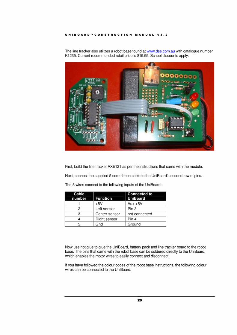
The line tracker also utilizes a robot base found at www.dse.com.au with catalogue number K1235. Current recommended retail price is $19.95. School discounts apply.
First, build the line tracker AXE121 as per the instructions that came with the module.
Next, connect the supplied 5 core ribbon cable to the UniBoard’s second row of pins.
The 5 wires connect to the following inputs of the UniBoard:
Cable number Function
Connected to UniBoard
1 +5V Aux +5V
2 Left sensor Pin 3
3 Center sensor not connected
4 Right sensor Pin 4
5 Gnd Ground
Now use hot glue to glue the UniBoard, battery pack and line tracker board to the robot base. The pins that came with the robot base can be soldered directly to the UniBoard, which enables the motor wires to easily connect and disconnect.
If you have followed the colour codes of the robot base instructions, the following colour wires can be connected to the UniBoard.

U N I B O A R D ™ C O N S T R U C T I O N M A N U A L V 3 . 2
27272727
Sample program:
main:
if pin3 = 1 then left
if pin4 = 1 then right
high 0
high 1
pause 10
low 0
low 1
pause 5
goto main
right:
high 0
pause 10
low 0
pause 5
goto main
left:
high 1
pause 10
low 1
pause 5
goto main

U N I B O A R D ™ C O N S T R U C T I O N M A N U A L V 3 . 2
28282828
Tutorial 8
Infra-Red Communicator
This tutorial shows how one UniBoard can communicate with another UniBoard through invisible Infra Red (IR) light.
Above, one UniBoard is fitted with an IR transmitter, the other is fitted with transmitter and receiver.
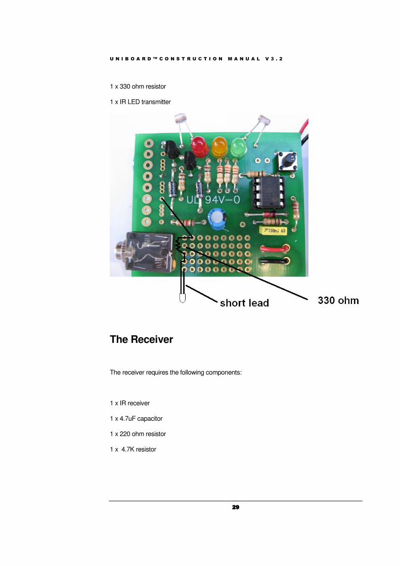
Only two parts are required for the transmitter:
11
U N I B O A R D ™ C O N S T R U C T I O N M A N U A L V 3 . 2
29292929
1 x 330 ohm resistor
1 x IR LED transmitter
The Receiver
The receiver requires the following components:
1 x IR receiver
1 x 4.7uF capacitor
1 x 220 ohm resistor
1 x 4.7K resistor

U N I B O A R D ™ C O N S T R U C T I O N M A N U A L V 3 . 2
30303030
RX Sample Program:
main:
infrain2
if infra = 1 then soundout
goto main
soundout:
sound 2,(100,100)
goto main
TX sample program:
main:
infraout 1,1
pause 500
goto main
The above RX program beeps a piezo speaker every time it receives an IR command. The above TX program continuously transmits an IR signal. By switching on the two boards, a range test should show the boards communicating within 7 or so metres of each other.

U N I B O A R D ™ C O N S T R U C T I O N M A N U A L V 3 . 2
31313131
Tutorial 9
Lie Detector
This tutorial shows how the UniBoard can be made into a simple lie detector. The prototyping area is made into a moisture sensor, where a finger can be applied.
When people tell lies, generally certain signals can be captured and analysed to see if they are telling the truth. This can be in the form of elevated heart beat, heavier breathing, and increased sweating. This kit senses how conductive your finger is, and if you are sweating a lot, it will light up the red LED.
U N I B O A R D ™ C O N S T R U C T I O N M A N U A L V 3 . 2
32323232
Programming the lie detector
Open your programming editor and type in the following program.
main: readadc 4,b1 if b1> 145 then greenlight high 0 wait 1 low 0 goto main greenlight: high 2 wait 1 low 2 goto main
How the program works:
When your finger is on the prototyping area, a small current goes through the 820K resistor, and through your finger to the ground holes. The more sweat on your finger, the lower the analogue signal read by the Picaxe processor. The code simply reads the voltage level at pin 4 using the “readadc” command, and puts it into variable b1. The variable is then tested to see if it is higher than 145. If it is higher than 145, then it is assumed that you are not lying. Hence the green light turns on. If the variable is equal to or lower than 145, then there is a low resistance through your finger, and you are probably lying, hence the red LED turns on. The sample rate is once per second. You can calibrate the lie detector by changing the 145 value to something else. It will be more prone to light the red LED if you increase the value, and will be more prone to light the green LED if you lower the value. Remember that the UniBoard may contain leaded solder; hence you should never lick your fingers to test whether the lie detector is working. Use a damp cloth to wet your fingers instead.

U N I B O A R D ™ C O N S T R U C T I O N M A N U A L V 3 . 2
33333333

Disclaimer and Guarantee
The guarantee on this kit is limited to the replacement of faulty parts only for a
period of 12 months after purchase. The guarantee cannot cover time expenses
or loss of income due to incorrect assembly and/or fault finding and bug fixing.
Note that all electronic components in this kit are from quality suppliers, and it
is extremely unlikely that any part included in this kit is faulty. Check your
soldering; check component placement, resistor values, and batteries carefully.
An incorrectly placed component may not only harm the component, but also
other components in the kit. Before applying power, double-check all
placement of components carefully.
It is recommended that help be sought in the construction of this kit if the
builder believes that the level of electronic knowledge required is out of his/her
domain. Should this help be unavailable, please return the fully sealed kit for a
refund or exchange. Kits cannot be refunded or exchanged after construction
has begun.
Circuit diagram produced and designed in TinyCad. UniBoard is a trademark of APMP. All rights reserved. Picaxe, Rev-Ed, Microchip inc, and TinyCad are trademarks of their respective companies. This document is copyright APMP, 2005. Unauthorised reproduction is prohibited.
10


