ELECTRONIC FUEL INJECTION CONTROLLER FOR NATURAL GAS VEHICLE MOTORCYCLE VANNEBULA EKA INDRAGUNA A thesis submitted in fulfilment of the requirements for the award of the degree of Master of Engineering (Electrical) Faculty of Electrical Engineering Universiti Teknologi Malaysia SEPTEMBER 2006
Transcript
ELECTRONIC FUEL INJECTION CONTROLLER FOR NATURAL GAS
VEHICLE MOTORCYCLE
VANNEBULA EKA INDRAGUNA
A thesis submitted in fulfilment of the
requirements for the award of the degree of
Master of Engineering (Electrical)
Faculty of Electrical Engineering
Universiti Teknologi Malaysia
SEPTEMBER 2006
iii
In The Name of Allah SWT the Most Gracious
and The Most Merciful
“Evil (sins and disobedience of Allah etc) has appeared on land and sea because of
what the hands of men have earned (by oppression and evil deeds, etc), that Allah
may take them taste a part of that which they have done, in order that they may
return (by repenting to Allah, and begging His Pardon)”
(Al-Quran, Ar-Rum:41)
Alhamdulillah. I praise and glorify be only to Allah SWT the Almighty, the Most
Beneficent and the Most Merciful, whose blessings and guidance have helped me
through my study and my life smoothly. There is no power, no strength save in
Allah SWT the Highest, the Greatest. Peace and blessing of Allah SWT be upon to
Rasulullah Muhammad SAW, who has given light to all mankinds in the world.
DEDICATION
This thesis is dedicated to:
My Father, H. Drs. Alamsyah Bakar, and my mother Hj. Rosidah thanks for all of
their love, lots of cares and happiness
My beloved wife Hj. Yusnita Rahayu, ST.,M.Eng, thanks for your patience, kindness
and full support over the entire period of my study.
My beloved mother in law and brother for their support and happiness.
iv
ACKNOWLEDGEMENTS
My thanks go first to my project supervisors, Ir. Prof. Dr. Mohd. Amin Alias.
His guidance and support makes this work possible. I sincerely believe that this work
would not exist without his inspiration. I wish to thank Assoc. Prof. Dr. Zulkiefli
Yacoob for giving me opportunity to come and use the GASTEG engine facility
while pursuing my research. I would also like to thank Assoc. Prof. Dr. Rosli Abu
Bakar who has assisted me in the engine research.
I owe special thanks to my wife, Yusnita Rahayu, ST.,M.Eng. Her constant
encouragements, valuable suggestions, ultimately led to a more thorough were
instrumental in completing this thesis. My thesis would be less without her
participation. I also address special thanks to my friends, Feri Chandra ST., MT and
Ir. Bambang Supriyo MSc, who give so much support and valuable idea. Thanks for
everything that you have given to me.
Finally, the warmest gratitude goes to my father, my mother, my brother, my
friends and colleagues for their willingness to help with any problem that arose, and
have given their moral support in completing my research.
v
ABSTRACT
Smaller vehicles are a major source of both air pollution and congested roads.
The use of natural gas is recommended by the United States Federal Clean Air Act
Amendments of 1990, because it is environmentally friendlier than petrol engine.
Therefore, this thesis presents the design and development of a low cost electronic
fuel injection (EFI) for natural gas vehicle (NGV) motorcycle. The design consists of
signal conditioning, microcontroller systems and the injector drive circuit. The
output of this research is a prototype of EFI which has the capability to control
output engine based on the given mapping table. Two types of mapping table are
used to generate pulse width and timing injection. The first is injection pulse width
corresponding to the rotation per minute (RPM) and manifold absolute pressure
(MAP) and the second is RPM corresponding to encoder angle position. Both of
these mapping tables are accessed concurrently within a single programming which
reduces the use of extra microcontroller and memory. The EFI enables the mixing
and combustion with 17.2:1 (by mass) air to fuel ratio (A/F). In injector
measurement, the first large voltage of 35 V spike at 1.8 msec corresponds to the
reduction in coil current from 4.5 A to 1 A. The pulse width resulted from the
theoretical calculation can be used for the engine experiment between 3000 RPM and
8000 RPM. This is due to the air density value taken by the used formula.
vi
ABSTRAK
Kenderaan kecil merupakan punca utama daripada polusi udara dan
kepadatan jalan raya. Penggunaan natural gas ianya lebih efisien dan ramah
lingkungan berbandingkan pemakaian petrol. Penggunaan natural gas (NG) telah
disyorkan oleh The United States federal Clean Air Act Amendments of 1990,
disebabkan ianya lebih bersahabat dengan lingkungan berbanding pemakaian petrol.
Oleh sebab itu, tesis ini membentangkan reka bentuk dan pembangunan electronic
engine controller pada kendaraan berbahan bakar gas alam. Perekaan meliputi
signal conditioning, sistem mikrokontroler, dan injektor drive. Hasil keluaran yang
diharapkan ialah sebuah reka bentuk prototaip EFI yang boleh mengontrol keluaran
mesin berdasarkan tabel mapping. Terdapat dua macam mapping, yang digunakan
untuk menghasilkan lebar pulsa dan pewaktuan injeksi. Pertama adalah lebar jalur
injeksi berkaitan dengan perputaran setiap menit dan manifold absolute pressure
(MAP) dan kedua adalah perputaran setiap menit berkaitan dengan posisi sudut
encoder. Keduanya ditulis dan dijalankan dalam sebuah program secara bersamaan,
sehingga mengurangkan penggunaan mikrokontroler dan memori. EFI memberikan
pencampuran dan pembakaran dengan 17.2:1 (dengan jisim) pada perbandingan
udara dan bahan api. Pada pengukuran injektor, tegangan keluaran mulai meningkat
pada tegangan 35 V dan pada saat 1.8 msec berterusan dengan menurunnya arus di
dalam koil daripada 4.5 A sampai 1A. Lebar jalur yang dihasilkan daripada
perhitungan teori, boleh digunakan pada percubaan enjin pada kelajuan 3000 RPM
sampai 8000 RPM. Ini disebabkan pada pengambilan nilai air density oleh rumus
yang digunakan.
vii
TABLE OF CONTENTS
CHAPTER SUBJECT PAGE
DECLARATIONS ii
DEDICATION iii
ACKNOWLEDGEMENTS iv
ABSTRACT v
ABSTRAK vi
TABLE OF CONTENTS vii
LIST OF TABLES xi
LIST OF FIGURES xii
LIST OF ABREVIATIONS xiv
LIST OF SYMBOLS xvi
LIST OF APPENDICES xviii
1 INTRODUCTION 1
1.1 Introduction 1
1.2 Research Scope and Objective 2
1.3 Research Background 3
1.4 Problem Statement 6
1.5 Thesis Outlines 7
1.6 Summary 7
viii
2 PRINCIPLE OF ENGINE CONTROLLER 8
2.1 Overall Overview 8
2.2 Overview of Engine Management System 8
2.3 Overview of EEC 9
2.4 EEC Control System Design 11
2.4.1 Open Loop Engine Control System 13
2.4.2 Closed Loop Feedback Control System 13
2.5 Fuel Injection (FI) Concept 14
2.5.1 EFI Functional Block 17
2.5.1.1 Power Supply 18
2.5.1.2 Microcontroller Board 18
2.5.1.3 Speed Microcontroller 20
2.5.1.4 Analogue to Digital Converter 21
2.5.1.5 Injector Driver Controller and
NPN Darlington
21
2.5.2 Fuel Injector Solenoid 22
2.5.3 Air to Fuel Ratio 25
2.5.4 Pulse Width 28
2.5.5 Timing 29
2.6 Parameters Characteristics Requirements 31
2.6.1 Engine Parameters 32
2.6.1.1 Manifold Absolute Pressure 32
2.6.1.2 RPM Signal 34
2.7 Summary 37
ix
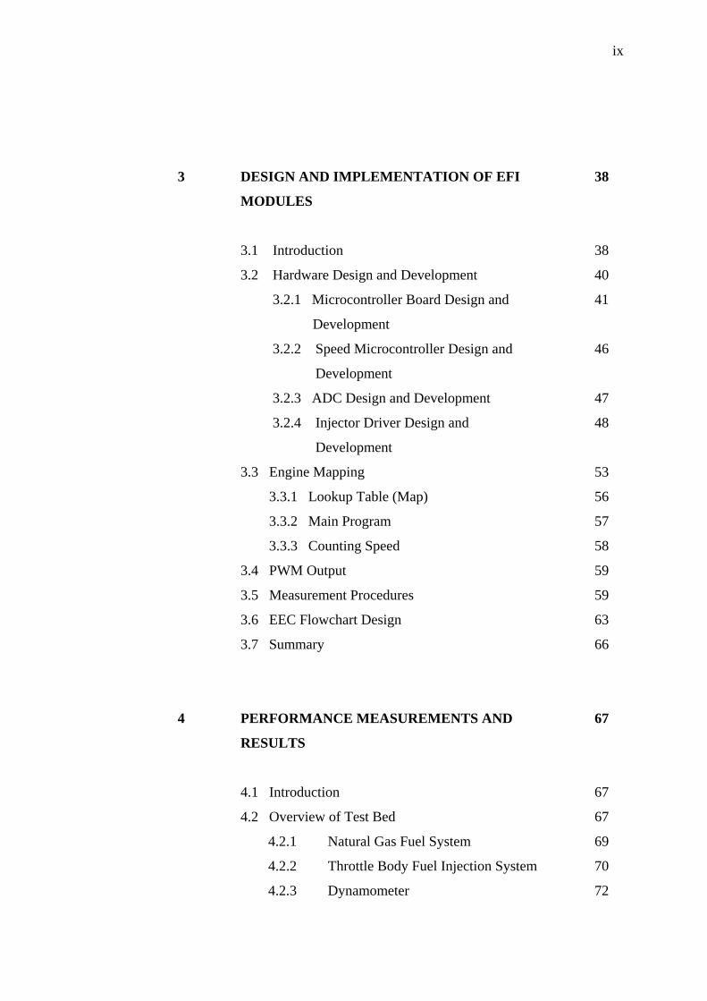
3 DESIGN AND IMPLEMENTATION OF EFI
MODULES
38
3.1 Introduction 38
3.2 Hardware Design and Development 40
3.2.1 Microcontroller Board Design and
Development
41
3.2.2 Speed Microcontroller Design and
Development
46
3.2.3 ADC Design and Development 47
3.2.4 Injector Driver Design and
Development
48
3.3 Engine Mapping 53
3.3.1 Lookup Table (Map) 56
3.3.2 Main Program 57
3.3.3 Counting Speed 58
3.4 PWM Output 59
3.5 Measurement Procedures 59
3.6 EEC Flowchart Design 63
3.7 Summary 66
4 PERFORMANCE MEASUREMENTS AND
RESULTS
67
4.1 Introduction 67
4.2 Overview of Test Bed 67
4.2.1 Natural Gas Fuel System 69
4.2.2 Throttle Body Fuel Injection System 70
4.2.3 Dynamometer 72
x
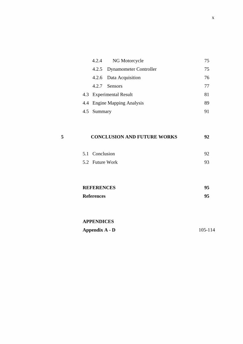
4.2.4 NG Motorcycle 75
4.2.5 Dynamometer Controller 75
4.2.6 Data Acquisition 76
4.2.7 Sensors 77
4.3 Experimental Result 81
4.4 Engine Mapping Analysis 89
4.5 Summary 91
5 CONCLUSION AND FUTURE WORKS 92
5.1 Conclusion 92
5.2 Future Work 93
REFERENCES 95
References 95
APPENDICES
Appendix A - D 105-114
xi
LIST OF TABLES
NO. TABLE TITLE PAGE
3.1 Component values of injector driver circuit 52
3.2 Injection pulse width corresponds to the RPM and MAP
(theoretical)
55
3.3 Injection pulse width corresponds to the RPM and MAP 56
3.4 RPM corresponds to encoder angle position 56
4.1 Engine parameters 89
4.2 Injection pulse width corresponds to the RPM and MAP
(experimental)
90
xii
LIST OF FIGURES
NO. TABLE TITLE PAGE
2.1 General block diagram of an ignition and fuel control
system
10
2.2 A system boundary 11
2.3 Open loop control system 13
2.4 Closed loop feedback control system 14
2.5 Reduction in sensors implementation for Yamaha large
model FJR1300
16
2.6 Overall EFI functional block 17
2.7 Injector solenoid 23
2.8 Equivalent injector circuit model 24
2.9 Solenoid operated actuator variables 25
2.10 The stoichiometric A/F mixture 27
2.11 Four stroke cycle engine 30
2.12 Pulse width relative to crank angle 31
2.13 Inductive sensors 36
2.14 Hall effect sensor in a distributor 37
3.1 Main microcontroller board of 89S52 41
3.2 Circuit Diagram of 89S52 42
3.3 Main microcontroller board of 89C51 43
3.4 Circuit Diagram of 89C51 43
3.5 Speed microcontroller circuit design 46
3.6 Speed microcontroller board of AT 89C2051 47
3.7 Injector drive controller and NPN Darlington 49
3.8 Injector driver board 51
xiii
3.9 Injector voltage waveform showing pimple bump when
closing
61
3.10 Injector current waveform showing pimple bump when
opening
61
3.11 EFI design flowchart 64
3.12 EFI programmer flowchart 65
4.1 Overall test bed 68
4.2 NG delivery system design 70
4.3 Digitally controlled fuel injection of throttle body 71
4.4 Placement of throttle body in the single cylinder small
engine motorcycle
72
4.5 Dynamometer development (front view) 74
4.6 Dynamometer alignment work (side view) 74
4.7 Conceptual dynamometer controller process 76
4.8 Sensors integration with engine and EFI 77
4.9 MAP sensor voltage signal 78
4.10 Crankshaft and camshaft position signal 79
4.11 MAP sensor (analog) waveform 80
4.12 MAP sensor (digital) waveform 80
4.13 Measurement procedures of injector output voltage 81
4.14 The injector voltage waveform in terms of rise time 82
4.15 Injector input pulse width of 26 msec 83
4.16 Injector pulse width of 16 msec 84
4.17 The output voltage waveform at Pin 2 85
4.18 The output voltage waveform of 5 V 85
4.19 The RPM waveform corresponds to the MAP and pulse
width (minimum value)
86
4.20 The RPM waveform corresponds to the MAP and pulse
width (maximum value)
87
4.21 The RPM waveform corresponds to the MAP and pulse
width (minimum value)
88
xiv
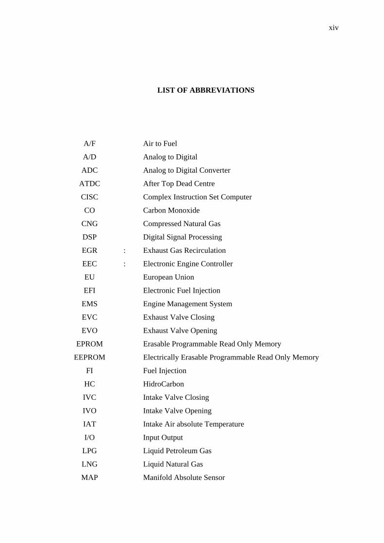
LIST OF ABBREVIATIONS
A/F Air to Fuel
A/D Analog to Digital
ADC Analog to Digital Converter
ATDC After Top Dead Centre
CISC Complex Instruction Set Computer
CO Carbon Monoxide
CNG Compressed Natural Gas
DSP Digital Signal Processing
EGR : Exhaust Gas Recirculation
EEC : Electronic Engine Controller
EU European Union
EFI Electronic Fuel Injection
EMS Engine Management System
EVC Exhaust Valve Closing
EVO Exhaust Valve Opening
EPROM Erasable Programmable Read Only Memory
EEPROM Electrically Erasable Programmable Read Only Memory
FI Fuel Injection
HC HidroCarbon
IVC Intake Valve Closing
IVO Intake Valve Opening
IAT Intake Air absolute Temperature
I/O Input Output
LPG Liquid Petroleum Gas
LNG Liquid Natural Gas
MAP Manifold Absolute Sensor
xv
NG Natural Gas
NGV Natural Gas Vehicle
NPN Negative-Positive-Negative
NV Non Volatile
PROM Programmable Read Only Memory
PW Pulse Width
PWM Pulse Width Modulation
PCB Printed Circuit Board
RISC : Reduced Instruction Set Computer
ROM Read Only Memory
RAM : Random Access Memory
RPM Revolution Per Minute
RPS Revolution Per Second
SMEC : Single Module Engine Controller
SBEC : Single Board Engine Controller
SLSD Sea Level on Standard Day
TDC : Top Dead Centre
xvi
LIST OF SYMBOLS
do Absolute intake density
da Intake air density
D Engine displacement
F Fuel
f Input frequency
fMAX Maximum frequency
fMIN Minimum frequency
hFE Current gain
I Current
Ic Collector current
IB Base current
L1 Injector inductance
mi Mass of air within the intake manifold
N Variable
nV Volumetric efficiency
p Intake manifold pressure
PQ Power comsumption
po Absolute pressure
Rf - Flow rate
RV Volume flow rate
Rm Flow rate of air
Rfm Mass flow rate
RL Resistive load
RS Sense resistor
R1 Injector resistance
SFR Static flow rate
xvii
T - Temperature
To Absolute temperature
Ti Intake manifold air temperature
thigh High period
tlow Low period
t Time
Vi Volume of the intake manifold
VCE Voltage between collector and emitter
VCC Voltage collector
VH Sense input hold voltage
VP Sense input peak voltage
VZ Zener breakdown
VBATT Battery voltage
ρi - Pressure in the intake manifold
xviii
LIST OF APPENDICES
APPENDIX TITLE PAGE
A Main microcontroller board circuit 103
B Assembly language program 104
C Modenass Kriss 110 cc specifications 111
D List of Publications 112
CHAPTER 1
INTRODUCTION
1.1 Introduction
The engine was the first major sub system of the vehicle to be turned over
from mechanical to electronic control. Engine electronics was introduced in the
1970s for the control of ignition and exhaust gas recirculation (EGR) in gasoline
engines [1]. In the 70's, engines relied on mechanically generated signals to ignite
the fuel/air mixture.
Since that time, engine electronic controller (EEC) system has developed and
changed greatly. In 1977, EEC II was introduced by Delco Remy [1]. It gave
accuracy and flexibility and offered other advantages such as a reduced part count
and a lower maintenance burden than its mechanical forebears. It was also as a
response to the oil crisis and promised marginally better fuel economy.
Electronic controls have significantly improved engine performances relative
to mechanical controls. The use of digital electronic control has also enabled this
engine to meet the government regulations on exhaust emission and fuel economy by
controlling the system accurately with excellent tolerance and flexibility.
EEC III was introduced in 1979 on the Lincoln Continental [2]. The most
significant single change for EEC IV, 1982-1985, is the introduction of the
diagnostic requirements [3]-[5]. The implementation of these requirements is
2
estimated to have doubled the use of resources, measured in memory usage and
processor throughput. The type of microcomputer is significantly different. A
complex instruction set computer (CISC) 8 bit micro-computer has given way to a 32
bit reduced instruction set computer (RISC) device [2]. The increasing demand for
functions and the legislative requirement have driven the pace of change and have
forced changes in the system architecture.
In this thesis, An EEC for controlling the fuel injection is purposed and this is
called as electronic fuel injection (EFI) controller. This prototype concerns on fuel
injection problem and it consists of two modules such as logic module and power
module. The separation is based on its function and signal generated. The logic
module consisting of microcontroller and analog to digital converter (A/D) is
responsible for signals processing from manifold absolute pressure (MAP) sensor.
The power module consisting of Darlington transistor, injection driver and voltage
regulator is responsible for producing the fuel injector pulses by regulating the
alternator field coil to maintain proper voltage levels.
Basically, this electronic controller design is similar for gasoline, diesel,
natural gas (NG), and alcohol powered engines, as well as hybrid-powered engines, a
variety of cylinder, and fuel-delivery configurations. Principle of engine controller
will be explained more detail in chapter II.
1.2 Research Scope and Objective
The goal of this thesis is to design and develop a low cost EFI for NG
motorcycle application. The scope of work includes identifying the subsystem and
integrating all subsystems into a complete EFI system. The EFI is measured in terms
of input and output signals to meet the parameter requirements, hardware and
software. For developing and testing mapping, the EFI prototype will be integrated
with NG motorcycle engine and dynamometer to observe and determine its
performance in terms of fuel injection problem.
3
This work offers the promise of an engine control system which is fully
adaptive to changes in fuel flame speed caused by variable fuel (NG and gasoline)
[6], operating conditions, engine wear, or other factors. The result of this project is
expected to be used with more upgraded mechanical system for better system
performance. Therefore the control system should be as flexible as possible so that
the changes can be done through modifying the software with minimal modification
in hardware. Thus the use of microcontroller is the best choice for this control