Safety Considerations ................................................................................................................. 4Introduction BIS C.................................................................................................................... 5/6Application BIS C-600 ................................................................................................................ 7Configuration ......................................................................................................................... 8-22User Configuration ............................................................................................................... 23-26Protocol ................................................................................................................................ 27/28Read/Write Times ................................................................................................................. 29/30Programming ....................................................................................................................... 31-48Error Numbers ...................................................................................................................... 49/50Interface ............................................................................................................................... 51-54Assembly of Read/Write Head/Processor ........................................................................... 55-57Technical Data ...................................................................................................................... 58/59Ordering Information ................................................................................................................. 60ASCII Table ................................................................................................................................ 61
Contents
C600-024_0011_E.P65
4
4 E
Safety Considerations
BIS C-600 processors together with the other BIS C system components comprise theIdentification System and may be used only for this purpose.
Installation and operation should be carried out by technicall trained personnel only. Unau-thorized access and improper use will lead to loss of warranty and liability claims.
When installing the processor, consult the section on wiring diagrams carefully. Specialcaution must be used when wiring the processor to external controllers, particularly withrespect to selection and polarity of the signals and power supply.
Only approved power supplies may be used with the processor. See the section on TechnicalData for details.
The relevant safety procedures must be followed when using the Identification System. Inparticular, steps must be taken to ensure that no danger to persons or equipment can ariseshould a fault occur in the Identification System.
This includes maintaining the published ambient operating conditions and regular checking ofthe functionality of the Identification System with all its associated components.
As soon as there is evidence that the Identification System is not functioning properly, itshould be taken out of service and protected against unauthorized use.
This description is valid for processors in the series BIS C-600-024-...-04-KL1.
Installation andOperation
Use and Checking
Fault Conditions
Scope
5
5E
Applications
Principles
This manual is designed to assist the user in setting up the control program and installing andstarting up the components of the BIS C-600 Identification System, and to assure rapid,trouble-free operation.
The BIS C-600 Identification System belongs in the category of
non-contact systems for reading and writing.
This dual function permits applications for not only transporting information in fixed-pro-grammed code tags, but also for gathering and passing along up-to-date information as well.
Some of the notable areas of application include
– for controlling material flow in production processes(e.g. in model-specific processes),for workpiece conveying in transfer lines,in data gathering for quality assurance ,for gathering satety-related data,
– in tool coding and monitoring;
– in equipment organization;
– in storage systems for monitoring inventory movement;
– in transporting and conveying systems;
– in waste management for quantity-based fee assessment.
IntroductionBIS C Identification System
C600-024_0011_E.P65
6
6 E
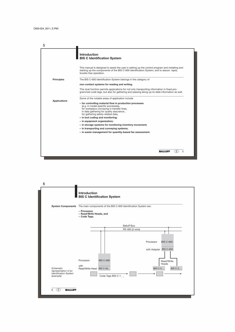
System Components The main components of the BIS C-600 Identification System are:
– Processor,– Read/Write Heads, and– Code Tags.
IntroductionBIS C Identification System
Code Tags BIS C-1_ _
Processor BIS C-600
withRead/Write HeadSchematic
representation of anIdentification System(example)
Read/WriteHeads
Processor BIS C-600
with Adapter
Balluff Bus
RS 485 (2-wire)
7
7E
Selecting SystemComponents
A BIS C-600 processor may be used with a single series BIS C-65_ read/write head directlyattached, comprising a compact unit. A second, series BIS C-3_ _ read/write head with 5m ofcable (except BIS C-350 and -352) may be cable connected to the BIS C-600.
If the BIS C-600 processor is fitted with the BIS C-650 adapter instead of a BIS C-65_read/write head, two (2) series BIS C-3_ _ read/write heads may be cable attached (exceptBIS C-350 and -352).
For additional information concerning series BIS C-65_ and BIS C3_ _ read/write headstogether with suitable combinations of code tags, consult the manuals for the respectiveread/write heads.
Which of the above described arrangements of read/write heads is the most logical will bedetermined mainly by the spatial arrangement of the components. There are no functionallimitations. All read/write heads are suitable for both static and dynamic reading and writing.Sensing distance and traverse velocity will depend on the individual code tag(s).
The system components are electrically powered by the processor. The code tag represents astand-alone unit, and does not require an external source of power. It receives its energy fromthe read/write head. The latter sends a constant carrier signal which supplies the code tag assoon as the required sensing distance is reached. The read/write process takes place duringthis phase. Reading and writing may be static or dynamic.
ApplicationBIS C-600 Processor
C600-024_0011_E.P65
8
8 E
Configuration
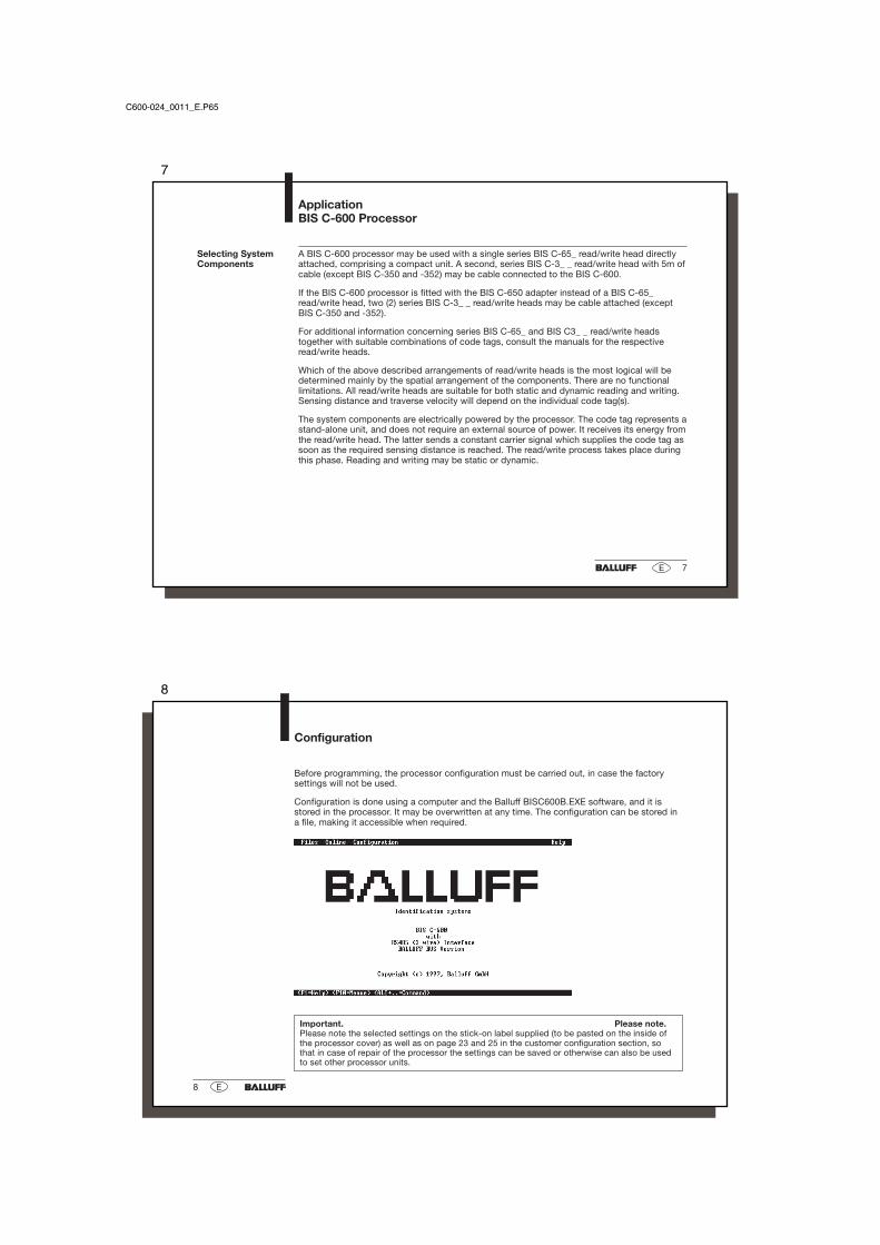
Important. Please note.Please note the selected settings on the stick-on label supplied (to be pasted on the inside ofthe processor cover) as well as on page 23 and 25 in the customer configuration section, sothat in case of repair of the processor the settings can be saved or otherwise can also be usedto set other processor units.
Before programming, the processor configuration must be carried out, in case the factorysettings will not be used.
Configuration is done using a computer and the Balluff BISC600B.EXE software, and it isstored in the processor. It may be overwritten at any time. The configuration can be stored ina file, making it accessible when required.
< Next > < Shortform > < ESC = Exit > < Print . . . . > < F1 = Help >
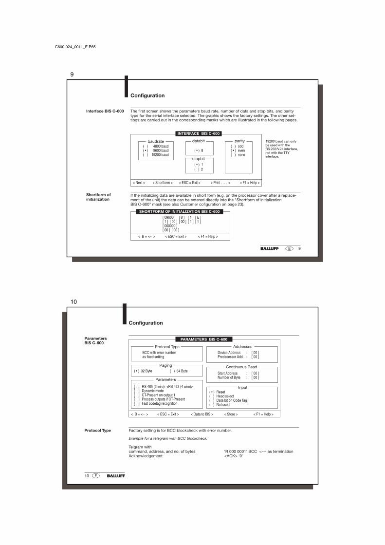
19200 baud can onlybe used with theRS 232/V.24 interface,not with the TTYinterface.
baudrate
INTERFACE BIS C-600
If the initializing data are available in short form (e.g. on the processor cover after a replace-ment of the unit) the data can be entered directly into the "Shortform of initializationBIS C-600" mask (see also Customer cofiguration on page 23).
The first screen shows the parameters baud rate, number of data and stop bits, and paritytype for the serial interface selected. The graphic shows the factory settings. The other set-tings are carried out in the corresponding masks which are illustrated in the following pages.
Shortform ofinitialization
C600-024_0011_E.P65
10
10 E
Configuration
< B = <– > < ESC = Exit > < Data to BIS > < Store > < F1 = Help >
Protocol Type
Parameters
[ ] RS 485 (2 wire) <RS 422 (4 wire)>[ ] Dynamic mode[ ] CT-Present on output 1[ ] Process outputs if CT-Present[ ] Fast codetag recognition
( • ) 32 Byte ( ) 64 Byte
PARAMETERS BIS C-600
( • ) Reset( ) Head select( ) Data bit on Code Tag( ) Not used
Paging
Input
Factory setting is for BCC blockcheck with error number.
Example for a telegram with BCC blockcheck:
Telgram withcommand, address, and no. of bytes: 'R 000 0001' BCC <--- as terminationAcknowledgement: <ACK> '0'
BCC with error numberas fixed setting
Device Address : [ 00 ]Predecessor Add. : [ 00 ]
Addresses
ParametersBIS C-600
Protocol Type
Start Address : [ 00 ]Number of Byte : [ 00 ]
Continuous Read
11
11E
Parameters
Configuration
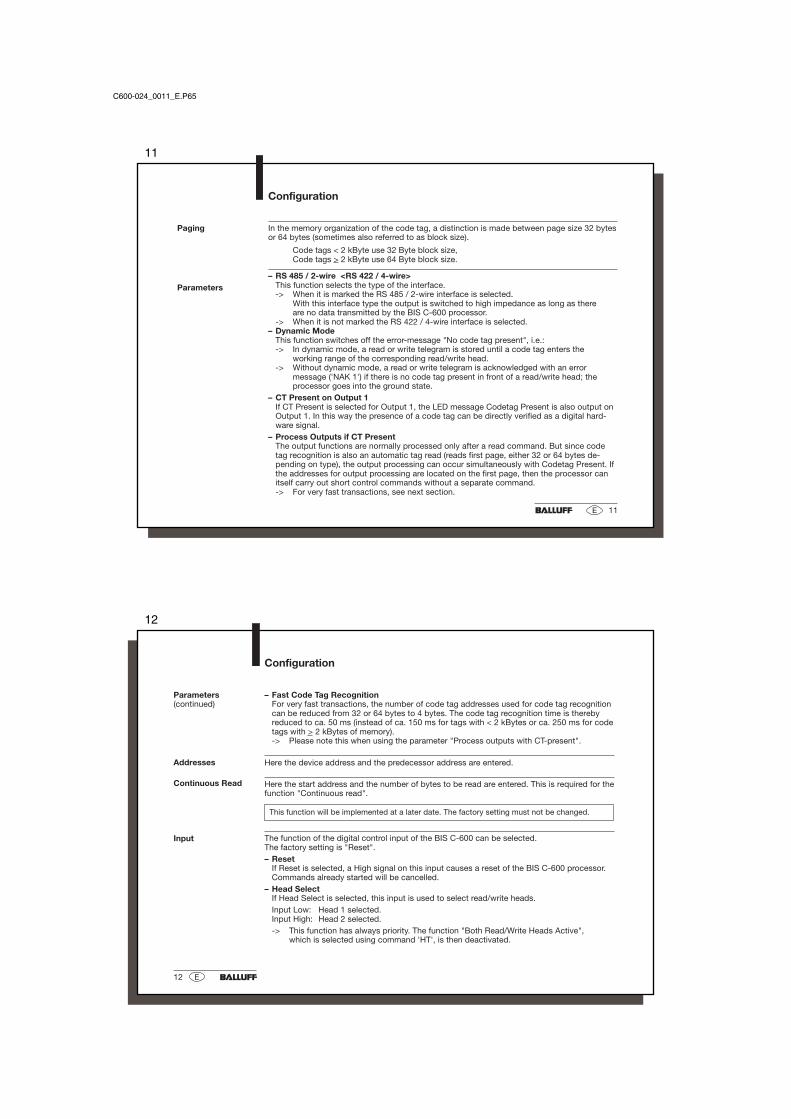
In the memory organization of the code tag, a distinction is made between page size 32 bytesor 64 bytes (sometimes also referred to as block size).
Code tags < 2 kByte use 32 Byte block size,Code tags > 2 kByte use 64 Byte block size.
– RS 485 / 2-wire <RS 422 / 4-wire>This function selects the type of the interface.-> When it is marked the RS 485 / 2-wire interface is selected.
With this interface type the output is switched to high impedance as long as thereare no data transmitted by the BIS C-600 processor.
-> When it is not marked the RS 422 / 4-wire interface is selected.– Dynamic Mode
This function switches off the error-message "No code tag present", i.e.:-> In dynamic mode, a read or write telegram is stored until a code tag enters the
working range of the corresponding read/write head.-> Without dynamic mode, a read or write telegram is acknowledged with an error
message ('NAK 1') if there is no code tag present in front of a read/write head; theprocessor goes into the ground state.
– CT Present on Output 1If CT Present is selected for Output 1, the LED message Codetag Present is also output onOutput 1. In this way the presence of a code tag can be directly verified as a digital hard-ware signal.
– Process Outputs if CT PresentThe output functions are normally processed only after a read command. But since codetag recognition is also an automatic tag read (reads first page, either 32 or 64 bytes de-pending on type), the output processing can occur simultaneously with Codetag Present. Ifthe addresses for output processing are located on the first page, then the processor canitself carry out short control commands without a separate command.-> For very fast transactions, see next section.
Paging
C600-024_0011_E.P65
12
12 E
Configuration
– Fast Code Tag RecognitionFor very fast transactions, the number of code tag addresses used for code tag recognitioncan be reduced from 32 or 64 bytes to 4 bytes. The code tag recognition time is therebyreduced to ca. 50 ms (instead of ca. 150 ms for tags with < 2 kBytes or ca. 250 ms for codetags with > 2 kBytes of memory).-> Please note this when using the parameter "Process outputs with CT-present".
Here the device address and the predecessor address are entered.
Here the start address and the number of bytes to be read are entered. This is required for thefunction "Continuous read".
This function will be implemented at a later date. The factory setting must not be changed.
The function of the digital control input of the BIS C-600 can be selected.The factory setting is "Reset".– Reset
If Reset is selected, a High signal on this input causes a reset of the BIS C-600 processor.Commands already started will be cancelled.
– Head SelectIf Head Select is selected, this input is used to select read/write heads.Input Low: Head 1 selected.Input High: Head 2 selected.-> This function has always priority. The function "Both Read/Write Heads Active",
which is selected using command 'HT', is then deactivated.
Input
Addresses
Parameters(continued)
Continuous Read
13
13E
– Data bit on Code tagOn recognition of a new code tag a freely definable bit of a given address will be written,direct or inverted, on the code tag. After a succesful write operation, an output which canalso be freely defined is set until the code tag leaves the active read/write range.-> The parameter "Dynamic operation" will be automatically reset.
– Not usedThe input has no function.
Configuration
Input(continued)
C600-024_0011_E.P65
14
14 E
Configuration
Input/OutputConfiguration
The outputs can be configured for various functions. The output functions are always pro-cessed during a read. Prerequisite for the execution is that the corresponding address wasread during the previous read operation.
IN/OUTPUT CONFIGURATION
< OK > < Shortform > < ESC = Exit > < Print . . . . > < F1 = Help >
( • ) Outputs not used.( ) Output halfbyte of data contents of an address.( ) Compare contents of multiple addresses with a fixed value.( ) Compare contents of an address with various fixed values.( ) Compare contents of multiple addresses with content of one address.( ) Output data bits of variable addresses.
( ) Program input as data bit to code tag.
"Data to BIS" transmits the data to the processor. "Store" stores the data in the configurationfile on your computer.
"Outputs not used" means processing of the outputs is deactivated.Outputs not used
15
15E
Configuration
Output Halfbyte ofthe Data Contents ofan Address
< OK > < Shortform > < ESC = Exit > < Print . . . . > < F1 = Help >
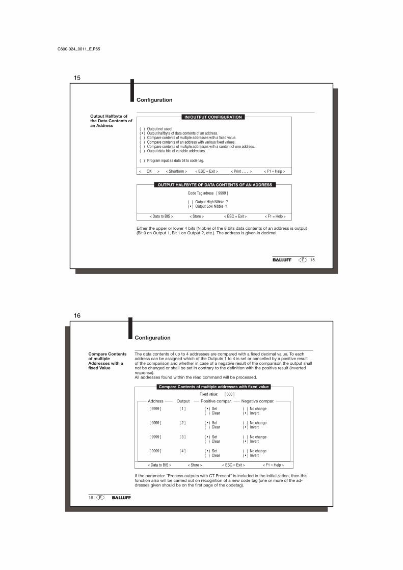
( ) Output not used.( • ) Output halfbyte of data contents of an address.( ) Compare contents of multiple addresses with a fixed value.( ) Compare contents of an address with various fixed values.( ) Compare contents of multiple addresses with a content of one address.( ) Output data bits of variable addresses.
( ) Program input as data bit to code tag.
Either the upper or lower 4 bits (Nibble) of the 8 bits data contents of an address is output(Bit 0 on Output 1, Bit 1 on Output 2, etc.). The address is given in decimal.
Code Tag adress [ 9999 ]
( ) Output High Nibble ?( • ) Output Low Nibble ?
< Data to BIS > < Store > < ESC = Exit > < F1 = Help >
OUTPUT HALFBYTE OF DATA CONTENTS OF AN ADDRESS
IN/OUTPUT CONFIGURATION
C600-024_0011_E.P65
16
16 E
Configuration
Compare Contentsof multipleAddresses with afixed Value
The data contents of up to 4 addresses are compared with a fixed decimal value. To eachaddress can be assigned which of the Outputs 1 to 4 is set or cancelled by a positive resultof the comparison and whether in case of a negative result of the comparison the output shallnot be changed or shall be set in contrary to the definition with the positive result (invertedresponse).All addresses found within the read command will be processed.
[ 9999 ] [ 1 ] ( • ) Set ( ) No change( ) Clear ( • ) Invert
[ 9999 ] [ 2 ] ( • ) Set ( ) No change( ) Clear ( • ) Invert
[ 9999 ] [ 3 ] ( • ) Set ( ) No change( ) Clear ( • ) Invert
[ 9999 ] [ 4 ] ( • ) Set ( ) No change( ) Clear ( • ) Invert
Negative compar.Output Positive compar.
< Data to BIS > < Store > < ESC = Exit > < F1 = Help >
Fixed value: [ 000 ]
Address
Compare Contents of multiple addresses with fixed value
If the parameter "Process outputs with CT-Present" is included in the initialization, then thisfunction also will be carried out on recognition of a new code tag (one or more of the ad-dresses given should be on the first page of the codetag).
17
17E
Configuration
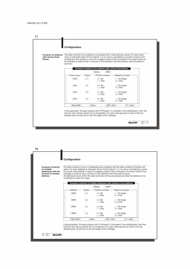
Compare an Addresswith various fixedValues
The data contents of an address is compared with 4 fixed decimal values. For each fixedvalue is indicated which of the Outputs 1 to 4 is set or cancelled by a positive result of thecomparison and whether in case of a negative result of the comparison the output shall notbe changed or shall be set in contrary to the definition with the positive result (inverted re-sponse).
[ 000 ] [ 1 ] ( • ) Set ( ) No change( ) Clear ( • ) Invert
[ 000 ] [ 2 ] ( • ) Set ( ) No change( ) Clear ( • ) Invert
[ 000 ] [ 3 ] ( • ) Set ( ) No change( ) Clear ( • ) Invert
[ 000 ] [ 4 ] ( • ) Set ( ) No change( ) Clear ( • ) Invert
Negative compar.Output Positive compar.
< Data to BIS > < Store > < ESC = Exit > < F1 = Help >
Address: [ 9999 ]
Compare contents of an address with various fixed Values
Fixed value
If the parameter "Process outputs with CT-Present" is included in the inititialization, then thisfunction also will be carried out on recognition of a new code tag (one or more of the ad-dresses given should be on the first page of the codetag).
C600-024_0011_E.P65
18
18 E
Configuration
Compare Contentsof multipleAddresses with theContent of anotherAddress
The data contents of up to 4 addresses are compared with the data contents of another ad-dress. For each address is indicated which of the Outputs 1 to 4 is set or cancelled by a posi-tive result and whether in case of a negative result of the comparison the output shall not bechanged or shall be set in contrary to the definition with the positive result.All addresses found within the read command will be processed provided the address to becompared is within the range.
< Data to BIS > < Store > < ESC = Exit > < F1 = Help >
[ 9999 ] [ 1 ] ( • ) Set ( ) No change( ) Clear ( • ) Invert
[ 9999 ] [ 2 ] ( • ) Set ( ) No change( ) Clear ( • ) Invert
[ 9999 ] [ 3 ] ( • ) Set ( ) No change( ) Clear ( • ) Invert
[ 9999 ] [ 4 ] ( • ) Set ( ) No change( ) Clear ( • ) Invert
Negative compar.Output Positive compar.Address
Address: [ 9999 ]
Compare contents of multiple addresses with content of one address
If the parameter "Process outputs with CT-Present" is included in the inititialization, then thisfunction also will be carried out on recognition of a new code tag (one or more of the ad-dresses given should be on the first page of the codetag).
19
19E
Configuration
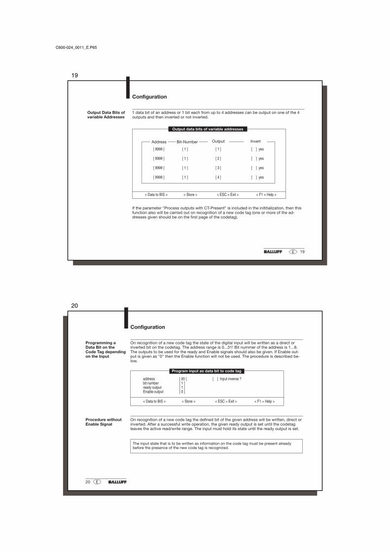
Output Data Bits ofvariable Addresses
1 data bit of an address or 1 bit each from up to 4 addresses can be output on one of the 4outputs and then inverted or not inverted.
[ 9999 ] [ 1 ] [ 1 ] [ ] yes
[ 9999 ] [ 1 ] [ 2 ] [ ] yes
[ 9999 ] [ 1 ] [ 3 ] [ ] yes
[ 9999 ] [ 1 ] [ 4 ] [ ] yes
Address OutputBit-Number
< Data to BIS > < Store > < ESC = Exit > < F1 = Help >
Output data bits of variable addresses
Invert
If the parameter "Process outputs with CT-Present" is included in the inititialization, then thisfunction also will be carried out on recognition of a new code tag (one or more of the ad-dresses given should be on the first page of the codetag).
C600-024_0011_E.P65
20
20 E
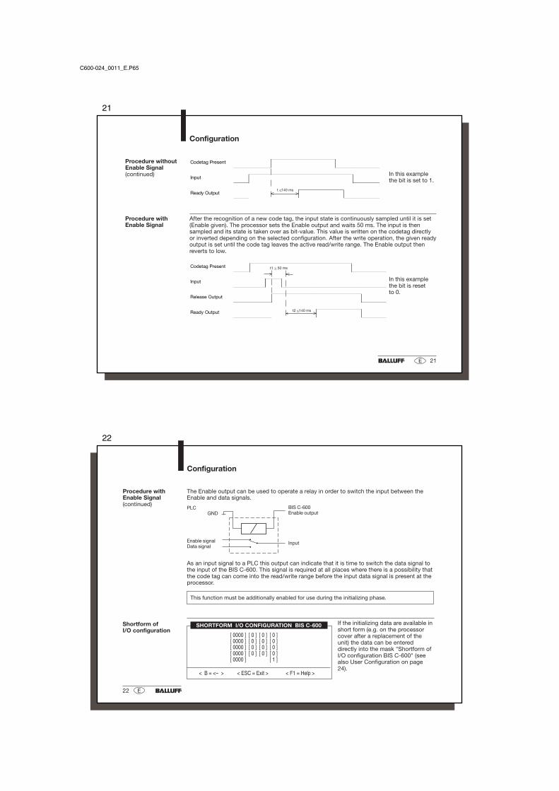
On recognition of a new code tag the defined bit of the given address will be written, direct orinverted. After a successful write operation, the given ready output is set until the codetagleaves the active read/write range. The input must hold its state until the ready output is set.
The input state that is to be written as information on the code tag must be present alreadybefore the presence of the new code tag is recognized.
Configuration
Programming aData Bit on theCode Tag dependingon the Input
On recognition of a new code tag the state of the digital input will be written as a direct orinverted bit on the codetag. The address range is 0...31! Bit nummer of the address is 1...8.The outputs to be used for the ready and Enable signals should also be given. If Enable out-put is given as "0" then the Enable function will not be used. The procedure is described be-low.
< Data to BIS > < Store > < ESC = Exit > < F1 = Help >
Program input as data bit to code tag
Procedure withoutEnable Signal
21
21E
Codetag Present
Input
Ready Output
In this examplethe bit is set to 1.
In this examplethe bit is resetto 0.
Configuration
Codetag Present
Input
Release Output
Ready Output
t1 > 50 ms
t2 <140 ms
t <140 ms
After the recognition of a new code tag, the input state is continuously sampled until it is set(Enable given). The processor sets the Enable output and waits 50 ms. The input is thensampled and its state is taken over as bit-value. This value is written on the codetag directlyor inverted depending on the selected configuration. After the write operation, the given readyoutput is set until the code tag leaves the active read/write range. The Enable output thenreverts to low.
If the initializing data are available inshort form (e.g. on the processorcover after a replacement of theunit) the data can be entereddirectly into the mask "Shortform ofI/O configuration BIS C-600" (seealso User Configuration on page24).
The Enable output can be used to operate a relay in order to switch the input between theEnable and data signals.
PLCGND
Enable signalData signal
BIS C-600Enable output
Input
As an input signal to a PLC this output can indicate that it is time to switch the data signal tothe input of the BIS C-600. This signal is required at all places where there is a possibility thatthe code tag can come into the read/write range before the input data signal is present at theprocessor.
This function must be additionally enabled for use during the initializing phase.
Configuration
Procedure withEnable Signal(continued)
Shortform ofI/O configuration
23
23E
User Configuration
Initialization Please note the settings in the label fields on the inside of the processor cover so that in caseof repair of the processor the settings can be reset in the factory. Note the settings also in thefollowing fields so that you can set, e.g. other units, to an identical configuration.
On the following page you will find an example which shows how you can print-out afterinitializing. Enter the settings in the appropriate fields so that you have them handy and canreproduce the settings at any time. You can then enter the data in short form into the mask.(see also page 9).
00 00 The fields crossed out must not be changed as long asthe function "Continuous read" is not realized.
BaudrateDatabits
Stopbits
Pa-rity
Interface
Device address Block size
Protocol type 1
Predecessor address Input
Parameters
Number of bytes
C600-024_0011_E.P65
24
24 E
1 9 2 0 0 8 1 N
1 15 14 2 1
0 0 0 0 0 1
Initialization(continued)
Example of a print-out after initialization which you can print with the softwareBISC600B.EXE.
Interface settingsBaudrate : 19200 baudData bits : 8Stop bits : 1Parity : NoneProtocolBCC with error numberAddressesDevice address : 15Predecessor add. : 14Continuous readStart address : 00 *)Number of bytes : 00 *)Parameter[ ] RS485/2-wire <RS422/4-wire>[ ] Dynamic mode[ ] Codetag Present signal on Output 1[ ] Process outputs with Codetag Present[ X ] Fast codetag recognitionBlock size( ) 32 Byte page size( * ) 64 Byte page sizeInput( * ) Input = Reset( ) Input = Head select( ) Input = data bit on code tag( ) Input = not used
The entries in the field are either in clear text (aswith Interface settings) or the number of the linemarked. In the case of 'Parameter' the marked lineis indicated by a 1.
User Configuration
00 00*) *)
*) As long as the function "Continuousread" is not realized, these fieldsmust not be changed.
25
25E
User Configuration
Input/OutputConfiguration
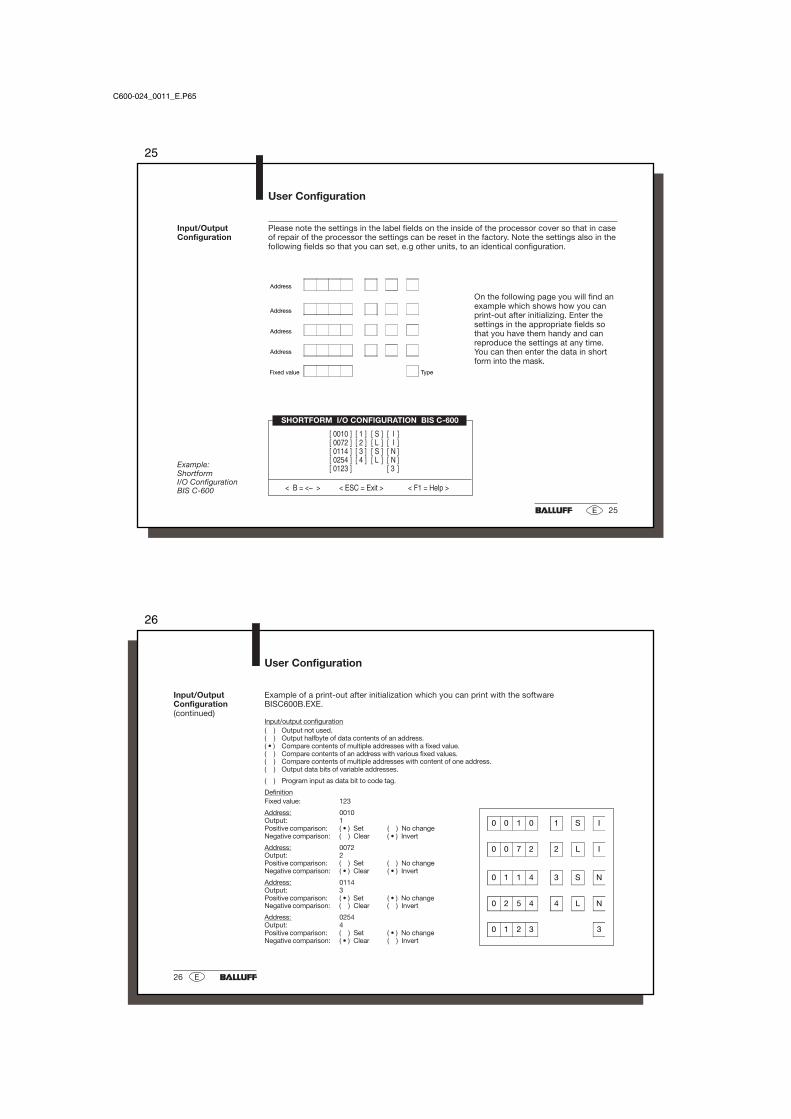
Please note the settings in the label fields on the inside of the processor cover so that in caseof repair of the processor the settings can be reset in the factory. Note the settings also in thefollowing fields so that you can set, e.g other units, to an identical configuration.
On the following page you will find anexample which shows how you canprint-out after initializing. Enter thesettings in the appropriate fields sothat you have them handy and canreproduce the settings at any time.You can then enter the data in shortform into the mask.
SHORTFORM I/O CONFIGURATION BIS C-600
[ 0010 ] [ 1 ] [ S ] [ I ][ 0072 ] [ 2 ] [ L ] [ I ][ 0114 ] [ 3 ] [ S ] [ N ][ 0254 ] [ 4 ] [ L ] [ N ][ 0123 ] [ 3 ]
< B = <– > < ESC = Exit > < F1 = Help >
Example:ShortformI/O ConfigurationBIS C-600
Address
Address
Address
Address
Fixed value Type
C600-024_0011_E.P65
26
26 E
Example of a print-out after initialization which you can print with the softwareBISC600B.EXE.
Input/output configuration( ) Output not used.( ) Output halfbyte of data contents of an address.( • ) Compare contents of multiple addresses with a fixed value.( ) Compare contents of an address with various fixed values.( ) Compare contents of multiple addresses with content of one address.( ) Output data bits of variable addresses.
( ) Program input as data bit to code tag.
DefinitionFixed value: 123
Address: 0010Output: 1Positive comparison: ( • ) Set ( ) No changeNegative comparison: ( ) Clear ( • ) Invert
Address: 0072Output: 2Positive comparison: ( ) Set ( ) No changeNegative comparison: ( • ) Clear ( • ) Invert
Address: 0114Output: 3Positive comparison: ( • ) Set ( • ) No changeNegative comparison: ( ) Clear ( ) Invert
Address: 0254Output: 4Positive comparison: ( ) Set ( • ) No changeNegative comparison: ( • ) Clear ( ) Invert
Input/OutputConfiguration(continued)
0 0 1 0 1 S I
0 0 7 2 2 L I
0 1 1 4 3 S N
0 2 5 4 4 L N
0 1 2 3 3
User Configuration
27
27E
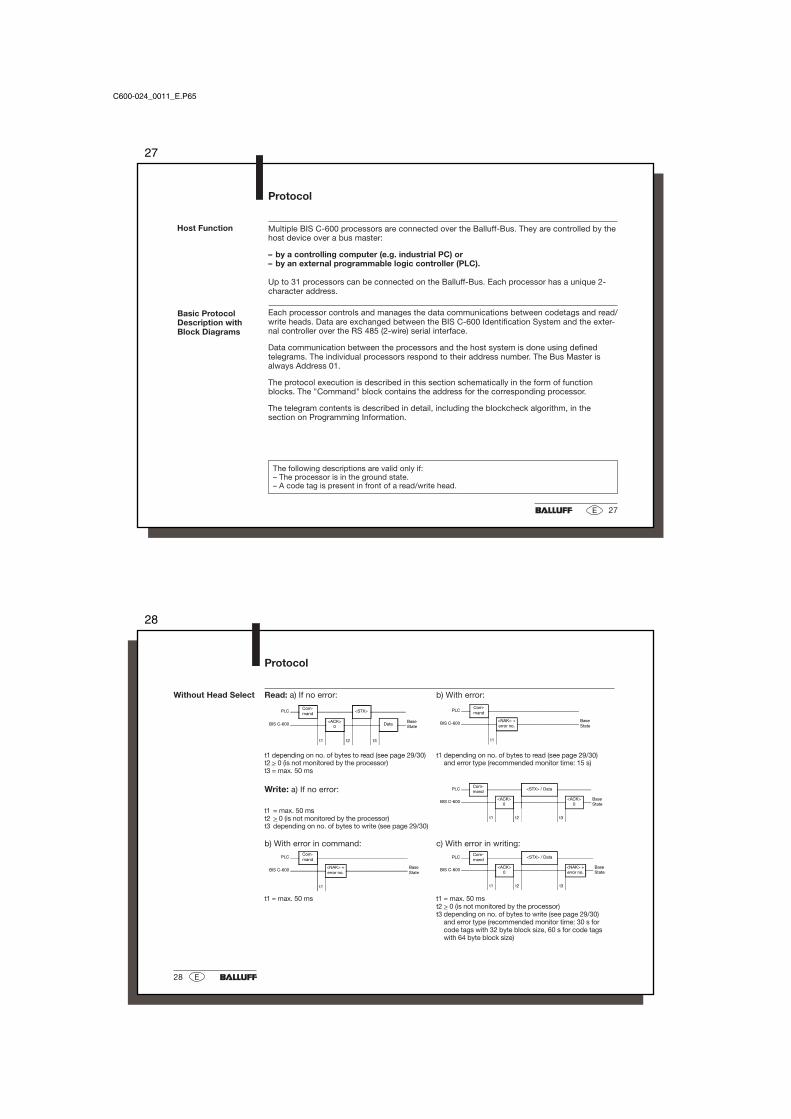
Multiple BIS C-600 processors are connected over the Balluff-Bus. They are controlled by thehost device over a bus master:
– by a controlling computer (e.g. industrial PC) or– by an external programmable logic controller (PLC).
Up to 31 processors can be connected on the Balluff-Bus. Each processor has a unique 2-character address.
Each processor controls and manages the data communications between codetags and read/write heads. Data are exchanged between the BIS C-600 Identification System and the exter-nal controller over the RS 485 (2-wire) serial interface.
Data communication between the processors and the host system is done using definedtelegrams. The individual processors respond to their address number. The Bus Master isalways Address 01.
The protocol execution is described in this section schematically in the form of functionblocks. The "Command" block contains the address for the corresponding processor.
The telegram contents is described in detail, including the blockcheck algorithm, in thesection on Programming Information.
Host Function
Protocol
The following descriptions are valid only if:– The processor is in the ground state.– A code tag is present in front of a read/write head.
Basic ProtocolDescription withBlock Diagrams
C600-024_0011_E.P65
28
28 E
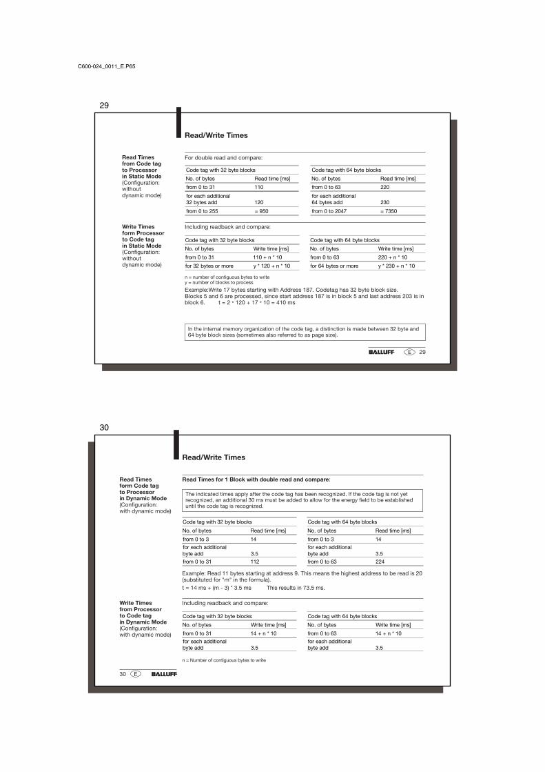
Without Head Select
Protocol
Read: a) If no error: b) With error:
PLCCom-mand
<STX>
BIS C-600<ACK>
0Data
BaseState
t1 t2 t3
PLCCom-mand
BIS C-600<NAK> +error no.
BaseState
t1
t1 depending on no. of bytes to read (see page 29/30) t1 depending on no. of bytes to read (see page 29/30)t2 > 0 (is not monitored by the processor) and error type (recommended monitor time: 15 s)t3 = max. 50 ms
Write: a) If no error: PLCCom-mand
<STX> / Data
BIS C-600<ACK>
0<ACK>
0BaseState
t1 t2 t3t1 = max. 50 mst2 > 0 (is not monitored by the processor)t3 depending on no. of bytes to write (see page 29/30)
b) With error in command: c) With error in writing:
PLCCom-mand
BIS C-600<NAK> +error no.
BaseState
t1
PLCCom-mand
<STX> / Data
BIS C-600<ACK>
0<NAK> +error no.
BaseState
t1 t2 t3
t1 = max. 50 ms t1 = max. 50 mst2 > 0 (is not monitored by the processor)t3 depending on no. of bytes to write (see page 29/30)
and error type (recommended monitor time: 30 s forcode tags with 32 byte block size, 60 s for code tagswith 64 byte block size)
In the internal memory organization of the code tag, a distinction is made between 32 byte and64 byte block sizes (sometimes also referred to as page size).
Read/Write Times
For double read and compare:
Code tag with 32 byte blocks Code tag with 64 byte blocks
No. of bytes Read time [ms] No. of bytes Read time [ms]
from 0 to 31 110 from 0 to 63 220
for each additional32 bytes add 120
for each additional64 bytes add 230
from 0 to 255 = 950 from 0 to 2047 = 7350
Including readback and compare:
Code tag with 32 byte blocks Code tag with 64 byte blocks
No. of bytes Write time [ms] No. of bytes Write time [ms]
from 0 to 31 110 + n * 10 from 0 to 63 220 + n * 10
for 32 bytes or more y * 120 + n * 10 for 64 bytes or more y * 230 + n * 10
n = number of contiguous bytes to writey = number of blocks to process
Example:Write 17 bytes starting with Address 187. Codetag has 32 byte block size.Blocks 5 and 6 are processed, since start address 187 is in block 5 and last address 203 is inblock 6. t = 2 * 120 + 17 * 10 = 410 ms
Read Times for 1 Block with double read and compare:
The indicated times apply after the code tag has been recognized. If the code tag is not yetrecognized, an additional 30 ms must be added to allow for the energy field to be establisheduntil the code tag is recognized.
n = Number of contiguous bytes to write
Read/Write Times
Example: Read 11 bytes starting at address 9. This means the highest address to be read is 20(substituted for "m" in the formula).t = 14 ms + (m - 3) * 3.5 ms This results in 73.5 ms.
Including readback and compare:Write Timesfrom Processorto Code tagin Dynamic Mode(Configuration:with dynamic mode)
Code tag with 32 byte blocks Code tag with 64 byte blocks
No. of bytes Read time [ms] No. of bytes Read time [ms]
from 0 to 3 14 from 0 to 3 14
for each additionalbyte add 3.5
for each additionalbyte add 3.5
from 0 to 31 112 from 0 to 63 224
Code tag with 32 byte blocks Code tag with 64 byte blocks
No. of bytes Write time [ms] No. of bytes Write time [ms]
from 0 to 31 14 + n * 10 from 0 to 63 14 + n * 10
for each additionalbyte add 3.5
for each additionalbyte add 3.5
31
31E
Now that the basic telegram sequence and the configuration have been shown in the preced-ing sections, what follows is information concerning addressing of the processors on theBalluff-Bus as well as the correct structure of a telegram.
There are specific telegrams for the various operations of the BIS C Identification System.Each begins with the control character <ENQ> (05 Hex) and the device address. Then followsthe command, which is associated with the telegram type:
'G' Assign an address to a processor
'U' Read out the processor address
'K' Delete the processor address
'L' Read the code tag with read/write select and block size
'P' Write to the code tag with read/write select and block size
'R' Read the code tag
'W' Write to the code tag
'H' Select the read/write head and block size with the variations
'?' Find the next code tag (one time)
'!' or find the next code tag (continuously)
'B' Process outputs
'Q' Restart the processor (acknowledge)
Please note:– The minimum wait time between two commands is 300 ms!
Intel-Hex Conversion To avoid the situation where the control character <ENQ> appears when transmitting dataand performing the blockcheck, the data and the BCC are Intel-Hex converted. Both Hexcharacters are thus sent as ASCII characters.'A' = 41Hex -> '4' (34Hex), '1' (31Hex)<ACK> = 06Hex -> '0' (30Hex), '6' (36Hex)'K' = 4BHex -> '4' (34Hex), 'B' (42Hex)
The processor looks for a character delay time of 65 ms. If this time is exceeded, the proces-sor goes into the ground state.
The BCC blockcheck is performed as an EXOR operation based on the serially transmittedbinary characters in the telegram block.
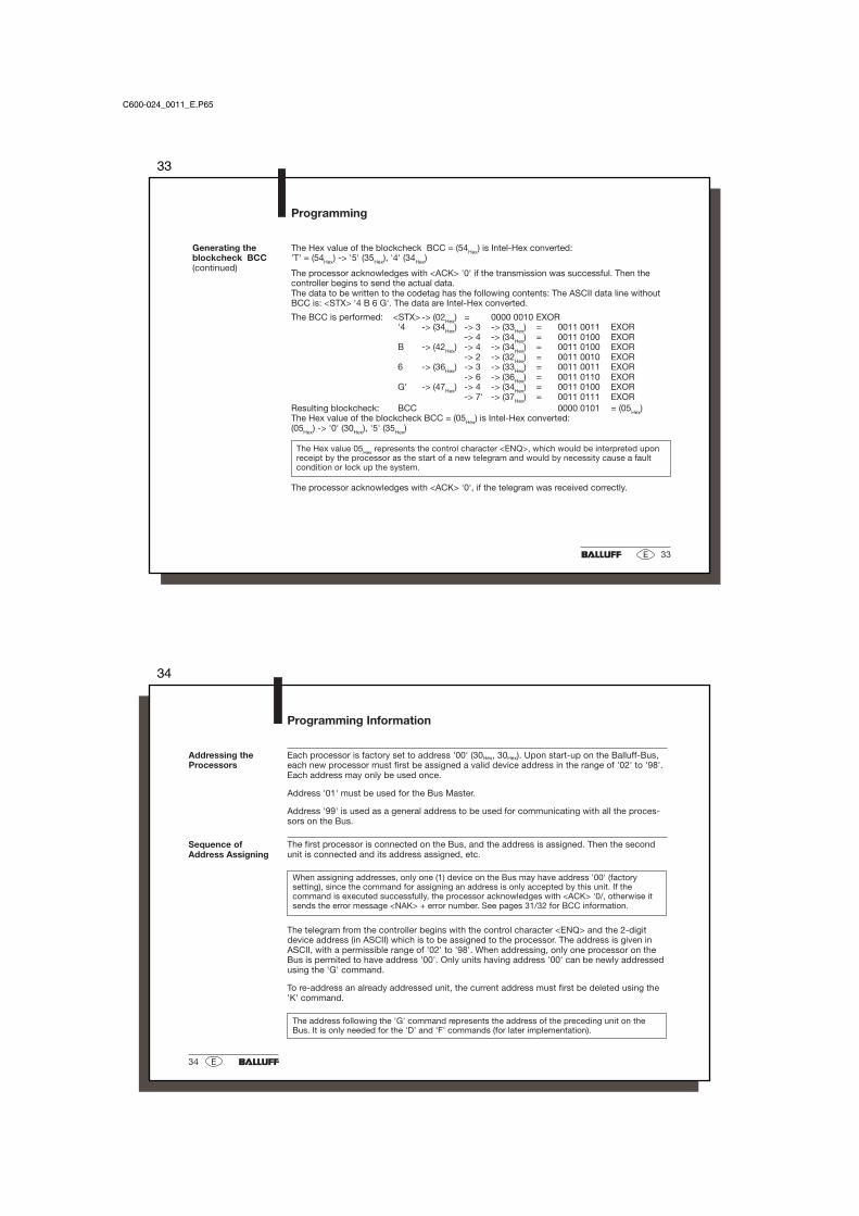
The Hex value of the blockcheck BCC = (54Hex) is Intel-Hex converted:'T' = (54Hex) -> '5' (35Hex), '4' (34Hex)
The processor acknowledges with <ACK> '0' if the transmission was successful. Then thecontroller begins to send the actual data.The data to be written to the codetag has the following contents: The ASCII data line withoutBCC is: <STX> '4 B 6 G'. The data are Intel-Hex converted.
-> 7' -> (37Hex) = 0011 0111 EXORResulting blockcheck: BCC 0000 0101 = (05Hex)The Hex value of the blockcheck BCC = (05Hex) is Intel-Hex converted:(05Hex) -> '0' (30Hex), '5' (35Hex)
The Hex value 05Hex represents the control character <ENQ>, which would be interpreted uponreceipt by the processor as the start of a new telegram and would by necessity cause a faultcondition or lock up the system.
The processor acknowledges with <ACK> '0', if the telegram was received correctly.
C600-024_0011_E.P65
34
34 E
Programming Information
Each processor is factory set to address '00' (30Hex, 30Hex). Upon start-up on the Balluff-Bus,each new processor must first be assigned a valid device address in the range of '02' to '98'.Each address may only be used once.
Address '01' must be used for the Bus Master.
Address '99' is used as a general address to be used for communicating with all the proces-sors on the Bus.
The first processor is connected on the Bus, and the address is assigned. Then the secondunit is connected and its address assigned, etc.
When assigning addresses, only one (1) device on the Bus may have address '00' (factorysetting), since the command for assigning an address is only accepted by this unit. If thecommand is executed successfully, the processor acknowledges with <ACK> '0/, otherwise itsends the error message <NAK> + error number. See pages 31/32 for BCC information.
The telegram from the controller begins with the control character <ENQ> and the 2-digitdevice address (in ASCII) which is to be assigned to the processor. The address is given inASCII, with a permissible range of '02' to '98'. When addressing, only one processor on theBus is permited to have address '00'. Only units having address '00' can be newly addressedusing the 'G' command.
To re-address an already addressed unit, the current address must first be deleted using the'K' command.
The address following the 'G' command represents the address of the preceding unit on theBus. It is only needed for the 'D' and 'F' commands (for later implementation).
Addressing theProcessors
Sequence ofAddress Assigning
35
35E
Programming Information
Example:Addressingthe Slave Units
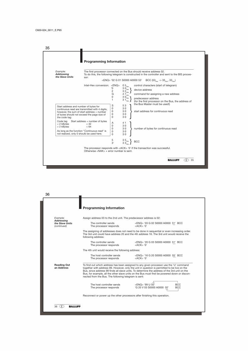
The first processor connected on the Bus should receive address 02.To do this, the following telegram is constructed in the controller and sent to the BIS proces-sor:
Intel-Hex conversion: <ENQ> 0 5Hex control characters (start of telegram)'0 3 0Hex device address 2 3 2Hex G 4 7Hex command for assigning a new address 0 3 0Hex predecessor address 1 3 1Hex (for the first processor on the Bus, the address of
the Bus Master must be used!) S 5 3 0 3 0 0 3 0 start address for continuous read 0 3 0 0 3 0
A 4 1 0 3 0 0 3 0 number of bytes for continuous read 0 3 0 0 3 0
5 3 5Hex BCC 3' 3 3Hex
The processor responds with <ACK> '0' if the transaction was successful.Otherwise <NAK> + error number is sent.
Start address and number of bytes forcontinuous read are transmitted with 4 digits,however, the sum of start address + numberof bytes should not exceed the page size ofthe code tag:
Code tag Start address + number of bytes< 2 kBytes < 32> 2 kBytes < 64
As long as the function "Continuous read" isnot realized, only 0 shoulb be used here.
C600-024_0011_E.P65
36
36 E
Assign address 03 to the 2nd unit. The predecessor address is 02:
The controller sends <ENQ> '03 G 02 S0000 A0000 51' BCCThe processor responds <ACK> '0'
The assigning of addresses does not need to be done in sequential or even increasing order.The 3rd unit could have address 20 and the 4th address 16. The 3rd unit would receive thefollowing address:
The controller sends <ENQ> '20 G 03 S0000 A0000 51' BCCThe processor responds <ACK> '0'
The 4th unit would receive the following address:
The host controller sends <ENQ> '16 G 20 S0000 A0000 55' BCCThe processor responds <ACK> '0'
To find out which address has been assigned to any given processor use the 'U' commandtogether with address 99. However, only the unit in question is permitted to be live on theBus, since address 99 finds all slave units. To determine the address of the 3rd unit on theBus, for example, all the other slave units on the Bus must first be powered down or discon-nected from the Bus. The following telegram is sent:
The host controller sends <ENQ> '99 U 50' BCCThe processor responds 'G 20 V 03 S0000 A0000 02' BCC
Reconnect or power up the other processors after finishing this operation.
Reading Outan Address
Example:Addressingthe Slave Units(continued)
Programming Information
37
37E
Delete (change)an Address
Programming Information
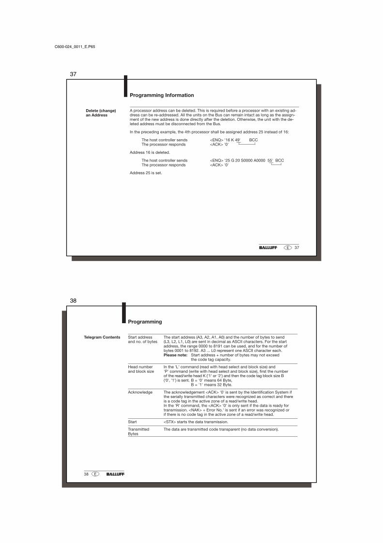
A processor address can be deleted. This is required before a processor with an existing ad-dress can be re-addressed. All the units on the Bus can remain intact as long as the assign-ment of the new address is done directly after the deletion. Otherwise, the unit with the de-leted address must be disconnected from the Bus.
In the preceding example, the 4th processor shall be assigned address 25 instead of 16:
The host controller sends <ENQ> '16 K 49' BCCThe processor responds <ACK> '0'
Address 16 is deleted.
The host controller sends <ENQ> '25 G 20 S0000 A0000 55' BCCThe processor responds <ACK> '0'
Address 25 is set.
C600-024_0011_E.P65
38
38 E
Telegram Contents Start address The start address (A3, A2, A1, A0) and the number of bytes to sendand no. of bytes (L3, L2, L1, L0) are sent in decimal as ASCII characters. For the start
address, the range 0000 to 8191 can be used, and for the number ofbytes 0001 to 8192. A3 ... L0 represent one ASCII character each.Please note: Start address + number of bytes may not exceed
the code tag capacity.
Head number In the 'L' command (read with head select and block size) andand block size 'P' command (write with head select and block size), first the number
of the read/write head K ('1' or '2') and then the code tag block size B('0', '1') is sent. B = '0' means 64 Byte,
B = '1' means 32 Byte.
Acknowledge The acknowledgement <ACK> '0' is sent by the Identification System ifthe serially transmitted characters were recognized as correct and thereis a code tag in the active zone of a read/write head.In the 'R' command, the <ACK> '0' is only sent if the data is ready fortransmission. <NAK> + Error No.' is sent if an error was recognized orif there is no code tag in the active zone of a read/write head.
Start <STX> starts the data transmission.
Transmitted The data are transmitted code transparent (no data conversion).Bytes
Programming
39
39E
Values inside apostrophes represent the respective character(s) in ASCII code.
Programming
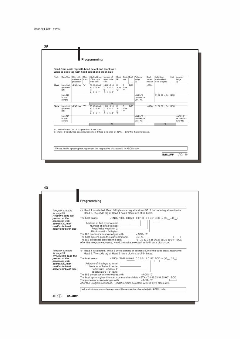
Read from code tag with head select and block sizeWrite to code tag with head select and block size
Task Data Flow Start withaddress ofprocessor
Com-mand
Start addressof first byteto be sent
Number ofbytes to besent
HeadNo.
Blocksize
End Acknow-ledge2)
Starttrans-mission
Data (fromstart address+ no. of bytes)
End Acknow-ledge2)
Read from hostsystem toBIS
<ENQ>'xx 'L' A3 A2 A1 A0'0 0 0 0'to'8 1 9 1'
L3 L2 L1 L0'0 0 0 1'to'8 1 9 2'
K'1' or'2'
B'0' or'1'
BCC <STX>
from BISto hostsystem
<ACK>'0'or <NAK> +Error-No.
D1 D2 D3 ... Dn BCC
1)
Write from hostsystem toBIS
<ENQ>'xx 'P' A3 A2 A1 A0'0 0 0 0'to'8 1 9 1'
L3 L2 L1 L0'0 0 0 1'to'8 1 9 2'
K'1'or'2'
B'0' or'1'
BCC <STX> D1 D2 D3 ... Dn BCC
from BISto hostsystem
<ACK>'0'or <NAK> +Error-No.
<ACK>'0'or <NAK> +Error-No.
1) 1)
1) The command 'Quit' is not permitted at this point.2) <ACK> '0' is returned as acknowledgement if there is no error, or <NAK> + Error No. if an error occurs.
C600-024_0011_E.P65
40
40 E
-> Head 1 is selected. Read 10 bytes starting at address 50 of the code tag at read/writeHead 2. The code tag at Head 4 has a block size of 64 bytes.
Address of first byte to readNumber of bytes to read
Read/write Head No. 2Block size 0 = 64 bytes
The BIS processor acknowledges with <ACK> '0'The host system gives the start command <STX>The BIS processor provides the data '31 32 33 34 35 36 37 38 39 30 01' BCCAfter the telegram sequence, Head 2 remains selected, with 64 byte block size.
-> Head 1 is selected. Write 5 bytes starting at address 500 of the code tag at read/writeHead 2. The code tag at Head 2 has a block size of 64 bytes.
Address of first byte to writeNumber of bytes to write
Read/write Head No. 2Block size 0 = 64 Byte
The BIS processor acknowledges with <ACK> '0'The host system gives the start command and data <STX> '31 32 33 34 35 00' BCCThe processor acknowledges with <ACK> '0'After the telegram sequence, Head 2 remains selected, with 64 byte block size.
Values inside apostrophes represent the respective character(s) in ASCII code.
Programming
Telegram examplefor page 39:Read the code tagpresent at theprocessor withaddress 20, withread/write headselect and block size
Telegram examplefor page 39:Write to the code tagpresent at theprocessor withaddress 20, withread/write headselect and block size
41
41E
Programming
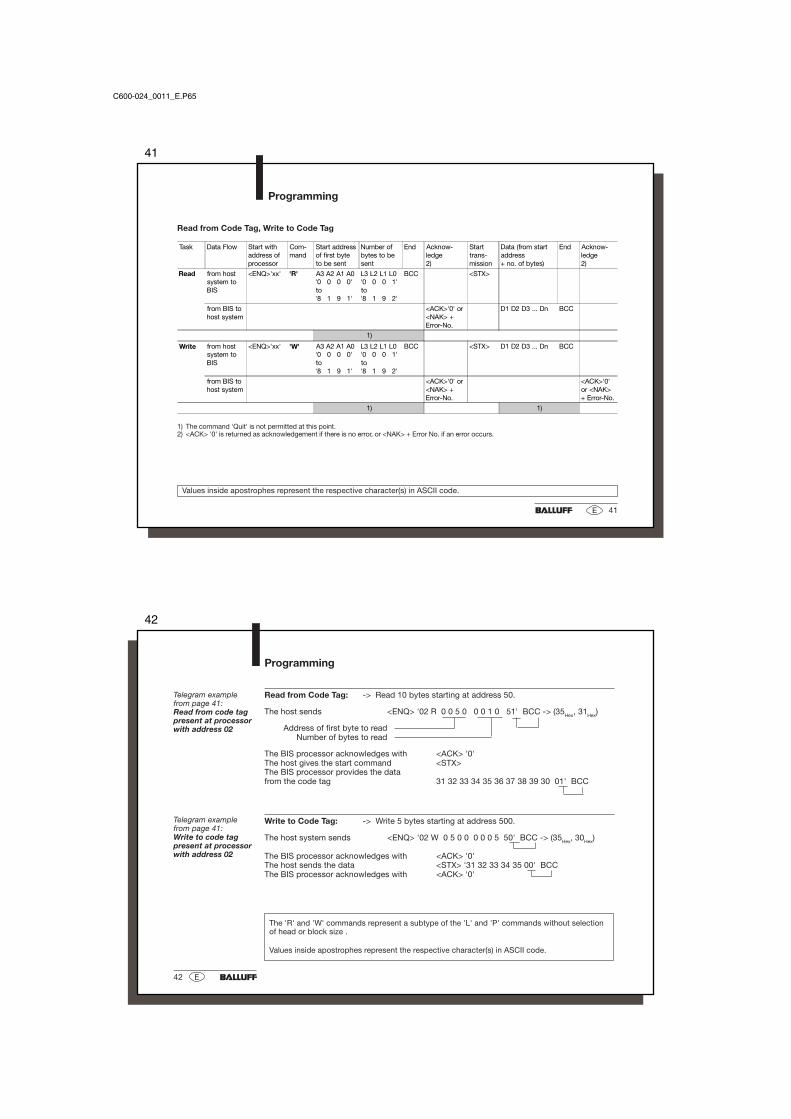
Read from Code Tag, Write to Code Tag
Values inside apostrophes represent the respective character(s) in ASCII code.
1) The command 'Quit' is not permitted at this point.2) <ACK> '0' is returned as acknowledgement if there is no error, or <NAK> + Error No. if an error occurs.
Task Data Flow Start withaddress ofprocessor
Com-mand
Start addressof first byteto be sent
Number ofbytes to besent
End Acknow-ledge2)
Starttrans-mission
Data (from startaddress+ no. of bytes)
End Acknow-ledge2)
Read from hostsystem toBIS
<ENQ>'xx' 'R' A3 A2 A1 A0'0 0 0 0'to'8 1 9 1'
L3 L2 L1 L0'0 0 0 1'to'8 1 9 2'
BCC <STX>
from BIS tohost system
<ACK>'0' or<NAK> +Error-No.
D1 D2 D3 ... Dn BCC
1)
Write from hostsystem toBIS
<ENQ>'xx' 'W' A3 A2 A1 A0'0 0 0 0'to'8 1 9 1'
L3 L2 L1 L0'0 0 0 1'to'8 1 9 2'
BCC <STX> D1 D2 D3 ... Dn BCC
from BIS tohost system
<ACK>'0' or<NAK> +Error-No.
<ACK>'0'or <NAK>+ Error-No.
1) 1)
C600-024_0011_E.P65
42
42 E
Programming
The 'R' and 'W' commands represent a subtype of the 'L' and 'P' commands without selectionof head or block size .
Values inside apostrophes represent the respective character(s) in ASCII code.
Telegram examplefrom page 41:Read from code tagpresent at processorwith address 02
Telegram examplefrom page 41:Write to code tagpresent at processorwith address 02
Read from Code Tag: -> Read 10 bytes starting at address 50.
The host sends <ENQ> '02 R 0 0 5 0 0 0 1 0 51' BCC -> (35Hex, 31Hex)
Address of first byte to readNumber of bytes to read
The BIS processor acknowledges with <ACK> '0'The host gives the start command <STX>The BIS processor provides the datafrom the code tag 31 32 33 34 35 36 37 38 39 30 01' BCC
Write to Code Tag: -> Write 5 bytes starting at address 500.
The host system sends <ENQ> '02 W 0 5 0 0 0 0 0 5 50' BCC -> (35Hex, 30Hex)
The BIS processor acknowledges with <ACK> '0'The host sends the data <STX> '31 32 33 34 35 00' BCCThe BIS processor acknowledges with <ACK> '0'
43
43E
Selecting aRead/Write Head(two heads have to beconnected to theprocessor)
Programming
The 'H1' command selects Read/Write Head 1, 'H2' Read/Write Head 2, and 'HT' (Head Twin)both Read/Write Heads.If both heads are selected, please note:1. Only one code tag is allowed to be in the active zone of a read/write head at a time.2. The read or write time increases by ca. 40 ms - regardless of the data amount to be read or
written. (This does not apply to the code tag recognition).3. The positive acknowledgement for a read or write action is no longer <ACK> '0' but rather
<ACK> '1' or <ACK> '2', depending on at which read/write head there is a code tag to beread from or written to.
1) The commands 'Status' and/or "Quit' are not permitted at this point.2) <ACK> '0' is returned as acknowledgement if there is no error, or <NAK> + Error No. if an error occurs.
Values inside apostrophes represent the respective character(s) in ASCII code.
-> Switch to Head 1.
The host sends <ENQ> '33 H 1 7C' BCC -> (37Hex, 43Hex)The BIS processor acknowledges with <ACK> '0'
Telegram example:Selecting aRead/Write HeadTelegram with blockcheck (BCC)
Task Data Flow Start withaddress ofprocessor
Com-mand
Head number End Acknowledge2)
SelectRead/WriteHead
from host systemto BIS
<ENQ>'xx 'H' '1', '2' or 'T' BCC
from BIS to hostsystem
<ACK> '0', '1' or '2'resp. <NAK>+Error-No.
1)
C600-024_0011_E.P65
44
44 E
Find Next Code Tag(one time)
Programming
Values inside apostrophes represent the respective character(s) in ASCII code.
The following telegram is used to find the next code tag. The next following read/write head isselected and checked to see if a code tag is in front of this read/write head. If yes, the first 4bytes of the code tag are read. The telegram reply then contains the corresponding number ofthe read/write head and the four bytes read. If no tag is found, the original read/write head isreselected and checked. If no code tag is found here, then the telegram reply is: 'H ? 0000 77'.'H ?' recognizes any code tag, regardless of the preset block size, assuming that read/writehead and code tag are compatible.
1) The commands 'Status' and/or "Quit' are not permitted at this point.
-> Head 1 is selected. Only read/write head 2 has a code tag in front of it, whose first fourbytes are 9876.
The host sends <ENQ> '33 H ? 72' BCC -> (37Hex, 32Hex)
The BIS processor acknowledges with <ACK> '0'and sends the data 'H 2 39 38 37 36 7A' BCC
Telegram example:Find next code tag(one time) at deviceaddress 33
Task Data Flow Start withaddress ofprocessor
Com-mand
Des. End Acknow-ledge
Reply Headnumber
Data fromcode tag
End
Find nextcode tag(one time)
from hostsystem to BIS
<ENQ>'xx 'H' '?' BCC
from BIS tohost system
<ACK>'0' 'H' '1', '2' or'?'
D1 D2 D3 D4 BCC
1)
45
45E
Find Next Code Tag(continuous)
Programming
The following telegram is used to find the next code tag. The next following read/write head isselected and checked to see if a code tag is in front of this read/write head. If yes, the firstfour bytes of the code tag are read. The telegram reply then contains the corresponding num-ber of the read/write head and the four bytes read. If no tag is found, the original read/writehead is reselected and checked. This procedure is repeated until a code tag is found.
H !' recognizes any code tag, regardless of the preset block size, assuming that read/writehead and code tag are compatible.
1) The command 'Quit' is not permitted at this point.
-> Read/write head 2 has a code tag in front of it whose first four bytes are 9876.
The host sends <ENQ> '33 H ! 6C' BCC -> (36Hex, 43Hex)
The BIS processor acknowledges with <ACK> '0'and sends the data 'H 2 39 38 37 36 7A' BCC
Values inside apostrophes represent the respective character(s) in ASCII code.
Task Data Flow Start withaddress ofprocessor
Com-mand
Desi-gnator
End Acknow-ledge
Reply Headnumber
Data fromcode tag
End
Find nextcode tag(contin.)
from hostsystem to BIS
<ENQ>'xx 'H' '!' BCC
from BIS tohost system
<ACK>'0' 'H' '1' or '2' D1 D2 D3 D4 BCC
1)
Telegram example:Find next code tag(continuous) atdevice address 33
C600-024_0011_E.P65
46
46 E
Configuring theOutputs
Programming
A telegram can be sent to configure or cancel the four outputs.
1) The command 'Quit' is not permitted at this point.
Designator meaning: Output No. 0 1 2 3 all outputs
Values inside apostrophes represent the respective character(s) in ASCII code.
The host sends <ENQ> '22 B 21 44' BCC (34Hex, 34Hex)The BIS processor acknowledges with <ACK> '0'
After the telegram is completed, output 2 is set.
Telegram example:Set output 2at device address 22
Task Data Flow Start withaddress ofprocessor
Com-mand
Designator Termi-nator
Acknow-ledge
Processoutputs(set or cancel)
from host system toBIS
<ENQ>'xx 'B' '00' bis 'A1'(see below)
BCC
from BIS to hostsystem
<ACK>'0'
1)
47
47E
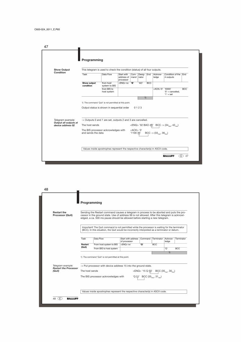
Show OutputCondition
Programming
This telegram is used to check the condition (status) of all four outputs.
1) The command 'Quit' is not permitted at this point.
Output status is shown in sequential order 0 1 2 3
Values inside apostrophes represent the respective character(s) in ASCII code.
-> Outputs 0 and 1 are set, outputs 2 and 3 are cancelled.
The host sends <ENQ> '02 BAO 4B' BCC -> (34Hex, 42Hex)
The BIS processor acknowledges with <ACK> '0'and sends the data '1100 36' BCC -> (33Hex, 36Hex)
Telegram example:Output all outputs atdevice address 02
Task Data Flow Start withaddress ofprocessor
Com-mand
Desig-nator
End Acknow-ledge
Condition of the4 outputs
End
Show outputcondition
from hostsystem to BIS
<ENQ>'xx 'B' 'AO' BCC
from BIS tohost system
<ACK>'0' 'XXXX''0' = cancelled,'1' = set
BCC
1)
C600-024_0011_E.P65
48
48 E
Restart theProcessor (Quit)
Programming
Sending the Restart command causes a telegram in process to be aborted and puts the pro-cessor in the ground state. Use of address 99 is not allowed. After this telegram is acknowl-edged, a ca. 500 ms pause should be allowed before starting a new telegram.
Important! The Quit command is not permitted while the processor is waiting for the terminator(BCC). In this situation, the Quit would be incorrectly interpreted as a terminator or datum.
1) The command 'Quit' is not permitted at this point.
-> Put processor with device address 15 into the ground state.
The host sends <ENQ> '15 Q 50' BCC (35Hex, 30Hex)
The BIS processor acknowledges with 'Q 51' BCC (35Hex, 31Hex)
Values inside apostrophes represent the respective character(s) in ASCII code.
Telegram example:Restart the Processor(Quit)
Task Data Flow Start with addressof processor
Command Terminator Acknow-ledge
Terminator
Restart(Quit)
From host system to BIS <ENQ>'xx' 'Q' BCC
From BIS to host system 'Q' BCC
1)
49
49E
Error Numbers
Error Numbers
The BIS C-600 always outputs an error number. The meaning of these error numbers is indi-cated in the following table.
Error Description EffectNo.
1 No code tag present Telegram aborted,processor goes into ground state.
2 Read error Read telegram aborted,processor goes into ground state.
3 Read aborted, since the Processor goes into ground state.code tag was removed
4 Write error Write telegram aborted,processor goes into ground state.CAUTION: Some new data may still havebeen written to the code tag!
5 Writing aborted,since the Processor goes into ground state.code tag was removed CAUTION: Some new data may still have
been written to the code tag!
6 Interface error Processor goes into ground state.(parity or stop bit error)
7 Telegram format error Processor goes into ground state.Possible format errors:- Command is not 'R', 'W', 'L', 'P', 'H', 'Q' or 'S'.- Start address or number of bytes exceedpermissible range
C600-024_0011_E.P65
50
50 E
8 BCC error, the trans- Telegram is aborted,mitted BCC is wrong processor goes into ground state.
9 Cable break, Telegram is aborted,Codetag Present processor goes into ground state.LED flashes Cable break from read/write head or cable not
connected.If both read/write heads were selected using 'HT',one head may not be connected.If both read/write heads are selected, the cablebreak message only comes if there is no code tag infront of the connected, functional head.
A New command not possible, After error message the read command is stopped,since a read command is internally, but not acknowledged.already in process Processor goes into ground state.
B New command not possible, After error message the write command is stopped,since a write command is internally, but not acknowledged.already in process. Processor goes into ground state.
CAUTION: If errors occur after new attempts to writeto the code tag, no further error messages will begiven.
C New command not possible, After the error message, no positive acknowledgesince a head select is is given, even thought the head select wasalready in process. successful. Processor goes into ground state.
Error Numbers(continued)
Error Numbers
51
51E
LED Display:System ReadyCodetag PresentCodetag Operating
The BIS C-600 Processor uses three LED's on the front panel to indicate the most importantoperating conditions.
Condition LED Meaning
System on (green) Supply voltage OK; no hardware errorReady off Supply voltage or hardware not OK
Codetag on (yellow) Code tag ready to read or write. (If a read/write error occursPresent during a read/write operation, System Ready LED goes out,
if the protocol variant "without error number" is used!)flashes Read/write head cable break or not connected.
If both read/write heads were selected using 'HT', one head maynot be connected.
If both read/write heads are selected, the cable break messageonly comes if there is no code tag in front of the connected,functional head.
off No code tag in active zone of read/write head
Codetag on (yellow) Command being processedOperating off No command in process
If all three LED's flash on and off synchronously, the processor needs to be returned to the factory for repair.
Interface
C600-024_0011_E.P65
52
52 E
Interface
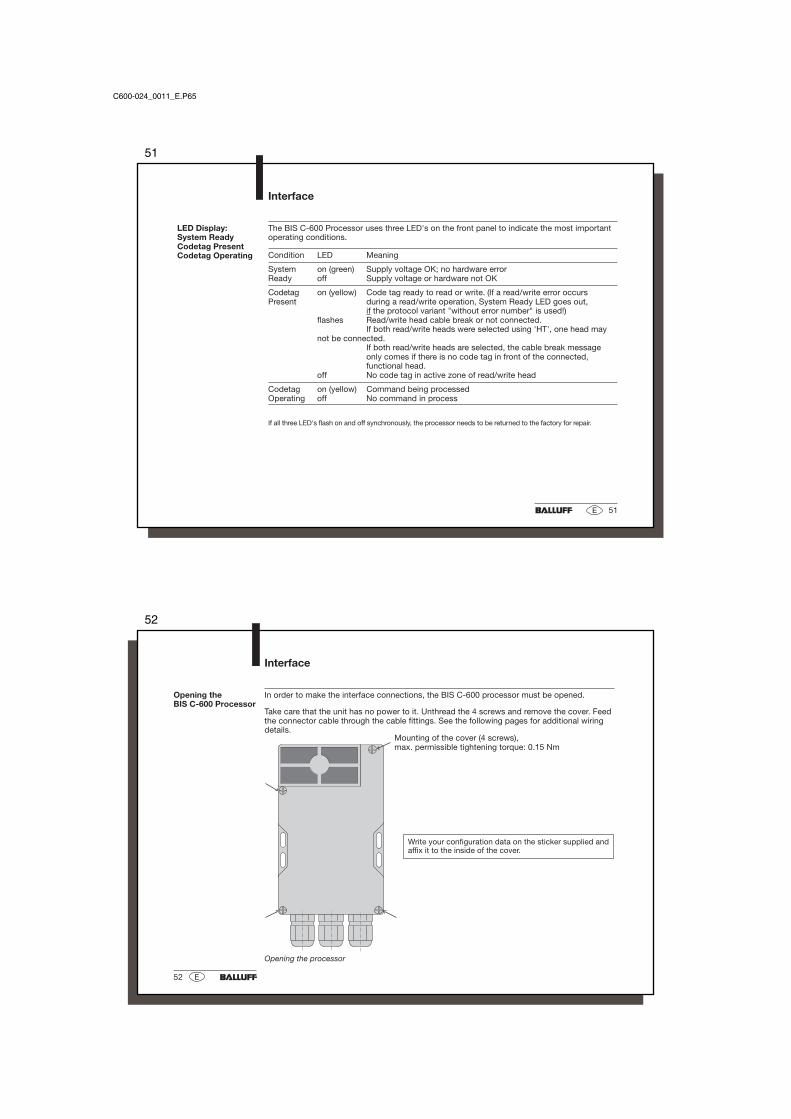
In order to make the interface connections, the BIS C-600 processor must be opened.
Take care that the unit has no power to it. Unthread the 4 screws and remove the cover. Feedthe connector cable through the cable fittings. See the following pages for additional wiringdetails.
Opening theBIS C-600 Processor
Opening the processor
Write your configuration data on the sticker supplied andaffix it to the inside of the cover.
Mounting of the cover (4 screws),max. permissible tightening torque: 0.15 Nm
53
53E
Connections to theBIS C-600 Processor
Interface
13 12 11 10 9 8 7 6
+ VS - VS 1 2 3 4 +IN -IN
OUTPUT INPUT
R = ReceiveT = Transmit
19 18 17 16 15 14
+ VS - VS AH EH
POWER HEAD #2
5 4 3 2 1
COMR/T(A)
R/T(B)
RS 485 (2-Draht)
5 4 3 2 1
COM T (A) T (B) R (A) R (B)
RS 422 (4-Draht)
Connections to the Terminal blockProcessor opened
Interface connection
I/O
Power, 2nd read/write head
Terminalblock
C600-024_0011_E.P65
54
54 E
Interface
The BIS C-600-024...04 uses a serial interface for communication with the host system (PLCor PC). Depending on how it is configured, the interface can be used asRS 422 (4-wire) or RS 485 (2-wire) preferably.
Terminal connectionsfor an RS 422 interface(4-wire)
Terminal connectionsfor an RS 485 interface(2-wire)
RS 422: Shunt-connector X 4/1 RS 485: Shunt-connector X 4/2must be plugged in! must be plugged in!
Jumper connector fortermination resistor
Termination Jumpers forresistor X 4/3 X 4/4
passive - -
active plugged plugged
only if required!only if required!
Connection cableand Interface forRS 422 / RS 485
55
55E
Assembly of theBIS C-600 Processorand Read/WriteHead or Adapter
AssemblyProcessor / Head
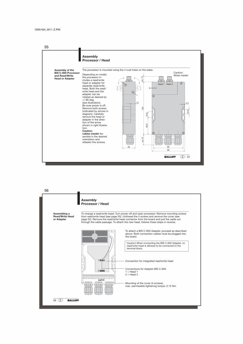
The processor is mounted using the 4 oval holes on the sides.
Depending on model,the processor in-cludes a read/writehead or adapter forseparate read/writehead. Both the read/write head and theadapter can berotated as desired by+/-90 deg.(see illustration).Be sure power is off.Remove both screws(indicated by arrows indiagram). Carefullyremove the head oradapter in the direc-tion of the arrowshown in right illustra-tion.Caution:cables inside! As-semble in the desiredorientation andrefasten the screws.
Caution:Wires inside!
C600-024_0011_E.P65
56
56 E
AssemblyProcessor / Head
To change a read/write head: Turn power off and open processor. Remove mounting screwsfrom read/write head (see page 55). Unthread the 4 screws and remove the cover (seepage 52). Remove the read/write head connector from the board and pull the cable outthrough the cable passage. To attach the new head, follows these steps in reverse.
To attach a BIS C-650 Adapter, proceed as describedabove. Both connection cables must be plugged intothe board.
Caution! When connecting the BIS C-650 Adapter, noread/write head is allowed to be connected to theterminal block.
Connection for integrated read/write head
Connections for Adapter BIS C-6501 = Head 12 = Head 2
Mounting of the cover (4 screws),max. permissible tightening torque: 0.15 Nm
Assembling aRead/Write Heador Adapter
57
57E
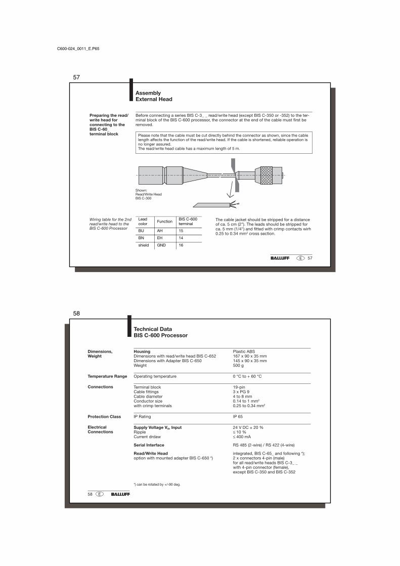
Before connecting a series BIS C-3_ _ read/write head (except BIS C-350 or -352) to the ter-minal block of the BIS C-600 processor, the connector at the end of the cable must first beremoved.
Please note that the cable must be cut directly behind the connector as shown, since the cablelength affects the function of the read/write head. If the cable is shortened, reliable operation isno longer assured.The read/write head cable has a maximum length of 5 m.
Preparing the read/write head forconnecting to theBIS C-60_terminal block
Leadcolor
FunctionBIS C-600terminal
BU AH 15
BN EH 14
shield GND 16
Wiring table for the 2ndread/write head to theBIS C-600 Processor
Shown:Read/Write HeadBIS C-300
The cable jacket should be stripped for a distanceof ca. 5 cm (2"). The leads should be stripped forca. 5 mm (1/4") and fitted with crimp contacts wirh0.25 to 0.34 mm2 cross section.
AssemblyExternal Head
C600-024_0011_E.P65
58
58 E
Dimensions,Weight
Housing Plastic ABSDimensions with read/write head BIS C-652 167 x 90 x 35 mmDimensions with Adapter BIS C-650 145 x 90 x 35 mmWeight 500 g
Operating temperature 0 °C to + 60 °C
Terminal block 19-pinCable fittings 3 x PG 9Cable diameter 4 to 8 mmConductor size 0.14 to 1 mm2
with crimp terminals 0.25 to 0.34 mm2
IP Rating IP 65
Supply Voltage VS, Input 24 V DC ± 20 %Ripple ≤ 10 %Current drdaw ≤ 400 mA
Serial Interface RS 485 (2-wire) / RS 422 (4-wire)
Read/Write Head integrated, BIS C-65_ and following *);option with mounted adapter BIS C-650 *) 2 x connectors 4-pin (male)
for all read/write heads BIS C-3_ _with 4-pin connector (female),except BIS C-350 and BIS C-352
Technical DataBIS C-600 Processor
*) can be rotated by +/-90 deg.
Temperature Range
Connections
Protection Class
ElectricalConnections
59
59E
ElectricalConnections
Technical DataBIS C-600 Processor
Digital Input (+IN, –IN) Optocoupler isolatedControl voltage active 4 V to 40 VControl voltage inactive 1.5 V to –40 VInput current at 24 V 11 mATypical delay time 5 ms
Control Outputs (01 to 04) Optocoupler isolatedOutput current max. 20 mAVoltage drop at 20 mA ca. 2.5 VOutput resistance RO 10 kΩ to VS
Logic PNP (sourcing)Supply voltage, Output VS 24 V DC ± 20 %Ripple ≤ 10 %
System Ready LED greenCodetag Present LED yellowCodetag Operating LED yellow
Function Displays
With the CE Mark we affirm that our products are in accordance with therequirements of the EU (European Union) Guideline89/336/EEC (EMC Guideline)
and the EMC Law. It has been verified in our EMC Laboratory, which is accredited by theDATech for Testing of Electromagnetic Compatibility, that Balluff products meet the EMCrequirements of the Harmonized Standard
EN 50081-2 (Emission), EN 50082-2 (Noise Immunity)
C600-024_0011_E.P65
60
60 E
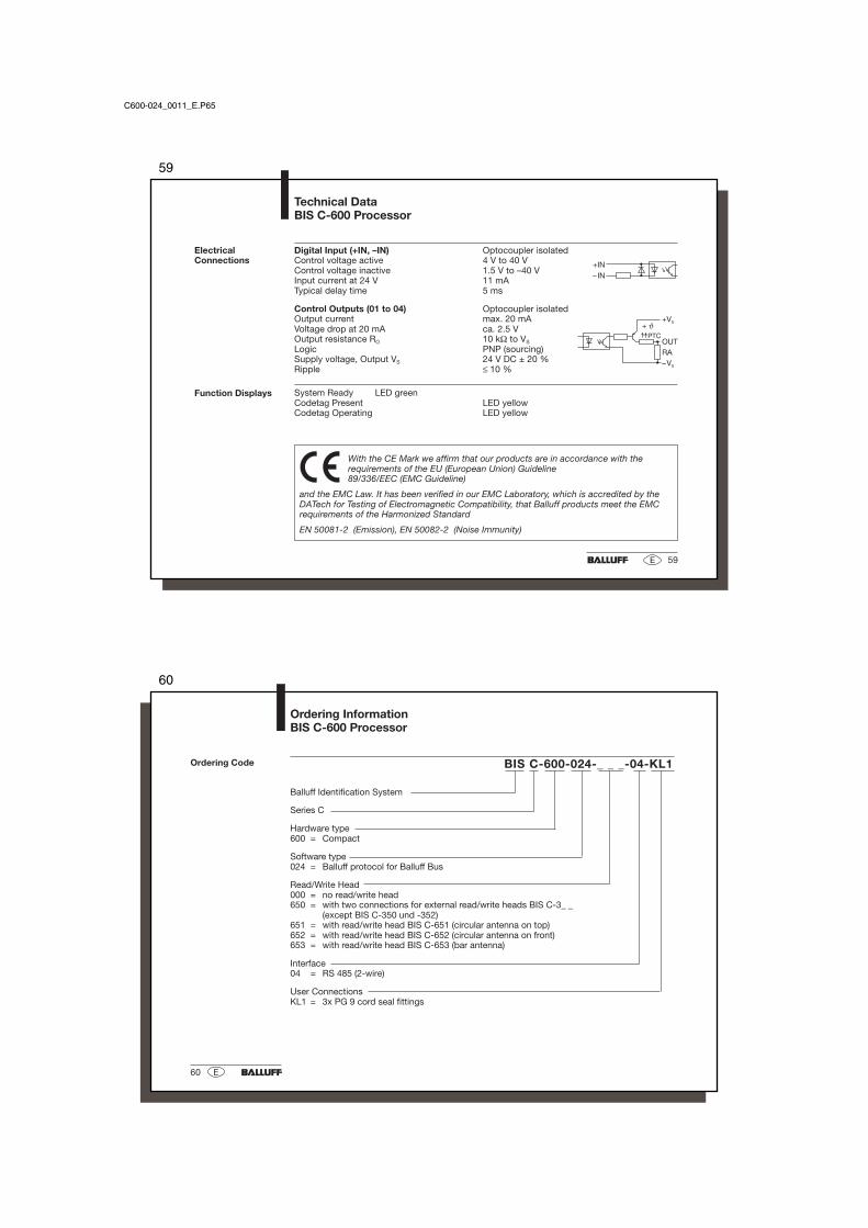
BIS C-600-024-_ _ _-04-KL1
Ordering InformationBIS C-600 Processor
Ordering Code
Balluff Identification System
Series C
Hardware type600 = Compact
Software type024 = Balluff protocol for Balluff Bus
Read/Write Head000 = no read/write head650 = with two connections for external read/write heads BIS C-3_ _
(except BIS C-350 und -352)651 = with read/write head BIS C-651 (circular antenna on top)652 = with read/write head BIS C-652 (circular antenna on front)653 = with read/write head BIS C-653 (bar antenna)
Interface04 = RS 485 (2-wire)
User ConnectionsKL1 = 3x PG 9 cord seal fittings
61
61E
Appendix, ASCII Table
Deci-mal Hex Control
Code ASCII Deci-mal Hex Control
Code ASCII Deci-mal Hex ASCII Deci-
mal Hex ASCII Deci-mal Hex ASCII Deci-
mal Hex ASCII
0 00 Ctrl @ NUL 22 16 Ctrl V SYN 44 2C , 65 41 A 86 56 V 107 6B k
1 01 Ctrl A SOH 23 17 Ctrl W ETB 45 2D - 66 42 B 87 57 W 108 6C l
2 02 Ctrl B STX 24 18 Ctrl X CAN 46 2E . 67 43 C 88 58 X 109 6D m
3 03 Ctrl C ETX 25 19 Ctrl Y EM 47 2F / 68 44 D 89 59 Y 110 6E n
4 04 Ctrl D EOT 26 1A Ctrl Z SUB 48 30 0 69 45 E 90 5A Z 111 6F o
5 05 Ctrl E ENQ 27 1B Ctrl [ ESC 49 31 1 70 46 F 91 5B [ 112 70 p