October 1993 12-900261-000 Supplemental Instructions for Installing the Electronic Pinsetter Trigger/Control System onto Model A Pinsetters BRUNSWICK SERVICE PARTS AND SUPPLIES • MUSKEGON, MI 49443
Transcript
Electronic Pinsetter Trigger/Control System-Model "A" Supplement
October 1993 12-900261-000
Supplemental Instructionsfor Installing the
Electronic PinsetterTrigger/Control System
ontoModel A Pinsetters
BRUNSWICK SERVICE PARTS AND SUPPLIES • MUSKEGON, MI 49443
ELECTRONIC PINSETTER TRIGGER/CONTROL SYSTEM ONTO MODEL A PINSETTERS
Reorder Part No. 12-900261-000
Confidential material under license.DO NOT reproduce or disclose.
Brunswick Bowling and Billiards CorporationElectronics - Publications525 West Laketon AvenueP.O. Box 329Muskegon, MI 49443-0329
Electronic Pinsetter Trigger/Control System-Model "A" Supplement
Contents
Introduction ............................................................................................................................1Preparation .................................................................................................................... .......1Tools Required ...................................................................................................................... 2Removal of Existing Cycle Relay ............................................................................................ 2Installation of New Control Board ........................................................................................... 5Installation of Rake-Up/Trigger Switch ....................................................................................8Modification of Low Voltage Terminal Strip ..........................................................................10Wire Connection of Control Board .......................................................................................15Mechanical Modifications ....................................................................................................17
This supplemental package provides the additional instructions andparts needed to install the part no. 12-862900-400 Electronic Trigger/Control System onto Model "A" pinsetters - i.e. pinsetters that do NOThave an A-2 style pit cushion and rake trip shaft (shotgun) to producea quick rake drop, and also do NOT have an electrical time delaymodule. Follow the instructions in this manual first to properly connectthe control board wiring and other steps unique to the Model "A"pinsetter. Then refer to the standard electronic trigger/control systeminstallation and operations manual to complete the installation.
Preparation
Make sure all the parts listed below are included in the supplied kit(Part no. 12-860811-000). This kit contains the necessarysupplemental parts to equip one lane pair of two Model A pinsetterswith the Electronic Trigger/Control System.
Note: Since this is only a supplemental kit, a part no. 12-862900-400 Electronic Trigger/Control System and included partsare required to complete the installation.
Qty. Part No. Description2 12-752310-000 Rake-Up/Trigger Microswitch Assembly
(includes U-bolt, trigger clip, and wires#56T & #69T)
Electronic Pinsetter Trigger/Control System-Model "A" Supplement
2
Tools Required
1. Screw Driver (Phillips) - for electrical box cover removal. 2. Socket (7/16") and Drive Ratchet (3/8") or Nut Driver (7/16"). 3. Screw Starter (Holder) - slotted. 4. Screw Driver - small #1 Phillips. 5. Crimpers 6. Wire Stripper 7. Safety Glasses 8. Tape Measure 9. Electric Drill10. Drill Bit (3/16" dia.)11. Drill Bit (3/4" or 7/8" dia.) or Greenlee Knockout Punch (available
from electrician supply)12. Magnet13. Clean dry cloth
CAUTION!!Be sure the circuit breaker is off and unplug the high voltageinput power cord before removing the cover of the pinsetterelectrical control box. Lethal voltages are present.
Removal of Existing Cycle Relay
1. Turn off the main circuit breaker and unplug the high voltage inputpower cord. Also remove cannon plug CP3 from the top of thepinsetter electrical control box.
2. Remove the cover from the pinsetter electrical control box.
Note: In making the following electrical modifications, it isessential that specified lengths of wire cuts and strippinglengths be followed. All connections must be secure. Becareful not to sever wires when making crimpedconnections with wire connectors.
3. Remove the screw that mounts the cycle relay to the bottom ofthe control box.
4. Cut existing wire #22 (from the cycle solenoid) at its connectionto the cycle relay (Figure 1). Strip off 1/4 inch of insulation and
install a spade receptacle connector (supplied) to the wire end.Set this wire aside for later connection to the new control board.
Note: In older machines, the #22 wires may not be marked foridentification. If this is the case, it will be necessary totrace them back to the connector in the wire channel.These wires are non-polarized and are interchangeable.Refer to Figure 1 or Figure 10 for cycle solenoid wiringdiagram.
5. The second wire from the cycle solenoid must be connected toterminal D of the high voltage terminal strip TS1. This wire couldbe in any of four possible locations. On most 208-230 VoltModel "A" pinsetters, this wire (#11) is connected to terminal E.This wire may already be connected to terminal D, or it may beconnected to terminal B. If this wire is connected to the cyclerelay, strip off 1/4" of insulation and install the ring-type terminallug (supplied). It may be necessary to lengthen this wire in orderto connect it to terminal D.
6. Cut two (2) #14 wires at the coil connection of the cycle relay.Allow both wires to hang free. On older machines, these twowires will be number 9 and number 11.
7. Inspect terminal B of the high voltage terminal strip TS1. If onlyone #11 wire is connected to terminal B, the connection issatisfactory. If two (2) #11 wires are connected to terminal B,wire #11 to the cycle relay must be removed from the terminalstrip (Figure 1).
8. Disconnect wire #7 from terminal H on terminal strip TS1(attached to cycle relay).
9. Discard the cycle relay.
Electronic Pinsetter Trigger/Control System-Model "A" Supplement
Installation of New Control Board1. Position template TP-1 for drilling the mounting holes for the
control board against the bottom of the electrical box(Figure 2). Scribe the two center points.
Note: See inside back cover for template TP-1.
2. Drill two 3/16" diameter holes through the bottom of the electricalbox.
3. A hole will need to be drilled in the top of the pinsetter electricalbox for routing wires to the ball detector, Rake Down
Figure 2. Control Board Template Drilling Diagram
Electronic Pinsetter Trigger/Control System-Model "A" Supplement
6
microswitch, Rake Up/Trigger microswitch, etc. Locate an areaon top of the electrical box above the motor contactor with properclearance. (See Figure 3). Center punch this location. Place acloth inside the box to keep the metal drilling shavings off theelectrical components. Drill the 3/4" or 7/8" diameter hole or usea Greenlee knockout punch and fasten the supplied cable(Romex) clamp through the hole.
Note: If sufficient space is available in existing cable clamp,installing a new cable clamp may not be necessary.Check cable clamp for sharp edges which could cutthrough wire insulation and remove sharp edges throughwire insulation and remove sharp edges and/or wrapcable with protective layer of electrical tape where itpasses through cable clamp.
4. Brush or use a magnet to remove the drilling shavings from thebottom of the box.
Note: To reduce risk of static discharge damage to thecontrol board, leave the board in its protective baguntil installed and always touch a grounded surfacebefore handling the control board.
5. Screw the new control board to the electrical box with suppliedhardware as shown in Figure 3.
Electronic Pinsetter Trigger/Control System-Model "A" Supplement
8
Installation of Rake-Up/Trigger Switch
1. Locate the Rake-Up/Trigger microswitch assembly and install itwith the U-bolt clamped around the center cross brace. (Figure4) (This switch assembly is identical to the Rake Downmicroswitch assembly included in the standard electrical trigger/control system except the microswitch is positioned differentlyand the wire harness is connected to the Common & NormallyOpen terminals.) The Rake Up/Trigger microswitch assemblycan be installed on either side of the electrical control box, butmake sure the switch is positioned on the REAR side of thepinsetter. Rotate the switch assembly so the end of the actuatorlever clears the rake lift shaft by 1/16". Tighten the U-bolt nuts.
2. Wear your safety glasses and install the clip onto the rake liftshaft so it's longer end is just above the switch actuator lever.Make sure the pinsetter is at the 0 degree starting position withthe rake fully raised. Rotate the clip until it moves the actuatorlever far enough to open the microswitch (an audible click can beheard when the switch opens). Then rotate the clip slightly fartheruntil the actuator lever clears the switch plunger by a 1/16" gap.
3. The Rake-Up/Trigger switch wire harness should already beconnected to the Normally Open (wire #69T) and Common (wire#56T) terminals. Route the other ends of the wire harnessthrough the cable clamp on top of the electrical control box andleave for later connections. Secure wire harness away frommoving parts with cable ties as required. (The Normally Closedterminal of the Rake-Up/Trigger switch should NOT be used.)
RAKE UP MICROSWITCH POSITION(VIEW FROM LEFT SIDE (7 PIN SIDE) OF PINSETTER)
POSSIBLE LOCATION OFRAKE UP/TRIGGER SWITCH
Figure 4. Rake Position Safety Switch Locations and Adjustments
1/16" GAP WITHRAKE UP
RAKE SWEEP SHAFT
MICROSWITCH ASSEMBLYPOSITIONED ON REAR SIDE OF
PINSETTER
CENTER CROSSBRACE
ACTUATOR LEVER
PINSETTER ELECTRICALCONTROL BOX
RAKE LIFTSHAFT
TRIGGERING CLIP
WIRE 56T
WIRE 69T
Electronic Pinsetter Trigger/Control System-Model "A" Supplement
10
Modification of Low Voltage Terminal Strip
Make the following changes to the connections of the low voltageterminal strip (TS2).
Terminal #1 - See Figure 5
a. Disconnect wire #46 (from pin B of 2-prong cannon plug CN2 toball return rack cycle button). Remove terminal lug, strip5/8 inch of insulation from end.
b. Disconnect wire #47 (from rear mechanic cycle button). Removeterminal lug, strip 5/8 inch of insulation from end.
c. Locate new wire #55K and connect the stripped end of this wireto wires #46 and #47 stripped above with the included wire nutconnector. Connect the other end of wire #55K to terminal #17of the new control board. See Figure 10. (Make sure wire #52from the Normally Closed terminal of the Rake-Up/Trigger switchis Not included in the connection).
d. Disconnect green wire from the 1st and 2nd ball light switch andset aside.
e. Locate existing wire from pin C of 5-prong connector CN5 andconnect to terminal #1. (This will involve moving wire #28 fromterminal #4 or #12 or wire #9 from terminal #9).
f. Reconnect all other wires previously connected to terminal #1.
Terminal #2 - No Change
Terminal #3 - No Change
Terminal #4 - See Figure 5
a. Connect green wire from the ball light switch (just removed fromterminal #1).
b. If no other transformer lead is already attached to terminal #4,move the transformer lead from terminal #12 to terminal #4.
a. Disconnect wire #16 or #6 (to motor relay terminal B) and setaside.
b. Disconnect black wire from fuse (if existing) and wire fromtransformer (if existing) and set aside.
c. Remove transformer wire from terminal #9 and connect toterminal #6. (115V - blue, 208V - orange, 230V - blue)
d. Locate new wire #57, and connect ring connector end to terminal#6. Connect other end of wire #57 to terminal #13 of the newcontrol board.
e. Reconnect all other wires previously connected to terminal #6.
Figure 5. Modification to Terminals #1 - #4
Figure 6. Modifications to Terminal #6
Electronic Pinsetter Trigger/Control System-Model "A" Supplement
12
Terminal #9 - See Figure 8
a. Disconnect and discard wire #14 or #9 (previously cut from coilof old cycle relay).
b. Connect wire #16 or #6 just removed from terminal #6 (frommotor start relay terminal B).
c. Connect black wire from fuse and wire from transformer (ifexisting) just removed from terminal #6.
d. Reconnect all other wires prevouisly connected to terminal #9including wire #12 from terminal H (coil) of the motor start relay.
Terminal #10 - No Change
Terminal #7 - No Change
Terminal #8 - See Figure 7
a. Locate new wire #53, and connect ring connector end to terminal#8. Connect other end of wire #53 to terminal #15 of the newcontrol board.
b. Reconnect all other wires previously connected to terminal #8.(The white wire from the Normally Closed terminal of the 1st and2nd ball light switch SW6 should be connected to terminal #8).
a. If a transfer wire is still connected to terminal #12, remove thewire and tape the end with insulation tape.
b. Connect wire #47 or #11 just removed from terminal #11 (to rearmechanic cycle button).
c. Locate new wire #68, and connect ring connector end to terminal#12. Connect other end of wire #68 to terminal #16 of the newcontrol board.
d. Locate new wire #69T from the Normally Open terminal of theRake-Up/Trigger switch, and connect to terminal #12.
Terminal #11 - See Figure 9
a. Disconnect and discard wire #14 or #11 (previously cut from coilof old cycle relay).
b. Disconnect wire #47 or #11 (to rear mechanic cycle button) andset aside.
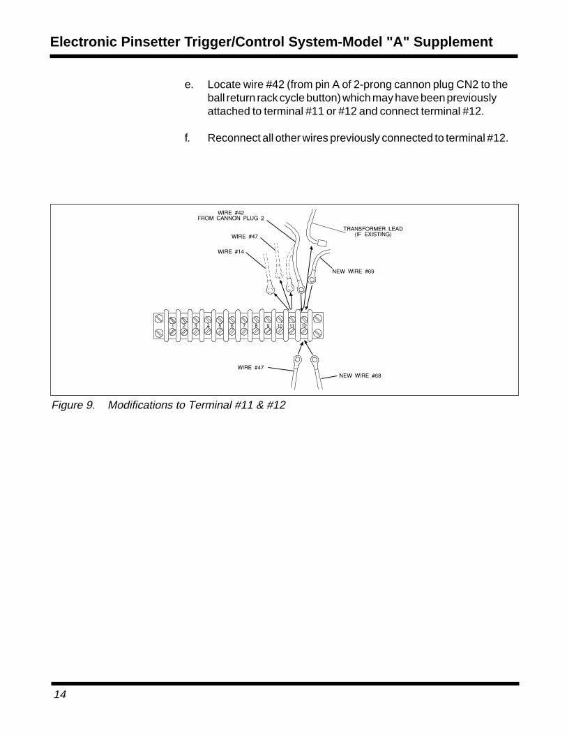
c. If wire #42 (from pin A of 2-prong cannon plug CN2 to the ballreturn rack cycle button) is connected to terminal #11, remove itand set aside.
d. Reconnect all other wires previously connected to terminal #11.
Terminal #12 - See Figure 9
Figure 8. Modifications to Terminal #9
Electronic Pinsetter Trigger/Control System-Model "A" Supplement
14
e. Locate wire #42 (from pin A of 2-prong cannon plug CN2 to theball return rack cycle button) which may have been previouslyattached to terminal #11 or #12 and connect terminal #12.
f. Reconnect all other wires previously connected to terminal #12.
Refer to Figure 10 while making connections to the new ControlBoard.
Terminal #20
Locate existing wire #22 (previously cut from the cycle relay with thespade receptacle added). Connect this wire to terminal #20 of thenew control board. (The other end of this wire should already beconnected to the cycle solenoid.)
Electronic Pinsetter Trigger/Control System-Model "A" Supplement
16
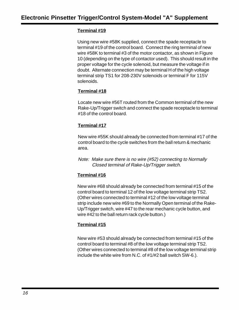
Terminal #19
Using new wire #58K supplied, connect the spade receptacle toterminal #19 of the control board. Connect the ring terminal of newwire #58K to terminal #3 of the motor contactor, as shown in Figure10 (depending on the type of contactor used). This should result in theproper voltage for the cycle solenoid, but measure the voltage if indoubt. Alternate connection may be terminal H of the high voltageterminal strip TS1 for 208-230V solenoids or terminal F for 115Vsolenoids.
Terminal #18
Locate new wire #56T routed from the Common terminal of the newRake-Up/Trigger switch and connect the spade receptacle to terminal#18 of the control board.
Terminal #17
New wire #55K should already be connected from terminal #17 of thecontrol board to the cycle switches from the ball return & mechanicarea.
Note: Make sure there is no wire (#52) connecting to NormallyClosed terminal of Rake-Up/Trigger switch.
Terminal #16
New wire #68 should already be connected from terminal #15 of thecontrol board to terminal 12 of the low voltage terminal strip TS2.(Other wires connected to terminal #12 of the low voltage terminalstrip include new wire #69 to the Normally Open terminal of the Rake-Up/Trigger switch, wire #47 to the rear mechanic cycle button, andwire #42 to the ball return rack cycle button.)
Terminal #15
New wire #53 should already be connected from terminal #15 of thecontrol board to terminal #8 of the low voltage terminal strip TS2.(Other wires connected to terminal #8 of the low voltage terminal stripinclude the white wire from N.C. of #1/#2 ball switch SW-6.).
Using new wire #54 supplied connect the spade receptacle toterminal #14 of the control board. Locate existing wire #12 or #9(from terminal #12 of the low voltage terminal strip TS2 to terminal Hof the motor start relay coil) and cut the wire approximately 3 inchesfrom the motor start relay. Strip 5/8 inch of insulation from both endsof the cut wire and connect both ends with wire #54 with the suppliedwire nut connector as shown in Figure 10. (Other wires connected toterminal 12 of the low voltage terminal strip include the black wire fromthe fuse end of the transformer).
Terminal #13
New wire #57 should already be connected from terminal #13 of thecontrol board to terminal strip TS2. (Other wires connected toterminal #6 of the low voltage terminal strip include the transformerwire).
Note: If control board does not include a 1 amp fuse, an in-linefuse holder & installation instructions are supplied to bespliced into wire #57.
Mechanical Modifications
Eliminate Mechanical Time Delay
Reposition the existing time delay stem in the rake crank housing.(Figure 11) The stem must be withdrawn at least 1/4 turn to eliminateany mechanical time delay caused by the plunger. Time delay is nowobtained electrically be the control board.
Note: Part number 11-001376-001 hex head cap screw and 12-100344-003 gasket can also be ordered and used toeliminate the mechanical time delay stem. Also the EP 80-90 heavier weight gear box oil can now be used for extraprotection. Use part no. 12-752024-000 Brunswickgearbox oil (1 Gal).
Electronic Pinsetter Trigger/Control System-Model "A" Supplement
18
Remove Mechanical Trigger Components
Cycle the pinsetter to 180°. Remove cable, tension spring, andbrackets at both ends of cable (Figure 12).
1. Remove the pin (part no. 11-360462-000) and the rakeovertravel latch selector (part no 12-100155-000) from the "C"shaft of the detector and discard these parts (Figure 13).
2. Remove the "X" washer (part no. 11-230000-000), pin (part no.12-100166-026), and 0-90 degree stop selector wire link (partno 12-100350-000) from the detector "C" shaft and discardthese parts (Figure 13).
3. Modify the clutch reset lever assembly as follows:
On older pinsetters with the cast reset lever (part no 12-100251-000 now obsolete): (See Figure 14)
- Remove the "X" washer, pin, and spring from the reset leverlatch. Save the spring for re-use.
- Install the included link (part no. 12-102033-000), "x" washerpin (part no. 12-100166-005), "X" washer (part no.11-230001-001) and existing spring (part no. 12-100149-000) as shown in Figure 14.
Figure 13. 90 Degree Overtravel Elimination
Electronic Pinsetter Trigger/Control System-Model "A" Supplement
20
On pinsetters with the flat reset lever (part no.12-100490-000): (See Figure 15)
- Install the included link (part no. 12-102033-000),lockwasher (part no. 11-195010-001) on the end of existing
bolt as shown in Figure 15.
Figure 14. Older Cast Reset Lever Modifications
Figure 15. Flat Reset Lever Modifications
4. Remove the outer cam follower assembly (part no. 12-250242-000) from the rake cam follower assembly (part no. 12-250235-000). Discard the outer cam follower and hardware shown inFigures 16 and 17.
5. Remove the rake overtravel latch (part no. 12-250033-000) andthe rake hook lever (part no. 12-250262-000) from the rake camfollower assembly and discard these parts(Figure 17).
Electronic Pinsetter Trigger/Control System-Model "A" Supplement
22
Rake Lift Rod Modifications
1. Locate the plastic blocks, 1/4" x 1-1/2" bolts, 1-1/4" dia. flatwashers and 1/4" lock nuts in the hardware package.
2. Place the plastic blocks into the slot of the rake lift upper rodends as shown in Figure 18.
Note: The bottom corners of the plastic block may need to betrimmed to fit the alternate forged rod ends.
3. Secure the plastic blocks with the 1-1/4" dia. flat washers,bolts and lock nuts tightened around the rod ends shown inFigure 18.
4. Make sure this plastic block is added to both upper rod endsto effectively fix the "V" lever connecting bolt and roller atthe top of the slot. This allows the safety shut-off system tosense when the rake is blocked and shut the moter off toprevent damage. If the roller is loose at the top of the plasticblock, check to make sure that the proper bumper assemblyis installed over the bolt and roller.
Electronic Pinsetter Trigger/Control System-Model "A" Supplement
24
Cycle Solenoid Modification
Note: For best reliability, it is recommended that the model A cyclesolenoid and starter bellcrank lever be upgraded to themodel A-2 system. Order A-2 solenoid conversion kits partno. 12-862507-000 for 208-230 Volt or part no. 12-862506-000 for 115 Volt system.
If the model A cycle solenoid is left in operation, it issuggested that the stroke be limited by drilling a hole in thesolenoid mounting bracket and installing the proper lengthbolt to limit the stroke of the solenoid plunger so it doesn'textend out all the way. (Figure 18) Position the bolt so thesolenoid plunger only extends enough to produce 1/8" gapbetween the slot in the connecting link and the pin in thestarter bellcrank lever. It is also recommended that the "X"washer pin in the bellcrank and connecting link slot be
replaced with the model A-2 pin (part no. 10-229451-000)and "0" ring (part no. 11-625538-000). This will extend thelife of the solenoid plunger, connecting link, and pin on thestarter bellcrank lever.
Figure 19. Suggested Cycle Solenoid Modifications (if not upgrading to A-2 System)
Refer to the Installation and Operations Manual for the BrunswickElectronic Pinsetter Trigger/Control System (part no. 12-902256-000). Turn to the section "Installation of the Safety Shut-offConnections" and proceed with Step #2. Since this supplementalpackage has effectively upgraded your control board and relatedwiring to the A-2 level, the rest of the A-2 installation, operations andtroubleshooting sections of the manual will directly apply.
Note: If you already have auto scoring with a take data relay, it willbe necessary to change the diode and capacitor of the relayback to its original configuration. Call the support line forfurther information.
Electronic Pinsetter Trigger/Control System-Model "A" Supplement