132
R Electronic Road Speed Limiter ERSL Applications List September 2008 Issue F rev 2 HOW TO NAVIGATE THE APPLICATIONS LIST

R
ElectronicRoad Speed
Limiter
ERSLApplications List
September 2008Issue F rev 2
HOW TO NAVIGATE THE
APPLICATIONS LIST

Click on the “Bookmarks” tabto open the navigation menu
Navigation menu opens.Click on the vehicle who’sfitting instructions youwish to view
HOW TO NAVIGATE THROUGH THEERSL APPLICATION LIST
The selected fitting instructions open at the first page.Use the page scroll facility to browse the instructions.Referal to other pages are highlighted in blue text.Click on the text to go to the refered page
Click on the “Return to fitting instructions”text to return.
0
5
25
75
95
100
0
5
25
75
95
100
0
5
25
75
95
100
0
5
25
75
95
100

STURDY Europe
1. Legal Requirements
Passenger Vehicles ............................................................................................................................... 1
More than 8 Passenger Seats ................................................................................................ 1
More than 16 Passenger Seats ............................................................................................. 1
Goods Vehicles ...................................................................................................................................... 2
2. Important Notes
ERSL Control Unit................................................................................................................................... 3
Speed Hold Utility .................................................................................................................................. 3
CANbus.................................................................................................................................................... 4
New Installation Sheet.......................................................................................................................... 5 - 6
3. Application Sheets
Aptec WilliamsAptec Williams Throttle Control .......................................................................................................... 7 - 8
Citroen
Relay ........................................................................................................................................................ 9 - 12
DAF
LF Series ................................................................................................................................................. 13 - 16
FordFocus 1.8D ............................................................................................................................................. 17 - 20
Ranger ..................................................................................................................................................... 21 - 24
Transit up to Nov 1997 ........................................................................................................................ 25 - 28
Transit from Nov 1997 ......................................................................................................................... 29 - 32
Transit from 2000 ................................................................................................................................. 33 - 36
Transit from 2005 ................................................................................................................................. 37 - 40
IsuzuNPR .......................................................................................................................................................... 41 - 44
NQR .......................................................................................................................................................... 45 - 48
Iveco
Daily EDC .13 .......................................................................................................................................... 49 - 50
LDV
Convoy 2.4D ........................................................................................................................................... 51 - 54
Mercedes-Benz
Sprinter .................................................................................................................................................... 55 - 60
CONTENTS
STURDY Europe
Mitsubishi
Canter ...................................................................................................................................................... 61- 64
PeugeotBoxer ....................................................................................................................................................... 65 - 68
Renault
Master ..................................................................................................................................................... 69 - 72
VauxhallAstra ......................................................................................................................................................... 73 - 76
Combo CDTi ............................................................................................................................................ 77 - 80
Vivaro ....................................................................................................................................................... 81 - 84
VolkswagenLT 35 and 46 .......................................................................................................................................... 85 - 90
Transporter T4 ........................................................................................................................................ 91 - 94
Transporter T5 ........................................................................................................................................ 95 - 98
4. Throttle Pedal Wiring Diagrams
Aptec Williams Throttle Control .......................................................................................................... iiiCitroen Relay .......................................................................................................................................... ivDAF LF Series ......................................................................................................................................... vFord Focus 1.8D .................................................................................................................................... viFord Ranger ............................................................................................................................................ viiFord Transit up to Nov 1997 ............................................................................................................... viiiFord Transit from Nov 1997 ................................................................................................................ ixFord Transit from 2000 ........................................................................................................................ xFord Transit from 2005 ........................................................................................................................ xiIsuzu NPR ................................................................................................................................................ xiiIsuzu NQR ............................................................................................................................................... xiiiIveco Daily EDC .13 ................................................................................................................................ xivLDV Convoy 2.4D ................................................................................................................................... xvMercedes-Benz Sprinter ....................................................................................................................... xviMitsubishi Canter .................................................................................................................................. xviiPeugeot Boxer ........................................................................................................................................ xviiiRenault Master ...................................................................................................................................... xixVauxhall Astra ......................................................................................................................................... xxVauxhall Combo CDTi ............................................................................................................................ xxiVolkswagen LT 35 and 46 .................................................................................................................... xxiiVolkswagen Transporter T4 .................................................................................................................. xxiiiVolkswagen Transporter T5 .................................................................................................................. xxivVauxhall Vivaro CDTi ............................................................................................................................ xxv

STURDY Europe
1
A GUIDE TO SPEED LIMITER REQUIREMENTS
Passenger vehicles with more than 8 passenger seats (Bus)
Diesel / LPG / Natural Gas Petrol
Vehicle Size C &U reg 36A
(Gross Design Weight) paragraph First registered Use date Stabilised speed not to exceed date Stabilised speed not to exceed
not exceeding 5000 2B & 7 1 January 2005 and after International 1 January 2005 100 kph 1 January 2005 100 kph
National only 1 January 2008 100 kph 1 January 2008 100 kph
1 October 2001 to
2C & 7 31 December 2004 International 1 January 2006 100 kph
(Euro III or later engine) National only 1 January 2007 100 kph
5001 to 7500 2A & 7 1 January 2005 and after All 1 January 2005 100 kph 1 January 2005 100 kph
1 October 2001 to
2C & 7 31 December 2004 International 1 January 2006 100 kph
(Euro III or later engine) National only 1 January 2007 100 kph
7501 to 10000
2 & 7 1 January 2005 and after All 1 January 2005 100 kph 1 January 2005 100 kph
2 & 7
2 & 7A All existing requirement set speed of 100 kph existing requirement set speed of 100 kph
10001 >
2 & 7 1 January 2005 and after All 1 January 2005 100 kph 1 January 2005 100 kph
Passenger vehicles with more than 16 passenger seats (Coach)
Diesel / LPG / Natural Gas Petrol
Vehicle Size C &U reg 36A
(Gross Design Weight) paragraph First registered Use date Stabilised speed not to exceed date Stabilised speed not to exceed
7501 to 10000
1 & 6 All existing requirement set speed at 112 kph existing requirement set speed at 112 kph
10001 >
1 & 6 All existing requirement set speed at 112 kph existing requirement set speed at 112 kph
set speed of 100 kph
1 April 1974 to 31
December 1987
1 April 1974 to 31
December 1987
All existing requirement set speed of 100 kph existing requirement
1 January 1988 to 30
September 2001
1 October 2001 to 31
December 2004
1 January 1988 to 30
September 2001
2 & 7A
Not Required
Not Required
1 October 2001 to 31
December 2004All 1 January 2005 100 kph 1 January 2005 100 kph

STURDY Europe
2
A GUIDE TO SPEED LIMITER REQUIREMENTS
Goods
Diesel / LPG / Natural Gas Petrol
Vehicle Size C &U reg 36A
(Gross Design Weight) paragraph First registered Use date Stabilised speed not to exceed date Stabilised speed not to exceed
3501 to 7500 1A & 9 1 January 2005 and after International 1 January 2005 90 kph 1 January 2005 90 kph
National only 1 January 2008 90 kph 1 January 2008 90 kph
1 October 2001 to
1B & 9 31 December 2004 International 1 January 2006 90 kph
(Euro III or later engine) National only 1 January 2007 90 kph
7501 to 1200 1A & 9 1 January 2005 and after All 1 January 2005 90 kph 1 January 2005 90 kph
1B & 8 All existing requirement 90 kph existing requirement 96 kph
1 & 8 All existing requirement 96 kph existing requirement 96 kph
7501 to 10000
2 & 9 1 January 2005 and after All existing requirement 90 kph existing requirement 90 kph
2 & 9 90 kph
2 & 9 All existing requirement 90 kph existing requirement 90 kph
Not Required
1 October 2001 to 31
December 2004All existing requirement existing requirement 90 kph
1 October 2001 to
31 December 2004
1 August 1992 to
31 December 2001
1. The category of vehicle highlighted needs particular attention. These vehicles will need to have their current settings reduced in order to comply.
1 January 1988 to 30
September 2001

STURDY Europe
3
Important Notes
ERSL Control Unit
It should be noted that, all ERSL control units supplied to the European aftermarket afterJanuarJanuarJanuarJanuarJanuary 2008y 2008y 2008y 2008y 2008, feature an optional Speed Hold facility.
Speed Hold
The speed hold utility enables the driver of a vehicle to set a limited speed for the vehicleanywhere below the maximum set speed. To activate the speed hold the driver should stabalisethe vehicle at the speed at which limitation is required, then turn on the dash mounted speedhold switch. The vehicle speed will now be limited to the selected speed until the speed holdswitch is turned off. When turned off the vehicle limited speed will return to the maximum setspeed.
To enable the speed hold facility the following steps should be taken:
1. Separate the Blue wire from the ERSL wiring loom and connect the wire to a dashboardmounted single pole On/Off switch, the other connection to the switch should be apermanent vehicle ground.
2. Using the link wire supplied, connect terminals 2 and 3 at the 18 pin ERSL wiring loomconnector.
3. Connect the ER01 programmer between the wiring loom connector and the control unitand down load the limiter program details. Change the code for table 8 to 255255255255255 andsend the updated program to the limiter.
NoteNoteNoteNoteNote: When reprogramming takes place the vehicle must be run at the maximum speedsetting of the vehicle, at full throttle, for 10 to 20 seconds on a flat road surface. Thisallows the limiter to ‘re-learn’ the new settings.The speed hold switch should be Off during this road test.
18 pin Wiring loom
connectorSingle pole
On/Off switch
Vehicle
ground
Link
wire
Dk Blue
7
6
12
1318

STURDY Europe
4
CANbus
Whilst some vehicles are equipped with an analogue speed signal that can be utilized for thespeed signal input to the ERSL, most new vehicles are now using CANbus.
Communication Area Network BUS is a high-speed data transmission network of binary vehicleinformation transmitted through limited vehicle wiring, linking all major vehicle componentstogether.
The Sturdy Limiter at this time will only operate from an Analogue Speed signal. Therefore invehicles with no Analogue Speed output we must covert the ‘CAN’ signal to an Analoguesignal for the ERSL to use.
This is achieved by the use of the Spal Canbus interface which is inserted, at a strategicpoint, into the Can network wiring of the vehicle.
The Spal CANbus unit is available from Time Instruments Ltd under Part No. 122000

STURDY Europe
5
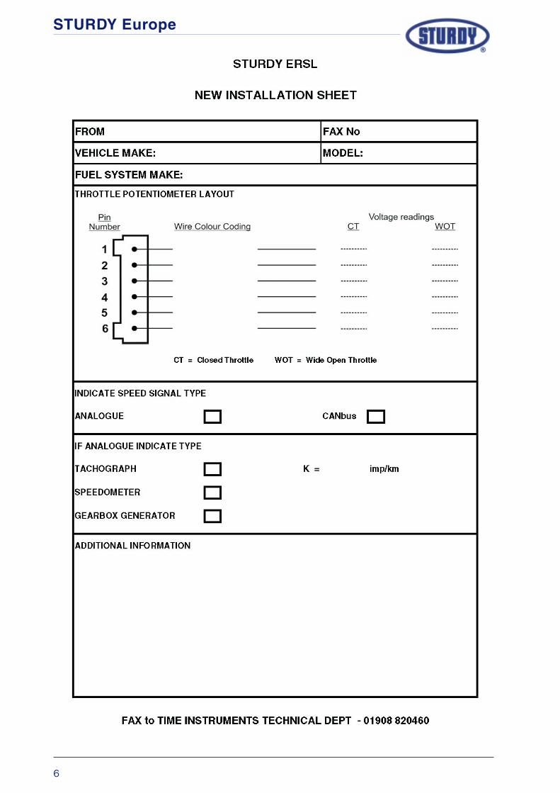
New Installations
As you are aware the light commercial vehicle sector is a constantly changing market in termsof technical development. Vehicle manufacturers regularly introduce new models or updateexisting models to keep pace with new technology.
From time to time you will be asked to install the Sturdy ERSL to a vehicle where no fittinginstructions are available or the instructions do not reflect equipment changes made by themanufacturer.
Should you require assistance from the Sturdy technical team to carry out the fitting, wouldyou please photocopy the ‘New Installation’ sheet that follows this page, enter the detailrequested and fax it to the number at the bottom of the sheet.
STURDY Europe
6

STURDY Europe
7
STURDY ELECTRONIC ROAD SPEED LIMITER
FITTING INSTRUCTIONS
FOR
Aptec Williams Throttle Control
MODELS: Various
ERSL KIT No: ER-02
KIT CONTENTS: 57D-02996 Control Unit (preset at 70 m.p.h.)
57C-03060-002 Wiring Loom
59A-03115 Fitting Accessories
Fitting Instructions
In keeping with good workshop practices the vehicle battery should be disconnected beforeattempting to install the ERSL.
Ensure that any security codes for Radios, Alarms, etc., are available before disconnectingthe battery.
Control Unit
Find a suitable position within the cab of the vehicle and secure the Control Unit, ensuringthat the site is not directly in the air flow from any heater ducts.
Wiring Loom
Remove the Purple and Brown wires from their sheath and cut the wires approximately 200mmfrom the connector, then using a butt splice supplied with the kit join the cut ends of the wirestogether. Feed the joined wires back into the protective sheath.
Connect the ERSL wiring loom to the 18pin connector in the Control Unit.
Select the ERSL loom containing three wires (Red, Black and Green) and run this to the fusepanel / rear of Tachograph / rear of electronic speedometer. Connect the RRRRRededededed wire from theERSL loom to an ignition switched positive. Connect the BlackBlackBlackBlackBlack wire from the ERSL wiringloom to a vehicle ground. Connect the GreenGreenGreenGreenGreen wire from the ERSL loom to the wire carrying aspeed signal.
Route the other half of the ERSL wiring loom to the vehicle wiring harness that runs to thethrottle potentiometer.
APTEC WILLIAM
SAPTEC W
ILLIAMS
APTEC WILLIAM
SAPTEC W
ILLIAMS
APTEC WILLIAM
S

STURDY Europe
8
Wiring Loom cont’d
At a suitable position in the potentiometer wiring harness, separate and cut the BlackBlackBlackBlackBlack wire.Using a butt splice included in the kit, connect the OrangeOrangeOrangeOrangeOrange wire from the ERSL loom to the cutwire from the throttle potentiometer.
Connect the YYYYYelloelloelloelloellowwwww wire from the ERSL loom to the cut wire that runs to the vehicle ECU.
Separate the WhitWhitWhitWhitWhiteeeee wire from the potentiometer harness and using a suitable connector,splice the PinkPinkPinkPinkPink wire from the ERSL loom to it.
Once the connections have been made wrap the looms with insulating tape to provide a neatfinish and reconnect the loom to the throttle potentiometer.
Calibration details
The Sturdy ERSL is supplied with generic calibration characteristics which may or may not besuitable for the vehicle that the throttle control is fitted to.
For advise on the suitability of the calibration contact the Sturdy Europe Technical Department.
Re-calibration / changing the set speed
The Sturdy ERSL is supplied with the operating speed set at 70 m.p.h., however the speedsetting can be easily changed to suit the customers specific requirements using the SturdyER-01 programmer.
Refer to the ER-01 Programming manual for calibrating details.
Road Test
Although the ERSL is supplied fully calibrated it is essential that, after installation, the vehiclebe road tested to allow the Control Unit to “learn” the calibration settings under road goingconditions. The vehicle should be driven with maximum throttle until the set speed is attained.The maximum throttle position should be maintained for a further 10-20 seconds whilst thecontrol unit learns the calibration settings, a reasonably flat road, clear of traffic, is requiredto carry out this operation efefefefefffffficiently iciently iciently iciently iciently and saf saf saf saf safelyelyelyelyely.....
APTE
C W
ILLI
AMS
APTE
C W
ILLI
AMS
APTE
C W
ILLI
AMS
APTE
C W
ILLI
AMS
APTE
C W
ILLI
AMS

STURDY Europe
9
STURDY ELECTRONIC ROAD SPEED LIMITER
FITTING INSTRUCTIONS
FOR
CITROEN RELAY
MODELS: Diesel models from March 2007
ERSL KIT No: ER-07
KIT CONTENTS: 57D-03668 Control Unit (preset at 70 m.p.h.)
57C-03060-005 Wiring Loom
59A-03386 Fitting Accessories
FITTING INSTRUCTIONS
In keeping with good workshop practices the vehicle battery should be disconnected beforeattempting to install the ERSL.
Ensure that any security codes for Radios, Alarms, etc., are available before disconnectingthe battery.
Control Unit
The control unit can be fitted in the area below the drivers side of the dash panel, usingsuitable screws or adhesive.
Wiring Loom
Connect the ERSL wiring loom to the 18pin connector in the Control Unit.
Run the ERSL wiring loom containing 10 wires to the throttle pedal assembly.
Disconnect the wiring plug at the throttle position potentiometer, remove the protective plasticsleeve and approximately 200mm of canvas wrap from the wiring loom to the potentiometerplug.
Refering to the diagram on page iii, separate the Brown/blackBrown/blackBrown/blackBrown/blackBrown/black wire from the potentiometerloom and cut the wire at a convenient position. Using the butt splices supplied in the ERSL kit,connect the Green/yellowGreen/yellowGreen/yellowGreen/yellowGreen/yellow wire from the ERSL loom to the throttle pedal side of the cutwire, then connect the TTTTTan/redan/redan/redan/redan/red wire from the ERSL loom to the EMC side of the cut wire.
Separate the Blue/blackBlue/blackBlue/blackBlue/blackBlue/black wire from the potentiometer loom and again cut the wire at aconvenient position. Using the butt splices supplied connect the OrangeOrangeOrangeOrangeOrange wire from the ERSLloom to the throttle pedal side of the cut wire, then connect the YYYYYelloelloelloelloellowwwww wire from the ERSLloom to the EMC side of the cut wire.
CITR
OEN
CITR
OEN
CITR
OEN
CITR
OEN
CITR
OEN

STURDY Europe
10
Wiring Loom cont’d
Connect the PinkPinkPinkPinkPink wire from the ERSL loom, in series, to the Brown/whiteBrown/whiteBrown/whiteBrown/whiteBrown/white wire in thepotentiometer loom. Connect the Black/yellowBlack/yellowBlack/yellowBlack/yellowBlack/yellow wire from the ERSL loom, in series, with thePurple/blackPurple/blackPurple/blackPurple/blackPurple/black wire in the potentiometer loom.
Once the connections have been made wrap the looms with insulating tape to provide a neatfinish and reconnect the loom to the throttle potentiometer.
If engine rev limitation is required, the BlueBlueBlueBlueBlue wire from the ERSL wiring loom should be routedto the alternator and connected to the W terminal.
To complete the wiring for the ERSL there are a further three connections to be made, thesebeing the Red, Black and Green wires from the ERSL wiring loom. Where these connectionsshould be made will depend on the vehicle having either a tachograph or an electronicspeedometer fitted.
Tachograph fitted
Select the ERSL loom containing three wires (Red, Black and Green) and run this to the rearof the tachograph. At this point, using the butt splices supplied, connect the BlackBlackBlackBlackBlack wire inthe ERSL loom to the tachograph negative (pin A5). The RedRedRedRedRed wire in the ERSL loom is connectedto the ignition switched positive (pin A3) and the GreenGreenGreenGreenGreen wire to the road speed signal ateither pin B7 or pin D3.
If these actions result in the breaking of a tachograph seal, the seal must be replaced by aDepartment of Transport approved tachograph calibration centre.
Electronic Speedometer fitted
At the rear of the speedometer can be found a Black plug containing an Green/greyGreen/greyGreen/greyGreen/greyGreen/grey wire,the GreenGreenGreenGreenGreen wire from the ERSL loom should be spliced to this wire to obtain a road speedsignal. The Red and Black wires from the ERSL loom should be routed to the Brake PedalSwitch where the BlackBlackBlackBlackBlack wire should be spliced to the Negative wire from the switch and theRedRedRedRedRed wire spliced to the Ignition Positive wire to the switch.
CIT
RO
ENC
ITR
OEN
CIT
RO
ENC
ITR
OEN
CIT
RO
EN

STURDY Europe
11
Calibration details
The Sturdy ERSL is supplied with a generic set of calibration characteristics. For the limiter tooperate correctly the characteristics listed below should be programmed into the ERSL ControlUnit.
TABLE PROGRAM CODE LEVEL
1 Speed setting Legal/customer requirement
2 Pole setting (x 1000imp) 13 7.5
3 Error gain 8 9
4 Response gain 176 12
5 % of WOT 8 52%
6 Not used
7 Not used
8 Engine rev setting
9 Eng.Sp Alternator poles 2.5
10 Eng.Sp Error gain 6
11 Eng.Sp Response gain 7
12 Eng.Sp % of WOT 50%
13 (L) Min. voltage 136 9%
13 (H) Max voltage (8+18) 93%
14 Not used
15 Not used
Re-calibration / changing the set speed
The Sturdy ERSL is supplied with the operating speed set at 70 m.p.h., however the speedsetting can be easily changed to suit the legal or customers specific requirements using theSturdy ER-01 programmer.
Refer to the ER-01 Programming manual for programming details.
Road Test
Although the ERSL is supplied fully calibrated it is essential that, after installation, the vehiclebe road tested to allow the Control Unit to “learn” the calibration settings under road goingconditions. The vehicle should be driven with maximum throttle until the set speed is attained.The maximum throttle position should be maintained for a further 10-20 seconds whilst thecontrol unit learns the calibration settings, a reasonably flat road, clear of traffic, is requiredto carry out this operation efefefefefffffficiently iciently iciently iciently iciently and saf saf saf saf safelyelyelyelyely.....
CITR
OEN
CITR
OEN
CITR
OEN
CITR
OEN
CITR
OEN

STURDY Europe
12
CIT
RO
ENC
ITR
OEN
CIT
RO
ENC
ITR
OEN
CIT
RO
EN

STURDY Europe
13
STURDY ELECTRONIC ROAD SPEED LIMITER
FITTING INSTRUCTIONS
FOR
DAF LF Series
MODELS: All 45 models up to 7.5 tonnes
ERSL KIT No: ER-02
KIT CONTENTS: 57D-02996 Control Unit (preset at 70 m.p.h.)
57C-03060-002 Wiring Loom
59A-03115 Fitting Accessories
FITTING INSTRUCTIONS
In keeping with good workshop practices the vehicle battery should be disconnected beforeattempting to install the ERSL.
Ensure that any security codes for Radios, Alarms, etc., are available before disconnectingthe battery.
Control Unit
Find a suitable position within the cab of the vehicle and secure the Control Unit, ensuringthat the site is not directly in the air flow from any heater ducts.
Wiring Loom
Remove the steering column shroud to gain access to the throttle pedal potentiometer andto enable the tachograph to be removed.
In the ERSL wiring loom, remove the Purple and Brown wires from their sheath and cut thewires approximately 200mm from the connector, then using a butt splice supplied with the kitjoin the cut ends of the wires together. Feed the joined wires back into the protective sheath.
Connect the ERSL wiring loom to the 18pin connector in the Control Unit.
Select the ERSL loom containing three wires (Red, Black and Green) and run this to the rearof the tachograph. At this point, using the butt splices supplied, connect the BlackBlackBlackBlackBlack wire inthe ERSL loom to the tachograph negative (pin A5). The RedRedRedRedRed wire in the ERSL loom is connectedto the ignition switched positive (pin A3) and the GreenGreenGreenGreenGreen wire to the road speed signal ateither pin B7 or pin D3.
If these actions result in the breaking of a tachograph seal, the seal must be replaced by aDepartment of Transport approved tachograph calibration centre.
DAF
DAF
DAF
DAF
DAF

STURDY Europe
14
Wiring Loom cont’d
Route the other half of the ERSL wiring loom to the vehicle wiring harness that runs to thethrottle potentiometer.
At a suitable position in the potentiometer wiring harness, separate and cut the GreyGreyGreyGreyGrey wirenumber 46794679467946794679. Using a butt splice included in the kit, connect the OrangeOrangeOrangeOrangeOrange wire from theERSL loom to the cut GreGreGreGreGreyyyyy wire from the throttle potentiometer.
Connect the YYYYYelloelloelloelloellowwwww wire from the ERSL loom to the cut GreGreGreGreGreyyyyy wire that runs to the vehicleECU.
Separate the Grey Grey Grey Grey Grey wire number 46804680468046804680 from the potentiometer harness and using a suitableconnector, splice the PinkPinkPinkPinkPink wire from the ERSL loom to it (see wiring diagram on page v).
Once the connections have been made wrap the looms with insulating tape to provide a neatfinish and reconnect the loom to the throttle potentiometer.
Calibration details
The Sturdy ERSL is supplied with a generic set of calibration characteristics. For the limiter tooperate correctly the characteristics listed below should be programmed into the ERSL ControlUnit.
TABLE PROGRAM CODE LEVEL
1 Speed setting Legal/customer requirement
2 Pole setting (x 1000imp) 32 17
3 Error gain 5 6
4 Response gain 144 10
5 % of WOT 4 38%
6 Not used
7 Not used
8 Engine rev setting Disabled
9 Eng.Sp Alternator poles 2.5
10 Eng.Sp Error gain 6
11 Eng.Sp Response gain 7
12 Eng.Sp % of WOT 50%
13 (L) Min. voltage 136 9%
13 (H) Max voltage (8+128) 93%
14 Not used
15 Not used
DAF
DAF
DAF
DAF
DAF

STURDY Europe
15
Re-calibration / changing the set speed
The Sturdy ERSL is supplied with the operating speed set at 70 m.p.h., however the speedsetting can be easily changed to suit the legal or customers specific requirements using theSturdy ER-01 programmer.
Refer to the ER-01 Programming manual for programming details.
Road Test
Although the ERSL is supplied fully calibrated it is essential that, after installation, the vehiclebe road tested to allow the Control Unit to “learn” the calibration settings under road goingconditions. The vehicle should be driven with maximum throttle until the set speed is attained.The maximum throttle position should be maintained for a further 10-20 seconds whilst thecontrol unit learns the calibration settings, a reasonably flat road, clear of traffic, is requiredto carry out this operation efefefefefffffficiently iciently iciently iciently iciently and saf saf saf saf safelyelyelyelyely.....
DAF
DAF
DAF
DAF
DAF

STURDY Europe
16
DAF
DAF
DAF
DAF
DAF

STURDY Europe
17
STURDY ELECTRONIC ROAD SPEED LIMITER
FITTING INSTRUCTIONS
FOR
FORD FOCUS 1.8D
MODELS: 1.8 DIESEL (2002)
ERSL KIT No: ER-06
KIT CONTENTS: 57D-03668 Control Unit (pre-set at 70 mph)
57C-0306-005 Wiring Loom
59A-03362 Fitting Accessories
Fitting Instructions
In keeping with good workshop practices the vehicle battery should be disconnected beforeattempting to install the ERSL.
Ensure that any security codes for Radios, Alarms, etc., are available before disconnectingthe battery.
Control Unit
The control unit can be fitted inside the driver compartment, against the engine bulkhead,directly behind the throttle pedal position sensor. A mounting bracket will have to bemanufactured to allow the control unit to be fixed to an existing anchor point.
Wiring Loom
Connect the ERSL wiring loom to the 18pin connector in the Control Unit.
Run the ERSL wiring loom along the side of the vehicle ECM up to the vehicle wiring loomcarrying the throttle potentiometer control wires.
Referring to the schematic diagram on page vi, separate the WhiteWhiteWhiteWhiteWhite wire (pin 5) from thepotentiometer loom and cut the wire at a convenient position.
Using the butt splices supplied in the ERSL kit, connect the PurplePurplePurplePurplePurple wire from the ERSL loomto the throttle pedal side of the cut wire. Then connect the BrownBrownBrownBrownBrown wire from the ERSL loomto the ECM side of the cut wire.
Separate the White/redWhite/redWhite/redWhite/redWhite/red wire (pin 4) from the potentiometer loom, again cutting the wire ata convenient position.
FOR
DFO
RD
FOR
DFO
RD
FOR
D

18
Wiring Loom cont’d
Connect the Green/yellowGreen/yellowGreen/yellowGreen/yellowGreen/yellow wire from the ERSL loom to the pedal side of the cut wire andthe TTTTTan/redan/redan/redan/redan/red wire from the ERSL loom to the ECM side of the cut wire.
Separate the White/blueWhite/blueWhite/blueWhite/blueWhite/blue wire (pin 7) from the potentiometer loom and cut the wire. Connectthe OrangeOrangeOrangeOrangeOrange wire from the ERSL loom to the pedal side of the cut wire and the YYYYYelloelloelloelloellowwwww wirefrom the ERSL loom to the ECM side of the cut wire.
Connect the PinkPinkPinkPinkPink wire from the ERSL loom in series with the Brown/blueBrown/blueBrown/blueBrown/blueBrown/blue wire (pin 2) in thepotentiometer loom.
Connect the Black/yellowBlack/yellowBlack/yellowBlack/yellowBlack/yellow wire from the ERSL loom in series with the Brown/redBrown/redBrown/redBrown/redBrown/red wire (pin6) in the potentiometer loom.
Once the connections have been made, wrap the modified loom with insulating tape to providea neat finish, then reconnect the loom to the throttle potentiometer.
If the engine rev signal wire is required, this should be routed through a grommet in theengine bulkhead and then on to the alternator where it should be connected to the ‘W’terminal via the in-line fuse supplied.
To complete the wiring for the ERSL there are a further three connections to be made, GreenGreenGreenGreenGreenwire to road speed signal, RedRedRedRedRed wire to ignition positive and BlackBlackBlackBlackBlack wire to negative.
A speed signal for the ERSL can be obtained by splicing the GreenGreenGreenGreenGreen wire from the ERSL loomto the Brown/yellowBrown/yellowBrown/yellowBrown/yellowBrown/yellow wire in the vehicle speed sensor fly lead.
The fly lead can be located on top of the transverse gearbox housing, level with the left-handside of the battery. Disconnect the fly-lead and feed the lead back to the rear of thetransmission housing - access to the lead is easiest from underneath the vehicle.
To the right of the throttle pedal assy is an access hole through to the engine compartment,use this point to route the GreenGreenGreenGreenGreen and BlueBlueBlueBlueBlue wires from the ERSL loom as required.
FOR
DFO
RD
FOR
DFO
RD
FOR
D

19
Calibration details
The Sturdy ERSL is supplied with a generic set of calibration characteristics. For the limiter tooperate correctly the characteristics listed below should be programmed into the ERSL ControlUnit.
TABLE PROGRAM CODE LEVEL
1 Speed setting Legal/Customer Requirement
2 Pole setting (x 1000imp) 13 7.5
3 Error gain 5 6
4 Response gain 144 10
5 % of WOT 4 38%
6 Not used
7 Not used
8 Engine rev setting
9 Eng.Sp Alternator poles 12.5
10 Eng.Sp Error gain 6
11 Eng.Sp Response gain 7
12 Eng.Sp % of WOT 50%
13 (L) Min voltage 136 9%
13 (H) Max voltage (8+128) 93%
14 Not used
15 Not used
Re-calibration / changing the set speed
The Sturdy ERSL is supplied with the operating speed set at 70 m.p.h., however the speedsetting can be easily changed to suit the customers specific requirements using the SturdyER-01 programmer.
Refer to the ER-01 Programming manual for calibrating details.
Road Test
Although the ERSL is supplied fully calibrated it is essential that, after installation, the vehiclebe road tested to allow the Control Unit to “learn” the calibration settings under road goingconditions.
The vehicle should be driven with maximum throttle until the set speed is attained. The maximumthrottle position should be maintained for a further 10-20 seconds whilst the control unitlearns the calibration settings, a reasonably flat road, clear of traffic, is required to carry outthis operation efefefefefffffficiently iciently iciently iciently iciently and saf saf saf saf safelyelyelyelyely.....
FOR
DFO
RD
FOR
DFO
RD
FOR
D

STURDY Europe
20
FOR
DFO
RD
FOR
DFO
RD
FOR
D

STURDY Europe
21
STURDY ELECTRONIC ROAD SPEED LIMITER
FITTING INSTRUCTIONS
FOR
FORD RANGER
MODELS: All
ERSL KIT No: ER-06
KIT CONTENTS: 57D-03668 Control Unit
57C-03060-005 Wiring Loom
59A-03362 Fitting Accessories
Fitting Instructions
In keeping with good workshop practices the vehicle battery should be disconnected beforeattempting to install the ERSL.
Ensure that any security codes for Radios, Alarms, etc., are available before disconnectingthe battery.
Control Unit
The control unit can be fitted in the area below the drivers side dash panel or a suitable placeof your choosing, using suitable screws or adhesive.
Wiring Loom
Remove the Purple and Brown wires from their sheath and cut the wires approximately 200mmfrom the connector, then using a butt splice supplied with the kit join the cut ends of the wirestogether. Feed the joined wires back into the protective sheath.
Connect the ERSL wiring loom to the 18pin connector in the Control Unit.
Run the ERSL loom containing 10 wires down to the throttle pedal assembly.
Disconnect the wiring plug at the throttle position potentiometer, remove the protective plasticsleeve and approximately 200mm of canvas wrap from the wiring loom to the potentiometerplug.
Referring to the schematic diagram on page vii, separate the PinkPinkPinkPinkPink wire (pin 6) from thepotentiometer loom and cut the wire at a convenient position.
FOR
DFO
RD
FOR
DFO
RD
FOR
D

STURDY Europe
22
Wiring Loom cont’d
Using the butt splices supplied in the ERSL kit, connect the Green/yellowGreen/yellowGreen/yellowGreen/yellowGreen/yellow wire from theERSL loom to the throttle pedal side of the cut wire. Then connect the TTTTTan/redan/redan/redan/redan/red wire from theERSL loom to the ECM side of the cut wire.
Separate the RedRedRedRedRed wire (pin 3) from the potentiometer loom, again cutting the wire at aconvenient position.
Connect the OrangeOrangeOrangeOrangeOrange wire from the ERSL loom to the pedal side of the cut wire and theYYYYYelloelloelloelloellowwwww wire from the ERSL loom to the ECM side of the cut wire.
Connect the PinkPinkPinkPinkPink wire and the Black/yellowBlack/yellowBlack/yellowBlack/yellowBlack/yellow wire from the ERSL loom in series with theBrown/blackBrown/blackBrown/blackBrown/blackBrown/black wire (pin 1) in the potentiometer loom.
Once the connections have been made wrap the loom with insulating tape to provide a neatfinish and re-connect the loom to the throttle potentiometer.
If the engine rev limitation is required, the Blue wire from the ERSL loom should be routedand connected to the ‘W’ terminal on the alternator.
To complete the wiring for the ERSL there are a further three connections to be made, Greenwire to road speed signal, Red wire to ignition positive and Black wire to a vehicle negative.Where these connections are made will depend on the vehicle having either a tachograph oran electronic speedometer fitted.
Tachograph fitted
The ERSL loom containing the Green, Red and Black wires should be routed to the back ofthe tachograph. Using an appropriate butt-splice, connect the RedRedRedRedRed wire to the tachographignition positive (pin A3), connect the BlackBlackBlackBlackBlack wire to the tachograph negative (pin A5). TheGreenGreenGreenGreenGreen wire should be connected to either terminal B7 or D3 in the rear of the tachographcasing.
These actions may result in the breaking of a tachograph seal, if the vehicle falls within thecategory of vehicles governed by EC tachograph regulations, this seal must be replaced by aDpt of transport approved tachograph calibration centre.
Electronic Speedometer fitted
In cases where an electronic speedometer is fitted to the vehicle, a speed signal for the ERSLcan be obtained at the rear of the speedometer.
At the rear of the speedometer is a Green plug containing an OrangeOrangeOrangeOrangeOrange wire ( pin 1). TheGreenGreenGreenGreenGreen wire from the ERSL loom should be spliced to this wire using an appropriate butt-splice.
The Black and Red wires from the ERSL loom should be routed to the Brake Light Switch,where the RedRedRedRedRed wire is connected to an ignition switched positive and the BlackBlackBlackBlackBlack wire connectedto a vehicle earth.
FOR
DFO
RD
FOR
DFO
RD
FOR
D

STURDY Europe
23
Calibration details
The Sturdy ERSL is supplied with a generic set of calibration characteristics. For the limiter tooperate correctly the characteristics listed below should be programmed into the ERSL ControlUnit.
TABLE PROGRAM CODE LEVEL
1 Speed setting Legal/Customer Spec
2 Pole setting (x 1000imp) 12 7
3 Error gain 7 8
4 Response gain 160 11
5 % of WOT 8 52%
6 Not used
7 Not used
8 Engine rev setting
9 Eng.Sp Alternator poles
10 Eng.Sp Error gain 6
11 Eng.Sp Response gain 7
12 Eng.Sp % of WOT 50%
13 (L) Min voltage 136 9%
13 (H) Max voltage (8+128) 93%
14 Not used
15 Not used
Re-calibration / changing the set speed
The Sturdy ERSL is supplied with the operating speed set at 70 mph and the engine revlimitation disabled, however the speed setting can be easily changed to suit the customersspecific requirements and the engine rev limiter enabled using the Sturdy ER-01 programmer.
Refer to the ER-01 Programming manual for calibrating details.
Road Test
After installation or re-calibration it is essential that the vehicle is road tested to allow theControl Unit to “learn” the calibration settings under road going conditions.
The vehicle should be driven with maximum throttle until the set speed is attained. The maximumthrottle position should be maintained for a further 10-20 seconds whilst the control unitlearns the calibration settings, a reasonably flat road, clear of traffic, is required to carry outthis operation efefefefefffffficientlyicientlyicientlyicientlyiciently and safsafsafsafsafelyelyelyelyely.
FOR
DFO
RD
FOR
DFO
RD
FOR
D

STURDY Europe
24
FOR
DFO
RD
FOR
DFO
RD
FOR
D

STURDY Europe
25
STURDY ELECTRONIC ROAD SPEED LIMITER
FITTING INSTRUCTIONS
FOR
FORD TRANSIT
MODELS: Turbo Diesel up to NOV’97
ERSL KIT No: ER-02
KIT CONTENTS: 57D-02996 Control Unit (pre-set at 70 mph)
57C-03060-002 Wiring Loom
59A-03115 Fitting Accessories
Fitting Instructions
In keeping with good workshop practices the vehicle battery should be disconnected beforeattempting to install the ERSL.
Ensure that any security codes for Radios, Alarms, etc., are available before disconnectingthe battery.
Control Unit
The control unit should be sited in a convenient position within the cab or engine compartmentof the vehicle.
Wiring Loom
Connect the ERSL wiring loom to the 18pin connector in the Control Unit.
Run the ERSL loom containing the purple, brown, orange, yellow and blue wires down to thethrottle pedal assembly.
Disconnect the vehicle wiring from the throttle position potentiometer, feed the wiring togetherwith plugs and grommet and the ERSL loom through the engine bay bulkhead where it will bemore convenient to work on.
Refer to the schematic diagram on page viii.
Separate the GreyGreyGreyGreyGrey wire (pin 3) from the potentiometer loom and cut the wire at a convenientposition.
Using the butt splices supplied in the ERSL kit, connect the PurplePurplePurplePurplePurple wire from the ERSL loomto the throttle pedal side of the cut wire. Then connect the BrownBrownBrownBrownBrown wire from the ERSL loomto the ECM side of the cut wire.
FOR
DFO
RD
FOR
DFO
RD
FOR
D

STURDY Europe
26
Wiring Loom cont’d
Separate the WhiteWhiteWhiteWhiteWhite wire from the potentiometer loom, again cutting the wire at a convenientposition.
Connect the OrangeOrangeOrangeOrangeOrange wire from the ERSL loom to the pedal side of the cut wire and theYYYYYelloelloelloelloellowwwww wire from the ERSL loom to the ECM side of the cut wire.
Connect the Pink Pink Pink Pink Pink wire from the ERSL loom in series with the BrownBrownBrownBrownBrown wire (pin 4) in thepotentiometer loom.
Once the connections have been made wrap the looms with tape to provide a neat finish,feed the wiring loom back into the cab of the vehicle (re-seating the grommet) and re-connectthe loom to the throttle potentiometer.
If the engine rev signal wire is required, this should be routed back through the potentiometerloom grommet and then on to the alternator where it should be connected to the ‘W’ terminalvia the in-line fuse supplied.
To complete the wiring for the ERSL there are a further three connections to be made, GreenGreenGreenGreenGreenwire to road speed signal, RedRedRedRedRed wire to ignition positive and BlackBlackBlackBlackBlack wire to negative. Wherethese connections should be made will depend on the vehicle having either a tachograph ora mechanical speedometer fitted.
Tachograph fitted
The ERSL loom containing the Green, Red and Black wires should be routed to the back ofthe tachograph. Using an appropriate butt-splice connect the RedRedRedRedRed wire to the tachographignition positive (pin A3), connect the BlackBlackBlackBlackBlack wire to the tachograph negative (pin A5). TheGreenGreenGreenGreenGreen wire should be connected to either terminal B7 or D3 in the rear of the tachographcasing.
These actions will normally result in the breaking of a tachograph seal, if the vehicle fallswithin the category of vehicles governed by EC tachograph regulations, this seal must bereplaced by a Dpt of transport approved tachograph calibration centre.
Mechanical Speedometer fitted
In cases where a cable driven speedometer is fitted to the vehicle an in-line speed sensor(part no TIM4001-65H) and adapter (part no SXC-01374) must be installed to provide aspeed signal for the ERSL.
The ERSL loom containing the Green, Red and Black wires should be routed together with theelectrical lead from the speed sensor to the fuse board area below the dashboard. At thispoint the RedRedRedRedRed wire from the ERSL loom and the BrownBrownBrownBrownBrown wire from the speed sensor should betwinned together and connected to an ignition positive at the fuse board. The BlackBlackBlackBlackBlack wirefrom the ERSL and the BlueBlueBlueBlueBlue wire from the speed sensor should be twinned together andconnected to a vehicle negative. The GreenGreenGreenGreenGreen wire from the ERSL loom should be spliced tothe Green/YGreen/YGreen/YGreen/YGreen/Yelloelloelloelloellowwwww wire from the speed sensor.
FOR
DFO
RD
FOR
DFO
RD
FOR
D

STURDY Europe
27
Calibration details
The Sturdy ERSL is supplied with a generic set of calibration characteristics. For the limiter tooperate correctly the characteristics listed below should be programmed into the ERSL ControlUnit.
TABLE PROGRAM CODE LEVEL
1 Speed setting Legal/customer requirement
2 Pole setting (x 1000imp) 14 8
3 Error gain 5 6
4 Response gain 144 10
5 % of WOT 11 62%
6 Not used
7 Not used
8 Engine rev setting
9 Eng.Sp Alternator poles 17
10 Eng.Sp Error gain 6
11 Eng.Sp Response gain 7
12 Eng.Sp % of WOT 50%
13 (L) Min voltage 255 16%
13 (H) Max voltage (15+240) 100%
14 Not used
15 Not used
Cable Clamp Gearbox Adaptor
Speedometer Drive Cable Speed Signal Generator
FOR
DFO
RD
FOR
DFO
RD
FOR
D
STURDY Europe
28
Re-calibration / changing the set speed
The Sturdy ERSL is supplied with the operating speed set at 70 mph, however the speedsetting can be easily changed to suit the customers specific requirements using the SturdyER-01 programmer.
Refer to the ER-01 Programming manual for calibrating details.
Road Test
After installation or re-calibration it is essential that the vehicle is road tested to allow theControl Unit to “learn” the calibration settings under road going conditions.
The vehicle should be driven with maximum throttle until the set speed is attained. The maximumthrottle position should be maintained for a further 10-20 seconds whilst the control unitlearns the calibration settings, a reasonably flat road, clear of traffic, is required to carry outthis operation efefefefefffffficientlyicientlyicientlyicientlyiciently and safsafsafsafsafelyelyelyelyely.
FOR
DFO
RD
FOR
DFO
RD
FOR
D

STURDY Europe
29
STURDY ELECTRONIC ROAD SPEED LIMITER
FITTING INSTRUCTIONS
FOR
FORD TRANSIT
MODELS: Turbo Diesel from NOV’97
ERSL KIT No: ER-02
KIT CONTENTS: 57D-02996 Control Unit (pre-set at 70 mph)
57C-03060-002 Wiring Loom
59A-03115 Fitting Accessories
Fitting Instructions
In keeping with good workshop practices the vehicle battery should be disconnected beforeattempting to install the ERSL.
Ensure that any security codes for Radios, Alarms, etc., are available before disconnectingthe battery.
Control Unit
The control unit can be fitted to the top of the glove box compartment using suitable screwsor adhesive. Access is achieved by removing the storage tray in the top of the dashboard infront of the passenger seats.
Wiring Loom
Connect the ERSL wiring loom to the 18pin connector in the Control Unit.
Run the ERSL loom containing the purple, brown, orange, yellow and blue wires down to thethrottle pedal assembly.
Disconnect the wiring plug and socket at the throttle position potentiometer, removeapproximately 200mm of canvas wrap from the wiring on the ECM side of the connector.
Referring to the schematic diagram on page ix, separate the GreyGreyGreyGreyGrey wire (pin 5) from thepotentiometer loom and cut the wire at a convenient position.
Using the butt splices supplied in the ERSL kit, connect the PurplePurplePurplePurplePurple wire from the ERSL loomto the throttle pedal side of the cut wire. Then connect the BrownBrownBrownBrownBrown wire from the ERSL loomto the ECM side of the cut wire.
FOR
DFO
RD
FOR
DFO
RD
FOR
D

STURDY Europe
30
Wiring Loom cont’d
Separate the WhiteWhiteWhiteWhiteWhite wire (pin 1) from the potentiometer loom, again cutting the wire at aconvenient position.
Connect the OrangeOrangeOrangeOrangeOrange wire from the ERSL loom to the pedal side of the cut wire and theYYYYYelloelloelloelloellowwwww wire from the ERSL loom to the ECM side of the cut wire.
Connect the PinkPinkPinkPinkPink wire from the ERSL loom in series with the BrownBrownBrownBrownBrown wire (pin 7) in thepotentiometer loom.
Once the connections have been made wrap the looms with insulating tape to provide a neatfinish and re-connect the loom to the throttle potentiometer.
If the engine rev signal wire is required, this should be routed through a grommet in theengine bulkhead and then on to the alternator where it should be connected to the ‘W’terminal via the in-line fuse supplied.
To complete the wiring for the ERSL there are a further three connections to be made, GreenGreenGreenGreenGreenwire to road speed signal, RedRedRedRedRed wire to ignition positive and BlackBlackBlackBlackBlack wire to negative. Wherethese connections should be made will depend on the vehicle having either a tachograph oran electronic speedometer fitted.
Tachograph fitted
The ERSL loom containing the Green, Red and Black wires should be routed to the back ofthe tachograph. Using an appropriate butt-splice connect the RedRedRedRedRed wire to the tachographignition positive (pin A3), connect the BlackBlackBlackBlackBlack wire to the tachograph negative (pin A5). TheGreenGreenGreenGreenGreen wire should be connected to either terminal B7 or D3 in the rear of the tachographcasing.
These actions will normally result in the breaking of a tachograph seal, if the vehicle fallswithin the category of vehicles governed by EC tachograph regulations, this seal must bereplaced by a Dpt of transport approved tachograph calibration centre.
Electronic Speedometer fitted
In cases where an electronic speedometer is fitted to the vehicle, a speed signal for the ERSLcan be obtained at the rear of the speedometer.
At the rear of the speedometer is a Black connector plug. Pin 5 (White/blueWhite/blueWhite/blueWhite/blueWhite/blue) of this plugcarries the speed signal from the gearbox transducer, the GreenGreenGreenGreenGreen wire from the ERSL loomshould be spliced to this wire using an appropriate butt-splice.
FOR
DFO
RD
FOR
DFO
RD
FOR
D

STURDY Europe
31
Calibration details
The Sturdy ERSL is supplied with a generic set of calibration characteristics. For the limiter tooperate correctly the characteristics listed below should be programmed into the ERSL ControlUnit.
TABLE PROGRAM CODE LEVEL
1 Speed setting Legal/customer requirement
2 Pole setting (x 1000imp) 13 7.5
3 Error gain 5 6
4 Response gain 14 10
5 % of WOT 11 62%
6 Not used
7 Not used
8 Engine rev setting
9 Eng.Sp Alternator poles 12.5
10 Eng.Sp Error gain 6
11 Eng.Sp Response gain 7
12 Eng.Sp % of WOT 50%
13 (L) Min voltage 255 16%
13 (H) Max voltage (15+240) 100%
14 Not used
15 Not used
Re-calibration / changing the set speed
The Sturdy ERSL is supplied with the operating speed set at 70 mph, however the speedsetting can be easily changed to suit the customers specific requirements using the SturdyER-01 programmer.
Refer to the ER-01 Programming manual for calibrating details.
Road Test
After installation or re-calibration it is essential that the vehicle is road tested to allow theControl Unit to “learn” the calibration settings under road going conditions.
The vehicle should be driven with maximum throttle until the set speed is attained. The maximumthrottle position should be maintained for a further 10-20 seconds whilst the control unitlearns the calibration settings, a reasonably flat road, clear of traffic, is required to carry outthis operation efefefefefffffficientlyicientlyicientlyicientlyiciently and safsafsafsafsafelyelyelyelyely.
FOR
DFO
RD
FOR
DFO
RD
FOR
D

STURDY Europe
32
FOR
DFO
RD
FOR
DFO
RD
FOR
D

STURDY Europe
33
STURDY ELECTRONIC ROAD SPEED LIMITER
FITTING INSTRUCTIONS
FOR
FORD TRANSIT 2000
MODELS: Dura torque (2000)
ERSL KIT No: ER-06
KIT CONTENTS: 57D-03668 Control Unit (pre-set at 70 mph)
57C-03060-005 Wiring Loom
59A-03362 Fitting Accessories
Fitting Instructions
In keeping with good workshop practices the vehicle battery should be disconnected beforeattempting to install the ERSL.
Ensure that any security codes for Radios, Alarms, etc., are available before disconnectingthe battery.
Control Unit
The control unit can be fitted in the area above the glove box compartment using suitablescrews or adhesive. Access is achieved by removing the storage tray in the top of the dashboardin front of the passenger seats.
Wiring Loom
Connect the ERSL wiring loom to the 18pin connector in the Control Unit.
Run the ERSL loom containing 10 wires down to the throttle pedal assembly.
Disconnect the wiring plug at the throttle position potentiometer, remove the protective plasticsleeve and approximately 200mm of canvas wrap from the wiring loom to the potentiometerplug.
Referring to the schematic diagram on page x, separate the Grey/orangeGrey/orangeGrey/orangeGrey/orangeGrey/orange wire (pin 5) fromthe potentiometer loom and cut the wire at a convenient position.
Using the butt splices supplied in the ERSL kit, connect the PurplePurplePurplePurplePurple wire from the ERSL loomto the throttle pedal side of the cut wire. Then connect the BrownBrownBrownBrownBrown wire from the ERSL loomto the ECM side of the cut wire.
FOR
DFO
RD
FOR
DFO
RD
FOR
D

STURDY Europe
34
Wiring Loom cont’d
Separate the Blue/whiteBlue/whiteBlue/whiteBlue/whiteBlue/white wire (pin 7) from the potentiometer loom, again cutting the wire ata convenient position.
Connect the OrangeOrangeOrangeOrangeOrange wire from the ERSL loom to the pedal side of the cut wire and theYYYYYelloelloelloelloellowwwww wire from the ERSL loom to the ECM side of the cut wire.
Separate the Grey/blackGrey/blackGrey/blackGrey/blackGrey/black (pin 4) wire from the potentiometer loom and cut the wire at aconvenient location.
Connect the Green/yellowGreen/yellowGreen/yellowGreen/yellowGreen/yellow wire from the ERSL loom to the pedal side of the cut wire andthe TTTTTan/redan/redan/redan/redan/red wire from the ERSL loom to the ECM side of the cut wire.
Connect the PinkPinkPinkPinkPink wire from the ERSL loom in series with the Grey/violetGrey/violetGrey/violetGrey/violetGrey/violet wire (pin 2) in thepotentiometer loom.
Connect the Black/yellowBlack/yellowBlack/yellowBlack/yellowBlack/yellow wire from the ERSL loom in series with the Grey/redGrey/redGrey/redGrey/redGrey/red wire (pin 6)in the potentiometer loom.
Once the connections have been made wrap the looms with insulating tape to provide a neatfinish and re-connect the loom to the throttle potentiometer.
If the engine rev limitation is required, the BlueBlueBlueBlueBlue wire from the ERSL loom should be routed tothe rear of the speedometer where it should be spliced to the White/blackWhite/blackWhite/blackWhite/blackWhite/black wire from thelarge plug in the rear of the speedometer.
To complete the wiring for the ERSL there are a further three connections to be made, GreenGreenGreenGreenGreenwire to road speed signal, RedRedRedRedRed wire to ignition positive and BlackBlackBlackBlackBlack wire to negative. Wherethese connections should be made will depend on the vehicle having either a tachograph oran electronic speedometer fitted.
Tachograph fitted
The ERSL loom containing the Green, Red and Black wires should be routed to the back ofthe tachograph. Using an appropriate butt-splice connect the RedRedRedRedRed wire to the tachographignition positive (pin A3), connect the BlackBlackBlackBlackBlack wire to the tachograph negative (pin A5). TheGreenGreenGreenGreenGreen wire should be connected to either terminal B7 or D3 in the rear of the tachographcasing.
These actions will normally result in the breaking of a tachograph seal, if the vehicle fallswithin the category of vehicles governed by EC tachograph regulations, this seal must bereplaced by a Dpt of transport approved tachograph calibration centre.
Electronic Speedometer fitted
In cases where an electronic speedometer is fitted to the vehicle, a speed signal for the ERSLcan be obtained at the rear of the speedometer.
At the rear of the speedometer is a small connector plug. The White/ violetWhite/ violetWhite/ violetWhite/ violetWhite/ violet wire in this plugcarries the speed signal from the gearbox transducer, the GreenGreenGreenGreenGreen wire from the ERSL loomshould be spliced to this wire using an appropriate butt-splice.
FOR
DFO
RD
FOR
DFO
RD
FOR
D
STURDY Europe
35
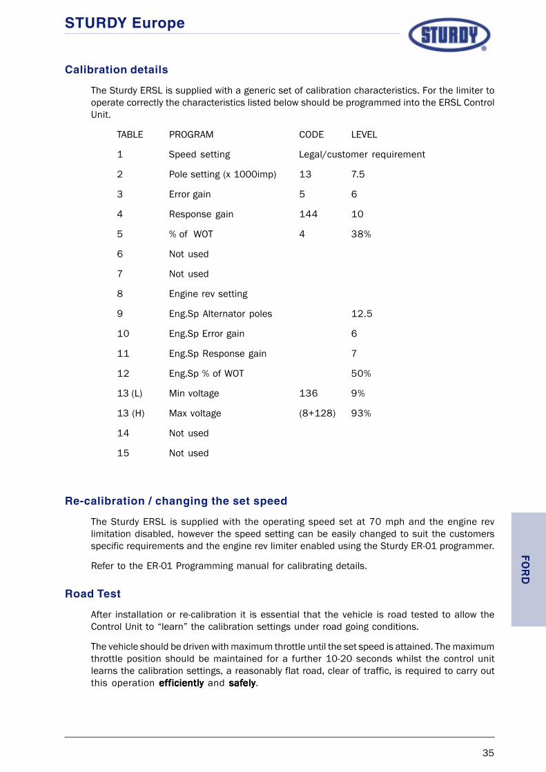
Calibration details
The Sturdy ERSL is supplied with a generic set of calibration characteristics. For the limiter tooperate correctly the characteristics listed below should be programmed into the ERSL ControlUnit.
TABLE PROGRAM CODE LEVEL
1 Speed setting Legal/customer requirement
2 Pole setting (x 1000imp) 13 7.5
3 Error gain 5 6
4 Response gain 144 10
5 % of WOT 4 38%
6 Not used
7 Not used
8 Engine rev setting
9 Eng.Sp Alternator poles 12.5
10 Eng.Sp Error gain 6
11 Eng.Sp Response gain 7
12 Eng.Sp % of WOT 50%
13 (L) Min voltage 136 9%
13 (H) Max voltage (8+128) 93%
14 Not used
15 Not used
Re-calibration / changing the set speed
The Sturdy ERSL is supplied with the operating speed set at 70 mph and the engine revlimitation disabled, however the speed setting can be easily changed to suit the customersspecific requirements and the engine rev limiter enabled using the Sturdy ER-01 programmer.
Refer to the ER-01 Programming manual for calibrating details.
Road Test
After installation or re-calibration it is essential that the vehicle is road tested to allow theControl Unit to “learn” the calibration settings under road going conditions.
The vehicle should be driven with maximum throttle until the set speed is attained. The maximumthrottle position should be maintained for a further 10-20 seconds whilst the control unitlearns the calibration settings, a reasonably flat road, clear of traffic, is required to carry outthis operation efefefefefffffficientlyicientlyicientlyicientlyiciently and safsafsafsafsafelyelyelyelyely.
FOR
DFO
RD
FOR
DFO
RD
FOR
D

STURDY Europe
36
FOR
DFO
RD
FOR
DFO
RD
FOR
D

STURDY Europe
37
STURDY ELECTRONIC ROAD SPEED LIMITER
FITTING INSTRUCTIONS
FOR
FORD TRANSIT 2005
MODELS: From 2005
ERSL KIT No: ER-06
KIT CONTENTS: 57D-03668 Control Unit (pre-set at 70 mph)
57C-03060-005 Wiring Loom
59A-03362 Fitting Accessories
Fitting Instructions
In keeping with good workshop practices the vehicle battery should be disconnected beforeattempting to install the ERSL.
Ensure that any security codes for Radios, Alarms, etc., are available before disconnectingthe battery.
Control Unit
The control unit can be fitted in the area above the glove box compartment using suitablescrews or adhesive. Access is achieved by removing the storage tray in the top of the dashboardin front of the passenger seats.
Wiring Loom
Connect the ERSL wiring loom to the 18pin connector in the Control Unit.
Run the ERSL loom containing 10 wires down to the throttle pedal assembly.
Disconnect the wiring plug at the throttle position potentiometer, remove the protective plasticsleeve and approximately 200mm of canvas wrap from the wiring loom to the potentiometerplug.
Referring to the schematic diagram on page xi, separate the WhiteWhiteWhiteWhiteWhite wire (pin 5) from thepotentiometer loom and cut the wire at a convenient position.
Using the butt splices supplied in the ERSL kit, connect the PurplePurplePurplePurplePurple wire from the ERSL loomto the throttle pedal side of the cut wire. Then connect the BrownBrownBrownBrownBrown wire from the ERSL loomto the ECM side of the cut wire.
FOR
DFO
RD
FOR
DFO
RD
FOR
D

STURDY Europe
38
Wiring Loom cont’d
Separate the White/blueWhite/blueWhite/blueWhite/blueWhite/blue wire (pin 7) from the potentiometer loom, again cutting the wire ata convenient position.
Connect the OrangeOrangeOrangeOrangeOrange wire from the ERSL loom to the pedal side of the cut wire and theYYYYYelloelloelloelloellowwwww wire from the ERSL loom to the ECM side of the cut wire.
Separate the White/redWhite/redWhite/redWhite/redWhite/red (pin 4) wire from the potentiometer loom and cut the wire at aconvenient location.
Connect the Green/yellowGreen/yellowGreen/yellowGreen/yellowGreen/yellow wire from the ERSL loom to the pedal side of the cut wire andthe TTTTTan/redan/redan/redan/redan/red wire from the ERSL loom to the ECM side of the cut wire.
Connect the PinkPinkPinkPinkPink wire from the ERSL loom in series with the Brown/blueBrown/blueBrown/blueBrown/blueBrown/blue wire (pin 2) in thepotentiometer loom.
Connect the Black/yellowBlack/yellowBlack/yellowBlack/yellowBlack/yellow wire from the ERSL loom in series with the Brown/redBrown/redBrown/redBrown/redBrown/red wire (pin6) in the potentiometer loom.
Once the connections have been made wrap the looms with insulating tape to provide a neatfinish and re-connect the loom to the throttle potentiometer.
If the engine rev limitation is required, the BlueBlueBlueBlueBlue wire from the ERSL loom should be routed tothe rear of the speedometer where it should be spliced to the White/blackWhite/blackWhite/blackWhite/blackWhite/black wire from thelarge plug in the rear of the speedometer.
To complete the wiring for the ERSL there are a further three connections to be made, GreenGreenGreenGreenGreenwire to road speed signal, RedRedRedRedRed wire to ignition positive and BlackBlackBlackBlackBlack wire to negative. Wherethese connections should be made will depend on the vehicle having either a tachograph oran electronic speedometer fitted.
Tachograph fitted
The ERSL loom containing the Green, Red and Black wires should be routed to the back ofthe tachograph. Using an appropriate butt-splice connect the RedRedRedRedRed wire to the tachographignition positive (pin A3), connect the BlackBlackBlackBlackBlack wire to the tachograph negative (pin A5). TheGreenGreenGreenGreenGreen wire should be connected to either terminal B7 or D3 in the rear of the tachographcasing.
These actions will normally result in the breaking of a tachograph seal, if the vehicle fallswithin the category of vehicles governed by EC tachograph regulations, this seal must bereplaced by a Dpt of transport approved tachograph calibration centre.
Electronic Speedometer fitted
In cases where an electronic speedometer is fitted to the vehicle, a speed signal for the ERSLcan be obtained at the rear of the speedometer.
At the rear of the speedometer is a small connector plug. The White/ violetWhite/ violetWhite/ violetWhite/ violetWhite/ violet wire in this plugcarries the speed signal from the gearbox transducer, the GreenGreenGreenGreenGreen wire from the ERSL loomshould be spliced to this wire using an appropriate butt-splice.
FOR
DFO
RD
FOR
DFO
RD
FOR
D

STURDY Europe
39
Calibration details
The Sturdy ERSL is supplied with a generic set of calibration characteristics. For the limiter tooperate correctly the characteristics listed below should be programmed into the ERSL ControlUnit.
TABLE PROGRAM CODE LEVEL
1 Speed setting Legal/customer requirement
2 Pole setting (x 1000imp) 13 7.5
3 Error gain 5 6
4 Response gain 144 10
5 % of WOT 4 38%
6 Not used
7 Not used
8 Engine rev setting
9 Eng.Sp Alternator poles 12.5
10 Eng.Sp Error gain 6
11 Eng.Sp Response gain 7
12 Eng.Sp % of WOT 50%
13 (L) Min voltage 136 9%
13 (H) Max voltage (8+128) 93%
14 Not used
15 Not used
Re-calibration / changing the set speed
The Sturdy ERSL is supplied with the operating speed set at 70 mph and the engine revlimitation disabled, however the speed setting can be easily changed to suit the customersspecific requirements and the engine rev limiter enabled using the Sturdy ER-01 programmer.
Refer to the ER-01 Programming manual for calibrating details.
Road Test
After installation or re-calibration it is essential that the vehicle is road tested to allow theControl Unit to “learn” the calibration settings under road going conditions.
The vehicle should be driven with maximum throttle until the set speed is attained. The maximumthrottle position should be maintained for a further 10-20 seconds whilst the control unitlearns the calibration settings, a reasonably flat road, clear of traffic, is required to carry outthis operation efefefefefffffficientlyicientlyicientlyicientlyiciently and safsafsafsafsafelyelyelyelyely.
FOR
DFO
RD
FOR
DFO
RD
FOR
D

STURDY Europe
40
FOR
DFO
RD
FOR
DFO
RD
FOR
D

STURDY Europe
41
STURDY ELECTRONIC ROAD SPEED LIMITER
FITTING INSTRUCTIONS
FOR
ISUZU
MODELS: NPR
ERSL KIT No: ER-02
KIT CONTENTS: 57D-02996 Control Unit (preset at 70 m.p.h.)
57C-03060-002 Wiring Loom
59A-03115 Fitting Accessories
Fitting Instructions
In keeping with good workshop practices the vehicle battery should be disconnected beforeattempting to install the ERSL.
Ensure that any security codes for Radios, Alarms, etc., are available before disconnectingthe battery.
Control Unit
The control unit can be fitted to the left-hand side of the glove box compartment using cableties. Access is achieved by removing the glove box from the dashboard in front of the passengerseats.
Wiring Loom
Remove the Purple and Brown wires from their sheath and cut the wires approximately 200mmfrom the connector, then using a butt splice supplied with the kit join the cut ends of the wirestogether. Feed the joined wires back into the protective sheath.
Connect the ERSL wiring loom to the 18pin connector in the Control Unit.
Run the ERSL loom across the dashboard to a position behind the instrument cluster. At thispoint separate the loom containing the yellow, orange and pink wires and run it down to thethrottle pedal assembly.
Remove 2 x 12mm captive nuts that secure the throttle pedal assembly and remove theassembly.
Referring to the schematic diagram on page xii, separate the Green/yellowGreen/yellowGreen/yellowGreen/yellowGreen/yellow wire from thepotentiometer loom and cut the wire at a convenient position.
ISU
ZUIS
UZU
ISU
ZUIS
UZU
ISU
ZU

STURDY Europe
42
Wiring Loom cont’d
Using the butt splices supplied in the ERSL kit, connect the OrangeOrangeOrangeOrangeOrange wire from the ERSL loomto the throttle pedal side of the cut wire. Then connect the YYYYYelloelloelloelloellowwwww wire from the ERSL loomto the ECM side of the cut wire.
Connect the PinkPinkPinkPinkPink wire from the ERSL loom in series with the Black/greenBlack/greenBlack/greenBlack/greenBlack/green wire in thepotentiometer loom.
Once the connections have been made wrap the looms with insulating tape to provide a neatfinish and re-connect the loom to the throttle potentiometer and re-fit the throttle pedalassembly.
To complete the wiring for the ERSL there are a further three connections to be made, Greenwire to road speed signal, Red wire to ignition positive and Black wire to negative. Theseconnections can all be made at the rear of the instrument cluster.
The ERSL loom containing the Green, Red and Black wires should be routed to the back ofthe instrument cluster. Behind the instrument cluster you will find a spare tachograph wiringconnector (White mini-timer plug). Using an appropriate butt-splice connect the RedRedRedRedRed wire tothe tachograph ignition positive (pin A3), connect the BlackBlackBlackBlackBlack wire to the tachograph negative(pin A5).
The GreenGreenGreenGreenGreen wire should be connected to the terminal post, marked SIG and positioned behindthe speedometer section of the cluster, using a suitable ring terminal.
If engine rev limitation is required then the Blue wire from the ERSL loom should be routed tothe rear of the rev counter side of the instrument cluster where another terminal post markedSIG will be found. Connect the BlueBlueBlueBlueBlue wire to this post using a suitable ring terminal.
ISU
ZUIS
UZU
ISU
ZUIS
UZU
ISU
ZU

STURDY Europe
43
Calibration details
The Sturdy ERSL is supplied with a generic set of calibration characteristics. For the limiter tooperate correctly the characteristics listed below should be programmed into the ERSL ControlUnit.
TABLE PROGRAM CODE LEVEL
1 Speed setting Legal/customer requirement
2 Pole setting (x 1000imp) 6 4
3 Error gain 6 7
4 Response gain 144 10
5 % of WOT 8 52%
6 Not used
7 Not used
8 Engine rev setting
9 Eng.Sp Alternator poles 5
10 Eng.Sp Error gain 7
11 Eng.Sp Response gain 10
12 Eng.Sp % of WOT 50%
13 (L) Min voltage 136 9%
13 (H) Max voltage (8+128) 93%
14 Not used
15 Not used
Re-calibration / changing the set speed
The Sturdy ERSL can be supplied to the customers specification, however the speed settingcan be easily changed to suit new requirements using the Sturdy ER-01 programmer.
Refer to the ER-01 Programming manual for calibrating details.
Road Test
After installation or re-calibration it is essential that the vehicle is road tested to allow theControl Unit to “learn” the calibration settings under road going conditions.
The vehicle should be driven with maximum throttle until the set speed is attained. The maximumthrottle position should be maintained for a further 10-20 seconds whilst the control unitlearns the calibration settings, a reasonably flat road, clear of traffic, is required to carry outthis operation efefefefefffffficientlyicientlyicientlyicientlyiciently and safsafsafsafsafelyelyelyelyely. IS
UZU
ISU
ZUIS
UZU
ISU
ZUIS
UZU

STURDY Europe
44
ISU
ZUIS
UZU
ISU
ZUIS
UZU
ISU
ZU

STURDY Europe
45
STURDY ELECTRONIC ROAD SPEED LIMITER
FITTING INSTRUCTIONS
FOR
ISUZU
MODELS: NQR
ERSL KIT No: ER-02
KIT CONTENTS: 57D-02996 Control Unit (preset at 70 m.p.h.)
57C-03060-002 Wiring Loom
59A-03115 Fitting Accessories
Fitting Instructions
In keeping with good workshop practices the vehicle battery should be disconnected beforeattempting to install the ERSL.
Ensure that any security codes for Radios, Alarms, etc., are available before disconnectingthe battery.
Control Unit
The control unit can be fitted to the left-hand side of the glove box compartment using cableties. Access is achieved by removing the glove box from the dashboard in front of the passengerseats.
Wiring Loom
Connect the ERSL wiring loom to the 18pin connector in the Control Unit.
Run the ERSL loom across the dashboard to a position behind the instrument cluster. At thispoint separate the loom containing the yellow, orange, purple, brown and pink wires and runit down to the throttle pedal assembly.
Referring to the schematic diagram on page xiii, separate the Blue/whiteBlue/whiteBlue/whiteBlue/whiteBlue/white wire from pin 5 inthe potentiometer loom and cut the wire at a convenient position.
Using the butt splices supplied in the ERSL kit, connect the OrangeOrangeOrangeOrangeOrange wire from the ERSL loomto the throttle pedal side of the cut wire. Then connect the YYYYYelloelloelloelloellowwwww wire from the ERSL loomto the ECM side of the cut wire.
Connect the PinkPinkPinkPinkPink wire from the ERSL loom in series with the BlackBlackBlackBlackBlack wire in pin 3 of thepotentiometer loom.
ISU
ZUIS
UZU
ISU
ZUIS
UZU
ISU
ZU

STURDY Europe
46
Wiring Loom cont’d
Separate the WhiteWhiteWhiteWhiteWhite wire from pin 2 in the potentiometer loom and cut the wire at a suitableposition.
Using the butt splices supplied in the ERSL kit, connect the PurplePurplePurplePurplePurple wire from the ERSL loomto the throttle pedal side of the cut wire. Then connect the BrownBrownBrownBrownBrown wire from the ERSL loomto the ECM side of the cut wire.
Once the connections have been made wrap the looms with insulating tape to provide a neatfinish and re-connect the loom to the throttle potentiometer and re-fit the throttle pedalassembly.
To complete the wiring for the ERSL there are a further three connections to be made, Greenwire to road speed signal, Red wire to ignition positive and Black wire to negative. Theseconnections can all be made at the rear of the instrument cluster.
The ERSL loom containing the Green, Red and Black wires should be routed to the back ofthe instrument cluster. Behind the instrument cluster you will find a spare tachograph wiringconnector (White mini-timer plug). Using an appropriate butt-splice connect the RedRedRedRedRed wire tothe tachograph ignition positive (pin A3), connect the BlackBlackBlackBlackBlack wire to the tachograph negative(pin A5).
The GreenGreenGreenGreenGreen wire should be connected to the terminal post, marked SIG and positioned behindthe speedometer section of the cluster, using a suitable ring terminal.
If engine rev limitation is required then the Blue wire from the ERSL loom should be routed tothe rear of the rev counter side of the instrument cluster where another terminal post markedSIG will be found. Connect the BlueBlueBlueBlueBlue wire to this post using a suitable ring terminal.
ISU
ZUIS
UZU
ISU
ZUIS
UZU
ISU
ZU

STURDY Europe
47
Calibration details
The Sturdy ERSL is supplied with a generic set of calibration characteristics. For the limiter tooperate correctly the characteristics listed below should be programmed into the ERSL ControlUnit.
TABLE PROGRAM CODE LEVEL
1 Speed setting Legal/customer requirement
2 Pole setting (x 1000imp) 6 4
3 Error gain 6 7
4 Response gain 144 10
5 % of WOT 8 52%
6 Not used
7 Not used
8 Engine rev setting
9 Eng.Sp Alternator poles 5
10 Eng.Sp Error gain 7
11 Eng.Sp Response gain 10
12 Eng.Sp % of WOT 50%
13 (L) Min voltage 136 9%
13 (H) Max voltage (8+128) 93%
14 Not used
15 Not used
Re-calibration / changing the set speed
The Sturdy ERSL can be supplied to the customers specification, however the speed settingcan be easily changed to suit new requirements using the Sturdy ER-01 programmer.
Refer to the ER-01 Programming manual for calibrating details.
Road Test
After installation or re-calibration it is essential that the vehicle is road tested to allow theControl Unit to “learn” the calibration settings under road going conditions.
The vehicle should be driven with maximum throttle until the set speed is attained. The maximumthrottle position should be maintained for a further 10-20 seconds whilst the control unitlearns the calibration settings, a reasonably flat road, clear of traffic, is required to carry outthis operation efefefefefffffficientlyicientlyicientlyicientlyiciently and safsafsafsafsafelyelyelyelyely.
ISU
ZUIS
UZU
ISU
ZUIS
UZU
ISU
ZU

STURDY Europe
48
ISU
ZUIS
UZU
ISU
ZUIS
UZU
ISU
ZU

STURDY Europe
49
STURDY ELECTRONIC ROAD SPEED LIMITER
FITTING INSTRUCTIONS
FOR
IVECO DAILY
MODELS: EDC .13
ERSL KIT No: ER-02
KIT CONTENTS: 57D-02996 Control Unit (preset at 70 m.p.h.)
57C-03060-002 Wiring Loom
59A-03115 Fitting Accessories
Fitting Instructions
In keeping with good workshop practices the vehicle battery should be disconnected beforeattempting to install the ERSL.
Ensure that any security codes for Radios, Alarms, etc., are available before disconnectingthe battery.
Control Unit
Find a suitable position within the cab of the vehicle and secure the Control Unit, ensuringthat the site is not directly in the air flow from any heater ducts.
Wiring Loom
Remove the Purple and Brown wires from their sheath and cut the wires approximately 200mmfrom the connector, then using a butt splice supplied with the kit join the cut ends of the wirestogether. Feed the joined wires back into the protective sheath.
Connect the ERSL wiring loom to the 18pin connector in the Control Unit.
Select the ERSL loom containing three wires (Red, Black and Green) and run this to the fusepanel / rear of Tachograph / rear of electronic speedometer. Connect the RRRRRededededed wire from theERSL loom to an ignition switched positive. Connect the BlackBlackBlackBlackBlack wire from the ERSL wiringloom to a vehicle ground. Connect the GreenGreenGreenGreenGreen wire from the ERSL loom to the wire carrying aspeed signal.
Route the other half of the ERSL wiring loom to the vehicle wiring harness that runs to thethrottle potentiometer.
IVECO
IVECO
IVECO
IVECO
IVECO
STURDY Europe
50
Wiring Loom cont’d
At a suitable position in the potentiometer wiring harness, separate and cut the OrangeOrangeOrangeOrangeOrange(5157) wire connected to pin 5 of the Throttle Pedal Sensor. Using a butt splice included inthe kit, connect the OrangeOrangeOrangeOrangeOrange wire from the ERSL loom to the cut wire from the throttlepotentiometer (refer to wiring diagram on page xiv).
Connect the YYYYYelloelloelloelloellowwwww wire from the ERSL loom to the cut wire that runs to the vehicle ECU.
Separate the BrBrBrBrBrooooownwnwnwnwn (0150) wire from pin 6 of the potentiometer harness and using a suitableconnector, splice the PinkPinkPinkPinkPink wire from the ERSL loom to it.
Once the connections have been made wrap the looms with insulating tape to provide a neatfinish and reconnect the loom to the throttle potentiometer.
Calibration details
The Sturdy ERSL is supplied with generic calibration characteristics which may or may not besuitable for the vehicle.
For advise on the suitability of the calibration contact the Sturdy Europe Technical Department.
Re-calibration / changing the set speed
The Sturdy ERSL is supplied with the operating speed set at 70 m.p.h., however the speedsetting can be easily changed to suit the customers specific requirements using the SturdyER-01 programmer.
Refer to the ER-01 Programming manual for calibrating details.
Road Test
Although the ERSL is supplied fully calibrated it is essential that, after installation, the vehiclebe road tested to allow the Control Unit to “learn” the calibration settings under road goingconditions. The vehicle should be driven with maximum throttle until the set speed is attained.The maximum throttle position should be maintained for a further 10-20 seconds whilst thecontrol unit learns the calibration settings, a reasonably flat road, clear of traffic, is requiredto carry out this operation efefefefefffffficiently iciently iciently iciently iciently and saf saf saf saf safelyelyelyelyely.....
IVEC
OIV
ECO
IVEC
OIV
ECO
IVEC
O

STURDY Europe
51
STURDY ELECTRONIC ROAD SPEED LIMITER
FITTING INSTRUCTIONS
FOR
LDV Convoy
MODELS: Dura torque (2000)
ERSL KIT No: ER-06
KIT CONTENTS: 57D-03668 Control Unit (pre-set at 70 mph)
57C-03060-005 Wiring Loom
59A-03386 Fitting Accessories
Fitting Instructions
In keeping with good workshop practices the vehicle battery should be disconnected beforeattempting to install the ERSL.
Ensure that any security codes for Radios, Alarms, etc., are available before disconnectingthe battery.
Control Unit
The control unit can be fitted in the area above or below the stowage shelf in the lower,drivers side dash panel, using suitable screws or adhesive.
Wiring Loom
Connect the ERSL wiring loom to the 18pin connector in the Control Unit.
Run the ERSL loom containing 10 wires down to the throttle pedal assembly.
Disconnect the wiring plug at the throttle position potentiometer, remove the protective plasticsleeve and approximately 200mm of canvas wrap from the wiring loom to the potentiometerplug.
Referring to the schematic diagram on page xv, separate the WhitWhitWhitWhitWhite/bluee/bluee/bluee/bluee/blue wire (pin 5) fromthe potentiometer loom and cut the wire at a convenient position.
Using the butt splices supplied in the ERSL kit, connect the PurplePurplePurplePurplePurple wire from the ERSL loomto the throttle pedal side of the cut wire. Then connect the BrownBrownBrownBrownBrown wire from the ERSL loomto the ECM side of the cut wire.
Separate the GreyGreyGreyGreyGrey wire (pin 7) from the potentiometer loom, again cutting the wire at aconvenient position.
LDV
LDV
LDV
LDV
LDV

STURDY Europe
52
Wiring Loom cont’d
Connect the OrangeOrangeOrangeOrangeOrange wire from the ERSL loom to the pedal side of the cut wire and theYYYYYelloelloelloelloellowwwww wire from the ERSL loom to the ECM side of the cut wire.
Separate the WhiteWhiteWhiteWhiteWhite (pin 4) wire from the potentiometer loom and cut the wire at a convenientlocation.
Connect the Green/yellowGreen/yellowGreen/yellowGreen/yellowGreen/yellow wire from the ERSL loom to the pedal side of the cut wire andthe TTTTTan/redan/redan/redan/redan/red wire from the ERSL loom to the ECM side of the cut wire.
Connect the PinkPinkPinkPinkPink wire from the ERSL loom in series with the Purple/yellowPurple/yellowPurple/yellowPurple/yellowPurple/yellow wire (pin 2) inthe potentiometer loom.
Connect the Black/yellowBlack/yellowBlack/yellowBlack/yellowBlack/yellow wire from the ERSL loom in series with the BrownBrownBrownBrownBrown wire (pin 6) inthe potentiometer loom.
Once the connections have been made wrap the looms with insulating tape to provide a neatfinish and re-connect the loom to the throttle potentiometer.
If the engine rev limitation is required, the BlueBlueBlueBlueBlue wire from the ERSL loom should be routed tothe rear of the speedometer were it should be spliced to the White/blackWhite/blackWhite/blackWhite/blackWhite/black wire from thelarge ‘A’ block pin 10.
To complete the wiring for the ERSL there are a further three connections to be made, GreenGreenGreenGreenGreenwire to road speed signal, RedRedRedRedRed wire to ignition positive and BlackBlackBlackBlackBlack wire to negative. Wherethese connections should be made will depend on the vehicle having either a tachograph oran electronic speedometer fitted.
Tachograph fitted
The ERSL loom containing the Green, Red and Black wires should be routed to the back ofthe tachograph. Using an appropriate butt-splice connect the RedRedRedRedRed wire to the tachographignition positive (pin A3), connect the BlackBlackBlackBlackBlack wire to the tachograph negative (pin A5). TheGreenGreenGreenGreenGreen wire should be connected to either terminal B7 or D3 in the rear of the tachographcasing.
These actions will normally result in the breaking of a tachograph seal, if the vehicle fallswithin the category of vehicles governed by EC tachograph regulations, this seal must bereplaced by a Dpt of transport approved tachograph calibration centre.
Electronic Speedometer fitted
In cases where an electronic speedometer is fitted to the vehicle, a speed signal for the ERSLcan be obtained at the rear of the speedometer.
At the rear of the speedometer is a large connector plug ‘A’. The wire in pin 7 of this plugcarries the speed signal from the gearbox transducer, the GreenGreenGreenGreenGreen wire from the ERSL loomshould be spliced to this wire using an appropriate butt-splice.
LDV
LDV
LDV
LDV
LDV

STURDY Europe
53
Calibration details
The Sturdy ERSL is supplied with a generic set of calibration characteristics. For the limiter tooperate correctly the characteristics listed below should be programmed into the ERSL ControlUnit.
TABLE PROGRAM CODE LEVEL
1 Speed setting Legal/customer requirement
2 Pole setting (x 1000imp) 13 7.5
3 Error gain 5 6
4 Response gain 144 10
5 % of WOT 4 38%
6 Not used
7 Not used
8 Engine rev setting
9 Eng.Sp Alternator poles 12.5
10 Eng.Sp Error gain 6
11 Eng.Sp Response gain 7
12 Eng.Sp % of WOT 50%
13 (L) Min voltage 136 9%
13 (H) Max voltage (8+128) 93%
14 Not used
15 Not used
Re-calibration / changing the set speed
The Sturdy ERSL is supplied with the operating speed set at 70 mph and the engine revlimitation disabled, however the speed setting can be easily changed to suit the customersspecific requirements and the engine rev limiter enabled using the Sturdy ER-01 programmer.
Refer to the ER-01 Programming manual for calibrating details.
Road Test
After installation or re-calibration it is essential that the vehicle is road tested to allow theControl Unit to “learn” the calibration settings under road going conditions.
The vehicle should be driven with maximum throttle until the set speed is attained. The maximumthrottle position should be maintained for a further 10-20 seconds whilst the control unitlearns the calibration settings, a reasonably flat road, clear of traffic, is required to carry outthis operation efefefefefffffficientlyicientlyicientlyicientlyiciently and safsafsafsafsafelyelyelyelyely.
LDV
LDV
LDV
LDV
LDV

STURDY Europe
54
LDV
LDV
LDV
LDV
LDV

STURDY Europe
55
STURDY ELECTRONIC ROAD SPEED LIMITER
FITTING INSTRUCTIONS
FOR
MERCEDES-BENZ SPRINTER
MODELS: 210D, 212D, 310D, 312D, 410D, and 412D
ERSL KIT No: ER-02
KIT CONTENTS:
57D-02996 Control Unit (preset at 70 m.p.h.)
57C-03060-002 Wiring Loom
59A-03386 Fitting Accessories
FITTING INSTRUCTIONS
In keeping with good workshop practices the vehicle battery should be disconnected beforeattempting to install the ERSL.
Ensure that any security codes for Radios, Alarms, etc., are available before disconnectingthe battery.
Control Unit
To allow easy access when siting the ERSL Control Unit it is recommended that the near sideheadlamp assembly be removed.
Using the Control Unit base plate as a template mark the positions of the four fixing holesonto the flat panel between the nearside wheel arch and the front panel of the vehicle directlybelow the headlamp.
Drill 4 x M6 clearance holes, and install the Control Unit using M6 bolts, spacing bushes, nutsand washers (see diagram on page 58). The spacers are used to keep the control unit aboveany water that may collect on the panel where it is fitted.
The Control Unit should be mounted with the electrical connection socket facing the nearside wing of the vehicle.
Wiring Loom
Before connecting the wring loom to the ERSL Control Unit the loom must be modified.
Remove the Green wire from its sheath and install it into the sheath housing the Red andBlack wires.
If control of Engine revs is NOT required then cut the blue wire in such a position that it nolonger protrudes from it’s protective sheath (always tape the cut end).
MER
CED
ES-BEN
ZM
ERC
EDES-B
ENZ
MER
CED
ES-BEN
ZM
ERC
EDES-B
ENZ
MER
CED
ES-BEN
Z

STURDY Europe
56
Wiring Loom cont’d
Remove the Purple and Brown wires from their sheath and cut the wires approximately 200mmfrom the connector, then using a butt splice supplied with the kit join the cut ends of the wirestogether. Feed the joined wires back into the protective sheath.
Connect the ERSL wiring loom to the 18 pin connector in the Control Unit.
Run both sections of the ERSL loom along the main wiring loom for the vehicles ElectronicControl Module (ECM) until it reaches the point where the ECM loom splits. One part of theECM loom runs toward the throttle position potentiometer, the other part being routed throughthe engine bulkhead into the cab of the vehicle following the main wiring bundle.
Select the half of the ERSL loom containing three wires (Red, Black and Green) and run thisthrough the bulkhead access port into the cab of the vehicle (a wire threader will be requiredfor this operation).
The other half of the ERSL wiring loom should follow the routing of the Throttle positionpotentiometer wiring.
At the Throttle potentiometer, disconnect the vehicle wiring from the potentiometer and usingan appropriate tool remove approximately 150 mm of canvas wrap from the wiring loom.
Referring to the schematic diagram on page xvi, separate the WhiteWhiteWhiteWhiteWhite wire (pin 5) from thepotentiometer loom and cut the wire at a convenient position.
Using the butt splices supplied in the ERSL kit, connect the OrangeOrangeOrangeOrangeOrange wire from the ERSL loomto the throttle pedal side of the cut wire. Then connect the YYYYYelloelloelloelloellowwwww wire from the ERSL loomto the ECM side of the cut wire.
Connect the PinkPinkPinkPinkPink wire from the ERSL loom in series with the YYYYYelloelloelloelloellowwwww wire (pin 6) in thepotentiometer loom.
Once the connections have been made wrap the looms with insulating tape to provide a neatfinish and reconnect the loom to the throttle potentiometer.
Secure the ERSL loom to the vehicle wiring using cable ties.
The other half of the ERSL loom (Red, Black and Green wires) should now be routed behindthe dashboard (over the transmission tunnel and the steering column support struts), to thewiring bundle situated behind the lower dashboard panel to the right of the steering column(see diagram on page 59).
Crimp the ring terminal supplied to the BlackBlackBlackBlackBlack (negative) lead in the ERSL loom and connect tothe cab earth point in the driver’s foot well.
Locate the speedometer signal generator lead and disconnect the two-pin plug.
Using a suitable tool remove approximately 200mm of the cable outer covering, splice theGreenGreenGreenGreenGreen wire from the ERSL loom together with the signal wire (whitewhitewhitewhitewhite) from the generatorusing the butt splice supplied and refit the two halves of the plug (see page 59).
Locate and separate from its wiring bundle the positive wire (white/redwhite/redwhite/redwhite/redwhite/red) to the brake lights,splice the RedRedRedRedRed (positive) lead from the ERSL loom to this wire using the butt splice supplied.
MER
CED
ES-B
ENZ
MER
CED
ES-B
ENZ
MER
CED
ES-B
ENZ
MER
CED
ES-B
ENZ
MER
CED
ES-B
ENZ

STURDY Europe
57
Calibration details
The Sturdy ERSL is supplied with a generic set of calibration characteristics. For the limiter tooperate correctly the characteristics listed below should be programmed into the ERSL ControlUnit.
TABLE PROGRAM CODE LEVEL
1 Speed setting Legal/customer requirement
2 Pole setting (x 1000imp) 24 13
3 Error gain 6 7
4 Response gain 144 10
5 % of WOT 8 52%
6 Not used
7 Not used
8 Engine rev setting
9 Eng.Sp Alternator poles 17
10 Eng.Sp Error gain 9
11 Eng.Sp Response gain 1
12 Eng.Sp % of WOT 36%
13 (L) Min. voltage 136 9%
13 (H) Max voltage (8+128) 93%
14 Not used
15 Not used
When fitted to 310 and 410 models it will be necessary to engage the “ High Torque Option”.See ER-01 Programming Manual for details.
Re-calibration / changing the set speed
The Sturdy ERSL is supplied with the operating speed set at 70 m.p.h., however the speedsetting can be easily changed to suit the customers specific requirements using the SturdyER-01 programmer.
Refer to the ER-01 Programming manual for calibrating details.
Road Test
Although the ERSL is supplied fully calibrated it is essential that, after installation, the vehiclebe road tested to allow the Control Unit to “learn” the calibration settings under road goingconditions. The vehicle should be driven with maximum throttle until the set speed is attained.The maximum throttle position should be maintained for a further 10-20 seconds whilst thecontrol unit learns the calibration settings, a reasonably flat road, clear of traffic, is requiredto carry out this operation efefefefefffffficiently and saficiently and saficiently and saficiently and saficiently and safelyelyelyelyely.....
MER
CED
ES-BEN
ZM
ERC
EDES-B
ENZ
MER
CED
ES-BEN
ZM
ERC
EDES-B
ENZ
MER
CED
ES-BEN
Z
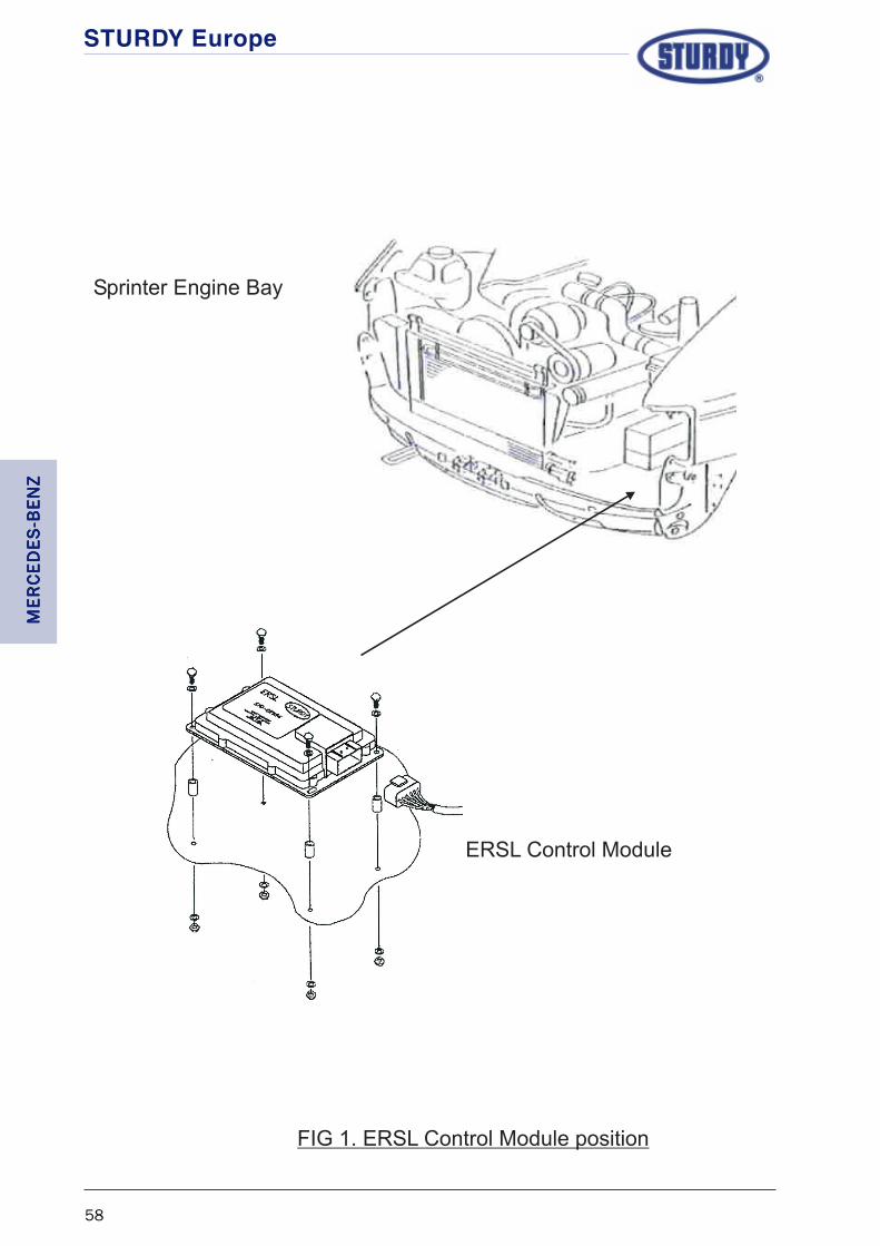
STURDY Europe
58
ERSL Control Module
Sprinter Engine Bay
FIG 1. ERSL Control Module position
MER
CED
ES-B
ENZ
MER
CED
ES-B
ENZ
MER
CED
ES-B
ENZ
MER
CED
ES-B
ENZ
MER
CED
ES-B
ENZ
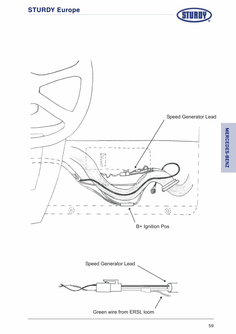
STURDY Europe
59
Speed Generator Lead
Speed Generator Lead
B+ Ignition Pos
Green wire from ERSL loom
MER
CED
ES-BEN
ZM
ERC
EDES-B
ENZ
MER
CED
ES-BEN
ZM
ERC
EDES-B
ENZ
MER
CED
ES-BEN
Z

STURDY Europe
60
MER
CED
ES-B
ENZ
MER
CED
ES-B
ENZ
MER
CED
ES-B
ENZ
MER
CED
ES-B
ENZ
MER
CED
ES-B
ENZ

STURDY Europe
61
STURDY ELECTRONIC ROAD SPEED LIMITER
FITTING INSTRUCTIONS
FOR
MITSUBISHI CANTER
MODELS: Canter
ERSL KIT No: ER-06
KIT CONTENTS: 57D-03668 Control Unit (preset at 70 m.p.h.)
57C-03060-005 Wiring Loom
59A-03386 Fitting Accessories
Fitting Instructions
In keeping with good workshop practices the vehicle battery should be disconnected beforeattempting to install the ERSL.
Ensure that any security codes for Radios, Alarms, etc., are available before disconnectingthe battery.
Control Unit
Find a suitable position within the cab of the vehicle and secure the Control Unit, ensuringthat the site is not directly in the air flow from any heater ducts.
Wiring Loom
Remove the Purple and Brown wires from their sheath and cut the wires approximately 200mmfrom the connector, then using a butt splice supplied with the kit join the cut ends of the wirestogether. Feed the joined wires back into the protective sheath.
Connect the ERSL wiring loom to the 18pin connector in the Control Unit.
Select the ERSL loom containing three wires (Red, Black and Green) and run this to the fusepanel / rear of Tachograph / rear of electronic speedometer. Connect the RRRRRededededed wire from theERSL loom to an ignition switched positive. Connect the BlackBlackBlackBlackBlack wire from the ERSL wiringloom to a vehicle ground. Connect the GreenGreenGreenGreenGreen wire from the ERSL loom to the wire carrying aspeed signal.
Route the other half of the ERSL wiring loom to the vehicle wiring harness that runs to thethrottle potentiometer.
MITSU
BISH
IM
ITSUB
ISHI
MITSU
BISH
IM
ITSUB
ISHI
MITSU
BISH
I

STURDY Europe
62
Wiring Loom cont’d
At a suitable position in the potentiometer wiring harness, separate and cut the Green/blueGreen/blueGreen/blueGreen/blueGreen/bluewire. Using a butt splice included in the kit, connect the OrangeOrangeOrangeOrangeOrange wire from the ERSL loom tothe cut wire from the throttle potentiometer (refer to wiring diagram on page xvii).
Connect the YYYYYelloelloelloelloellowwwww wire from the ERSL loom to the cut wire that runs to the vehicle ECU.
Separate and cut the BlueBlueBlueBlueBlue wire in the potentiometer harness. Using a butt splice included inthe kit, connect the Green/yellowGreen/yellowGreen/yellowGreen/yellowGreen/yellow wire from the ERSL loom to the cut wire from the throttlepotentiometer.
Connect the TTTTTan/redan/redan/redan/redan/red wire from the ERSL loom to the cut wire that runs to the vehicle ECU.
Separate the Green/redGreen/redGreen/redGreen/redGreen/red wire from the potentiometer harness and using a suitable connector,splice the PinkPinkPinkPinkPink and Black/yellowBlack/yellowBlack/yellowBlack/yellowBlack/yellow wires from the ERSL loom to it.
Once the connections have been made wrap the looms with insulating tape to provide a neatfinish and reconnect the loom to the throttle potentiometer.
Calibration details
The Sturdy ERSL is supplied with a generic set of calibration characteristics. For the limiter tooperate correctly the characteristics listed below should be programmed into the ERSL ControlUnit.
TABLE PROGRAM CODE LEVEL
1 Speed setting Legal/customer requirement
2 Pole setting (x 1000imp) 14 8
3 Error gain 6 7
4 Response gain 144 10
5 % of WOT 4 38%
6 Not used
7 Not used
8 Engine rev setting
9 Eng.Sp Alternator poles
10 Eng.Sp Error gain
11 Eng.Sp Response gain
12 Eng.Sp % of WOT
13 (L) Min. voltage 136 9%
13 (H) Max voltage (8+128) 93%
14 Not used
15 Not used
MIT
SUB
ISH
IM
ITSU
BIS
HI
MIT
SUB
ISH
IM
ITSU
BIS
HI
MIT
SUB
ISH
I

STURDY Europe
63
Re-calibration / changing the set speed
The Sturdy ERSL is supplied with the operating speed set at 70 m.p.h., however the speedsetting can be easily changed to suit the customers specific requirements using the SturdyER-01 programmer.
Refer to the ER-01 Programming manual for calibrating details.
Road Test
Although the ERSL is supplied fully calibrated it is essential that, after installation, the vehiclebe road tested to allow the Control Unit to “learn” the calibration settings under road goingconditions. The vehicle should be driven with maximum throttle until the set speed is attained.The maximum throttle position should be maintained for a further 10-20 seconds whilst thecontrol unit learns the calibration settings, a reasonably flat road, clear of traffic, is requiredto carry out this operation efefefefefffffficiently iciently iciently iciently iciently and saf saf saf saf safelyelyelyelyely.....
MITSU
BISH
IM
ITSUB
ISHI
MITSU
BISH
IM
ITSUB
ISHI
MITSU
BISH
I

STURDY Europe
64
MIT
SUB
ISH
IM
ITSU
BIS
HI
MIT
SUB
ISH
IM
ITSU
BIS
HI
MIT
SUB
ISH
I

STURDY Europe
65
STURDY ELECTRONIC ROAD SPEED LIMITER
FITTING INSTRUCTIONS
FOR
PEUGEOT BOXER
MODELS: SWB
ERSL KIT No: ER-07
KIT CONTENTS: 57D-03668 Control Unit (preset at 70 m.p.h.)
57C-03060-005 Wiring Loom
59A-03386 Fitting Accessories
FITTING INSTRUCTIONS
In keeping with good workshop practices the vehicle battery should be disconnected beforeattempting to install the ERSL.
Ensure that any security codes for Radios, Alarms, etc., are available before disconnectingthe battery.
Control Unit
The control unit can be fitted in the area below the drivers side of the dash panel, usingsuitable screws or adhesive.
Wiring Loom
Connect the ERSL wiring loom to the 18pin connector in the Control Unit.
Run the ERSL wiring loom containing 10 wires to the throttle pedal assembly.
Disconnect the wiring plug at the throttle position potentiometer, remove the protective plasticsleeve and approximately 200mm of canvas wrap from the wiring loom to the potentiometerplug.
Refering to the diagram on page xviii, separate the Brown/blackBrown/blackBrown/blackBrown/blackBrown/black wire from the potentiometerloom and cut the wire at a convenient position. Using the butt splices supplied in the ERSL kit,connect the Green/yellowGreen/yellowGreen/yellowGreen/yellowGreen/yellow wire from the ERSL loom to the throttle pedal side of the cutwire, then connect the TTTTTan/redan/redan/redan/redan/red wire from the ERSL loom to the EMC side of the cut wire.
Separate the Blue/blackBlue/blackBlue/blackBlue/blackBlue/black wire from the potentiometer loom and again cut the wire at aconvenient position. Using the butt splices supplied connect the OrangeOrangeOrangeOrangeOrange wire from the ERSLloom to the throttle pedal side of the cut wire, then connect the YYYYYelloelloelloelloellowwwww wire from the ERSLloom to the EMC side of the cut wire.
PEUG
EOT
PEUG
EOT
PEUG
EOT
PEUG
EOT
PEUG
EOT

STURDY Europe
66
Wiring Loom cont’d
Connect the PinkPinkPinkPinkPink wire from the ERSL loom, in series, to the Brown/whiteBrown/whiteBrown/whiteBrown/whiteBrown/white wire in thepotentiometer loom. Connect the Black/yellowBlack/yellowBlack/yellowBlack/yellowBlack/yellow wire from the ERSL loom, in series, with thePurple/blackPurple/blackPurple/blackPurple/blackPurple/black wire in the potentiometer loom.
Once the connections have been made wrap the looms with insulating tape to provide a neatfinish and reconnect the loom to the throttle potentiometer.
If engine rev limitation is required, the BlueBlueBlueBlueBlue wire from the ERSL wiring loom should be routedto the alternator and connected to the W terminal.
To complete the wiring for the ERSL there are a further three connections to be made, thesebeing the Red, Black and Green wires from the ERSL wiring loom. Where these connectionsshould be made will depend on the vehicle having either a tachograph or an electronicspeedometer fitted.
Tachograph fitted
Select the ERSL loom containing three wires (Red, Black and Green) and run this to the rearof the tachograph. At this point, using the butt splices supplied, connect the BlackBlackBlackBlackBlack wire inthe ERSL loom to the tachograph negative (pin A5). The RedRedRedRedRed wire in the ERSL loom is connectedto the ignition switched positive (pin A3) and the GreenGreenGreenGreenGreen wire to the road speed signal ateither pin B7 or pin D3.
If these actions result in the breaking of a tachograph seal, the seal must be replaced by aDepartment of Transport approved tachograph calibration centre.
Electronic Speedometer fitted
At the rear of the speedometer can be found a Black plug containing an Green/greyGreen/greyGreen/greyGreen/greyGreen/grey wire,the GreenGreenGreenGreenGreen wire from the ERSL loom should be spliced to this wire to obtain a road speedsignal. The Red and Black wires from the ERSL loom should be routed to the Brake PedalSwitch where the BlackBlackBlackBlackBlack wire should be spliced to the Negative wire from the switch and theRedRedRedRedRed wire spliced to the Ignition Positive wire to the switch.
PEU
GEO
TPE
UG
EOT
PEU
GEO
TPE
UG
EOT
PEU
GEO
T

STURDY Europe
67
Calibration details
The Sturdy ERSL is supplied with a generic set of calibration characteristics. For the limiter tooperate correctly the characteristics listed below should be programmed into the ERSL ControlUnit.
TABLE PROGRAM CODE LEVEL
1 Speed setting Legal/customer requirement
2 Pole setting (x 1000imp) 13 7.5
3 Error gain 8 9
4 Response gain 176 12
5 % of WOT 8 52%
6 Not used
7 Not used
8 Engine rev setting
9 Eng.Sp Alternator poles 2.5
10 Eng.Sp Error gain 6
11 Eng.Sp Response gain 7
12 Eng.Sp % of WOT 50%
13 (L) Min. voltage 136 9%
13 (H) Max voltage (8+128) 93%
14 Not used
15 Not used
Re-calibration / changing the set speed
The Sturdy ERSL is supplied with the operating speed set at 70 m.p.h., however the speedsetting can be easily changed to suit the legal or customers specific requirements using theSturdy ER-01 programmer.
Refer to the ER-01 Programming manual for programming details.
Road Test
Although the ERSL is supplied fully calibrated it is essential that, after installation, the vehiclebe road tested to allow the Control Unit to “learn” the calibration settings under road goingconditions. The vehicle should be driven with maximum throttle until the set speed is attained.The maximum throttle position should be maintained for a further 10-20 seconds whilst thecontrol unit learns the calibration settings, a reasonably flat road, clear of traffic, is requiredto carry out this operation efefefefefffffficiently iciently iciently iciently iciently and saf saf saf saf safelyelyelyelyely.....
PEUG
EOT
PEUG
EOT
PEUG
EOT
PEUG
EOT
PEUG
EOT

STURDY Europe
68
PEU
GEO
TPE
UG
EOT
PEU
GEO
TPE
UG
EOT
PEU
GEO
T

STURDY Europe
69
STURDY ELECTRONIC ROAD SPEED LIMITER
FITTING INSTRUCTIONS
FOR
RENAULT MASTER
MODELS: All models
ERSL KIT No: ER-07
KIT CONTENTS: 57D-03668 Control Unit (preset at 70 m.p.h.)
57C-03060-005 Wiring Loom
59A-03386 Fitting Accessories
FITTING INSTRUCTIONS
In keeping with good workshop practices the vehicle battery should be disconnected beforeattempting to install the ERSL.
Ensure that any security codes for Radios, Alarms, etc., are available before disconnectingthe battery.
Control Unit
The control unit can be fitted in the area below the drivers side of the dash panel, usingsuitable screws or adhesive.
Wiring Loom
Connect the ERSL wiring loom to the 18pin connector in the Control Unit.
Run the ERSL wiring loom containing 10 wires to the throttle pedal assembly.
Disconnect the wiring plug at the throttle position potentiometer, remove the protective plasticsleeve and approximately 200mm of canvas wrap from the wiring loom to the potentiometerplug.
Refering to the diagram on page xix, separate the YYYYYelloelloelloelloellowwwww wire (pin 6) from the potentiometerloom and cut the wire at a convenient position. Using the butt splices supplied in the ERSL kit,connect the Green/yellowGreen/yellowGreen/yellowGreen/yellowGreen/yellow wire from the ERSL loom to the throttle pedal side of the cutwire, then connect the TTTTTan/redan/redan/redan/redan/red wire from the ERSL loom to the EMC side of the cut wire.
Separate the PinkPinkPinkPinkPink wire (pin 3) from the potentiometer loom and again cut the wire at aconvenient position. Using the butt splices supplied connect the OrangeOrangeOrangeOrangeOrange wire from the ERSLloom to the throttle pedal side of the cut wire, then connect the Yellow wire from the ERSLloom to the EMC side of the cut wire.
RE
NA
RE
NA
RE
NA
RE
NA
RE
NAU
LU
LU
LU
LU
LTT TTT

STURDY Europe
70
Wiring Loom cont’d
Connect the PinkPinkPinkPinkPink wire from the ERSL loom, in series, to the PurplePurplePurplePurplePurple wire (pin 1) in thepotentiometer loom. Connect the Black/yellowBlack/yellowBlack/yellowBlack/yellowBlack/yellow wire from the ERSL loom, in series, with theBrownBrownBrownBrownBrown wire (pin 2) in the potentiometer loom.
Once the connections have been made wrap the looms with insulating tape to provide a neatfinish and reconnect the loom to the throttle potentiometer.
To complete the wiring for the ERSL there are a further three connections to be made, thesebeing the Red, Black and Green wires from the ERSL wiring loom. Where these connectionsshould be made will depend on the vehicle having either a tachograph or an electronicspeedometer fitted.
Tachograph fitted
Select the ERSL loom containing three wires (Red, Black and Green) and run this to the rearof the tachograph. At this point, using the butt splices supplied, connect the BlackBlackBlackBlackBlack wire inthe ERSL loom to the tachograph negative (pin A5). The RedRedRedRedRed wire in the ERSL loom is connectedto the ignition switched positive (pin A3) and the GreenGreenGreenGreenGreen wire to the road speed signal ateither pin B7 or pin D3.
If these actions result in the breaking of a tachograph seal, the seal must be replaced by aDepartment of Transport approved tachograph calibration centre.
Electronic Speedometer fitted
At the rear of the speedometer can be found a Green plug containing an OrangeOrangeOrangeOrangeOrange wire (pin 1)the GreenGreenGreenGreenGreen wire from the ERSL loom should be spliced to this wire to obtain a road speedsignal. The Red and Black wires from the ERSL loom should be routed to the Brake PedalSwitch where the BlackBlackBlackBlackBlack wire should be spliced to the Negative wire from the switch and theRedRedRedRedRed wire spliced to the Ignition Positive wire to the switch.
RE
NA
RE
NA
RE
NA
RE
NA
RE
NA U
LU
LU
LU
LU
L TTTT T

STURDY Europe
71
Calibration details
The Sturdy ERSL is supplied with a generic set of calibration characteristics. For the limiter tooperate correctly the characteristics listed below should be programmed into the ERSL ControlUnit.
TABLE PROGRAM CODE LEVEL
1 Speed setting Legal/customer requirement
2 Pole setting (x 1000imp) 13 7.5
3 Error gain 7 8
4 Response gain 160 11
5 % of WOT 8 52%
6 Not used
7 Not used
8 Engine rev setting
9 Eng.Sp Alternator poles 2.5
10 Eng.Sp Error gain 6
11 Eng.Sp Response gain 7
12 Eng.Sp % of WOT 50%
13 (L) Min. voltage 136 9%
13 (H) Max voltage (8+128) 93%
14 Not used
15 Not used
Re-calibration / changing the set speed
The Sturdy ERSL is supplied with the operating speed set at 70 m.p.h., however the speedsetting can be easily changed to suit the legal or customers specific requirements using theSturdy ER-01 programmer.
Refer to the ER-01 Programming manual for programming details.
Road Test
Although the ERSL is supplied fully calibrated it is essential that, after installation, the vehiclebe road tested to allow the Control Unit to “learn” the calibration settings under road goingconditions. The vehicle should be driven with maximum throttle until the set speed is attained.The maximum throttle position should be maintained for a further 10-20 seconds whilst thecontrol unit learns the calibration settings, a reasonably flat road, clear of traffic, is requiredto carry out this operation efefefefefffffficiently iciently iciently iciently iciently and saf saf saf saf safelyelyelyelyely..... R
EN
AR
EN
AR
EN
AR
EN
AR
EN
AUL
UL
UL
UL
ULTT TTT

STURDY Europe
72
RE
NA
RE
NA
RE
NA
RE
NA
RE
NA U
LU
LU
LU
LU
L TTTT T

STURDY Europe
73
VV VVVAA AAAUXH
ALLU
XHALL
UXH
ALLU
XHALL
UXH
ALL
STURDY ELECTRONIC ROAD SPEED LIMITER
FITTING INSTRUCTIONS
FOR
VAUXHALL ASTRA
MODELS:
ERSL KIT No: ER-07
KIT CONTENTS: 57D-03668 Control Unit (preset at 70 m.p.h.)
57C-03060-005 Wiring Loom
59A-03386 Fitting Accessories
ADDITIONAL EQUIPMENT
122000 SPAL CAN Interface
FITTING INSTRUCTIONS
In keeping with good workshop practices the vehicle battery should be disconnected beforeattempting to install the ERSL.
Ensure that any security codes for Radios, Alarms, etc., are available before disconnectingthe battery.
Control Unit
The control unit can be fitted inside of the transmission tunnel towards the front of thevehicle.
CAN Interface
The interface is fitted next to the ODC connector housed in the transmission tunnel justbelow the hand-brake lever.
Refer to the manufacturers fitting instructions (supplied with the CAN interface), for detailsof the interface wiring.
The Ignition positive feed and the ground for the interface and the ERSL can be located nextto the ODC connector.

STURDY Europe
74
Wiring Loom
Remove the Purple and Brown wires from the ERSL wiring loom, cut the wires approximately100mm from the connector then join the two wire together using one of the butt splicessupplied with the ERSL kit.
Disconnect the wiring plug at the throttle position potentiometer. Refering to the diagram onpage xx, separate the YYYYYelloelloelloelloellow/whitw/whitw/whitw/whitw/whiteeeee wire (pin 3) from the potentiometer loom and cut thewire at a convenient position. Using the butt splices supplied in the ERSL kit, connect theOrangeOrangeOrangeOrangeOrange wire from the ERSL loom to the throttle pedal side of the cut wire, then connect theYYYYYelloelloelloelloellowwwww wire from the ERSL loom to the EMC side of the cut wire.
Separate the Green/whiteGreen/whiteGreen/whiteGreen/whiteGreen/white wire (pin 6) from the potentiometer loom and again cut the wireat a convenient position. Using the butt splices supplied connect the Green/yellowGreen/yellowGreen/yellowGreen/yellowGreen/yellow wirefrom the ERSL loom to the throttle pedal side of the cut wire, then connect the TTTTTan/redan/redan/redan/redan/red wirefrom the ERSL loom to the EMC side of the cut wire.
Connect the PinkPinkPinkPinkPink and the Black/yellowBlack/yellowBlack/yellowBlack/yellowBlack/yellow wires from the ERSL loom, in series, to the Red/Red/Red/Red/Red/brownbrownbrownbrownbrown wire (pin 2) in the potentiometer loom.
Once the connections have been made wrap the looms with insulating tape to provide a neatfinish and reconnect the loom to the throttle potentiometer.
To complete the wiring for the ERSL there are a further three connections to be made, thesebeing the Red, Black and Green wires from the ERSL wiring loom.
The GreenGreenGreenGreenGreen wire from the ERSL loom should be butt spliced to the OrangeOrangeOrangeOrangeOrange wire from the CANinterface to obtain a road speed signal. The RedRedRedRedRed wire from the ERSL loom should be routedto the Brake Pedal Switch and spliced to the Ignition Positive wire to the switch. The BlackBlackBlackBlackBlackwire should have a ring terminal fitted to it and anchored under one of the steering columnsecuring bolts.
VVVV V AAAA AU
XHAL
LU
XHAL
LU
XHAL
LU
XHAL
LU
XHAL
L

STURDY Europe
75
VV VVVAA AAAUXH
ALLU
XHALL
UXH
ALLU
XHALL
UXH
ALL
Calibration details
The Sturdy ERSL is supplied with a generic set of calibration characteristics. For the limiter tooperate correctly the characteristics listed below should be programmed into the ERSL ControlUnit.
TABLE PROGRAM CODE LEVEL
1 Speed setting Legal/customer requirement (less 3%)
2 Pole setting (x 1000imp) 5 3.5
3 Error gain 7 8
4 Response gain 160 11
5 % of WOT 8 52%
6 Not used
7 Not used
8 Speed hold 0 Disabled
9 Not used 0
10 Eng.Sp Error gain 9 10
11 Eng.Sp Response gain 112 8
12 Eng.Sp % of WOT 8 36%
13 (L) Min. voltage 136 9%
13 (H) Max voltage (8+128) 93%
14 Not used
15 Not used
Re-calibration / changing the set speed
The Sturdy ERSL is supplied with the operating speed set at 70 m.p.h., however the speedsetting can be easily changed to suit the legal or customers specific requirements using theSturdy ER-01 programmer.
Refer to the ER-01 Programming manual for programming details.
Road Test
Although the ERSL is supplied fully calibrated it is essential that, after installation, the vehiclebe road tested to allow the Control Unit to “learn” the calibration settings under road goingconditions. The vehicle should be driven with maximum throttle until the set speed is attained.The maximum throttle position should be maintained for a further 10-20 seconds whilst thecontrol unit learns the calibration settings, a reasonably flat road, clear of traffic, is requiredto carry out this operation efefefefefffffficiently iciently iciently iciently iciently and saf saf saf saf safelyelyelyelyely.....

STURDY Europe
76
VVVV V AAAA AU
XHAL
LU
XHAL
LU
XHAL
LU
XHAL
LU
XHAL
L

STURDY Europe
77
STURDY ELECTRONIC ROAD SPEED LIMITER
FITTING INSTRUCTIONS
FOR
VAUXHALL COMBO
MODELS: CDTi
ERSL KIT No: ER-07
KIT CONTENTS: 57D-03668 Control Unit (preset at 70 m.p.h.)
57C-03060-005 Wiring Loom
59A-03386 Fitting Accessories
ADDITIONAL EQUIPMENT
122000 Spal CAN Interface
FITTING INSTRUCTIONS
In keeping with good workshop practices the vehicle battery should be disconnected beforeattempting to install the ERSL.
Ensure that any security codes for Radios, Alarms, etc., are available before disconnectingthe battery.
Control Unit
The control unit can be fitted behind the dashboard to the right of the steering column, usingsuitable screws, cable ties or adhesive.
CAN Interface
Remove the instrument cluster to gain access to the wiring plug at the rear of the cluster.Refer to the manufacturers fitting instructions (supplied with the CAN interface), for detailsof the interface wiring.
The Ignition positive feed for the interface and the ERSL positive feed are connected to thepositive to the brake light switch.The ground wires of the interface and the ERSL can betwinned and connected to a securing bolt for the steering column.
VV VVVAA AAAUXH
ALLU
XHALL
UXH
ALLU
XHALL
UXH
ALL

STURDY Europe
78
Wiring Loom
Remove the Purple and Brown wires from the ERSL wiring loom, cut the wires approximately100mm from the connector then join the two wire together using one of the butt splicessupplied with the ERSL kit.
Disconnect the wiring plug at the throttle position potentiometer. Refering to the diagram onpage xxi, separate the YYYYYelloelloelloelloellow/whitw/whitw/whitw/whitw/whiteeeee wire (pin 3) from the potentiometer loom and cut thewire at a convenient position. Using the butt splices supplied in the ERSL kit, connect theOrangeOrangeOrangeOrangeOrange wire from the ERSL loom to the throttle pedal side of the cut wire, then connect theYYYYYelloelloelloelloellowwwww wire from the ERSL loom to the EMC side of the cut wire.
Separate the Green/whiteGreen/whiteGreen/whiteGreen/whiteGreen/white wire (pin 6) from the potentiometer loom and again cut the wireat a convenient position. Using the butt splices supplied connect the Green/yellowGreen/yellowGreen/yellowGreen/yellowGreen/yellow wirefrom the ERSL loom to the throttle pedal side of the cut wire, then connect the TTTTTan/redan/redan/redan/redan/red wirefrom the ERSL loom to the EMC side of the cut wire.
Connect the PinkPinkPinkPinkPink wire from the ERSL loom, in series, to the Blue/brownBlue/brownBlue/brownBlue/brownBlue/brown wire (pin 2) in thepotentiometer loom. Connect the Black/yellowBlack/yellowBlack/yellowBlack/yellowBlack/yellow wire from the ERSL loom, in series, with theRed/brownRed/brownRed/brownRed/brownRed/brown wire (pin 1) in the potentiometer loom.
Once the connections have been made wrap the looms with insulating tape to provide a neatfinish and reconnect the loom to the throttle potentiometer.
To complete the wiring for the ERSL there are a further three connections to be made, thesebeing the Red, Black and Green wires from the ERSL wiring loom.
The GreenGreenGreenGreenGreen wire from the ERSL loom should be butt spliced to the OrangeOrangeOrangeOrangeOrange wire from the CANinterface to obtain a road speed signal. The Red wire from the ERSL loom should be routed tothe Brake Pedal Switch and spliced to the Ignition Positive wire to the switch. The BlackBlackBlackBlackBlack wireshould have a ring terminal fitted to it and anchored under one of the steering column securingbolts.
VVVV V AAAA AU
XHAL
LU
XHAL
LU
XHAL
LU
XHAL
LU
XHAL
L

STURDY Europe
79
Calibration details
The Sturdy ERSL is supplied with a generic set of calibration characteristics. For the limiter tooperate correctly the characteristics listed below should be programmed into the ERSL ControlUnit.
TABLE PROGRAM CODE LEVEL
1 Speed setting Legal/customer requirement (less 3%)
2 Pole setting (x 1000imp) 5 3.5
3 Error gain 7 8
4 Response gain 160 11
5 % of WOT 8 52%
6 Not used
7 Not used
8 Speed hold 0 Disabled
9 Not used 0
10 Eng.Sp Error gain 9 10
11 Eng.Sp Response gain 112 8
12 Eng.Sp % of WOT 8 36%
13 (L) Min. voltage 136 9%
13 (H) Max voltage (8+128) 93%
14 Not used
15 Not used
Re-calibration / changing the set speed
The Sturdy ERSL is supplied with the operating speed set at 70 m.p.h., however the speedsetting can be easily changed to suit the legal or customers specific requirements using theSturdy ER-01 programmer.
Refer to the ER-01 Programming manual for programming details.
Road Test
Although the ERSL is supplied fully calibrated it is essential that, after installation, the vehiclebe road tested to allow the Control Unit to “learn” the calibration settings under road goingconditions. The vehicle should be driven with maximum throttle until the set speed is attained.The maximum throttle position should be maintained for a further 10-20 seconds whilst thecontrol unit learns the calibration settings, a reasonably flat road, clear of traffic, is requiredto carry out this operation efefefefefffffficiently iciently iciently iciently iciently and saf saf saf saf safelyelyelyelyely.....
VV VVVAA AAAUXH
ALLU
XHALL
UXH
ALLU
XHALL
UXH
ALL

STURDY Europe
80
VVVV V AAAA AU
XHAL
LU
XHAL
LU
XHAL
LU
XHAL
LU
XHAL
L
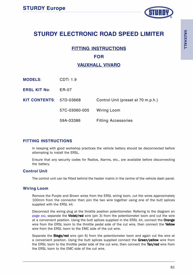
STURDY Europe
81
STURDY ELECTRONIC ROAD SPEED LIMITER
FITTING INSTRUCTIONS
FOR
VAUXHALL VIVARO
MODELS: CDTi 1.9
ERSL KIT No: ER-07
KIT CONTENTS: 57D-03668 Control Unit (preset at 70 m.p.h.)
57C-03060-005 Wiring Loom
59A-03386 Fitting Accessories
FITTING INSTRUCTIONS
In keeping with good workshop practices the vehicle battery should be disconnected beforeattempting to install the ERSL.
Ensure that any security codes for Radios, Alarms, etc., are available before disconnectingthe battery.
Control Unit
The control unit can be fitted behind the heater matrix in the centre of the vehicle dash panel.
Wiring Loom
Remove the Purple and Brown wires from the ERSL wiring loom, cut the wires approximately100mm from the connector then join the two wire together using one of the butt splicessupplied with the ERSL kit.
Disconnect the wiring plug at the throttle position potentiometer. Refering to the diagram onpage xxv, separate the VioleVioleVioleVioleViolet/redt/redt/redt/redt/red wire (pin 3) from the potentiometer loom and cut the wireat a convenient position. Using the butt splices supplied in the ERSL kit, connect the OrangeOrangeOrangeOrangeOrangewire from the ERSL loom to the throttle pedal side of the cut wire, then connect the YYYYYelloelloelloelloellowwwwwwire from the ERSL loom to the EMC side of the cut wire.
Separate the Biege/redBiege/redBiege/redBiege/redBiege/red wire (pin 6) from the potentiometer loom and again cut the wire ata convenient position. Using the butt splices supplied connect the Green/yellowGreen/yellowGreen/yellowGreen/yellowGreen/yellow wire fromthe ERSL loom to the throttle pedal side of the cut wire, then connect the TTTTTan/redan/redan/redan/redan/red wire fromthe ERSL loom to the EMC side of the cut wire.
VV VVVAA AAAUXH
ALLU
XHALL
UXH
ALLU
XHALL
UXH
ALL

STURDY Europe
82
Wiring Loom cont’d
Connect the PinkPinkPinkPinkPink wire from the ERSL loom, in series, to the White/orangeWhite/orangeWhite/orangeWhite/orangeWhite/orange wire (pin 2) inthe potentiometer loom. Connect the Black/yellowBlack/yellowBlack/yellowBlack/yellowBlack/yellow wire from the ERSL loom, in series, withthe Orange/redOrange/redOrange/redOrange/redOrange/red wire (pin 1) in the potentiometer loom.
Once the connections have been made wrap the looms with insulating tape to provide a neatfinish and reconnect the loom to the throttle potentiometer.
To complete the wiring for the ERSL there are a further three connections to be made, thesebeing the Red, Black and Green wires from the ERSL wiring loom.
To obtain a road speed signal, the GreenGreenGreenGreenGreen wire from the ERSL loom should be butt spliced tothe PurplePurplePurplePurplePurple wire (pin 14) from the green connector plug at the rear of the instrument panel.The RedRedRedRedRed wire from the ERSL loom should be routed to the Brake Pedal Switch and spliced tothe Ignition Positive wire to the switch. The BlackBlackBlackBlackBlack wire should have a ring terminal fitted to itand anchored to a chassis ground.
Calibration details
The Sturdy ERSL is supplied with a generic set of calibration characteristics. For the limiter tooperate correctly the characteristics listed below should be programmed into the ERSL ControlUnit.
TABLE PROGRAM CODE LEVEL
1 Speed setting Legal/customer requirement
2 Pole setting (x 1000imp) 26 14
3 Error gain 7 8
4 Response gain 160 11
5 % of WOT 8 52%
6 Not used
7 Not used
8 Speed hold 0 Disabled
9 Not used 0
10 Eng.Sp Error gain 9 10
11 Eng.Sp Response gain 112 8
12 Eng.Sp % of WOT 8 36%
13 (L) Min. voltage 136 9%
13 (H) Max voltage (8+128) 93%
14 Not used
15 Not used
VVVV V AAAA AU
XHAL
LU
XHAL
LU
XHAL
LU
XHAL
LU
XHAL
L

STURDY Europe
83
Re-calibration / changing the set speed
The Sturdy ERSL is supplied with the operating speed set at 70 m.p.h., however the speedsetting can be easily changed to suit the legal or customers specific requirements using theSturdy ER-01 programmer.
Refer to the ER-01 Programming manual for programming details.
Road Test
Although the ERSL is supplied fully calibrated it is essential that, after installation, the vehiclebe road tested to allow the Control Unit to “learn” the calibration settings under road goingconditions. The vehicle should be driven with maximum throttle until the set speed is attained.The maximum throttle position should be maintained for a further 10-20 seconds whilst thecontrol unit learns the calibration settings, a reasonably flat road, clear of traffic, is requiredto carry out this operation efefefefefffffficiently iciently iciently iciently iciently and saf saf saf saf safelyelyelyelyely.....
VV VVVAA AAAUXH
ALLU
XHALL
UXH
ALLU
XHALL
UXH
ALL

STURDY Europe
84
VVVV V AAAA AU
XHAL
LU
XHAL
LU
XHAL
LU
XHAL
LU
XHAL
L
STURDY Europe
85
STURDY ELECTRONIC ROAD SPEED LIMITER
FITTING INSTRUCTIONS
FOR
VOLKSWAGEN LT
MODELS: LT35, LT46
ERSL KIT No: ER-02
KIT CONTENTS:
57D-02996 Control Unit (preset at 70 m.p.h.)
57C-03060-002 Wiring Loom
59A-03115 Fitting Accessories
FITTING INSTRUCTIONS
In keeping with good workshop practices the vehicle battery should be disconnected beforeattempting to install the ERSL.
Ensure that any security codes for Radios, Alarms, etc., are available before disconnectingthe battery.
Control Unit
To allow easy access when siting the ERSL Control Unit it is recommended that the near sideheadlamp assembly be removed.
Using the Control Unit base plate as a template mark the positions of the four fixing holesonto the flat panel between the nearside wheel arch and the front panel of the vehicle directlybelow the headlamp.
Drill 4 x M6 clearance holes, and install the Control Unit using M6 bolts, spacing bushes, nutsand washers (see diagram on page 88). The spacers are used to keep the control unit aboveany water that may collect on the panel where it is fitted.
The Control Unit should be mounted with the electrical connection socket facing the nearside wing of the vehicle.
Wiring Loom
Before connecting the wring loom to the ERSL Control Unit the loom must be modified.
Remove the Green wire from its sheath and install it into the sheath housing the Red andBlack wires.
If control of Engine revs is NOT required then cut the blue wire in such a position that it nolonger protrudes from it’s protective sheath (always tape the cut end).
VOLK
SW
AGEN
VOLK
SW
AGEN
VOLK
SW
AGEN
VOLK
SW
AGEN
VOLK
SW
AGEN

STURDY Europe
86
Wiring Loom cont’d
Remove the Purple and Brown wires from their sheath and cut the wires approximately 200mmfrom the connector, then using a butt splice supplied with the kit join the cut ends of the wirestogether. Feed the joined wires back into the protective sheath.
Connect the ERSL wiring loom to the 18 pin connector in the Control Unit.
Run both sections of the ERSL loom along the main wiring loom for the vehicles ElectronicControl Module (ECM) until it reaches the point where the ECM loom splits. One part of theECM loom runs toward the throttle position potentiometer, the other part being routed throughthe engine bulkhead into the cab of the vehicle following the main wiring bundle.
Select the half of the ERSL loom containing three wires (Red, Black and Green) and run thisthrough the bulkhead access port into the cab of the vehicle (a wire threader will be requiredfor this operation).
The other half of the ERSL wiring loom should follow the routing of the Throttle positionpotentiometer wiring.
At the Throttle potentiometer, disconnect the vehicle wiring from the potentiometer and usingan appropriate tool remove approximately 150 mm of canvas wrap from the wiring loom.
Referring to the schematic diagram on page xxii, separate the WhiteWhiteWhiteWhiteWhite wire (pin 5) from thepotentiometer loom and cut the wire at a convenient position.
Using the butt splices supplied in the ERSL kit, connect the OrangeOrangeOrangeOrangeOrange wire from the ERSL loomto the throttle pedal side of the cut wire. Then connect the YYYYYelloelloelloelloellowwwww wire from the ERSL loomto the ECM side of the cut wire.
Connect the PinkPinkPinkPinkPink wire from the ERSL loom in series with the YYYYYelloelloelloelloellowwwww wire (pin 6) in thepotentiometer loom.
Once the connections have been made wrap the looms with insulating tape to provide a neatfinish and reconnect the loom to the throttle potentiometer.
Secure the ERSL loom to the vehicle wiring using cable ties.
The other half of the ERSL loom (Red, Black and Green wires) should now be routed behindthe dashboard (over the transmission tunnel and the steering column support struts), to thewiring bundle situated behind the lower dashboard panel to the right of the steering column(see diagram on page 89).
Crimp the ring terminal supplied to the Black (negative) lead in the ERSL loom and connect tothe cab earth point in the driver’s foot well.
Locate the speedometer signal generator lead and disconnect the two-pin plug.
Using a suitable tool remove approximately 200mm of the cable outer covering, splice theGreen wire from the ERSL loom together with the signal wire (white) from the generator usingthe butt splice supplied and refit the two halves of the plug (see page 89).
Locate and separate from its wiring bundle the positive wire (white/red trace) to the brakelights, splice the red (positive) lead from the ERSL loom to this wire using the butt splicesupplied.
VOLK
SW
AGEN
VOLK
SW
AGEN
VOLK
SW
AGEN
VOLK
SW
AGEN
VOLK
SW
AGEN

STURDY Europe
87
Calibration details
The Sturdy ERSL is supplied with a generic set of calibration characteristics. For the limiter tooperate correctly the characteristics listed below should be programmed into the ERSL ControlUnit.
TABLE PROGRAM CODE LEVEL
1 Speed setting Legal/customer requirement
2 Pole setting (x 1000imp) 24 13
3 Error gain 6 7
4 Response gain 144 10
5 % of WOT 8 52%
6 Not used
7 Not used
8 Engine rev setting
9 Eng.Sp Alternator poles 17
10 Eng.Sp Error gain 9
11 Eng.Sp Response gain 1
12 Eng.Sp % of WOT 36%
13 (L) Min. voltage 136 9%
13 (H) Max voltage (8+128) 93%
14 Not used
15 Not used
When fitted to LT46 it will be necessary to program the speed setting to 1 m.p.h. above therequired set speed. See ER-01 Programming Manual for details.
Re-calibration / changing the set speed
The Sturdy ERSL is supplied with the operating speed set at 70 m.p.h., however the speedsetting can be easily changed to suit the customers specific requirements using the SturdyER-01 programmer.
Refer to the ER-01 Programming manual for calibrating details.
Road Test
Although the ERSL is supplied fully calibrated it is essential that, after installation, the vehiclebe road tested to allow the Control Unit to “learn” the calibration settings under road goingconditions. The vehicle should be driven with maximum throttle until the set speed is attained.The maximum throttle position should be maintained for a further 10-20 seconds whilst thecontrol unit learns the calibration settings, a reasonably flat road, clear of traffic, is requiredto carry out this operation efefefefefffffficiently and saficiently and saficiently and saficiently and saficiently and safelyelyelyelyely.....
VOLK
SW
AGEN
VOLK
SW
AGEN
VOLK
SW
AGEN
VOLK
SW
AGEN
VOLK
SW
AGEN

STURDY Europe
88
ERSL Control Module
LT series Engine Bay
FIG 1. ERSL Control Module position
VOLK
SW
AGEN
VOLK
SW
AGEN
VOLK
SW
AGEN
VOLK
SW
AGEN
VOLK
SW
AGEN

STURDY Europe
89
Speed Generator Lead
Speed Generator Lead
B+ Ignition Pos
Green wire from ERSL loom
VOLK
SW
AGEN
VOLK
SW
AGEN
VOLK
SW
AGEN
VOLK
SW
AGEN
VOLK
SW
AGEN

STURDY Europe
90
VOLK
SW
AGEN
VOLK
SW
AGEN
VOLK
SW
AGEN
VOLK
SW
AGEN
VOLK
SW
AGEN

STURDY Europe
91
STURDY ELECTRONIC ROAD SPEED LIMITER
FITTING INSTRUCTIONS
FOR
VOLKSWAGEN TRANSPORTER TDI
MODELS: T4
ERSL KIT No: ER-02
KIT CONTENTS: 57D-02996 Control Unit (preset at 70 m.p.h.)
57C-03060-002 Wiring Loom
59A-03115 Fitting Accessories
FITTING INSTRUCTIONS
In keeping with good workshop practices the vehicle battery should be disconnected beforeattempting to install the ERSL.
Ensure that any security codes for Radios, Alarms, etc., are available before disconnectingthe battery.
Control Unit
Find a suitable position within the cab of the vehicle and secure the Control Unit, ensuringthat the site is not directly in the air flow from any heater ducts.
Wiring Loom
Remove the Purple and Brown wires from their sheath and cut the wires approximately 200mmfrom the connector, then using a butt splice supplied with the kit join the cut ends of the wirestogether. Feed the joined wires back into the protective sheath.
Connect the ERSL wiring loom to the 18pin connector in the Control Unit.
Select the ERSL loom containing three wires (Red, Black and Green) and run this to the fusepanel / main connector bank (lower right hand side of dash). At this point connect the BlackBlackBlackBlackBlackwire in the ERSL loom to a vehicle negative, the RedRedRedRedRed wire in the ERSL loom to an ignitionswitched positive (Black/yellowBlack/yellowBlack/yellowBlack/yellowBlack/yellow) and the GreenGreenGreenGreenGreen wire to the White/blueWhite/blueWhite/blueWhite/blueWhite/blue wire from the halleffect sender on the gearbox (G22).
Route the other half of the ERSL wiring loom to the vehicle wiring harness that runs to thethrottle potentiometer.
VOLK
SW
AGEN
VOLK
SW
AGEN
VOLK
SW
AGEN
VOLK
SW
AGEN
VOLK
SW
AGEN
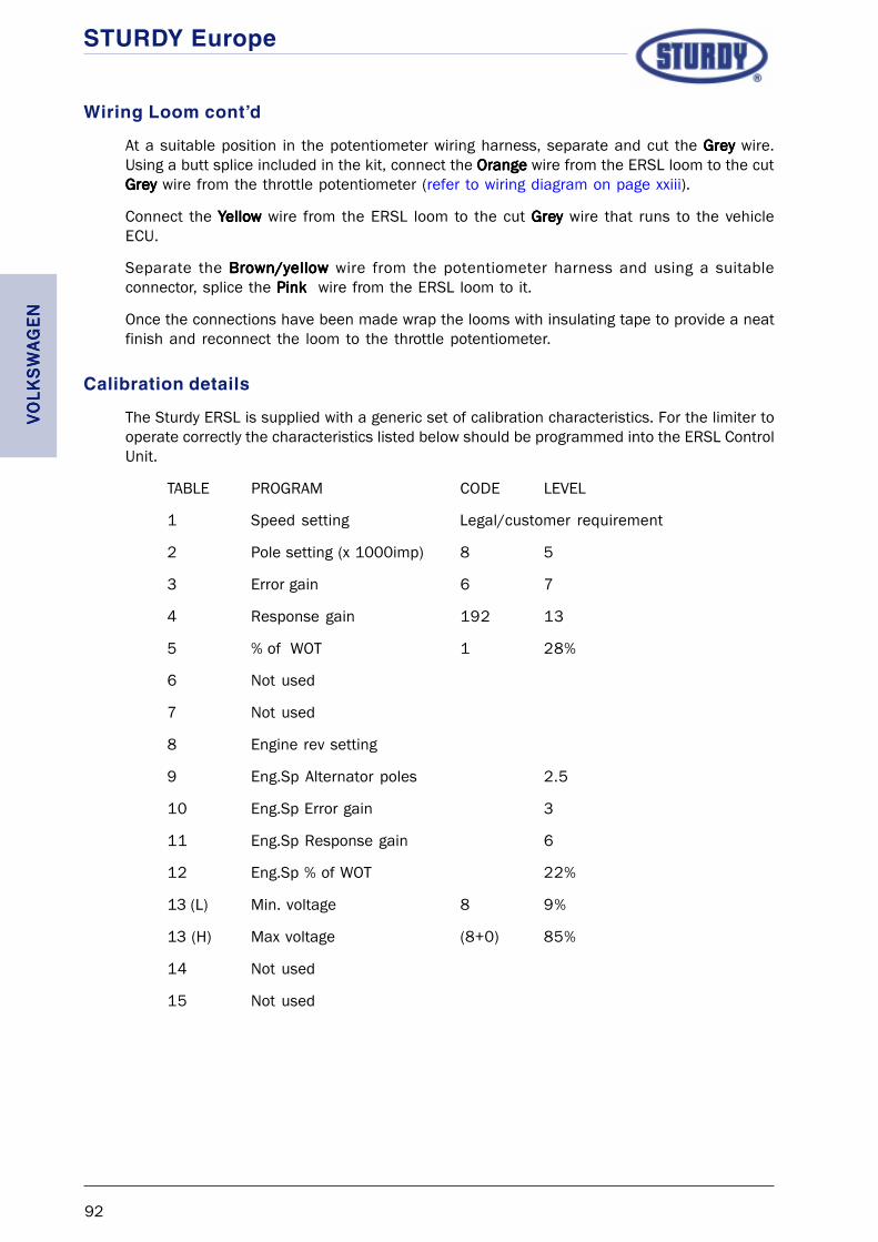
STURDY Europe
92
Wiring Loom cont’d
At a suitable position in the potentiometer wiring harness, separate and cut the GreyGreyGreyGreyGrey wire.Using a butt splice included in the kit, connect the OrangeOrangeOrangeOrangeOrange wire from the ERSL loom to the cutGreyGreyGreyGreyGrey wire from the throttle potentiometer (refer to wiring diagram on page xxiii).
Connect the YYYYYelloelloelloelloellowwwww wire from the ERSL loom to the cut GreGreGreGreGreyyyyy wire that runs to the vehicleECU.
Separate the Brown/yellowBrown/yellowBrown/yellowBrown/yellowBrown/yellow wire from the potentiometer harness and using a suitableconnector, splice the PinkPinkPinkPinkPink wire from the ERSL loom to it.
Once the connections have been made wrap the looms with insulating tape to provide a neatfinish and reconnect the loom to the throttle potentiometer.
Calibration details
The Sturdy ERSL is supplied with a generic set of calibration characteristics. For the limiter tooperate correctly the characteristics listed below should be programmed into the ERSL ControlUnit.
TABLE PROGRAM CODE LEVEL
1 Speed setting Legal/customer requirement
2 Pole setting (x 1000imp) 8 5
3 Error gain 6 7
4 Response gain 192 13
5 % of WOT 1 28%
6 Not used
7 Not used
8 Engine rev setting
9 Eng.Sp Alternator poles 2.5
10 Eng.Sp Error gain 3
11 Eng.Sp Response gain 6
12 Eng.Sp % of WOT 22%
13 (L) Min. voltage 8 9%
13 (H) Max voltage (8+0) 85%
14 Not used
15 Not used
VOLK
SW
AGEN
VOLK
SW
AGEN
VOLK
SW
AGEN
VOLK
SW
AGEN
VOLK
SW
AGEN

STURDY Europe
93
Re-calibration / changing the set speed
The Sturdy ERSL is supplied with the operating speed set at 70 m.p.h., however the speedsetting can be easily changed to suit the customers specific requirements using the SturdyER-01 programmer.
Refer to the ER-01 Programming manual for calibrating details.
Road Test
Although the ERSL is supplied fully calibrated it is essential that, after installation, the vehiclebe road tested to allow the Control Unit to “learn” the calibration settings under road goingconditions. The vehicle should be driven with maximum throttle until the set speed is attained.The maximum throttle position should be maintained for a further 10-20 seconds whilst thecontrol unit learns the calibration settings, a reasonably flat road, clear of traffic, is requiredto carry out this operation efefefefefffffficiently iciently iciently iciently iciently and saf saf saf saf safelyelyelyelyely.....
VOLK
SW
AGEN
VOLK
SW
AGEN
VOLK
SW
AGEN
VOLK
SW
AGEN
VOLK
SW
AGEN

STURDY Europe
94
VOLK
SW
AGEN
VOLK
SW
AGEN
VOLK
SW
AGEN
VOLK
SW
AGEN
VOLK
SW
AGEN

STURDY Europe
95
STURDY ELECTRONIC ROAD SPEED LIMITER
FITTING INSTRUCTIONS
FOR
VOLKSWAGEN TRANSPORTER TDI
MODELS: T5 (all engine varients)
ERSL KIT No: ER-02
KIT CONTENTS: 57D-02996 Control Unit (preset at 70 m.p.h.)
57C-03060-002 Wiring Loom
59A-03115 Fitting Accessories
FITTING INSTRUCTIONS
Ensure that any security codes for Radios, Alarms, etc., are available before disconnectingthe battery.
Remove the battery cover, disconnect and remove the battery and battery tray, then removethe E-box cover (see Figures 1, 2 and 3).
Figure 1. Figure 2.
Figure 3.
VOLK
SW
AGEN
VOLK
SW
AGEN
VOLK
SW
AGEN
VOLK
SW
AGEN
VOLK
SW
AGEN

STURDY Europe
96
Control Unit
Using double-sided tape fix the Control Unit to thetop of the vehicle ECM Unit (see Figure 4).
Wiring Loom
At the ERSL wiring loom, remove the Purple and Brown wires from their sheath and cut thewires approximately 200mm from the connector, then using a butt splice supplied with the kitjoin the cut ends of the wires together. Feed the joined wires back into the protective sheath.
Connect the ERSL wiring loom to the 18pin connector in the Control Unit.
Connect the BlackBlackBlackBlackBlack lead from the ERSL loom to theupper earthing point to the right of the E-box (seeFigure 5).
Disconnect the Blue plug (T10d) from the E-boxcoupling station (see Figure 6).
Refering to the wiring diagram on page xxiv, splicethe PinkPinkPinkPinkPink wire from the ERSL loom to the Grey/redGrey/redGrey/redGrey/redGrey/red(T10d/4) wire in the 10 pin connector plug.
Approximately 50mm from the Blue plug cut theWhite/blueWhite/blueWhite/blueWhite/blueWhite/blue (T10d/5) wire. Using a supplied buttsplice, connect the OrangeOrangeOrangeOrangeOrange wire from the ERSL loomto the Blue connector side of the cut wire.
Again using a butt splice as supplied, connect theYYYYYelloelloelloelloellowwwww wire from the ERSL loom to the engine controlside of the cut wire.
Figure 4.
Figure 5.
Figure 6.
VOLK
SW
AGEN
VOLK
SW
AGEN
VOLK
SW
AGEN
VOLK
SW
AGEN
VOLK
SW
AGEN
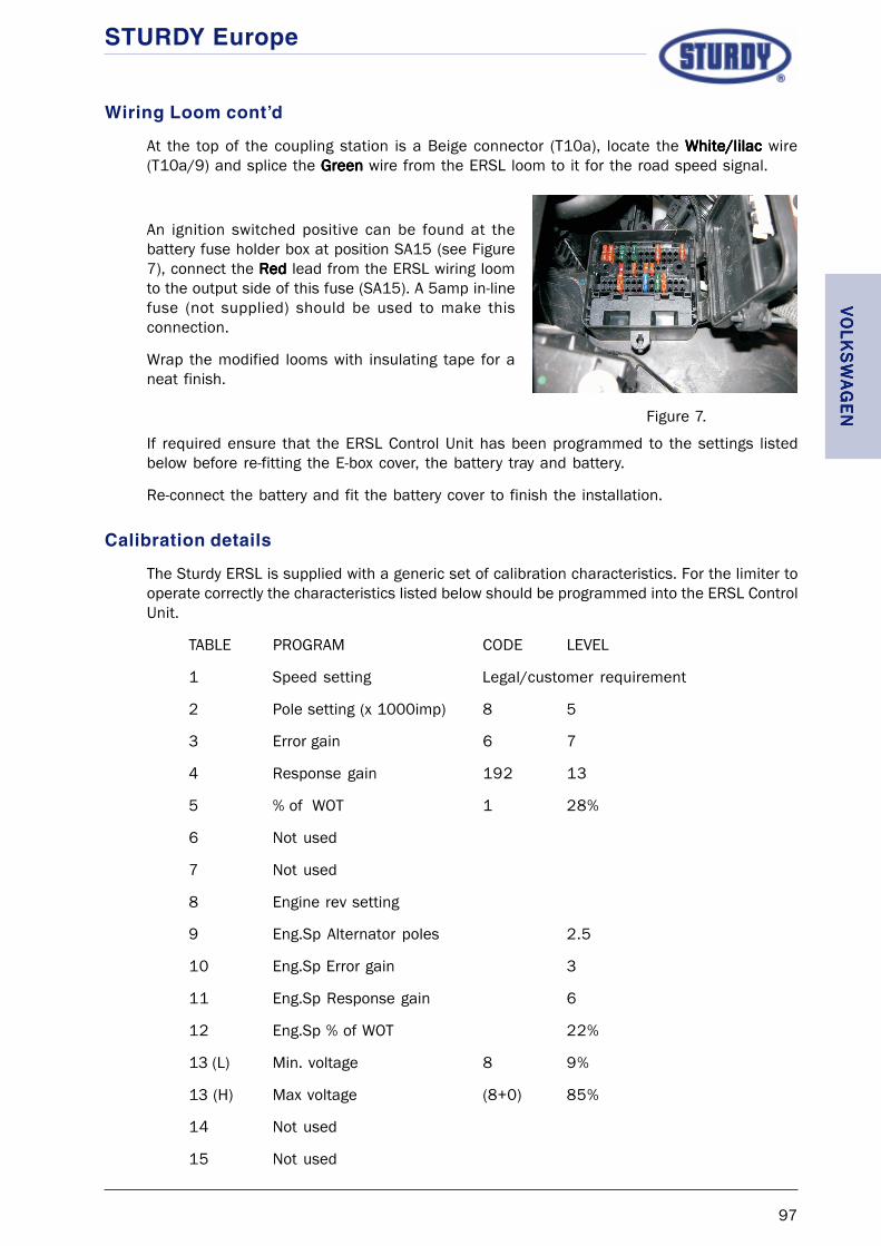
STURDY Europe
97
Wiring Loom cont’d
At the top of the coupling station is a Beige connector (T10a), locate the White/lilacWhite/lilacWhite/lilacWhite/lilacWhite/lilac wire(T10a/9) and splice the GreenGreenGreenGreenGreen wire from the ERSL loom to it for the road speed signal.
An ignition switched positive can be found at thebattery fuse holder box at position SA15 (see Figure7), connect the RedRedRedRedRed lead from the ERSL wiring loomto the output side of this fuse (SA15). A 5amp in-linefuse (not supplied) should be used to make thisconnection.
Wrap the modified looms with insulating tape for aneat finish.
If required ensure that the ERSL Control Unit has been programmed to the settings listedbelow before re-fitting the E-box cover, the battery tray and battery.
Re-connect the battery and fit the battery cover to finish the installation.
Calibration details
The Sturdy ERSL is supplied with a generic set of calibration characteristics. For the limiter tooperate correctly the characteristics listed below should be programmed into the ERSL ControlUnit.
TABLE PROGRAM CODE LEVEL
1 Speed setting Legal/customer requirement
2 Pole setting (x 1000imp) 8 5
3 Error gain 6 7
4 Response gain 192 13
5 % of WOT 1 28%
6 Not used
7 Not used
8 Engine rev setting
9 Eng.Sp Alternator poles 2.5
10 Eng.Sp Error gain 3
11 Eng.Sp Response gain 6
12 Eng.Sp % of WOT 22%
13 (L) Min. voltage 8 9%
13 (H) Max voltage (8+0) 85%
14 Not used
15 Not used
Figure 7.
VOLK
SW
AGEN
VOLK
SW
AGEN
VOLK
SW
AGEN
VOLK
SW
AGEN
VOLK
SW
AGEN

STURDY Europe
98
Re-calibration / changing the set speed
The Sturdy ERSL is supplied with the operating speed set at 70 m.p.h., however the speedsetting can be easily changed to suit the customers specific requirements using the SturdyER-01 programmer.
Refer to the ER-01 Programming manual for calibrating details.
Road Test
Although the ERSL is supplied fully calibrated it is essential that, after installation, the vehiclebe road tested to allow the Control Unit to “learn” the calibration settings under road goingconditions. The vehicle should be driven with maximum throttle until the set speed is attained.The maximum throttle position should be maintained for a further 10-20 seconds whilst thecontrol unit learns the calibration settings, a reasonably flat road, clear of traffic, is requiredto carry out this operation efefefefefffffficiently iciently iciently iciently iciently and saf saf saf saf safelyelyelyelyely.....
VOLK
SW
AGEN
VOLK
SW
AGEN
VOLK
SW
AGEN
VOLK
SW
AGEN
VOLK
SW
AGEN

STURDY Europe
99

STURDY Europe
100
STURDY Europe
i
Throttle Pedal
Wiring Diagrams
Important Note:Whilst all efforts are made to ensure that the informaton on the following pages are correct,
Sturdy Europe will not be held responsible for any errors that may occur due to technicalchanges made by vehicle manufacturers.

STURDY Europe
ii

STURDY Europe
iii
Aptec Williams Throttle ControlWiring Detail
E C M
Road Speed Signal 12 volt from Ignition Sw (B+)
GroundEngine Speed Signal (revs)
White
Black
Throttle PositionSensor
18 Pin ERSL module connector
10
Re
d
Bla
ck
Pu
rple
Bro
wn
Pin
k
Ora
ng
e
Ye
llow
Gre
en
Blu
e
11 1291 16 17 8 7
Red
0 v
0.56 v to 3.88 v
4.94 v
Return to fittingReturn to fittingReturn to fittingReturn to fittingReturn to fittinginstructionsinstructionsinstructionsinstructionsinstructions

STURDY Europe
iv
Citr en RelayWiring Detail
ö
E C M
Road Speed Signal
Engine Speed Signal (revs)
Brown/white
Blue/black
Throttle PositionSensor
18 Pin ERSL module connector
10
Ground
Bla
ck
12 volt from Ignition Sw (B+)
Red
Gre
en/y
ello
w
Tan/r
ed
Pin
k
Ora
nge
Yello
w
Gre
en
Blu
e
11 1291 16 17 8 7
Bro
wn
Purp
le
1514
Bla
ck/y
ello
w
18
Purple/black
Brown/black
Return to fittingReturn to fittingReturn to fittingReturn to fittingReturn to fittinginstructionsinstructionsinstructionsinstructionsinstructions

STURDY Europe
v
1
2
356
4
DAF LF SeriesWiring Detail
E C M
Road Speed Signal 12 volt from Ignition Sw (B+)
GroundEngine Speed Signal (revs)
Grey 4680
Grey 4679
Throttle PositionSensor
18 Pin ERSL module connector
10
Red
Bla
ck
Purp
le
Bro
wn
Pin
k
Ora
nge
Yello
w
Gre
en
Blu
e
11 1291 16 17 8 7
Return to fittingReturn to fittingReturn to fittingReturn to fittingReturn to fittinginstructionsinstructionsinstructionsinstructionsinstructions

STURDY Europe
vi
17
245
6
E C M
Road Speed Signal
Engine Speed Signal (revs)
Brown/red
White
Throttle PositionSensor
18 Pin ERSL module connector
10
Ground
Bla
ck
12 volt from Ignition Sw (B+)
Red
Gre
en/y
ello
w
Tan/r
ed
Pin
k
Ora
nge
Yello
w
Gre
en
Blu
e
11 1291 16 17 8 7
Bro
wn
Purp
le
1514
Bla
ck/y
ello
w
18
White/red
White/blue
Brown/blue
Ford Focus 1.8DWiring Detail
Return to fittingReturn to fittingReturn to fittingReturn to fittingReturn to fittinginstructionsinstructionsinstructionsinstructionsinstructions

STURDY Europe
vii
1
2
345
6
Ford RangerWiring Detail
E C M
Road Speed Signal
Engine Speed Signal (revs)
Pink
Red
Throttle PositionSensor
18 Pin ERSL module connector
10
Ground
Bla
ck
12 volt from Ignition Sw (B+)
Re
d
Gre
en
/ye
llow
Ta
n/r
ed
Pin
k
Ora
ng
e
Ye
llow
Gre
en
Blu
e
11 1291 16 17 8 7
Bro
wn
Pu
rple
1514
Bla
ck/y
ello
w
18
Brown/black
Return to fittingReturn to fittingReturn to fittingReturn to fittingReturn to fittinginstructionsinstructionsinstructionsinstructionsinstructions

STURDY Europe
viii
321
4
Ford Transit up to Nov 1997Wiring Detail
E C M
Road Speed Signal 12 volt from Ignition Sw (B+)
GroundEngine Speed Signal (revs)
Throttle PositionSensor
18 Pin ERSL module connector
10
Red
Bla
ck
Purp
le
Bro
wn
Pin
k
Ora
nge
Yello
w
Gre
en
Blu
e
11 1291 16 17 8 7
Return to fittingReturn to fittingReturn to fittingReturn to fittingReturn to fittinginstructionsinstructionsinstructionsinstructionsinstructions

STURDY Europe
ix
51
7
Ford Transit after Nov’97Wiring Detail
E C M
Road Speed Signal 12 volt from Ignition Sw (B+)
GroundEngine Speed Signal (revs)
Brown
White
Throttle PositionSensor
18 Pin ERSL module connector
10
Red
Bla
ck
Pu
rple
Bro
wn
Pin
k
Ora
ng
e
Ye
llow
Gre
en
Blu
e
11 1291 16 17 8 7
Grey
Return to fittingReturn to fittingReturn to fittingReturn to fittingReturn to fittinginstructionsinstructionsinstructionsinstructionsinstructions

STURDY Europe
x
1
5
647
2
Ford Transit 2000Wiring Detail
E C M
Road Speed Signal
Engine Speed Signal (revs)
Grey/violet
Blue/white
Throttle PositionSensor
18 Pin ERSL module connector
10
Ground
Bla
ck
12 volt from Ignition Sw (B+)
Red
Gre
en/y
ello
w
Tan/r
ed
Pin
k
Ora
nge
Yello
w
Gre
en
Blu
e
11 1291 16 17 8 7
Bro
wn
Purp
le
1514
Bla
ck/y
ello
w
18
Grey/orange
Grey/black
Grey/red
Return to fittingReturn to fittingReturn to fittingReturn to fittingReturn to fittinginstructionsinstructionsinstructionsinstructionsinstructions

STURDY Europe
xi
1
5
647
2
Ford Transit 2005Wiring Detail
E C M
Road Speed Signal
Engine Speed Signal (revs)
Brown/blue
White/blue
Throttle PositionSensor
18 Pin ERSL module connector
10
Ground
Bla
ck
12 volt from Ignition Sw (B+)
Red
Gre
en/y
ello
w
Tan/r
ed
Pin
k
Ora
nge
Yello
w
Gre
en
Blu
e
11 1291 16 17 8 7
Bro
wn
Purp
le
1514
Bla
ck/y
ello
w
18
White
White/red
Brown/red
Return to fittingReturn to fittingReturn to fittingReturn to fittingReturn to fittinginstructionsinstructionsinstructionsinstructionsinstructions
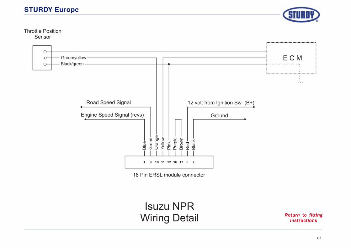
STURDY Europe
xii
Isuzu NPRWiring Detail
E C M
Road Speed Signal 12 volt from Ignition Sw (B+)
GroundEngine Speed Signal (revs)
Black/green
Green/yellow
Throttle PositionSensor
18 Pin ERSL module connector
10
Red
Bla
ck
Purp
le
Bro
wn
Pin
k
Ora
nge
Yello
w
Gre
en
Blu
e
11 1291 16 17 8 7
Return to fittingReturn to fittingReturn to fittingReturn to fittingReturn to fittinginstructionsinstructionsinstructionsinstructionsinstructions

STURDY Europe
xiii
1
2
345
6
Isuzu NQRWiring Detail
E C M
Road Speed Signal 12 volt from Ignition Sw (B+)
GroundEngine Speed Signal (revs)
Blue
Blue/white
Throttle PositionSensor
18 Pin ERSL module connector
10
Red
Bla
ck
Purp
le
Bro
wn
Pin
k
Ora
nge
Yello
w
Gre
en
Blu
e
11 1291 16 17 8 7
Red
White
Black
Blue/red
Return to fittingReturn to fittingReturn to fittingReturn to fittingReturn to fittinginstructionsinstructionsinstructionsinstructionsinstructions

STURDY Europe
xiv
1
2
345
6
Iveco Daily EDC .13Wiring Detail
E C M
Road Speed Signal 12 volt from Ignition Sw (B+)
GroundEngine Speed Signal (revs)
Brown (0150)
Orange (5157)
Throttle PositionSensor
18 Pin ERSL module connector
10
Red
Bla
ck
Purp
le
Bro
wn
Pin
k
Ora
nge
Yello
w
Gre
en
Blu
e
11 1291 16 17 8 7
Return to fittingReturn to fittingReturn to fittingReturn to fittingReturn to fittinginstructionsinstructionsinstructionsinstructionsinstructions

STURDY Europe
xv
1
5
647
2
LDV Convoy 2.4D Turbo (2000)Wiring Detail
E C M
Road Speed Signal
Engine Speed Signal (revs)
Purple/yellow
Grey
Throttle PositionSensor
18 Pin ERSL module connector
10
Ground
Bla
ck
12 volt from Ignition Sw (B+)
Red
Gre
en/y
ello
w
Tan/r
ed
Pin
k
Ora
nge
Yello
w
Gre
en
Blu
e
11 1291 16 17 8 7
Bro
wn
Purp
le
1514
Bla
ck/y
ello
w
18
White/blue
White
Brown
Return to fittingReturn to fittingReturn to fittingReturn to fittingReturn to fittinginstructionsinstructionsinstructionsinstructionsinstructions
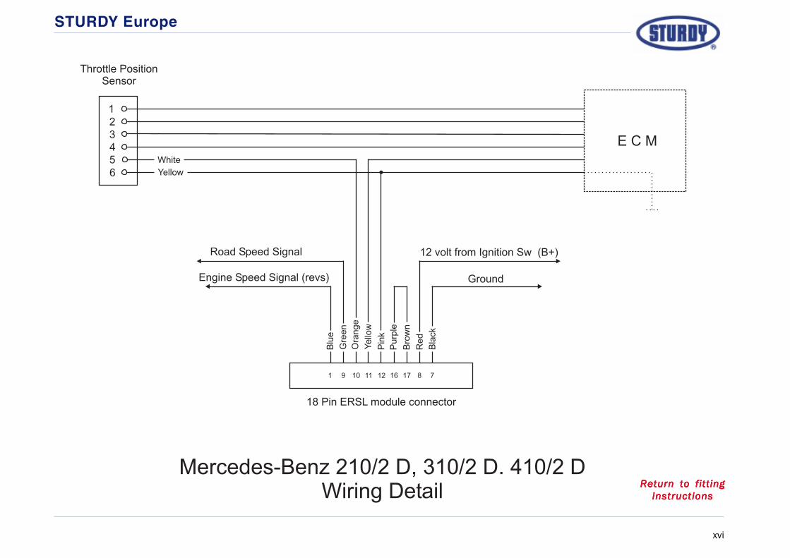
STURDY Europe
xvi
1
2
345
6
Mercedes-Benz 210/2 D, 310/2 D. 410/2 DWiring Detail
E C M
Road Speed Signal 12 volt from Ignition Sw (B+)
GroundEngine Speed Signal (revs)
Yellow
White
Throttle PositionSensor
18 Pin ERSL module connector
10
Red
Bla
ck
Purp
le
Bro
wn
Pin
k
Ora
nge
Yello
w
Gre
en
Blu
e
11 1291 16 17 8 7
Return to fittingReturn to fittingReturn to fittingReturn to fittingReturn to fittinginstructionsinstructionsinstructionsinstructionsinstructions

STURDY Europe
xvii
Mitsubishi CanterWiring Detail
E C M
Road Speed Signal
Engine Speed Signal (revs)
Green/red
Green/blue
Throttle PositionSensor
18 Pin ERSL module connector
10
Ground
Bla
ck
12 volt from Ignition Sw (B+)
Red
Gre
en/y
ello
w
Tan/r
ed
Pin
k
Ora
nge
Yello
w
Gre
en
Blu
e
11 1291 16 17 8 7
Bro
wn
Purp
le
1514
Bla
ck/y
ello
w
18
Blue
Return to fittingReturn to fittingReturn to fittingReturn to fittingReturn to fittinginstructionsinstructionsinstructionsinstructionsinstructions
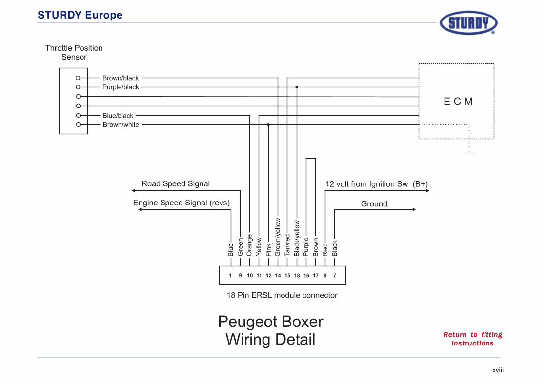
STURDY Europe
xviii
Peugeot BoxerWiring Detail
E C M
Road Speed Signal
Engine Speed Signal (revs)
Brown/white
Blue/black
Throttle PositionSensor
18 Pin ERSL module connector
10
Ground
Bla
ck
12 volt from Ignition Sw (B+)
Red
Gre
en/y
ello
w
Tan/r
ed
Pin
k
Ora
nge
Yello
w
Gre
en
Blu
e
11 1291 16 17 8 7
Bro
wn
Purp
le
1514
Bla
ck/y
ello
w
18
Purple/black
Brown/black
Return to fittingReturn to fittingReturn to fittingReturn to fittingReturn to fittinginstructionsinstructionsinstructionsinstructionsinstructions

STURDY Europe
xix
1
2
345
6
Renault MasterWiring Detail
E C M
Road Speed Signal
Engine Speed Signal (revs)
Yellow
White
Throttle PositionSensor
18 Pin ERSL module connector
10
Ground
Bla
ck
12 volt from Ignition Sw (B+)
Red
Gre
en/y
ello
w
Tan/r
ed
Pin
k
Ora
nge
Yello
w
Gre
en
Blu
e
11 1291 16 17 8 7
Bro
wn
Purp
le
1514
Bla
ck/y
ello
w
18
Brown
Purple
Pink
Orange
Return to fittingReturn to fittingReturn to fittingReturn to fittingReturn to fittinginstructionsinstructionsinstructionsinstructionsinstructions
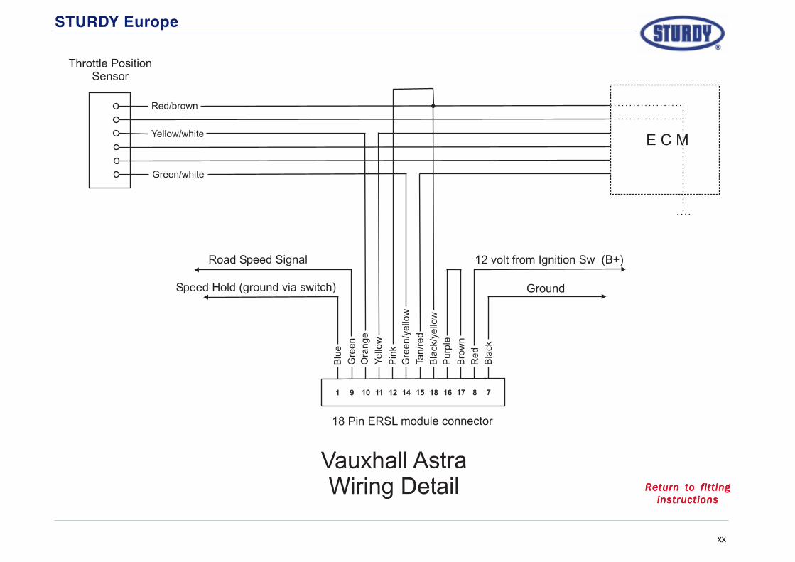
STURDY Europe
xx
Vauxhall AstraWiring Detail
E C M
Road Speed Signal
Speed Hold (ground via switch)
Green/white
Throttle PositionSensor
18 Pin ERSL module connector
10
Ground
Bla
ck
12 volt from Ignition Sw (B+)
Red
Gre
en/y
ello
w
Tan/r
ed
Pin
k
Ora
nge
Yello
w
Gre
en
Blu
e
11 1291 16 17 8 7
Bro
wn
Purp
le
1514
Bla
ck/y
ello
w
18
Yellow/white
Red/brown
Return to fittingReturn to fittingReturn to fittingReturn to fittingReturn to fittinginstructionsinstructionsinstructionsinstructionsinstructions

STURDY Europe
xxi
Vauxhall Combo CDTIWiring Detail
E C M
Road Speed Signal
Speed Hold (ground via switch)
Green/white
Throttle PositionSensor
18 Pin ERSL module connector
10
Ground
Bla
ck
12 volt from Ignition Sw (B+)
Re
d
Gre
en
/ye
llow
Ta
n/r
ed
Pin
k
Ora
ng
e
Ye
llow
Gre
en
Blu
e
11 1291 16 17 8 7
Bro
wn
Pu
rple
1514
Bla
ck/y
ello
w
18
Blue/brown
Yellow/white
Red/brown
Return to fittingReturn to fittingReturn to fittingReturn to fittingReturn to fittinginstructionsinstructionsinstructionsinstructionsinstructions

STURDY Europe
xxii
1
2
345
6
Volkswagen LT35 & LT46Wiring Detail
E C M
Road Speed Signal 12 volt from Ignition Sw (B+)
GroundEngine Speed Signal (revs)
Yellow
White
Throttle PositionSensor
18 Pin ERSL module connector
10
Red
Bla
ck
Purp
le
Bro
wn
Pin
k
Ora
nge
Yello
w
Gre
en
Blu
e
11 1291 16 17 8 7
Return to fittingReturn to fittingReturn to fittingReturn to fittingReturn to fittinginstructionsinstructionsinstructionsinstructionsinstructions

STURDY Europe
xxiii
1
2
345
6
Volkswagen Transporter T4Wiring Detail
E C M
Road Speed Signal 12 volt from Ignition Sw (B+)
GroundEngine Speed Signal (revs)
Brown/yellow
Grey
Throttle PositionSensor
18 Pin ERSL module connector
10
Red
Bla
ck
Purp
le
Bro
wn
Pin
k
Ora
nge
Yello
w
Gre
en
Blu
e
11 1291 16 17 8 7
Return to fittingReturn to fittingReturn to fittingReturn to fittingReturn to fittinginstructionsinstructionsinstructionsinstructionsinstructions
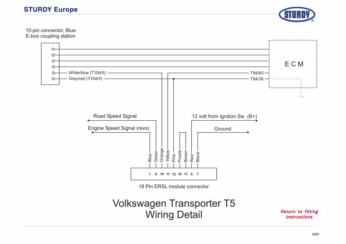
STURDY Europe
xxiv
Volkswagen Transporter T5Wiring Detail
E C M
Road Speed Signal 12 volt from Ignition Sw (B+)
GroundEngine Speed Signal (revs)
White/blue (T10d/5)
Grey/red (T10d/4)
10-pin connector, BlueE-box coupling station
18 Pin ERSL module connector
10
Red
Bla
ck
Purp
le
Bro
wn
Pin
k
Ora
nge
Yello
w
Gre
en
Blu
e
11 1291 16 17 8 7
T94/39
T94/83
Return to fittingReturn to fittingReturn to fittingReturn to fittingReturn to fittinginstructionsinstructionsinstructionsinstructionsinstructions

STURDY Europe
xxv
Vauxhall VivaroWiring Detail
E C M
Road Speed Signal
Speed Hold (ground via switch)
Biege/red
Throttle PositionSensor
18 Pin ERSL module connector
10
Ground
Bla
ck
12 volt from Ignition Sw (B+)
Re
d
Gre
en
/ye
llow
Ta
n/r
ed
Pin
k
Ora
ng
e
Ye
llow
Gre
en
Blu
e
11 1291 16 17 8 7
Bro
wn
Pu
rple
1514
Bla
ck/y
ello
w
18
Violet/red
Orange/red1
2
3
4
5
6
White/orange
Return to fittingReturn to fittingReturn to fittingReturn to fittingReturn to fittinginstructionsinstructionsinstructionsinstructionsinstructions

STURDY Europe
xxvi

STURDY Europe
xxvii

STURDY Europe
xxviii


