Electronic Systems - A1 27/04/2009 2008 DDC - 2006 Storey 1 27/04/2009 - 1 ElnSysA1 - 2008 DDC ELECTRONIC SYSTEMS A – INTRODUCTION A.1 – Organization and contents » Goals and organization » Systems and modules » Analog and digital signals » Benefits of digital electronics Politecnico di Torino - ICT school 27/04/2009 - 2 ElnSysA1 - 2008 DDC INDUSTRIAL ENGINEERING DIGITAL ELECTRONICS MATH, INFORMATICS, PHYSICS, CIRCUITS, .. Basic concepts, functions, signals, …. Courses in Electronics (ideal) ELECTRONIC SYSTEMS ELECTRONIC DEVICES ANALOG ELECTRONICS 27/04/2009 - 3 ElnSysA1 - 2008 DDC INDUSTRIAL ENGINEERING DIGITAL ELECTRONICS MATH, INFORMATICS, PHYSICS, CIRCUITS, .. Courses in Electronics (actual) ELECTRONIC SYSTEMS ELECTRONIC DEVICES ANALOG ELECTRONICS DIGITAL ELECTRONICS ELECTRONIC DEVICES NOW 27/04/2009 - 4 ElnSysA1 - 2008 DDC Goals of the “Electronics” courses • Electronic systems – Basic concepts and techniques. » Systems as a set of functional units, defined by external parameters (models), » Use of feedback » Analog and digital signals and circuits: benefits and drawbacks » Interfaces and power handling » Examples of applications • Unique course in electronics for industrial engineers – What can be done with electronics • First of a sequence for ICT engineers – Applications and design in the following
Transcript
Electronic Systems - A1 27/04/2009
2008 DDC - 2006 Storey 1
27/04/2009 - 1 ElnSysA1 - 2008 DDC
ELECTRONIC SYSTEMS
A – INTRODUCTIONA.1 – Organization and contents
» Goals and organization» Systems and modules» Analog and digital signals» Benefits of digital electronics
• Electronic systems– Basic concepts and techniques.
» Systems as a set of functional units, defined by external parameters (models),
» Use of feedback» Analog and digital signals and circuits: benefits and drawbacks» Interfaces and power handling» Examples of applications
• Unique course in electronics for industrial engineers– What can be done with electronics
• First of a sequence for ICT engineers– Applications and design in the following
Electronic Systems - A1 27/04/2009
2008 DDC - 2006 Storey 2
27/04/2009 - 5 ElnSysA1 - 2008 DDC
Course content
• Electronic systems• Sensors and actuators• Bode plots• Amplification• Control and feedback• Operational amplifiers• Semiconductors and diodes• Field-effect and bipolar transistors• Power electronics
27/04/2009 - 6 ElnSysA1 - 2008 DDC
What you should already know
• Circuit theory– RLC networks with controlled sources, Laplace transform (s)
• Mathematics– Linear equation systems, Differential equations (order I)
• Informatics – Boolean algebra, logic operators
• Physics – Basic mechanics, electric and magnetic fields
• Signal theory– Frequency domain analysis (qualitative)
27/04/2009 - 7 ElnSysA1 - 2008 DDC
Content of this lesson (A1)
• Course goals• Course organization• Exams • Prerequisites• Why “Electronic systems”• An example of system• Function and structure• Signals in the time and frequency domains• Analog and digital signals• Benefits of digital electronic systems
27/04/2009 - 8 ElnSysA1 - 2008 DDC
Course goals
• Develop skills, competencies, and abilities to:
– Translate the application requirements into specifications» how the specific application can be built as an electronic
system
– Design at the system level» functional characteristics, external behavior of modules» interface among modules
– Design at the circuit level» internal structure of modules» design flow of modules» error analysis
– Experimental verification of circuits behavior
Electronic Systems - A1 27/04/2009
2008 DDC - 2006 Storey 3
27/04/2009 - 9 ElnSysA1 - 2008 DDC
Grouping of course contents
• A Introduction
• B Transducers and amplifiers, circuit theory review
• C Operational amplifiers and feedback
• D Electronic devices
• E Logic circuits
• F Processing systems
27/04/2009 - 10 ElnSysA1 - 2008 DDC
Module organization (tentative)
• Room lessons and exercises– every week:
» 2+2+2+2 h lesson/exercise, or» 2+2+2 h lesson/exercise +3 h laboratory (to be confirmed)
• Total load (planned)– 15 lessons x 2h 30 + 60 (homework)– 5 exercises x 2h 10 + 10– 5 labs x 3h 15 + 8– total hours 55 78
Neil Storey: Electronics: A Systems Approach(reference textbook 1)
Slides developed for this course
Slide from Storey “ELN Systems” 1.3
Reference fromtextbook 1, withchapter.section
27/04/2009 - 15 ElnSysA1 - 2008 DDC
Examples and tests
• Examples (during the lesson)– Simple problems, fully solved
• End-of-lesson tests (slide at the end of each lesson)– Test to verify understanding of basis issues, or– Summary of lesson contents
• Room tests (sessions of exercises)– Statement of a problem– Sequence of questions– Require aggregation of contents from several lessons
• Samples of solved written tests (course website)
27/04/2009 - 16 ElnSysA1 - 2008 DDC
Test goals
• Faults must be identified as soon as possible– Before delivery to final customer– “missed learning” must be corrected before exam
• Goal of tests (self evaluation)– Find quickly “missed learning”
• Goals of exercises – Apply theory to new cases
• An Engineer will carry out design, not exams, but …– To become engineers you have (also) to pass exams– To pass exams you must be able (also) to solve exercises
• The course includes lab experiments, aimed to– Verify models towards real cases– Verify correctness of design procedures– Practice teamworking & communication
• Manuals and guides in the website
• Needs homework– Preliminary workplan, role definition, design, simulations– Report writing (will be evaluated)
27/04/2009 - 18 ElnSysA1 - 2008 DDC
Exam procedures
• Detailed document “Exams” in the website
• Final mark F– F = 0,8 S + 0,2 L + [lesson notes prize]
• S: Exam (written exercise)
• L: lab reports– Unique mark for the whole group– Penalties for missed experiments
27/04/2009 - 19 ElnSysA1 - 2008 DDC
Cooperation and team-working
• The engineer never works alone: organization and cooperation are part of real work environments
– Lab exercises aim also to exploit cooperation in the workplace: carrying out the experience and writing the report are collective responsibility of the working group.
– Only with proper preliminary organization and task assignment among the people in the group the experiment can be completed in the available time.
– Learn to cooperate effectively and organize your work
– Better to set-up mixed skill & language teams
• the cooperation principle does not apply to exams
27/04/2009 - 20 ElnSysA1 - 2008 DDC
Exam supplement
• A cell-free course
• Each ring � mandatory homework (required to pass the exam)
– Radiation levels of cell phones, comparison with regulations– Structure and operation of silent bells (vibracall)– …
Electronic Systems - A1 27/04/2009
2008 DDC - 2006 Storey 6
27/04/2009 - 21 ElnSysA1 - 2008 DDC
Content of this lesson (A1)
• Course goals• Course organization• Exams • Prerequisites• Why “Electronic systems”• An example of system• Function and structure• Signals in the time and frequency domains• Analog and digital signals• Benefits of digital electronic systems
� A system can be defined asAny closed volume for which all theinputs and output are known.
� Examples include:– an automotive system– an air conditioner.
� Inputs and outputs will reflect the nature of the system.
1.2
27/04/2009 - 23 ElnSysA1 - 2008 DDC
Systems and modules
• Any electronic system is composed by interconnected modules.
MODULE
MODULE
INTERCONNECTIONS
27/04/2009 - 24 ElnSysA1 - 2008 DDC
?
??
Why do we start from systems ?
• Most designers use modules and functional units designed and/or built by other people.
Electronic Systems - A1 27/04/2009
2008 DDC - 2006 Storey 7
27/04/2009 - 25 ElnSysA1 - 2008 DDC
Functional units
• To use functional units, one should know the external behavior, not the internal structure.
– What the module does ?» FUNCTION
– How much power is needed ?» POWER SUPPLY
– How is information exchanged with other units ?
» SIGNALS
27/04/2009 - 26 ElnSysA1 - 2008 DDC
What is a “signal” ?
• In electronic systems information is carried byelectric quantities
– Voltages, current– Frequency, pulse width– …..
• Information is associated to changes of these quantities:
– Signal– Any electrical variable
with an associated information
27/04/2009 - 27 ElnSysA1 - 2008 DDC
Role of the engineer
• Real-world systems are complex– We need methods to analyze and design them
• The engineer can divide a complex problem in a set of smaller ones � each “small” problem is solvable
• Need to know decomposition and description techniques
27/04/2009 - 28 ElnSysA1 - 2008 DDC
Function and structure
• The system can be described in terms of – Function:� what should the system do� which are interactions (with external world)
– Structure� how the system is built� how can we design and build it
• Described by – Block diagrams– Object-relations– Use case
Electronic Systems - A1 27/04/2009
2008 DDC - 2006 Storey 8
27/04/2009 - 29 ElnSysA1 - 2008 DDC
The sample system
• Example of (low complexity) system:
Air conditioner
– Uses a variety of functional units– Interface to various sensors and actuators– A good set of samples for electronic applications
• Steps – Functional definition– Structure (block diagram)– Analysis of some functional units
27/04/2009 - 30 ElnSysA1 - 2008 DDC
Functional specification
• What should the system do?– Keep constant temperature in a defined area
• Detailed operations– Measure the air temperature in two positions T1 and T2– Evaluate a weighted average T = W1 T1 + W2 T2– Compare with the reference temperature– Evaluate if heating or cooling is required– Turn-on heater or cooler– Activate fan– Show actual temperature on a LCD display– ……
27/04/2009 - 31 ElnSysA1 - 2008 DDC
Block diagram / use cases
• Which are the elementary units?– Thermometers– Heater– Cooler– Processing– User interface (display + knobs/keys)
• How they interact internally and with external world?– Temperature measurements– Set target, display current temperature– Turn ON/OFF power devices (cooler, heater)– Activate fan
27/04/2009 - 32 ElnSysA1 - 2008 DDC
Block diagram and structure
• How is the system built?
Electronic Systems - A1 27/04/2009
2008 DDC - 2006 Storey 9
27/04/2009 - 33 ElnSysA1 - 2008 DDC
Input sensors
• Temperature measurements– External: air– Internal:
» Refrigerator unit» Motors
• From temperature to voltage (or current)– Temperature sensors, defined by
» Input range,» Precision» O(I); if linear: gain
27/04/2009 - 34 ElnSysA1 - 2008 DDC
Towards external world
• External world physical signals are in most cases analog
• Electronic sensors and actuators must handle analog signals:
ELECTRONICSYSTEM
INPUTSENSORS
OUTPUTACTUATORS
27/04/2009 - 35 ElnSysA1 - 2008 DDC
ELECTRONIC SYSTEM
Generic system structure
• Most signal processing used digital circuits– Signals must be converted from analog to digital, than again
to analog:» ANALOG/DIGITAL (A/D) conversion» DIGITAL/ANALOG (D/A) conversion
DIGITALSYSTEM
A/D D/A
ANALOG SIGNALS
27/04/2009 - 36 ElnSysA1 - 2008 DDC
Signal conversion
• External world: analog• Internal processing: digital
Electronic Systems - A1 27/04/2009
2008 DDC - 2006 Storey 10
27/04/2009 - 37 ElnSysA1 - 2008 DDC
Output actuators
• Refrigerator motor (ON/OFF)
• Fan (speed control)
• Air flow direction (position control)
• All these are Actuators
27/04/2009 - 38 ElnSysA1 - 2008 DDC
Motor control
• Function – What should a motor control do?
• Block diagram – How can we build a motor control system?
• Electric diagram – Which are elementary devices, and how are they
connected?
• Device datasheet – Which are the features of commercial devices used?
27/04/2009 - 39 ElnSysA1 - 2008 DDC
Why do we start from “systems” ?
• To use functional units, one should know the external behavior, not the internal structure.
– What the module does ?» FUNCTION
– How much power is needed ?» POWER SUPPLY
– How is information exchanged with other units ?
» SIGNALS
27/04/2009 - 40 ElnSysA1 - 2008 DDC
• Signals (carry information)• Power supply (carry energy)
• The power is distributed as DC voltage (Vsu)• Sometimes several voltages (+3,3, +5, -10, …)
Vsu
GND
INFOIN
INFOOUT
Where does power come from ?
Electronic Systems - A1 27/04/2009
2008 DDC - 2006 Storey 11
27/04/2009 - 41 ElnSysA1 - 2008 DDC
The power supply system
• Goal: distribute power with– Low heating– Low pollution (batteries !)– High efficiency
• Functional units – Mains power supply, batteries, …– Voltage regulators, battery chargers– Power handling units
• A complex subsystem
27/04/2009 - 42 ElnSysA1 - 2008 DDC
Content of this lesson (A1)
• Course goals• Course organization• Exams • Prerequisites• Why “Electronic systems”• An example of system• Function and structure• Signals in the time and frequency domains• Analog and digital signals• Benefits of digital electronic systems
27/04/2009 - 43 ElnSysA1 - 2008 DDC
Why do we start from “systems” ?
• To use functional units, one should know the external behavior, not the internal structure.
– What the module does ?» FUNCTION
– How much power is needed ?» POWER SUPPLY
– How is information exchanged with other units ?
» SIGNALS
27/04/2009 - 44 ElnSysA1 - 2008 DDC
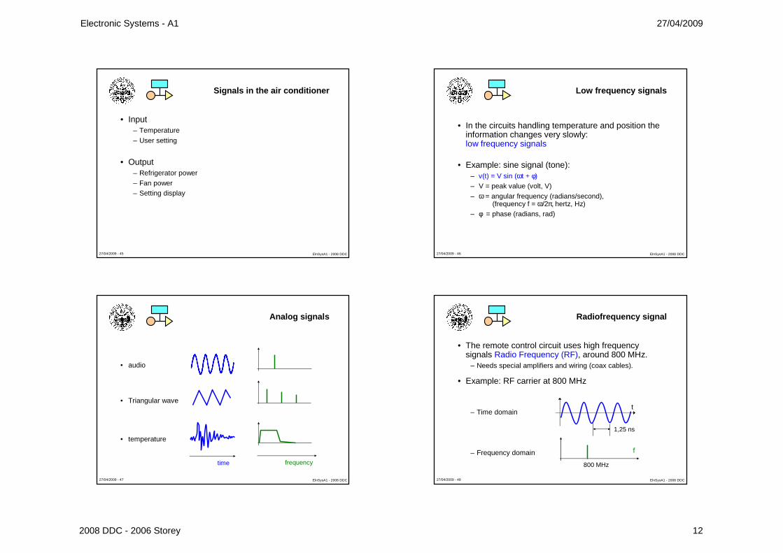
Various types of signals
• Analog/digital• High/low/very low level
– Mike vs loudspeaker
• Frequency range– Audio vs RF
• Waveform – Sinewave, squarewave
• Information encoding– Cell phones– Digital TV
• …
Electronic Systems - A1 27/04/2009
2008 DDC - 2006 Storey 12
27/04/2009 - 45 ElnSysA1 - 2008 DDC
Signals in the air conditioner
• Input– Temperature– User setting
• Output– Refrigerator power– Fan power– Setting display
27/04/2009 - 46 ElnSysA1 - 2008 DDC
Low frequency signals
• In the circuits handling temperature and position the information changes very slowly: low frequency signals
• Example: sine signal (tone):– v(t) = V sin (ωt + φ)– V = peak value (volt, V)– ω = angular frequency (radians/second),
� All systems also add noiseto the signals that pass through them.
� Unlike distortion, noise israndom and not repeatable.
� Noise cannot be removed from analog signals
� With proper techniques, noise can be removedfrom digital signals.
Noise
27/04/2009 - 63 ElnSysA1 - 2008 DDC
Analog signal degradation
• Any processing or amplification step adds noise.
• For an analog signal the noise represents a not recoverable information loss.
27/04/2009 - 64 ElnSysA1 - 2008 DDC
Digital signal degradation
• In a digital signal degradation caused by noise can be recovered, if limited within defined boundaries.
Electronic Systems - A1 27/04/2009
2008 DDC - 2006 Storey 17
27/04/2009 - 65 ElnSysA1 - 2008 DDC
Digital signal level restore
Thanks to amplitude discretization of digital signals, the levels can be restored to original values by comparison with a threshold
27/04/2009 - 66 ElnSysA1 - 2008 DDC
Digital signal recovery
• Digital signal can be recovered at regular intervals– Effects of noise do not cumulate
• Recovery allows to use long digital processing chains, to carry out complex operation
– Not possible with analog technique, due to noise cumulative effects
• To avoid information loss– Noise must be limited– Signal must be periodically rebuilt.
• Simulator of noise effects on Ulisse website: material � simulator and SW � segnale analogico/digitale con rumore
27/04/2009 - 67 ElnSysA1 - 2008 DDC
Towards external world
• Physical interfaces (transducers and actuators) handle in most cases analog signals
• The Electronic system uses analog signal to interact with the external world
ELECTRONICSYSTEM
ANALOG SIGNALS
27/04/2009 - 68 ElnSysA1 - 2008 DDC
A/D/A sequence
• Today electronics is mainly digital– signals must be translated from analog to digital, and then
from digital to analog:» ANALOG/DIGITAL (A/D) conversion» DIGITAL/ANALOG (D/A) conversion
ELECTRONIC SYSTEM
NUMERICSYSTEM
A/D D/A
ANALOG SIGNALS
Electronic Systems - A1 27/04/2009
2008 DDC - 2006 Storey 18
27/04/2009 - 69 ElnSysA1 - 2008 DDC
ELETTRONICSYSTEM
Analog ���� Digital ���� Analog
• Most part of electronic systems includes:– interfaces towards the analog external world (front-end)– A/D conversion– Numeric signal handling– D/A conversion – interfaces towards the analog external world (back-end)
ADC
Numeric system DAC
Actuators and analog
back-end
Sensors and analog
front-en
27/04/2009 - 70 ElnSysA1 - 2008 DDC
Changes in electronic systems
• Electronics systems are moving towards digital
A/D
Numericsystem
D/A Actuat
Sens
A/D
Numeric system
Actuators and analog
back-end
Sensors and analog
front-end
timeD/A
27/04/2009 - 71 ElnSysA1 - 2008 DDC
Electronics is going towards digital
• Only digital techniques allow complex processing– They do not cumulate noise– Digital integrated circuit have higher complexity then analog
ones
• Automatic tools for design and testing of digital ICs are available
– Digital ICs have lower cost
• The behavior of a digital circuit can be easily modified