International Journal of Enterprise Computing and Business Systems International Journal of Enterprise Computing and Business Systems International Journal of Enterprise Computing and Business Systems International Journal of Enterprise Computing and Business Systems ISSN (Online) : 2230 ISSN (Online) : 2230 ISSN (Online) : 2230 ISSN (Online) : 2230-8849 8849 8849 8849 http://www.ijecbs.com Vol. 1 Issue 2 July 2011 1 LENS SHAPING FOR IMPULSE ANTENNA USED FOR MICROWAVE APPLICATIONS N.S.Murthy Sharma #1 , M.Chakrapani 1 and M.L.N.acharyulu *2 # Electronics and communications Engineerig SV Institute of Engineering and Technology Moinabad(M) R.R.District :501504 B.M.College of Technology Indore, 423001, India, ABSTRACT- This paper considers a novel class of antennas namely impulse radiating antennas(IRA) Mainly the Electromagnetic simulation of dielectric lens. The lens is integrated part of an impulse radiating antenna. The corresponding design equations are implemented by using MATLAB software. The results are presented at various cases. This work can be extended for arrays of IRA for multi band communication applications Keywords: Dielectric lens, Impuse antenna, MATLAB 1 Introduction Impulse radiating antennas are a class of antennas especially suited for radiating very fast Pulses in a narrow beam. The geometry of an impulse radiating reflector antenna fed by conical TEM feed is shown in Fig.1 A typical impulse radiating antenna consists of a high voltage pulser fed by a co-Axial transmission line. The pulser excites a conical TEM feed which is terminated at Figure 1. An Impulse Radiating Reflector antenna fed by conical TEM transmission lines
Transcript
International Journal of Enterprise Computing and Business Systems International Journal of Enterprise Computing and Business Systems International Journal of Enterprise Computing and Business Systems International Journal of Enterprise Computing and Business Systems
N.S.Murthy Sharma #1 , M.Chakrapani1 and M.L.N.acharyulu *2
# Electronics and communications Engineerig
SV Institute of Engineering and Technology
Moinabad(M) R.R.District :501504
B.M.College of Technology
Indore, 423001, India,
ABSTRACT- This paper considers a novel class of antennas namely impulse radiating antennas(IRA) Mainly the Electromagnetic simulation of dielectric lens. The lens is integrated part of an impulse radiating antenna. The corresponding design equations are implemented by using MATLAB software. The results are presented at various cases. This work can be extended for arrays of IRA for multi band communication applications Keywords: Dielectric lens, Impuse antenna,
MATLAB
1 Introduction Impulse radiating antennas are a class of antennas especially suited for radiating very
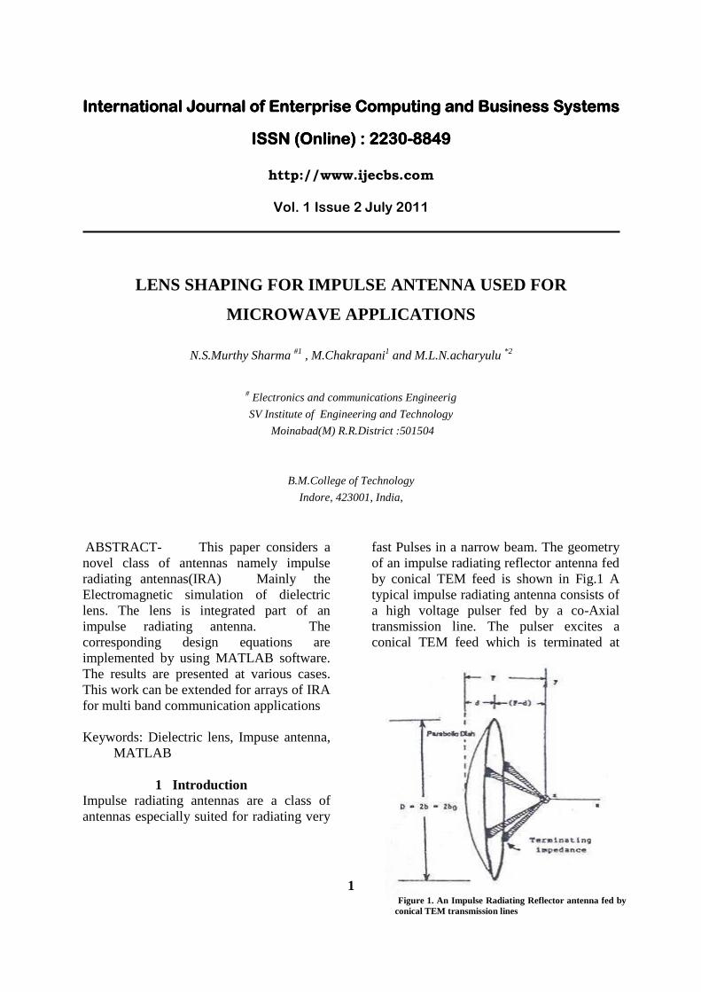
fast Pulses in a narrow beam. The geometry of an impulse radiating reflector antenna fed by conical TEM feed is shown in Fig.1 A typical impulse radiating antenna consists of a high voltage pulser fed by a co-Axial transmission line. The pulser excites a conical TEM feed which is terminated at
Figure 1. An Impulse Radiating Reflector antenna fed by conical TEM transmission lines
International Journal of Enterprise Computing and Business Systems International Journal of Enterprise Computing and Business Systems International Journal of Enterprise Computing and Business Systems International Journal of Enterprise Computing and Business Systems
the parabolic reflector by appropriate matching resistors. Hence the pulser is activated for a very short duration and an impulse current density is induced in the TEM feeds. A spherical TEM waves originates from the apex to the feed and impinges on the aperture. The process results in a delta function response in the far field. These types of antennas have application as high power pulse radiators, transient radars, and operating with many frequencies with large band ratios. These antennas handle multiple signals for communications, radar and warfare [1]. Prior to the problem of the context, TEM feed simulation is also essential for this antenna. Factors governing the design of an optimum Impulse radiating antenna and relevant status of the work are discussed elsewhere[1]. The electric field radiated on the boresight axis of the antenna is proportional to the rate of rise of the applied voltage .hence this rate of rise is to be maximized .this leads to physically small switches operating in a high pressure gas tends to appropriate 1015v/sec.The combination of requiring physically small switches ,high voltage and busy vise times implies the use of electromagnetic lens and switch version the lens is made of oil medium which serves the dual purposes of the high voltage
insulation and ensuring a spherical TEM wave launch on to the feed plates.
In this paper ,the dielectric-lens designs are considered for the specific case of launching an approximate spherical TEM wave onto an impulse radiation antenna (IRA).Restrictions on launch angles are derived yielding a range of acceptable lens parameters. An equal transit-time condition on ray paths is imposed to ensure the correct spherical wave front. Some reflection , ideally small ,at the lens boundary are allowed .illustrations and numerical tables are presented from which examples of these lenes may be constructed .
II Dielectric lens in the region of Impulse
radiating antenna
The Fig.2 shows dielectric lens along with the pulser located at the launch region of Impulse radiating antenna .The purpose of the lens is to reuse that the wave front of the TEM wave in the air region outside the lens medium is spherical with its origin at the focal point of the parabolic reflector which also the true apex of the feed plates. Assuming that the switch located at z=-zs
Closes at a time so that increased,an ideal source turns on at t=0 at the apex and the wave propagates in air. The lens medium ( 0 is in a container whose dielectric constant
International Journal of Enterprise Computing and Business Systems International Journal of Enterprise Computing and Business Systems International Journal of Enterprise Computing and Business Systems International Journal of Enterprise Computing and Business Systems
is same as air) also helps in high voltage stand off .also the lens causes the characteristics impedance of the conical transmission line by reciprocal of the dielectric constant of lens medium except for small changes due to causes.the relative dielectric constant (εr) used increases at early time of the field due to the transmission coefficient.
Necessary Theotical Back Ground
Consider an impulse radiating antenna (IRA) in the form of a paraboloidal reflector fed by a conical transmission line suitable for guiding a spherical TEM wave [2] as indicated in F\g2.the paraboloidal reflector is assumed too have a circular edge of radius a with diameter (D) as double of its radius
(a). The apex of the conical feed is located at focal distance (F) from the center of the reflector , The angle from the apex of the conical transmission line (focalpiont )to the edge of the reflector is [3]
1 12max
2 2cot 2 tan
8 2
F D a
D F Fθ − − = − =
(1)
.Above approximation hold good by treating F larger than D.Centering the coordinate system on the conical apex, then 0<θ<θ2max represents the range of interest of angles for launching an electromagnetic wave toward the reflector, the axis of rotation symmetry of this reflector being taken as the z axis in the usual spherical coordinates.
Figure2: Block diagram Electromagnetic Lens in a conical transmission line fed by a voltage source
International Journal of Enterprise Computing and Business Systems International Journal of Enterprise Computing and Business Systems International Journal of Enterprise Computing and Business Systems International Journal of Enterprise Computing and Business Systems
As one extrapolates the desired wave on the TEM launch back toward the apex the electric field is larger and larger, until at some position before reaching the apex electrical breakdown conditions are exceeded. This is especially important in transmission where high voltages( and corresponding high powers) are desired. If the required spacing of the conical conductors at this cross section is larger than radian wavelengths at the highest frequencies of interest, or larger than some small rise time(times the speed of light ) of interest, then care needs to be taken in synthesizing the fields at this cross section(on some aperture spherical surface). One way to achieve the increased dielectric strength, allowing one to extrapolate the desired wave back to smaller cross sections , where a switch or some other appropriate electrical source is located, is by the use of a dielectric lens .Various kinds of lenses can be considered, including those which in an ideal sense can launch the exact form of spherical TEM wave desired . Here we consider a simple uniform dielectric lens which meets the equal-time requirement for the desired spherical wave, but has some (preferably small) reflections at the lens boundary which distort some what the desired spatial distribution (TEM) of the fields on the aperture sphere. The lens region in; Fig.2 is shown on an expanded scale in Fig.3.
The apex, or focal point for spherical wave (outside the lens) launched toward the
reflector, is the origin ( 02 =τ ) of the 2τ coordinate system. Here we illustrate some cut at a constant ø ,the lens being a body of revolution. .Defining relative permittivity of lens medium as ratio of permittivity out side and inside of the lens, It is understood the medium being nonmagnetic with the permeability 0µ both inside and outside of
the lens be.T he outer permittivity is often be taken as 0∈ in practical cases, and the
lens permittivity ‘ 1∈ ’ is considered t for dielectrics of interest such as for polyethylene or transformer oil is 2.26. The
max2θ is now the maximum of 2θ ,
describing the rays leaving the lens toward the reflector. Inside the lens there are rays emanating from (x, y, z) = [0,0,( 12 ll − )] (2)
Figure3: Reflector of
IRA
International Journal of Enterprise Computing and Business Systems International Journal of Enterprise Computing and Business Systems International Journal of Enterprise Computing and Business Systems International Journal of Enterprise Computing and Business Systems
with the angle with respect to the z axis. With the inside and outside rays meeting at the lens boundary the various angles are related. Corresponding to max2θ there is
also a max1θ with 0 ≤ 1θ ≤ max1θ . For
normalization purposes the position on the lens boundary for this outermost ray of interest is defined as having a cylindrical radius h . For later use this position will remain fixed for a given max2θ for various
shapes of the lens boundary given by varying max1θ . The scaling lengths are
related by the focal length formula 1
21
11
0−−− += lll (3)
So given 1l and 2l one finds 0l and 0l is
scaled in units of h (See Fig.4).
III. Restrictions on launch angles
As indicated in Fig.2, there is a potential problem with the lens concerning the fatness (extent of cylindrical radiusψ ) and the
maximum angle max2θ for launching the
spherical wave outside the lens. In particular as 2θ approaches max2θ from below, the
lens boundary should not cross over the outermost ray of interest defined by
2θ = max2θ . Referring to Fig.4, then we
require that the slope of the lens boundary, where the boundary meets this ray, should satisfy
max2max1 θθ ≤ (4)
The radius of the lens boundary bψ can be
allowed to exceed h, still meeting the restriction of above equation..
clc 2θθ = (5)
International Journal of Enterprise Computing and Business Systems International Journal of Enterprise Computing and Business Systems International Journal of Enterprise Computing and Business Systems International Journal of Enterprise Computing and Business Systems
define critical angles(subscript “c”). This case is illustrated in Fig.3.5, where the region where the critical ray meets the boundary is expanded. Appealing to Snell’s law in which the phase velocities of the waves in the two media are matched along the boundary gives
( ) ( )1 2sin sini t
ψ ψ∈ = ∈ (6)
Using (4) we have, ψt=900, i.e, the wave in medium 2, propagating parallel to the lens boundary. By geometric construction, and simplification,
( )-1θ =θ +cos1c 2c r
∈ (7)
To estimate the principle value for the cos -1 in (7), needs noting that cc 21 θθ ≤ in the
construction of Fig(5)Noting that a transmission angle 2/πψ ≤t ,gives
θ θ1max 2max
≤ as an acceptable lens
boundary in Fig 4,
( ) ( )sin cos θ θ1max 2maxiψ = − ≥ r∈ ,
≤− max2max1 θθ ( )1cos r− ∈ (8)
If max2max θθ ≤l , but then the geometrical
construction in Fig 4 and Fig54 do not apply and the lens boundary becomes concave to the right. For present considerations, as max1θ describes the path of the
conical-transmission-line conductors in the lens region, a region which lowers the characteristic impedance from that of the conical transmission line outside the lens, our interests centers on
1maxθ near 2/π
that maximizes the transmission-line characteristic impedance in lens. There is other consideration as well such as high voltage (breakdown) in the lens closer to the apex at (2) that push in the same direction. In this, concerning max1θ is limited to
12max 1max 2max
1min , cos
2r
πθ θ θ −
≤ ≤ + ∈
(9)
Figure4 : lens for launching spherical wave
International Journal of Enterprise Computing and Business Systems International Journal of Enterprise Computing and Business Systems International Journal of Enterprise Computing and Business Systems International Journal of Enterprise Computing and Business Systems
For large dielectric constant, the allowable range of max1θ is constrained close to max2θ
Special Case of max2θθ = Spherical Lens
A very simple lens is that of a sphere of radius ‘b’ centered on the origin with
blll === 012 2 , 2 1 1max 2max,θ θ θ θ= =
(11) In this case, if the conical transmission line medium 2 has a characteristic impedance
2cZ , then continuing the conical conductors
back into the lens gives a characteristic impedance there of
1 2
1c c
r
Z Z=∈
(12)
While the TEM modal distribution is the same on both sides of the lens boundary there is a reflection at the boundary with reflection coefficient
2 1
2 1
1
1
rc c
c c r
Z Z
Z Z
− ∈ −Γ = =+ ∈ +
(13)
And transmission coefficient 2
T1
r
r
∈=
∈ +
(14) For 26.2=∈r 0.20, 1.20TΓ ≈ ≈ The reflected wave in turn reflects off the source point(apex) with an amplitude dependent on the source impedance, say-1 reflection for a short circuit. This reflection in turn passes through the lens boundary as another spherical TEM wave.
Note that in principle the lens should
be a complete sphere(4π steradians, volume
Figure .5: Restriction of lens Boundary to inside
outermost Ray of interest
International Journal of Enterprise Computing and Business Systems International Journal of Enterprise Computing and Business Systems International Journal of Enterprise Computing and Business Systems International Journal of Enterprise Computing and Business Systems
3/4 3bπ ) for the above analysis exactly apply. Otherwise, the missing portions of the lens can introduce other modes which affect the fields at the observer with max22 θθθ ≤≤ , complicating the
waveform during the times of significance for reflections.
This points to a possible disadvantage for this kind of spherical lens. Other lens shapes, while meeting the equal-time
requirement for the first wave through the lens going into a spherical wave outside the lens, can break up the wave front for successive waves by sending non-spherical waves back from the lens boundary which need not ( in large part) converge on the source point.
Brewester angle considerations
Fig ure7: Total Transmission of E
Fig ure8 : lens shape for F/D = 0.3
International Journal of Enterprise Computing and Business Systems International Journal of Enterprise Computing and Business Systems International Journal of Enterprise Computing and Business Systems International Journal of Enterprise Computing and Business Systems
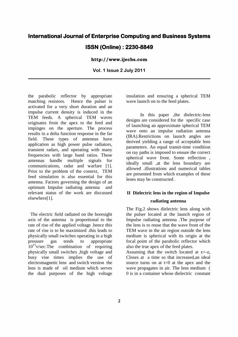
One can reduce reflections at the lens boundary by changing the direction of incidence for appropriate polarization (E wave) by use of Brewster angle considerations [4,5,7].Referring to Fig..6, and using a subscript “B” for this case we have[1]
°==+ 902
πψψ tBiB
(15) For
26.2=∈r
,°≈ 6.33iBψ
°≈ 4.56tBψ
Noting that the angle tBψ of the transmitted
ray is greater than 00 (transmission of normally incident wave) but less than 090 (corresponding to transmission parallel to the lens boundary as in Fig.5.), then for
max1θ chosen near the critical case there are
max11 θθ < and max22 θθ < thath satisfy s Brewster-angle condition. So increasing max1θ above max2θ , and critical angles in
Table .1: Lens shape data for F/D=0.3, with 0 ≤ 1θ ≤ max1θ
International Journal of Enterprise Computing and Business Systems International Journal of Enterprise Computing and Business Systems International Journal of Enterprise Computing and Business Systems International Journal of Enterprise Computing and Business Systems
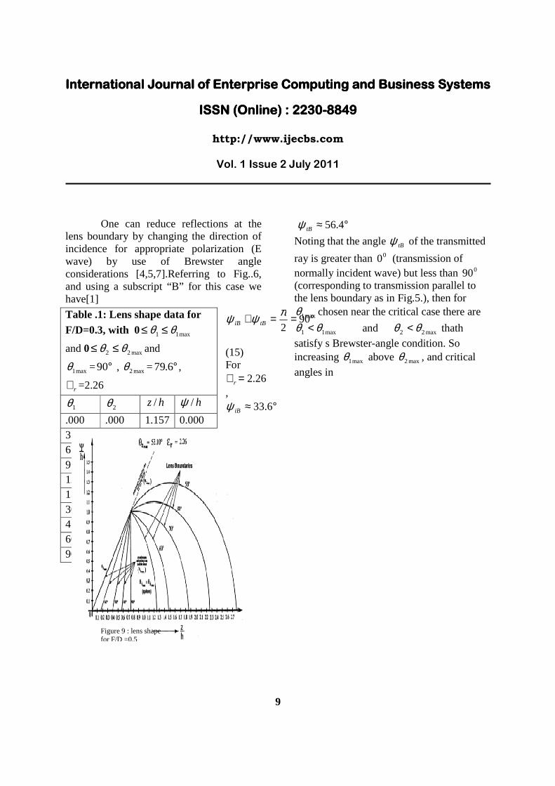
both medium are same, one may make some of the rays have a better transmission through the lens boundary. Lens shaping
To obtain the lens boundary curve we need to compute the coordinates z and ψ as a
function of 2θ (and 1θ ).The geometry in Fig4,[1] then yields the result
( ) ( )( ) ( )21
112
tantan
tan
θθθ
−−
=ll
z (16)
( ) ( ) ( ) ( )( ) ( )21
21122 tantan
tantantan
θθθθθψ
−−
==ll
z
(17)
The above two equations form basis for lens
shaping.
Results and discussion In Figures 7 through 8we show various lens boundaries corresponding to values of F/D corresponding to 0.3,0.4,and 0.5 respectively. As expected, we obtain larger for larger values of F/D. In Figure 9, the results obtained correspond to the
Table .2: Lens shape data for F/D=0.4, With 0 ≤ 1θ ≤ max1θ and
International Journal of Enterprise Computing and Business Systems International Journal of Enterprise Computing and Business Systems International Journal of Enterprise Computing and Business Systems International Journal of Enterprise Computing and Business Systems
choice of F/D=0.4.For this value, °= 01.64max2θ and lens boundary
curves are obtained for choices of
max1θ equal to °°° 90,80,70 as well as max2θ
itself. In tables 1, 2 and 3 numerical data is presented for the case max1θ = °90 with
F/D=0.3,0.4,and 0.5 by allowing 1θ and
2θ to vary up to their maximum values and calculating the coordinates z/h and h/ψ .
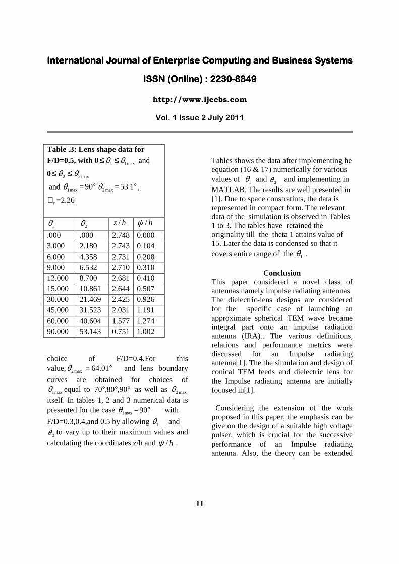
Tables shows the data after implementing he equation (16 & 17) numerically for various values of 1θ and
2θ and implementing in MATLAB. The results are well presented in [1]. Due to space constratints, the data is represented in compact form. The relevant data of the simulation is observed in Tables 1 to 3. The tables have retained the originality till the theta 1 attains value of 15. Later the data is condensed so that it covers entire range of the 1θ .
Conclusion This paper considered a novel class of antennas namely impulse radiating antennas The dielectric-lens designs are considered for the specific case of launching an approximate spherical TEM wave became integral part onto an impulse radiation antenna (IRA).. The various definitions, relations and performance metrics were discussed for an Impulse radiating antenna[1]. The the simulation and design of conical TEM feeds and dielectric lens for the Impulse radiating antenna are initially focused in[1]. Considering the extension of the work proposed in this paper, the emphasis can be give on the design of a suitable high voltage pulser, which is crucial for the successive performance of an Impulse radiating antenna. Also, the theory can be extended
Table .3: Lens shape data for F/D=0.5, with 0 ≤ 1θ ≤ max1θ and
International Journal of Enterprise Computing and Business Systems International Journal of Enterprise Computing and Business Systems International Journal of Enterprise Computing and Business Systems International Journal of Enterprise Computing and Business Systems
for arrays of IRA for multi band communication applications.
Acknowledgment
Part of the work proposed is carried out as P.G. Project at Center for Microwave Excellence of University college of Engineering of Osmania University. The director of the center Dr. V.S. Prasanna Rajan, Deserves thanks for his encouragement. Director of S.V.Group of Instutions Dr. Dinakar Bhosale is incredible for his valuable guidance. Also, Principal and Director of B.M.College of Technology, Inodore of Madhapradesh is
References
M.L.N.Acharyulu , “Electromagnetic simulation and Design of a Conical TEM and dielectric lens for an Impulse Radiating Antenna”, M.E. Dissertation, Osmania University, 2006. C. E. Baum, “Radiation of Impulse-Like Transient Fields,” Sensor and Simulation Note 321, 1989. Gilbert, J.G. Shovlin, R,.J, “High speed transmission line fault impedance calculation using a dedicated minicomputer” IEEE Transactions on Power Apparatus and Systems, Volume : 94 , Issue:3, March, 2006. C.E.Baum,”Impedance and field distributions fot parallel plate transmission line simulators,” Sensor and simulation
note 21, June 1966 C.E.Baum, “transient analysis,ultrawide band short pulse Electromagnetics “,New York,plenum,pp.129-138. 1997