Instruction Manual TOP COVER Electronic Total Station R-315(N)/R-325(N)/R-335(N)/R-322(N)/R-323(N)/R326 Special Functions PTL Software Ver.346 PENTAX Industrial Instruments Co., Ltd. Document Ver.1.03 R-300 SERIES ®
PENTAX Industrial Instruments Co., Ltd. is a sole proprietor of the PowerTopoLite software. The PowerTopoLite software and publication or parts thereof, may not be reproduced in any form, by any method, for any purpose. PENTAX Industrial Instruments Co., Ltd. makes no warranty, expressed or implied, including but not limited to any implied warranties or merchantability or fitness for a particular purpose, regarding these materials and makes such materials available.
Document Ver.1.03: July. 2004
PTL Software V.346
2
Display and Keyboard Basic display and keyboard of RRRR-300 series are described below, and the function keys of
PowerTopoLite are described at “2. ACCESSING THE POWERTOPOLITE”. The description concerning only Reflectorless type, R-315N/R-325N/R-335N/R-322N/R-323N, is
put in ( ).
Operation Key Key Description [POWER] ON/OFF of power supply [ESC] Returns to previous screen or cancels an operation. [Illumination] Turns the illumination of the LCD display and telescope reticle on and
off. [ENT] Accepts the selected , highlighted, choice or the displayed screen value. [Laser] Displays the laser plummet *1, Electronic vial function, and the LD point
screen when you push the laser plummet/electronic vial key. (Refer to "2.5 LD point function", "3.2 Laser plumb", and "3.5 Leveling with electronic vial" of "Instruction Manual"). *1: Only the product with the laser plumb function
[Alphanumeric] At the numerical value screen, the numerical value and the sign '.' displayed are input. The English characters printed right under numeric of each key are input.
[HELP] Pressing [lLLU]+[ESC] causes a help menu to appear in A MODE or B MODE or causes a help messages to appear.
Power supply key Function keys Illumination key ESC key Laser plumb &
Electronic vial
Alphanumeric and +/- key
Enter key
PTL Software V.346
3
Function key
Display F. Key Description Mode A [MEAS] F1 Pressing this key one time measures the distance in normal
mode(another measurement type can be selected by Initial Setting 2.) [MEAS] F1 Pressing this key twice measures the distance in coarse
mode(another measurement type can be selected by Initial Setting 2.) [TARGET] F2 Select the target type by following order.
SHEET / PRISM / REFRECTORLESS (Reflectorless type instrument) SHEET/ PRISM (Prism type instrument)
[0 SET] F3 Resets the horizontal angle to 0° 0' 0" by pressing twice. [DISP] F4 Switches the display composition in the order
[MODE] F5 Switches the screen between MODE A and MODE B. Mode B [S.FUNC] F1 PowerTopoLite Special Functions [ANG SET] F2 Brings up the angle setting screen for setting angle-related
parameters (H.ANGLE/%GRADE, H.ANGLE INPUT and R/L REVERSE).
[HOLD] F3 Pressing this key twice retains (holds) the horizontal angle shown on the display.
[CORR] F4 Brings up the screen for changing the Target constant, Temperature, Pressure setting.
[MODE] F5 Toggles the screen between MODE A and MODE B. Other functions [ ] F1 Moves the cursor to the left. [ ] F2 Moves the cursor to the right. [ ] F1 Goes back five Items on the screen [ ] F2 Goes forward five items on the screen. [ ] F3 Moves the cursor up [ ] F4 Moves the cursor down RETICLE F3 Changing the Reticle illumination when pressing Illumination key LCD F4 Changing the LCD contrast when pressing Illumination key ILLU F5 Changing the LCD illumination when pressing Illumination key [CLEAR] F5 Clear the figure [SELECT] F5 Open the selection window
The Function keys of each PowerTopoLite function are described at “ACCESSING THE POWERTOPOLITE” and at the each function.
Display combination of Mode A or Mode B
Function MODE A MODE B F1 MEAS S.FUNC F2 TARGET ANG SET F3 0 SET HOLD F4 DISP CORR F5 MODE MODE
Mode A or Mode B is switched by pressing [F5] [MODE].
PTL Software V.346
4
Alphanumetric Input The point name etc. is input by the alphanumeric keys as following.
Key Letter under Key Letter & Figure order to input
[0] [@][.][_][-][:][/][0]
[1] PQRS [P][Q][R][S][p][q][r][s][1]
[2] TUV [T][U][V][t][u][v][2]
[3] WXYZ [W][X][Y][Z][w][x][y][z][3]
[4] GHI [G][H][I][g][h][i][4]
[5] JKL [J][K][L][j][k][l][5]
[6] MNO [M][N][O][m][n][o][6]
[7] [ ][?][!][_][ ][^][|][&][7]
[8] ABC [A][B][C][a][b][c][8]
[9] DEF [D][E][F][d][e][f][9]
[.] [.][,][:][;][#][(][)]
[+/-] [+][-][*][/][%][=][<][>]
PTL Software V.346
5
CONTENTS Copyright Display and Keyboard Memories in the Instrument Relations between memories and each function
(TOP COVER) Display and Keyboard 2 Operation Key 2 Function key 3 Display combination of Mode A or Mode B 3 Alphanumetric Input 4
1. INTRODUCTION 7 1.1 Introduction 7 1.2 Before using the PowerTopoLite manual 7
2. ACCESSING THE POWERTOPOLITE 9 2.1 How to access the PowerTopoLite 9 2.2 Allocation of each PowerTopoLite Function key 10 2.3 Typical Function keys of the PowerTopoLite 11
3. FILE MANAGER 12 3.1 Information of the remaining memory available 12 3.2 Creation of a new Job 12 3.3 Selection of a Job name 13
3.3.1 Selection of a Job 13 3.3.2 Selection by a Job name input 13
3.4 Deletion of a Job name 14 3.4.1 Deletion from a Job list 14 3.4.2 Deletion from a Job name search 15
4. MEASURE 16 4.1 Station setup [By Rectangular Coordinates] 17
4.1.1 Point name, PN, input 17 4.1.2 Coordinates, X, Y, Z, IH, and PC input 17
4.2 Station Orientation 21 4.2.1 Station orientation 21
4.3 Measuring 22 4.4 Point Code 23 4.5 Remote, Offset, Station, H. angle function 25
4.5.1 Remote 25 4.5.2 Offset 26 4.5.3 Station 28 4.5.4 H. angle 28
4.6 Station setup [ By Polar Coordinates] 29 4.6.1 Point name, PN, input 29 4.6.2 IH, TEMP, PRESS, ppm and PC input 29
4.8 Measuring 32 4.9 Offset 34
5. VIEW AND EDIT 35 5.1 Graphical View 35 5.2 Create the Rectangular Point 36 5.3 Edit the Data 37
6. FREE STATIONING 38 6.1 Stationing by more than 3known points 38
PTL Software V.346
6
6.2 Stationing by two known points 41
7. STAKE OUT 39 7.1 STAKE OUT 39 7.2 POINT TO LINE 46
8. CALCULATIONS 49 8.1 COGO 49
8.1.1 INVERSE 49 8.1.2 POINTS COORDINATES 49
8.1.2.1 Point Coordinates, Distance and H. angle 49 8.1.2.2 Distance and H. angle 56 8.1.2.3 H. angle input 57
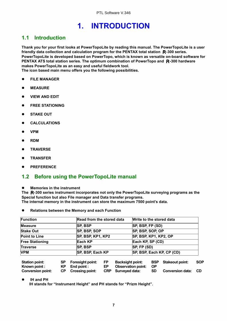
1. INTRODUCTION 1.1 Introduction Thank you for your first looks at PowerTopoLite by reading this manual. The PowerTopoLite is a user friendly data collection and calculation program for the PENTAX total station RRRR-300 series. PowerTopoLite is developed based on PowerTopo, which is known as versatile on-board software for PENTAX ATS total station series. The optimum combination of PowerTopo and RRRR-300 hardware makes PowerTopoLite as an easy and useful fieldwork tool. The icon based main menu offers you the following possibilities. FILE MANAGER
MEASURE
VIEW AND EDIT
FREE STATIONING
STAKE OUT
CALCULATIONS
VPM
RDM
TRAVERSE
TRANSFER
PREFERENCE
1.2 Before using the PowerTopoLite manual Memories in the instrument
The RRRR-300 series instrument incorporates not only the PowerTopoLite surveying programs as the Special function but also File manager and Data transfer programs. The internal memory in the instrument can store the maximum 7500 point’s data. Relations between the Memory and each Function
Function Read from the stored data Write to the stored data Measure SP, BSP SP, BSP, FP (SD) Stake Out SP, BSP, SOP SP, BSP, SOP, OP Point to Line SP, BSP, KP1, KP2 SP, BSP, KP1, KP2, OP Free Stationing Each KP Each KP, SP (CD) Traverse SP, BSP SP, FP (SD) VPM SP, BSP, Each KP SP, BSP, Each KP, CP (CD) Station point: SP Foresight point: FP Backsight point: BSP Stakeout point: SOP Known point : KP End point : EP Observation point: OP Conversion point: CP Crossing point: CRP Surveyed data: SD Conversion data: CD IH and PH
IH stands for “Instrument Height” and PH stands for “Prizm Height”.
PTL Software V.346
8
The PowerTopoLite manual mainly describes the RRRR-300 special functions, and the basic operations are described in the (basic) RRRR-300 manual. And, therefore, refer to the RRRR-300 basic manual regarding the RRRR-300 general instrument operations.
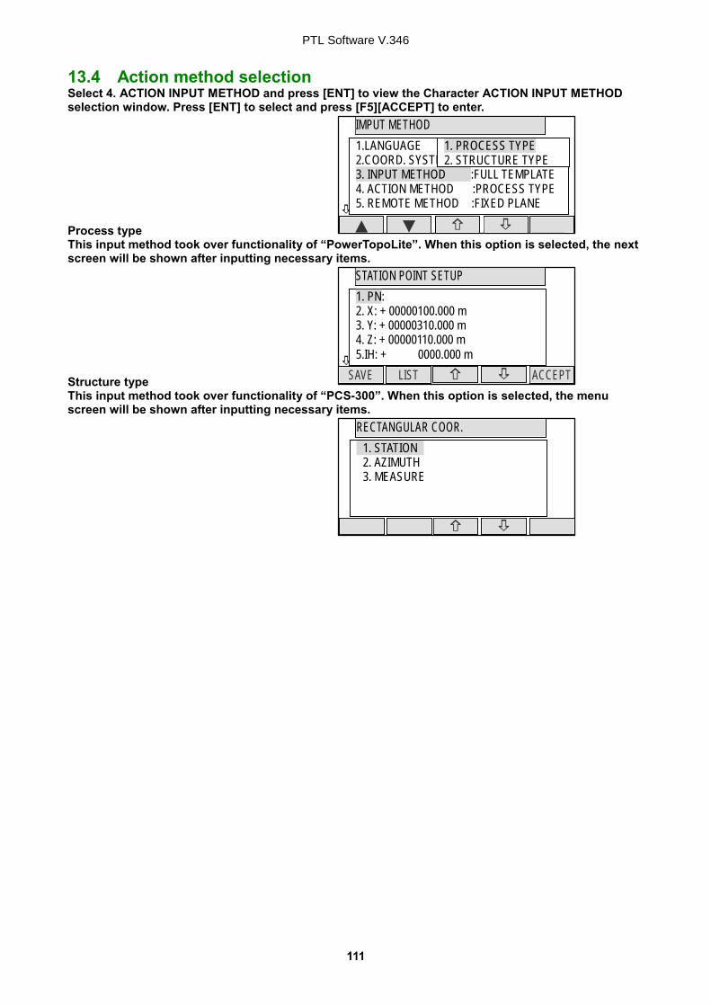
The PowerTopoLite screens vary with the selections of the “Preference”. The factory default settings of the Preference are shown there. It is also possible to select “Process type” that took over functionality of “PowerTopoLite” or “Structure type” that took over functionality of “PCS-300” in ”Action Method Selection”.
The RRRR-300 series instrument has a Job name of “PENTAX” as its default setting. And, therefore, each data is stored in the “PENTAX” unless another new Job name is created. When another Job name is created, each data is stored in the new Job name.
The input range of the X, Y and Z Coordinate is “00000000.000” – “99999999.998”.
The input range of the Instrument and Prism height is “0000.000” – “9999.998”.
The PC, PointCodeList, is added to the PN, Coordinates X, Y, Z and IH (PH or HI) and you can
input your desired attributes for the point. If you have PointCodeList in the job named “PointCodeList”, you can easily select one of the PointCode from the list or edit one of them after pressing [ENT]. Please, note that Point Code, which is saved in the other job can not be refered as a list.
There are two Coordinates types of Rectangular and Polar. The VO, TO offset and the remote
measurement are possible when you select the Rectangular Coordinates. When you measure in EDM SETTINGS of COARSE TRACKING, the RRRR-300 displays a distance
value to two decimal places. However, distance data of polar coordinates are displayed by EDIT function to three decimal places even, and sent to four decimal place. So, “ 0 “ or “ 00 ” is added to the distance data after the third decimal point in COARSE TRACKING mode.
For example Displayed value: 123.45 Displayed by EDIT: 123.450 Sent polar data: 123.4500
Rectangular coordinates is displayed, stored, and sent to three decimal place even if in
COARSE TRACKING or FINE MEASURE mode. You can change the distance measurement mode during measuring operation by pressing the
EDM key at the MEASURE and VPM functions. The same Point Name of the plural polar points can be saved.
PTL Software V.346
9
MODE B
CORR MODE ANG SET HOLD S.FUNC
H.angle 123° 45’ 25”
H.dst
V.dst
PowerTopoLite
RDM PAGE CALC VPM STAK
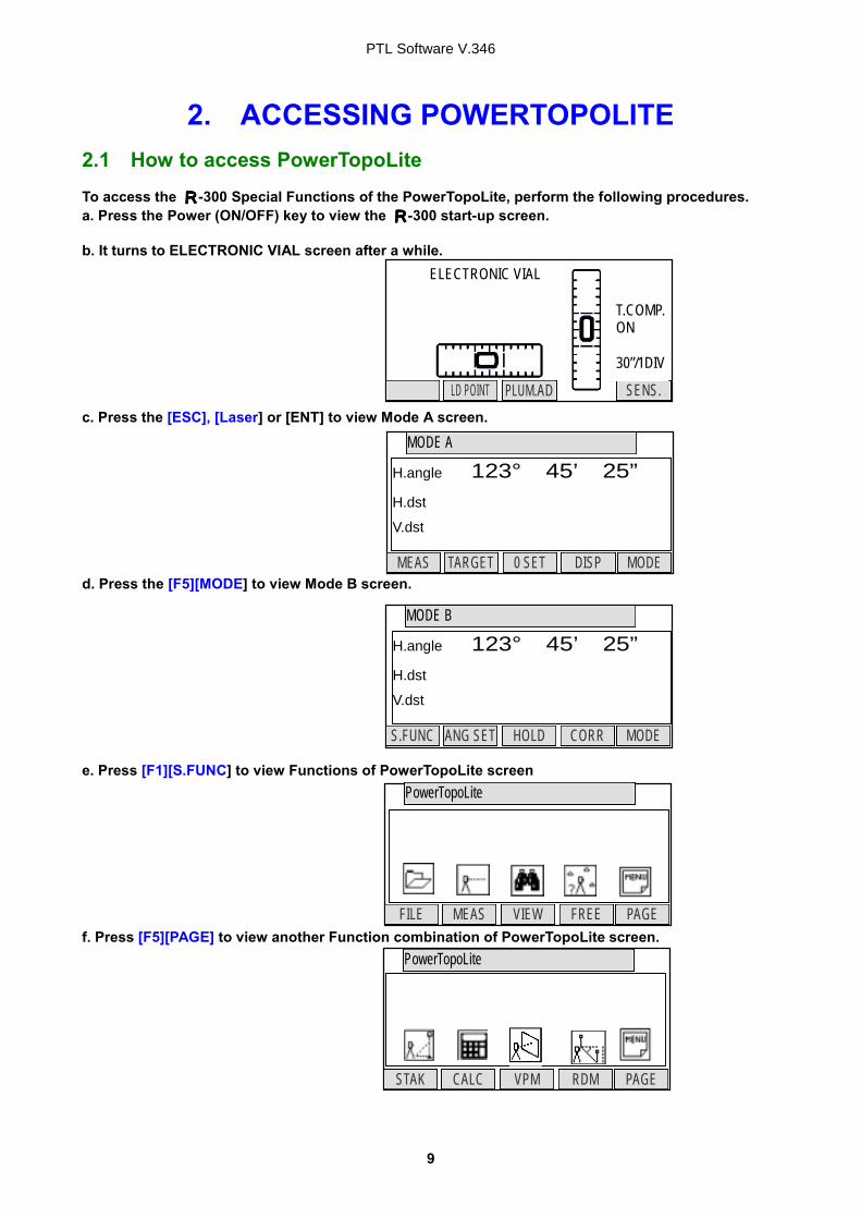
2. ACCESSING POWERTOPOLITE 2.1 How to access PowerTopoLite To access the RRRR-300 Special Functions of the PowerTopoLite, perform the following procedures. a. Press the Power (ON/OFF) key to view the RRRR-300 start-up screen. b. It turns to ELECTRONIC VIAL screen after a while. c. Press the [ESC], [Laser] or [ENT] to view Mode A screen. d. Press the [F5][MODE] to view Mode B screen. e. Press [F1][S.FUNC] to view Functions of PowerTopoLite screen f. Press [F5][PAGE] to view another Function combination of PowerTopoLite screen.
MODE A
DISP MODE TARGET 0 SET MEAS
H.angle 123° 45’ 25”
H.dst
V.dst
PowerTopoLite
FREE PAGE MEAS VIEW FILE
ELECTRONIC VIAL
SENS. LD POINT PLUM.AD
T.COMP. ON 30”/1DIV
PTL Software V.346
10
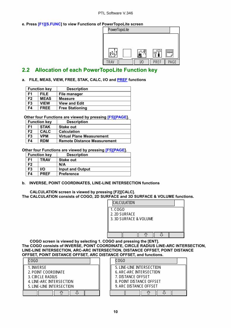
e. Press [F1][S.FUNC] to view Functions of PowerTopoLite screen 2.2 Allocation of each PowerTopoLite Function key a. FILE, MEAS, VIEW, FREE, STAK, CALC, I/O and PREF functions
Function key Description F1 FILE File manager F2 MEAS Measure F3 VIEW View and Edit F4 FREE Free Stationing
Other four Functions are viewed by pressing [F5][PAGE].
Function key Description F1 STAK Stake out F2 CALC Calculation F3 VPM Virtual Plane Measurement F4 RDM Remote Distance Measurement
Other four Functions are viewed by pressing [F5][PAGE].
Function key Description F1 TRAV Stake out F2 N/A F3 I/O Input and Output F4 PREF Preference
b. INVERSE, POINT COORDINATES, LINE-LINE INTERSECTION functions CALCULATION screen is viewed by pressing [F2][CALC]. The CALCULATION consists of COGO, 2D SURFACE and 3D SURFACE & VOLUME functions. COGO screen is viewed by selecting 1. COGO and pressing the [ENT]. The COGO consists of INVERSE, POINT COORDINATE, CIRCLE RADIUS LINE-ARC INTERSECTION, LINE-LINE INTERSECTION, ARC-ARC INTERSECTION, DISTANCE OFFSET, POINT DISTANCE OFFSET, POINT DISTANCE OFFSET, ARC DISTANCE OFFSET, and functions.
CALCULATION
1. COGO 2. 2D SURFACE 3. 3D SURFACE & VOLUME
COGO
1. INVERSE 2. POINT COORDINATE 3. CIRCLE RADIUS 4. LINE-ARC INTERSECTION 5. LINE-LINE INTERSECTION
2.3 Typical Function keys of PowerTopoLite Following function keys are typical ones of PowerTopoLite and each function key is described for each function of this Manual.
Function key Description ENTER Opens the input screen of Coordinate values etc. PAGE Views another function combination. SELECT Selects the Character and moves to next input at PN input etc. ACCEPT Enters the displayed values without new Coordinates value input etc. INPUT Inputs your desired Horizontal angle. BSP Views the BSP SETUP screen to input its Coordinates. SAVE Saves inputted data. ME/SAVE Measures and then saves inputted data. EDIT Changes the Point name or Prism height. REMOTE Views your aiming point Coordinates. OFFSET Views the Target Coordinates adding the offset values. STATION Returns to the STSATION POINT SETUP screen. H. ANGLE Returns to the STSATION POINT H.ANGLE SETUP screen. LIST Views the POINT SELECTION FROM THE LIST screen. ZOOM ALL Returns to original size. ZOOM IN Magnifies the graphics size. ZOOM OUT Reduces the graphics size. DISP Views point or point & graphic or point & point name or all. DELETE Views the POINT DELETION screen. FIND PN Views the PN search screen by inputting the Point name. ADD Allow you to add more points for the free stationing. CALC Starts the calculation of the free stationing. NEXT Views the next known point Coordinates setup screen. DATA Views the TARGET POINT screen. TARGET Selects the Target type EDM Selects the EDM settings ALL Selects all points of current job ORDER The order of selected points
PTL Software V.346
12
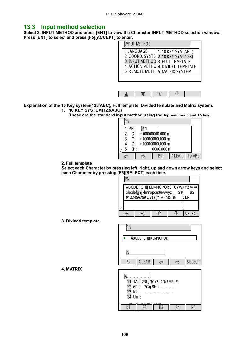
3. FILE MANAGER The Data storage memory status, creating a new Job name and the Selection and Deletion of a Job name are executed by this function. From the PowerTopoLite screen, press [F1][FILE] to view the FILE MANAGEMENT screen. 3.1 Information of the remaining memory available Press [ENT] to view INFORMATION screen. The remaining memory available and a JOB name PENTAX are viewed on the screen. The Job name “PENTAX” is a default setting. 3.2 Creation of a new Job Select 2. CREATE by down arrow key.
Press [ENT] to view the JOB NAME INPUT screen. The Job name input method can be selected by the “Input method selection” of the
“Preference”. This is the “10 KEY SYSTEM” input selection.
INFORMATION
PENTAX is the current job. 7499 points can be stored.
FILE MANAGEMENT
1. INFORMATION 2. CREATE 3. SELECT 4. DELETE
FILE MANAGEMENT
1. INFORMATION 2. CREATE 3. SELECT 4. DELETE
FILE MANAGEMENT
CLEAR TO 123 BS
1. INFORMATION 2. CREATE 3. SELECT 4. DELETE
PENTAX
PTL Software V.346
13
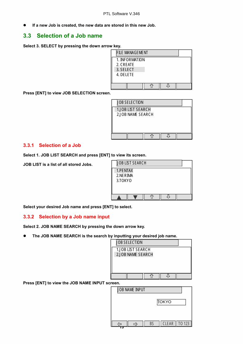
If a new Job is created, the new data are stored in this new Job. 3.3 Selection of a Job name Select 3. SELECT by pressing the down arrow key. Press [ENT] to view JOB SELECTION screen. 3.3.1 Selection of a Job Select 1. JOB LIST SEARCH and press [ENT] to view its screen. JOB LIST is a list of all stored Jobs. Select your desired Job name and press [ENT] to select. 3.3.2 Selection by a Job name input Select 2. JOB NAME SEARCH by pressing the down arrow key. The JOB NAME SEARCH is the search by inputting your desired job name.
Press [ENT] to view the JOB NAME INPUT screen.
JOB LIST SEARCH
1.PENTAX 2.NERIMA 3.TOKYO
JOB SELECTION
1.JOB LIST SEARCH 2.JOB NAME SEARCH
1.JOB LIST SEARCH 2.JOB NAME SEARCH
JOB NAME INPUT
CLEAR TO 123 BS
TOKYO
FILE MANAGEMENT 1. INFORMATION 2. CREATE 3. SELECT 4. DELETE
JOB SELECTION 1.JOB LIST SEARCH 2.JOB NAME SEARCH
PTL Software V.346
14
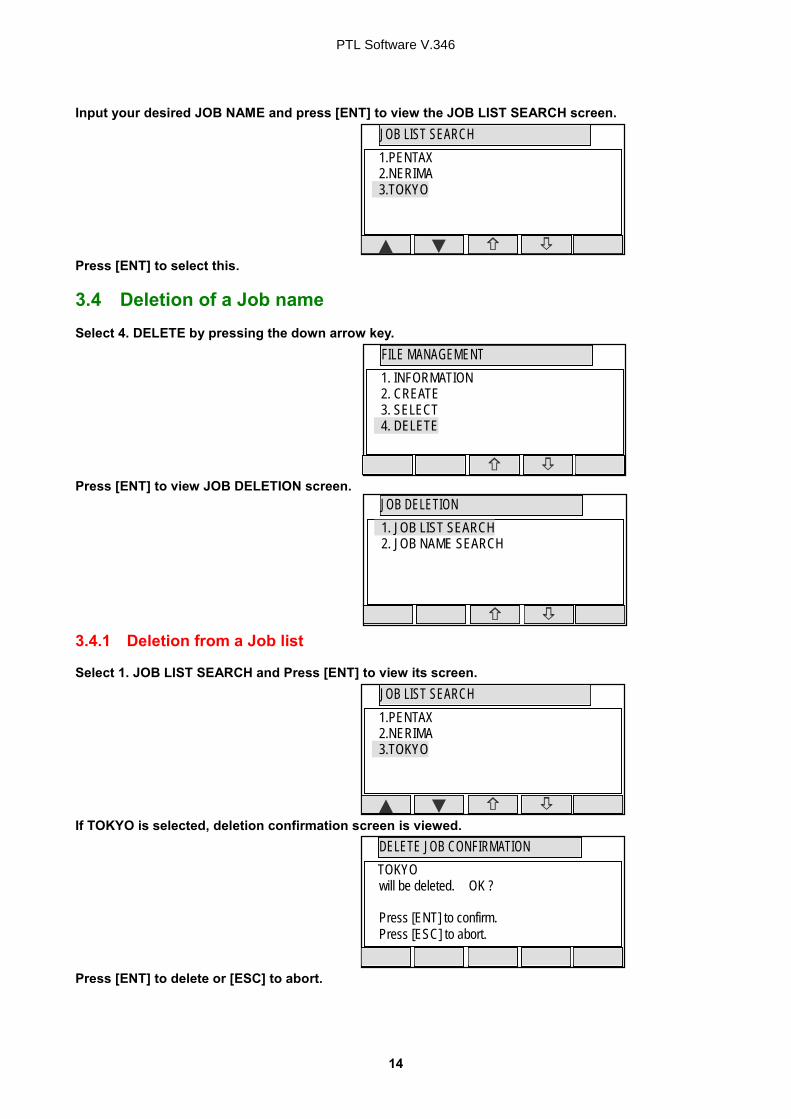
Input your desired JOB NAME and press [ENT] to view the JOB LIST SEARCH screen. Press [ENT] to select this. 3.4 Deletion of a Job name Select 4. DELETE by pressing the down arrow key. Press [ENT] to view JOB DELETION screen. 3.4.1 Deletion from a Job list Select 1. JOB LIST SEARCH and Press [ENT] to view its screen. If TOKYO is selected, deletion confirmation screen is viewed. Press [ENT] to delete or [ESC] to abort.
JOB LIST SEARCH
1.PENTAX 2.NERIMA 3.TOKYO
FILE MANAGEMENT
1. INFORMATION 2. CREATE 3. SELECT 4. DELETE
JOB LIST SEARCH
1.PENTAX 2.NERIMA 3.TOKYO
JOB DELETION 1. JOB LIST SEARCH 2. JOB NAME SEARCH
DELETE JOB CONFIRMATION TOKYO will be deleted. OK ? Press [ENT] to confirm. Press [ESC] to abort.
PTL Software V.346
15
3.4.2 Deletion from a Job name search Select 2. JOB NAME SEARCH by pressing the down arrow key. Press [ENT] to view the JOB NAME INPUT screen. Input your desired JOB NAME to delete and press [ENT] to view the DELETE JOB CONFIRMATION screen. Press [ENT] to delete or [ESC] to abort. The RRRR-300 series instrument has a Job name of the “PENTAX” as its default setting. Therefore, each data is stored in “PENTAX” unless another new Job name is created. When another Job name is created, each data is stored in the new Job name.
JOB DELETION
1. JOB LIST SEARCH 2. JOB NAME SEARCH
JOB NAME INPUT
CLEAR TO 123 BS
1.JOB LIST SEARCH 2.JOB NAME SEARCH TOKYO
DELETE JOB CONFIRMATION TOKYO will be deleted. OK ? Press [ENT] to confirm. Press [ESC] to abort.
PTL Software V.346
16
4. MEASURE An operator can measure the Foresight point Coordinates from the “Station point Coordinates and Backsight Coordinates” or the “Station point Coordinates and Azimuth”, and can store the Point name and measured Coordinates in the memory. When the Coordinates of the Station point and Backsight point are already stored in the memory, the new Coordinates input can be omitted by calling or searching from the point name LIST. The point name is within 15 characters and the Coordinates are within 8 in integer and 3 in decimal number. There are two Coordinates types of Rectangular and Polar Coordinates in this [MEASURE]. The Offset at the Target point is possible and the Remote measurement by aiming at any point is possible as well when you select the Rectangular Coordinates.
An operator can perform the [MEASURE] function only when the Telescope is at the “ Face left position”. Select the Target type before performing the [MEASURE]. After measuring rectangular coordinates by [MEASURE] function of PowerTopoLite, it is possible to display Angle and Distance by switching the [F3] key. When Remote mode is selected, Angle and Distance are also calculated according to the coordinates of the aiming point on real time. When Offset mode is selected, Angle and Distance are also calculated according to the coordinates where offset value is added.
Backsight P. Coordinates
Azimuth
Reference P.
1.Cylinder
2.Fixed plane
3.Rotated
Station Point
Offset
Remote
PTL Software V.346
17
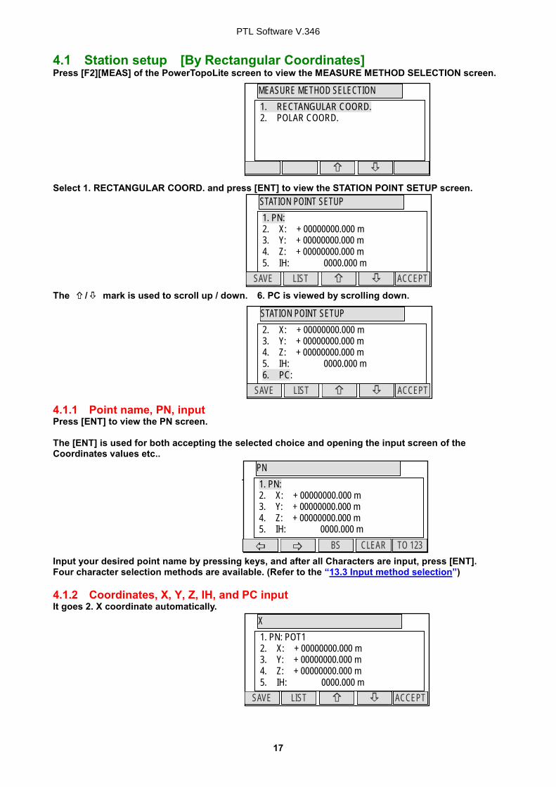
4.1 Station setup [By Rectangular Coordinates] Press [F2][MEAS] of the PowerTopoLite screen to view the MEASURE METHOD SELECTION screen. Select 1. RECTANGULAR COORD. and press [ENT] to view the STATION POINT SETUP screen. The / mark is used to scroll up / down. 6. PC is viewed by scrolling down. 4.1.1 Point name, PN, input Press [ENT] to view the PN screen. The [ENT] is used for both accepting the selected choice and opening the input screen of the Coordinates values etc.. Input your desired point name by pressing keys, and after all Characters are input, press [ENT]. Four character selection methods are available. (Refer to the “13.3 Input method selection”) 4.1.2 Coordinates, X, Y, Z, IH, and PC input It goes 2. X coordinate automatically.
POT1 PN
1. PN: 2. X: + 00000000.000 m 3. Y: + 00000000.000 m 4. Z: + 00000000.000 m 5. IH: 0000.000 m
STATION POINT SETUP 1. PN: 2. X: + 00000000.000 m 3. Y: + 00000000.000 m 4. Z: + 00000000.000 m 5. IH: 0000.000 m
ACCEPT LIST SAVE
STATION POINT SETUP 2. X: + 00000000.000 m 3. Y: + 00000000.000 m 4. Z: + 00000000.000 m 5. IH: 0000.000 m 6. PC:
ACCEPT LIST SAVE
X 1. PN: POT1 2. X: + 00000000.000 m 3. Y: + 00000000.000 m 4. Z: + 00000000.000 m 5. IH: 0000.000 m
ACCEPT LIST SAVE
PTL Software V.346
18
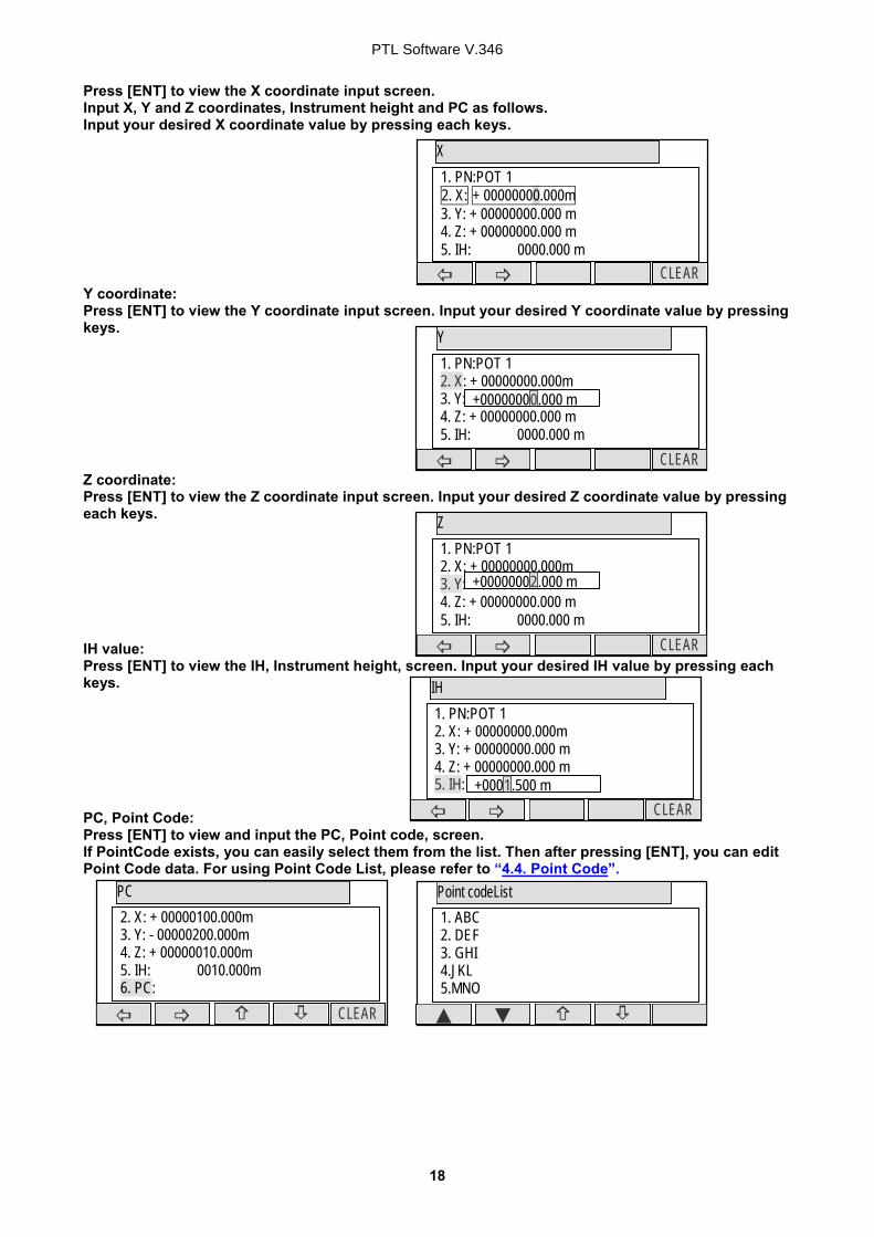
Press [ENT] to view the X coordinate input screen. Input X, Y and Z coordinates, Instrument height and PC as follows. Input your desired X coordinate value by pressing each keys. Y coordinate: Press [ENT] to view the Y coordinate input screen. Input your desired Y coordinate value by pressing keys. Z coordinate: Press [ENT] to view the Z coordinate input screen. Input your desired Z coordinate value by pressing each keys. IH value: Press [ENT] to view the IH, Instrument height, screen. Input your desired IH value by pressing each keys. PC, Point Code: Press [ENT] to view and input the PC, Point code, screen. If PointCode exists, you can easily select them from the list. Then after pressing [ENT], you can edit Point Code data. For using Point Code List, please refer to “4.4. Point Code”.
1. PN:POT 1 2. X: + 00000000.000m 3. Y: + 00000000.000 m 4. Z: + 00000000.000 m 5. IH: 0000.000 m
IH
CLEAR
1. PN:POT 1 2. X: + 00000000.000m 3. Y: + 00000000.000 m 4. Z: + 00000000.000 m 5. IH: 0000.000 m +0001.500 m
Z
CLEAR
1. PN:POT 1 2. X: + 00000000.000m 3. Y: + 00000000.000 m 4. Z: + 00000000.000 m 5. IH: 0000.000 m
+00000002.000 m
Y
CLEAR
1. PN:POT 1 2. X: + 00000000.000m 3. Y: + 00000000.000 m 4. Z: + 00000000.000 m 5. IH: 0000.000 m
+00000000.000 m
PTL Software V.346
19
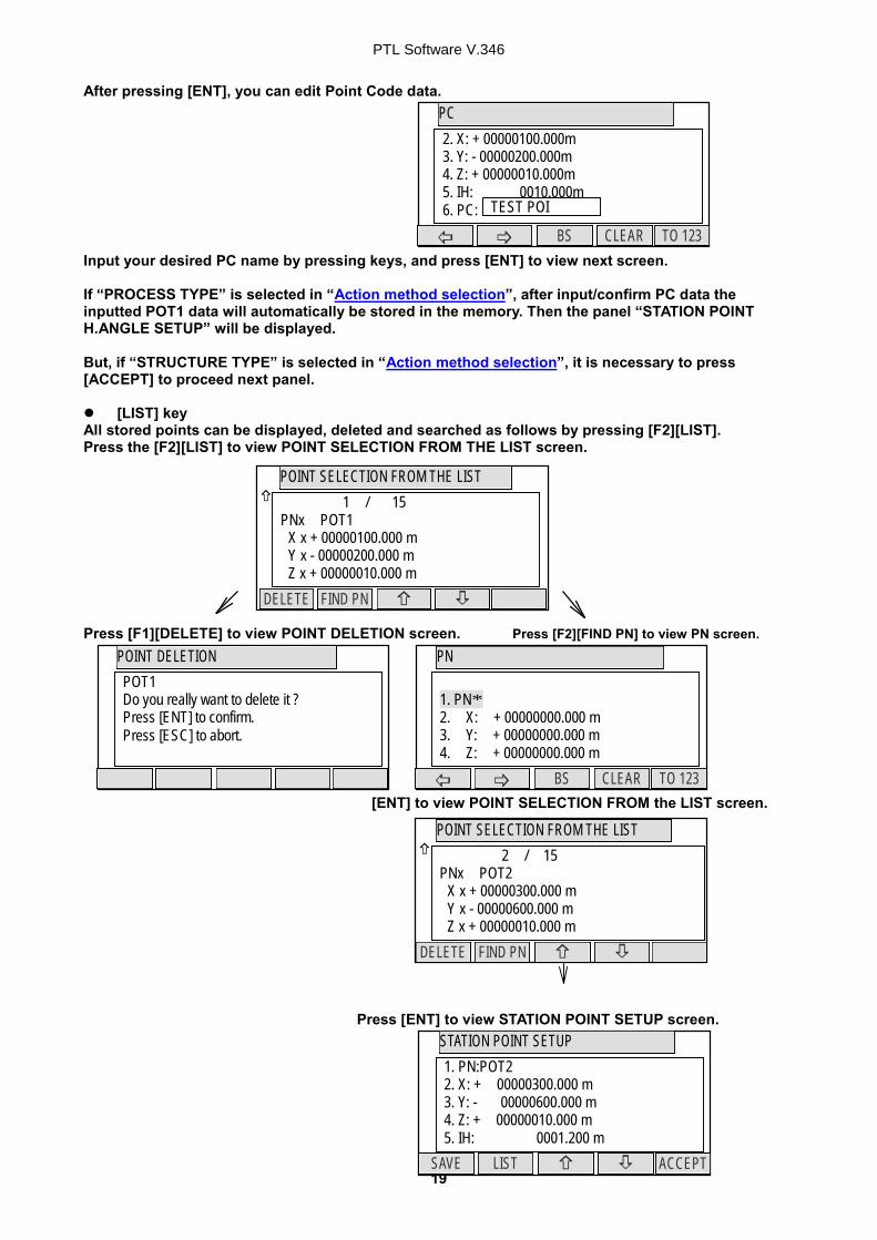
After pressing [ENT], you can edit Point Code data. Input your desired PC name by pressing keys, and press [ENT] to view next screen. If “PROCESS TYPE” is selected in “Action method selection”, after input/confirm PC data the inputted POT1 data will automatically be stored in the memory. Then the panel “STATION POINT H.ANGLE SETUP” will be displayed. But, if “STRUCTURE TYPE” is selected in “Action method selection”, it is necessary to press [ACCEPT] to proceed next panel. [LIST] key
All stored points can be displayed, deleted and searched as follows by pressing [F2][LIST]. Press the [F2][LIST] to view POINT SELECTION FROM THE LIST screen. Press [F1][DELETE] to view POINT DELETION screen. Press [F2][FIND PN] to view PN screen.
[ENT] to view POINT SELECTION FROM the LIST screen.
Press [ENT] to view STATION POINT SETUP screen.
POINT SELECTION FROM THE LIST
FIND PN DELETE
1 / 15 PNx POT1 X x + 00000100.000 m Y x - 00000200.000 m Z x + 00000010.000 m
POINT DELETION
POT1 Do you really want to delete it ? Press [ENT] to confirm. Press [ESC] to abort.
POINT SELECTION FROM THE LIST
FIND PN DELETE
2 / 15 PNx POT2 X x + 00000300.000 m Y x - 00000600.000 m Z x + 00000010.000 m
�
STATION POINT SETUP
ACCEPT LIST SAVE
1. PN:POT2 2. X: + 00000300.000 m 3. Y: - 00000600.000 m 4. Z: + 00000010.000 m 5. IH: 0001.200 m
PC
CLEAR TO 123 BS
2. X: + 00000100.000m 3. Y: - 00000200.000m 4. Z: + 00000010.000m 5. IH: 0010.000m 6. PC: TEST POI
POT1 PN
1. PN* 2. X: + 00000000.000 m 3. Y: + 00000000.000 m 4. Z: + 00000000.000 m
CLEAR TO 123 BS
PTL Software V.346
20
PTL Software V.346
21
4.2 Station Orientation Press the [F1][ACCEPT] to view the STATION POINT H. ANGLE SETUP screen. Please, note that the rotation of the “H.angle” depend on the rotation setting of “Coordinate axis definition”. 4.2.1 Station orientation Input the H. angle by pressing [F2][INPUT], [F3][0SET] and [F4] [HOLD] or Reference point Coordinates by pressing [F5][BSP]. Pressing [F2][INPUT] Pressing [F5][BSP] Press [ENT] to view the input window. Press [ENT] after entering the Horizontal angle. The AIM AT THE REFERENCE POINT screen is viewed when “1. ON” of “7.REQUEST AIMING” of “Preference” is selected and not viewed when “2. OFF” is selected. In case of that BSP Coordinates are inputted, this message is always viewed on the screen. Coordinates display and Angle & Distance display Press the [ENT] at the STATION POINT H. ANGLE SETUP screen to view the MEASURE screen. Press the [MEAS] to measure the Distance and display the Coordinates. 1) Press [F5][PAGE] twice to view [F3][ANG & DIST]. 2) Press [F3][ANG & DIST] to view [F3][COORD.] and Angle and Distance values. 3) Press [F3][COORD.] to view [F3][ANG&DIST] and Coordinates.
H. angle XXX° XX’ XX”
BSP SETUP
ACCET LIST SAVE
1. PN: 2. X: + 00000100.000 m 3. Y: + 00000310.000 m 4. Z: + 00000110.000 m 5.PC
AIM AT THE REFERENCE POINT.
ENT ESC
Aim at the reference point Press [ENT] when ready.
STATION POINT H. ANGLE SETUP
HOLD BSP INPUT 0 SET
H. angle XXX° XX’ XX”
H ANGLE
CLEAR
STATION POINT H. ANGLE SETUP
HOLD BPS INPUT 0 SET
H. angle xxx° xx’ xx”
MEASURE
EDIT PAGE SAVE ME/SAVE MEAS
PN PH X.XXX m X Y Z
ANG. & DIST.
DISP COORD
PN PH X.XXX m H.angle XXX° XX’ XX” V.angle YY° YY’ YY” H.dst X.XXX m
MEASURE
PAGE TARGET ANG&DIST EDM
PN PH X.XXX m X + X.XXX m Y + X.XXX m Z + X.XXX m
PTL Software V.346
22
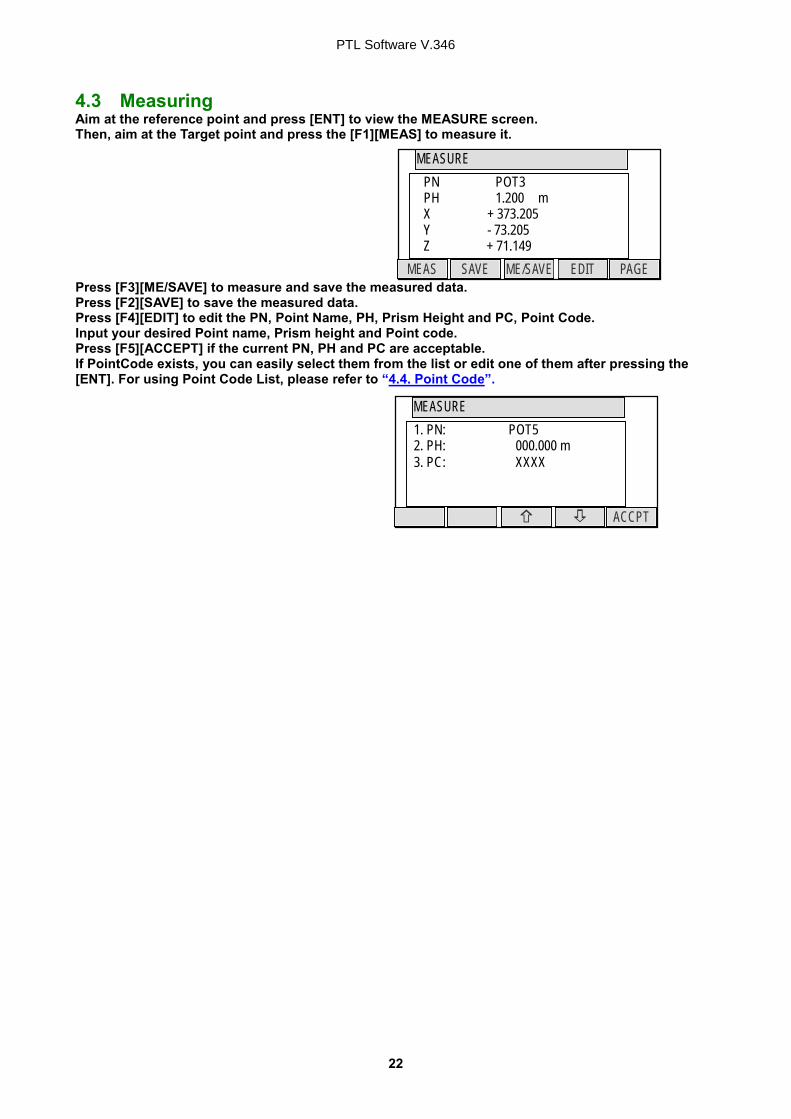
4.3 Measuring Aim at the reference point and press [ENT] to view the MEASURE screen. Then, aim at the Target point and press the [F1][MEAS] to measure it. Press [F3][ME/SAVE] to measure and save the measured data. Press [F2][SAVE] to save the measured data. Press [F4][EDIT] to edit the PN, Point Name, PH, Prism Height and PC, Point Code. Input your desired Point name, Prism height and Point code. Press [F5][ACCEPT] if the current PN, PH and PC are acceptable. If PointCode exists, you can easily select them from the list or edit one of them after pressing the [ENT]. For using Point Code List, please refer to “4.4. Point Code”.
MEASURE
EDIT PAGE SAVE ME/SAVE MEAS
PN POT3 PH 1.200 m X + 373.205 Y - 73.205 Z + 71.149
MEASURE
ACCPT
1. PN: POT5 2. PH: 000.000 m 3. PC: XXXX
PTL Software V.346
23
4.4 Point Code The PC, PointCodeList can be used for adding your desired attributes to Rect. and Polar data. If point codes are stored under the job named "PointCodeList", you can easily select one of the PointCode from the list or edit one of them after pressing [ENT]. Please, note that Point Code, which is saved in the other job can not be refered as a list. “PointCodeList” can be created by either using “5.2 Create the Rectangular Point” function or Importing “PointCodeList” file. Making “PointCodeList”: Create / select “PointCodeLList” job using “3. FILE MANAGER”. Then input point data according to “5.2 Create the Rectangular Point”. Input any value into “PN” field and leave the X, Y, and Z field “0”. And input PointCode data into “PC” field. Importing “PointCodeList” file: PointCodeList can be used after importing it from external devices (ex. PC ). After importing, it is stored in the internal memory of the instrument. To store user defined ”PointCodeList”, please carry out following procedure. Preparing “PointCodeList” file: Make a “PointCodeList.csv” file with reference to a sample “PointCodeList.csv” file that is contained in the “R-300 Supplement Disk” for the format. Please, note that the newly entered PointCode on the instrument is not added to the PointCodeList that is stored in the memory. In this case, edit “PointCodeList.csv” separately.
Format of the “PointCodeList” file Field 1 Field 2 Field 3 Field 4 Field 5 Field 6 Field 7 Description Record Type No. Name Description Ex. Line 1 1, , PointCodeList, , Job record Job No.:
(N/A) Job Name (Fixed for “PointCodeList”.)
Ex. Line 2 31, , 2, DEF, , , , Coord. data record Point No.:
(N/A) Point Name (Shoul not duplicated and Max. 15 Character.)
Point Code (Max. 15 Character.)
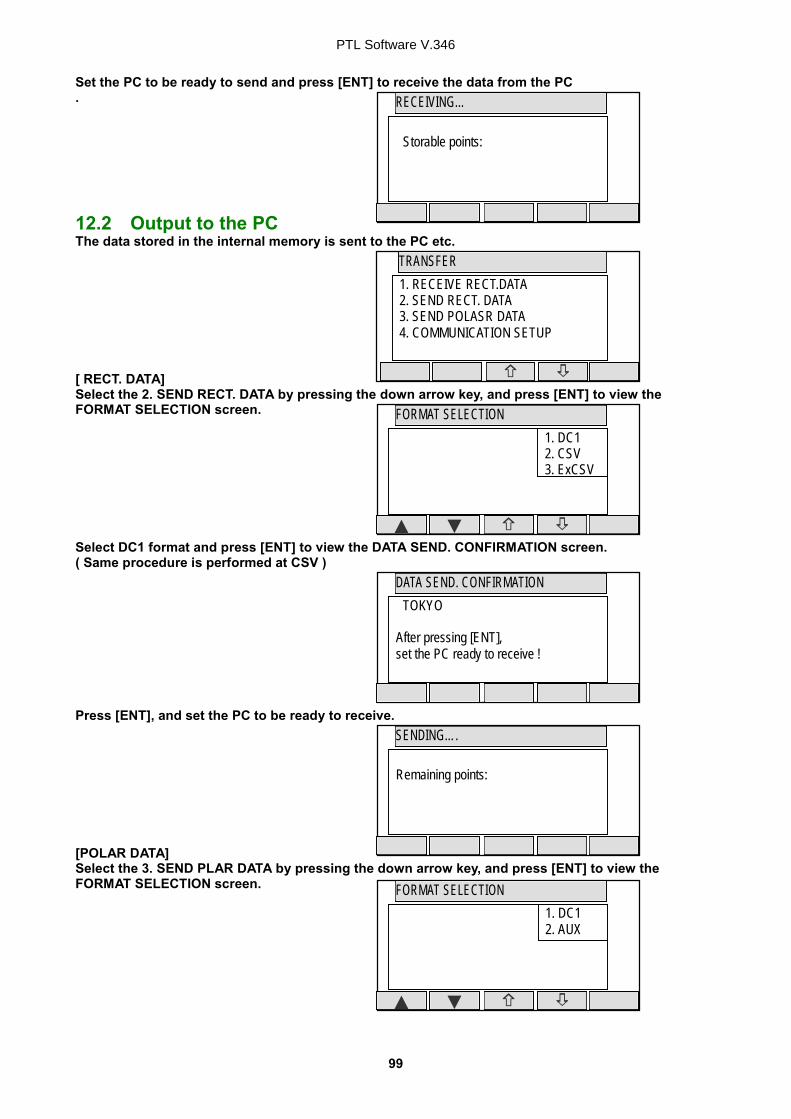
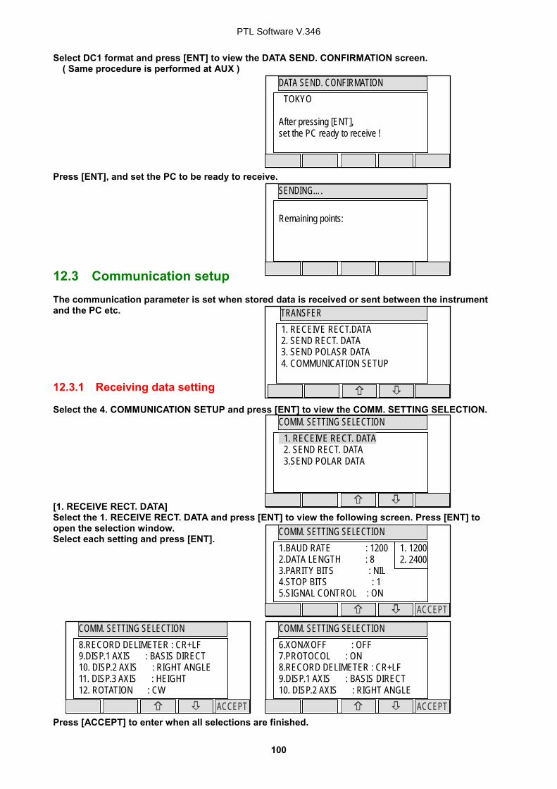
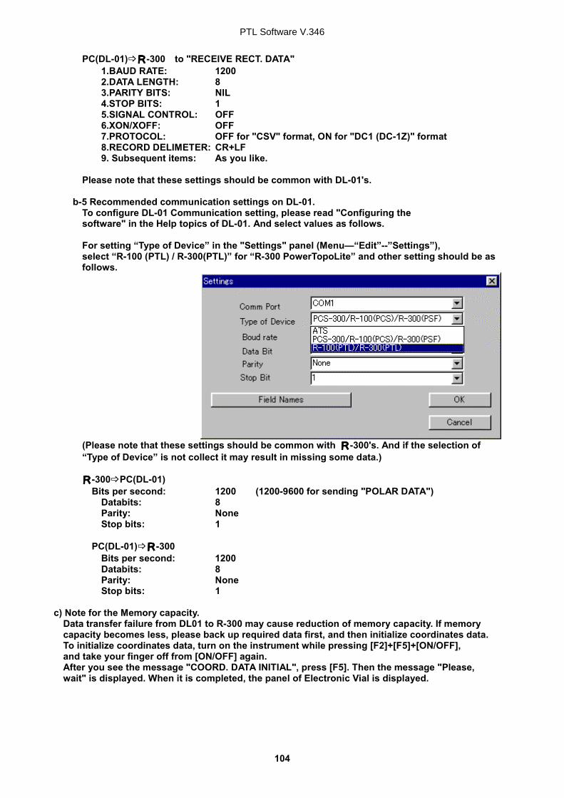
Setting the PROTOCOL: Press the [F3][I/O] of the PowerTopoLite screen to view the TRANSFER screen. To check the communication setting, select the “4. COMMUNICATION SETUP” in the “TRANSFER” screen and press [ENT] to view “COMM. SETTING SELECTION” screen. Then select “1. RECEIVE RECT.DATA” and set
“1. BAUD RATE” to “1200”, “6. XON/XOFF” to “OFF” for using “DL-01”,
“ON” for using “HYPER TERMINAL”. “7. PROTOCOL” to “OFF” “8. RECORD DELIMITER” to “CR+LF” and press [ACCEPT]. ( cf. “12.3.1 Receiving data setting” )
TRANSFER
1. RECEIVE RECT.DATA 2. SEND RECT. DATA 3. SEND POLASR DATA 4. COMMUNICATION SETUP
PTL Software V.346
24
Receive rect. Data: After setting the parameters, select the “1. RECEIVE RECT. DATA” in the “TRANSFER” screen and press [ENT] to view “FORMAT SELECTION” screen. In this screen select “3.ExtCSV” to send PointCodeList.( cf. ”.1 Input from the PC” ) After complete data transfer, number of received points is displayed. Press [ENT]. If the name of job in the PointCodeList file ( ex. “1,,PointCodeList,”) is same as current job and you want to overwrite or append, select “1. OVERWRITE” or ” 2. APPEND”. If the name of job in the PointCodeList file ( ex. “1, PointCodeList,”) is different from current job or if you don’t want overwrite or append when jobs names are same, select “3. SAVE”. Received data will be written into the internal memory of the instrument.
FORMAT SELECTION
1. DC1 2. CSV 3. ExtCSV
RECEVING COMPLETED
XXpoint received !
RECEIVED DATA SAVING METHOD
1. OVERWRITE 2. APPEND 3. SAVE
PTL Software V.346
25
4.5 Remote, Offset, Station, and H. angle function 4.5.1 Remote Press [F5][PAGE] to view another MEASURE menu. Press [F1][REMOTE] once and then quickly press this key again to measure your desired point Coordinates by moving the telescope. The displayed Coordinates automatically change according to your aiming point. The Remote is a function of, so to speak, “Real-time offset”. If a reference point or offset point is measured, the Coordinates of your aiming point are calculated based on the reference plane. There are three calculation methods of Cylindrical face, Fixed plane and Rotated plane. They are selected by the “Preference”. Refer to “Remote method selection”. The calculations are performed on the virtual planes. To quit the Remote measurement, press [F1][REMOTE] twice again.
MEASURE
H .ANGL PAGE OFFSET STATION REMOTE
PN POT3 PH X.XXX m X Y Z
Reference P.
1. Cylinder
2. Fixed
3. Rotated
Station Point
Remote
MEASURE
EDIT PAGE SAVE ME/SAVE MEAS
PN POT3 PH X.XXX m X Y Z
PTL Software V.346
26
Three type menus can be used by pressing [F5][PAGE]. Another is following menu. The target type can be selected by pressing [F2][TARGET]. EDM settings can be selected by pressing [F1][EDM]. For example, change 1.PRIM. MEAS KEY (MEAS) to TRACK SHOT or TRACK CONT if you want to use tracking measurement with primary MEAS key (MEAS). Coordinates display and Angle & Distance display 1) Press [F5][PAGE] twice to view [F3][ANG & DIST]. 2) Press [F3][ANG & DIST] to view [F3][COORD.] and Angle and Distance values. 3) Press [F3][COORD.] to view [F3][ANG&DIST] and Coordinates. 4.5.2 Offset Press the [F2][OFFSET] to view the OFFSETS screen. Offset enables you to work with Offsets. The following offsets are available. Press [ENT] to view the offset input window. Input the RO offset value by pressing keys. VO, DO and TO values are inputted in the same manner.
MEASURE
PAGE TARGET EDM
PN POT3 PH X.XXX m X Y Z
EDM SETTINGS
ACCEPT
1. PRIM. MEAS KEY : MEAS. SHOT 2. SEC. MEAS KEY : TRACK CONT 3. TRACK MIN DISP. : COARSE 4. SHOT COUNT : 1 TIME 5. SHOT INPUT : 01 TIMES
MEASURE
PAGE TARGET ANG&DIST EDM
PN PH X.XXX m X + X.XXX m Y + X.XXX m Z + X.XXX m
ANG.& DISP.
DISP COORD
PN PH X.XXX m H.angle XXX° XX’ XX” V.angle YY° YY’ YY” H.dst X.XXX m
OFFSETS
ACCEPT
1. RO: 0000.000 m 2. VO: 0000.000 m 3. DO: 0000.000 m 4. TO: 0000.000 m
RO
CLEAR
1. RO: 2. VO: +0000.000 m 3. DO: +0000.000 m 4. TO: +0000.000 m
+0000.000m
PTL Software V.346
27
After input “TO” value, press [ENT] to view the MEASURE screen. (Or press [ESC] then press [ACCEPT].) The offset values are added to X,Y and Z values. The input value of offset is cleared when you save the surveying point and step forward to the next surveying point. RO: Radial Offset (RO: On the horizontal plane. Offset P: Along the line of measurement, thus along the slope ) Offset P: Offset Point VO: Vertical Offset ( Along the third axis ) DO: Distance Offset ( Along the line of measurement, thus along the slope ) TO: Tangential offset ( TO: On the horizontal plane, perpendicular to the horizontal line between Station and Point. Offset P: Along the slope)
SP
Y
Z
VO
SP X,Y
Offset P
P
X
TO
SP Offset P
P
Z
ROSP X,Y
P Offset P
Z DO
X,Y
Offset P
P
OFFSET
H ANGLE PAGE OFFSET STATION REMOTE
PN POT3 PH m X + offset…… Y + offset…… Z + offset……
PTL Software V.346
28
Coordinates display and Angle & Distance display 1) Press [F5][PAGE] twice to view [F3][ANG & DIST]. 2) Press [F3][ANG & DIST] to view [F3][COORD.] and Angle and Distance values. 3) Press [F3][COORD.] to view [F3][ANG&DIST] and Coordinates. 4.5.3 Station Press [F3][STATION] to return to STATION POINT SETUP screen. 4.5.4 H. angle Press [F4][H.ANGLE] to return to STATION POINT H. ANGLE SETUP screen. Press [ENT] to view the MEASURE screen.
�STATION POINT SETUP
ACCEPT LIST SAVE
1. PN: 2. X: + 00000000.000 m 3. Y: + 00000000.000 m 4. Z: + 00000000.000 m 5. IH: 0000.0 m
STATION POINT H. ANGLE SETUP
HOLD INVERS INPUT 0 SET
H. angle xxx° xx’ xx”
MEASURE
PAGE TARGET ANG&DIST EDM
PN PH X.XXX m X + X.XXX m Y + X.XXX m Z + X.XXX m
ANG.& DISP.
DISP COORD
PN PH X.XXX m H.angle XXX° XX’ XX” V.angle YY° YY’ YY” H.dst X.XXX m
PTL Software V.346
29
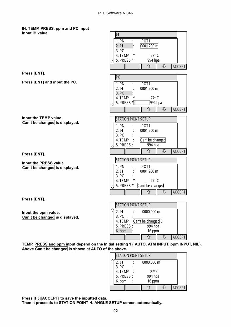
4.6 Station setup [ By Polar Coordinates] The same Point Name of the plural polar points can be saved. Press [F2][MEAS] of the PowerTopoLite screen to view the MEASURE METHOD SELECTION screen. Select 2. POLAR COORD. and press [ENT] to view the STATION POINT SETUP screen. The / mark is used to scroll up / down. 6. PC is viewed by . 4.6.1 Point name, PN, input Press [ENT] to view the PN screen. 4.6.2 IH, TEMP, PRESS, ppm and PC input Input IH value. Press [ENT]. Input the PC. Press [ENT] to view and input the PC, Point code, screen. If PointCode exists, you can easily select them from the list or edit one of them after pressing the [ENT]. For using Point Code List, please refer to “4.4. Point Code”.
STATION POINT SETUP
ACCEPT SAVE
1. PN : 2. IH : 0000.000 m 3. PC : 4. TEMP * 27° C 5. PRESS * 994 hpa
STATION POINT SETUP
ACCEPT SAVE
2. IH : 0000.000 m 3. PC : 4. TEMP * 27° C 5. PRESS * 994 hpa 6. ppm *
MEASURE METHOD SELECTION
1. RECTANGULAR COORD. 2. POLAR COORD.
PN 1. PN : 2. IH : 0000.000 m 3. PC : 4. TEMP * 27° C 5. PRESS * 994 hpa
POT1
CLEAR TO 123 BS
IH 1. PN : 2. IH : 0000.000 m 3. PC : 4. TEMP * 27° C 5. PRESS * 994 hpa
CLEAR TO 123 BS
PTL Software V.346
30
If “PROCESS TYPE” is selected in “Action method selection”, the inputted point data will be stored in the memory with [SAVE]. Then the panel “STATION POINT H.ANGLE SETUP” will be displayed without pressing [ACCEPT]. But, if “STRUCTURE TYPE” is selected in “Action method selection”, it is necessary to press [ACCEPT] to proceed next panel. Input the TEMP value. Can’t be changed is displayed. Press [ENT]. Input the PRESS value. Can’t be changed is displayed. Press [ENT]. Input ppm value. Can’t be changed is displayed. TEMP, PRESS and ppm input depend on the “Initial setting 1” ( AUTO, ATM INPUT, ppm INPUT, NIL). Above Can’t be changed is shown at AUTO of the above.
STATION POINT SETUP
ACCEPT SAVE
1. PN : XXXXX 2. IH : 000X.X00 m 3. PC : 4. TEMP * Can’ be changed 5. PRESS * 994 hpa
STATION POINT SETUP
ACCEPT SAVE
1. PN : XXXXX 2. IH : 000X.X00 m 3. PC : 4. TEMP * 27 C 5. PRESS * Can’ be changed
STATION POINT SETUP
ACCEPT SAVE
2. IH : 000X.X00 m 3. PC : 4. TEMP * 27 C 5. PRESS * 994 hpa 6. ppm * Can’t be changed
PC 1. PN : 2. IH : 0000.000 m 3. PC : 4. TEMP * 27° C 5. PRESS * 994 hpa
CLEAR TO 123 BS
PTL Software V.346
31
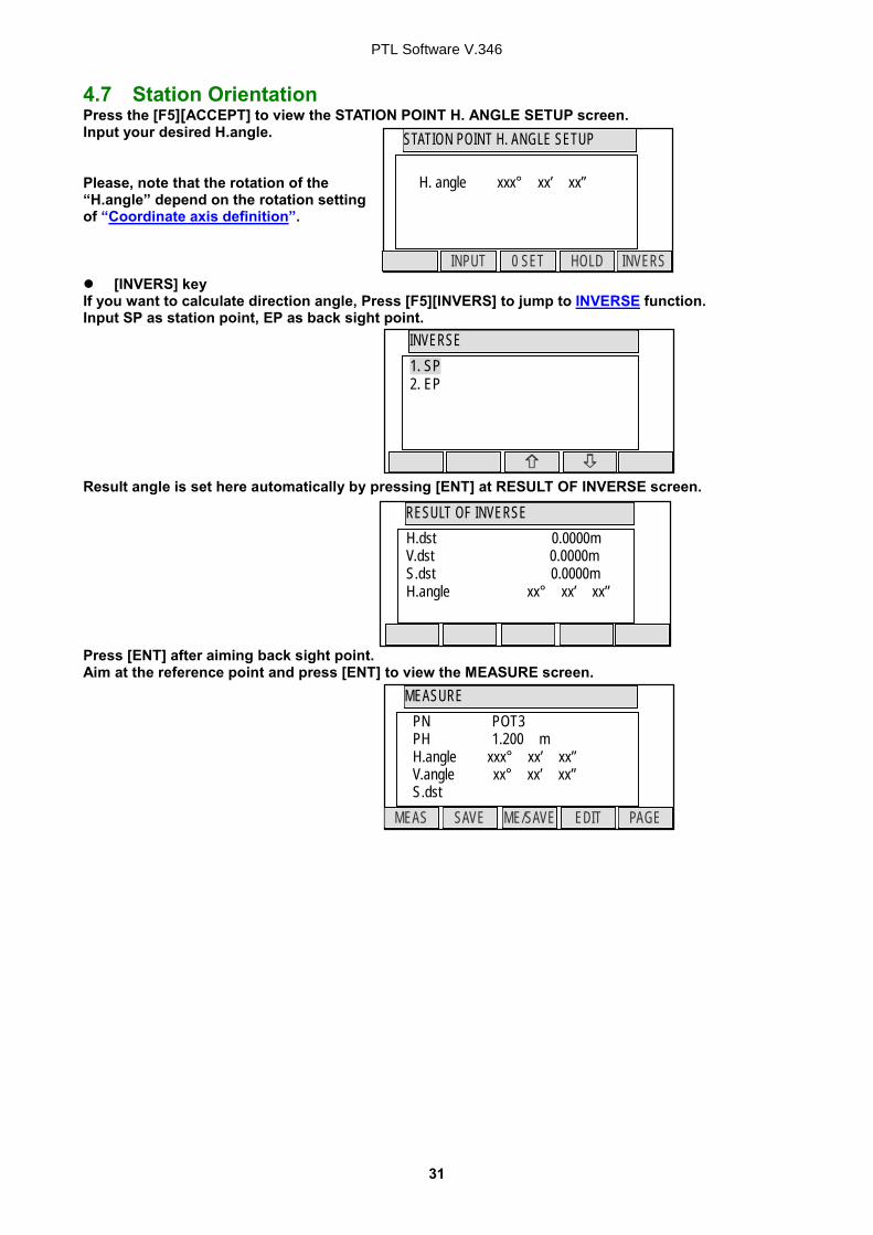
4.7 Station Orientation Press the [F5][ACCEPT] to view the STATION POINT H. ANGLE SETUP screen. Input your desired H.angle. Please, note that the rotation of the “H.angle” depend on the rotation setting of “Coordinate axis definition”. [INVERS] key
If you want to calculate direction angle, Press [F5][INVERS] to jump to INVERSE function. Input SP as station point, EP as back sight point. Result angle is set here automatically by pressing [ENT] at RESULT OF INVERSE screen. Press [ENT] after aiming back sight point. Aim at the reference point and press [ENT] to view the MEASURE screen.
4.8 Measuring Then, aim at the Target point and press the [F1][MEAS] to measure the distance. Press [F3][ME/SAVE] to measure and save the measured data. Press [F2][SAVE] to save the measured data. Press [F4][EDIT] to edit the PN, Point Name, PH, Prism Height and PC, Point Code. Press [ENT] to view each input window by pressing up or down arrow key, and input your desired point name or prism height or point code. Press [F5][ACCEPT] if the current PN, PH and PC are acceptable. PC, Point Code: Press [ENT] to view and input the PC, Point code, screen. If PointCode exists, you can easily select them from the list or edit one of them after pressing the [ENT]. For using Point Code List, please refer to “4.4. Point Code”. Press [F5][PAGE] to view another menu. Station point setup can be changed by pressing [F3][STATION].
MEASURE
ACCEPT
1. PN: POT5 2. PH: 000.000 m 3. PC:
MEASURE
EDIT PAGE SAVE ME/SAVE MEAS
PN POT3 PH 1.200 m H.angle xxx° xx’ xx” V.angle xxx° xx’ xx” S.dst xx.xxx m
MEASURE
PAGE OFFSET STATION
PN POT3 PH 1.200 m H.angle xxx° xx’ xx” V.angle xxx° xx’ xx” S.dst xx.xxx m
MEASURE
PAGE TARGET EDM
PN POT3 PH 1.200 m H.angle xxx° xx’ xx” V.angle xxx° xx’ xx” S.dst xx.xxx m
�
STATION POINT SETUP
ACCEPT SAVE
1. PN : 2. IH : 0000.000 m 3. PC : 4. TEMP * 27° C 5. PRESS * 994 hpa
PTL Software V.346
33
EDM settings can be selected by pressing [F1][EDM] For example, change 1.PRIM. MEAS KEY (MEAS) to TRACK SHOT or TRACK CONT if you want to use tracking measurement with primary MEAS key (MEAS).
EDM SETTINGS 1. PRIM. MEAS KEY : MEAS. SHOT 2. SEC. MEAS KEY : TRACK CONT 3. TRACK MIN DISP. : COARSE 4. SHOT COUNT : 1 TIME 5. SHOT INPUT : 01 TIMES
ACCEPT
PTL Software V.346
34
4.9 Offset RO: Radial Offset (RO: On the horizontal plane. Offset P: Along the line of measurement, thus along the slope ) Offset P: Offset Point DO: Distance Offset ( Along the line of measurement, thus along the slope ) Press the [F2][OFFSET] to view the OFFSET screen. Offset enables you to work with Offset. The following offset are available. Press [ENT] to view the offset input window. Input the RO offset value by pressing each keys. DO values are inputted in the same manner. Press [ENT] and then [ACCEPT] to view the MEASURE screen. The S.dst (slope distance) is adjusted by inputted offset value. The input value of offset is cleared when you save the surveying point and step forward to the next surveying point.
OFFSETS
ACCEPT
1. RO: +0000.000 m 2. DO: +0000.000 m
0000.000m
RO
CLEAR
1. RO: +0000.000 m 2. DO: +0000.000 m
SP
Z
ROSP X,Y
P Offset P
Z DO
X,Y
Offset P
P
OFFSET
PAGE OFFSET STATION
PN POT3 PH 1.200 m H.angle xxx° xx’ xx” V.angle xxx° xx’ xx” S.dst OFFSET…… m
PTL Software V.346
35
5. VIEW AND EDIT
Stored data are displayed graphically, and the edit of the stored data is possible by this Function.
The Z Coordinate (the height) of the point is ignored in the graphical display of the point data. Four menu items are available: Graphical view CREATE THE RECT. POINT EDIT THE RECT. DATA EDIT THE POLAR DATA
5.1 Graphical View From the PowerTopoLite screen, press [F3][VIEW] to view its screen. Press [ENT] to view the GRAPHICAL VIEW screen. Points, Point names and their Graphics are displayed. The graphic is moved by pressing the arrow keys. The Graphics are not displayed when points are not stored. Two or more points are needed. Press the [F5][PAGE] to view another menu. [DISP]: Each Graphic is displayed as following order by pressing this key. Points Points + Line Points + Points names Full [ZOOM ALL]: Return to the ordinary Graphics size [ZOOM IN]: Enlarge the Graphics size. [ZOOM OUT]: Reduce the Graphics size.
VIEW & EDIT
1. GRAPHICAL VIEW 2. CREATE THE RECT. POINT 3. EDIT THE RECT. DATA 4. EDIT THE POLAR DATA
07AA 005BB
ZOOM PAGE ZOOM ZOOM IN DISP
07AA 005BB
PAGE
PTL Software V.346
36
RECT. DATA EDIT
LIST SAVE
1. PN: 2. X : + 00000000.000 m 3. Y : + 00000000.000 m 4. Z : + 00000000.000 m 5. PC:
RECT. DATA EDIT
LIST SAVE
1. PN: XXXXX 2. X : + 000000XX.000 m 3. Y : + 000000XX.000 m 4. Z : + 000000XX.000 m 5. PC: XXXX
RECT. DATA EDIT
FIND PN DELETE
4 / 15 PN x XXXXX X x+ 000000XX.000 m Y x+ 000000XX.000 m Z x + 000000XX.000 m
5.2 Create the Rectangular Point Select 2. CREATE THE RECT. POINT and press [ENT] to view the RECT. DATA EDIT screen. Input the PN, X, Y, Z and PC. Press [ENT] to save them. Press [F2][LIST] to view the saved points. The first line of the screen shows now displayed point and the total number of points. Press [F1][DELETE] to delete your desired point. Press [F2][FIND PN] to find your desired point by the PN input.
VIEW & EDIT
1. GRAPHICAL VIEW 2. CREATE THE RECT. POINT 3. EDIT THE RECT. DATA 4. EDIT THE POLAR DATA
PTL Software V.346
37
VIEW & EDIT
1. GRAPHICAL VIEW 2. CREATE THE RECT. POINT 3. EDIT THE RECT. DATA 4. EDIT THE POLAR DATA
RECT. DATA EDIT
FIND PN DELETE
4 / 15 PN x XXXXX X x+ 000000XX.000 m Y x+ 000000XX.000 m Z x + 000000XX.000 m
RECT. DATA EDIT
LIST SAVE
1. PN: XXXXX 2. X : + 000000XX.000 m 3. Y : + 000000XX.000 m 4. Z : + 000000XX.000 m 5. PC: XXXX
POLAR DATA EDIT
FIND PN DELETE
4 / 15 PN x XXXXX TEMP x+ 000000XX.000 m PRESS x+ 000000XX.000 m ppm x + 000000XX.000 m
POLAR DATA EDIT
LIST SAVE
1.PN : XXXX 2.IH : XXXX.XXX m 3.TEMP x+ 000000XX.000 m 4.PRESS x+ 000000XX.000 m 5.ppm x + 000000XX.000 m
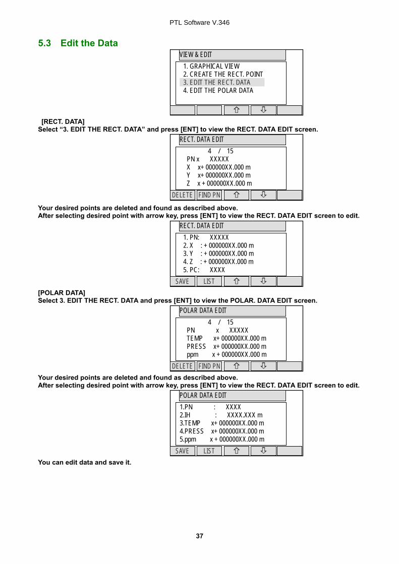
5.3 Edit the Data [RECT. DATA] Select “3. EDIT THE RECT. DATA” and press [ENT] to view the RECT. DATA EDIT screen. Your desired points are deleted and found as described above. After selecting desired point with arrow key, press [ENT] to view the RECT. DATA EDIT screen to edit. [POLAR DATA] Select 3. EDIT THE RECT. DATA and press [ENT] to view the POLAR. DATA EDIT screen. Your desired points are deleted and found as described above. After selecting desired point with arrow key, press [ENT] to view the RECT. DATA EDIT screen to edit. You can edit data and save it.
PTL Software V.346
38
KNOWN POINT COORD. SETUP
ACCEPT LIST SAVE
1.PN : 2. X: + 00000000.000 m 3. Y: + 00000000.000 m 4. Z: + 00000000.000 m 5. PH: 0000.000 m
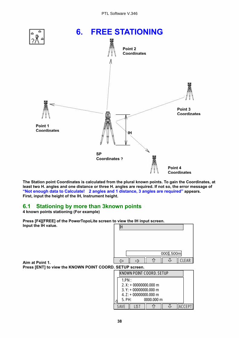
6. FREE STATIONING The Station point Coordinates is calculated from the plural known points. To gain the Coordinates, at least two H. angles and one distance or three H. angles are required. If not so, the error message of “Not enough data to Calculate! 2 angles and 1 distance, 3 angles are required” appears. First, input the height of the IH, Instrument height. 6.1 Stationing by more than 3known points 4 known points stationing (For example) Press [F4][FREE] of the PowerTopoLite screen to view the IH input screen. Input the IH value. Aim at Point 1. Press [ENT] to view the KNOWN POINT COORD. SETUP screen.
IH
CLEAR 0001.500m
SP Coordinates ?
Point 1 Coordinates
Point 3 Coordinates
IH
Point 4 Coordinates
Point 2 Coordinates
PTL Software V.346
39
MEASURE
EDIT DISP TARGET MEAS
1 PN1 PH H.angle V.angle H.dst
ADD/CALC. SELECTION MENU
CALC ADD
Do you want to add more points ? Press [ADD] to add more point. Press [CAL] to calculate.
ADD/CALC. SELECTION MENU
CALC ADD
Do you want to add more points ? Press [ADD] to add more point. Press [CAL] to calculate.
KNOWN POINT COORD. SETUP
ACCEPT LIST SAVE
1.PN : PN2 2. X: + 00000000.000 m 3. Y: + 00000000.000 m 4. Z: + 00000000.000 m 5. PH: 0000.000 m
KNOWN POINT COORD. SETUP
ACCEPT LIST SAVE
1.PN : PN3 2. X: + 00000000.000 m 3. Y: + 00000000.000 m 4. Z: + 00000000.000 m 5. PH: 0000.000 m
KNOWN POINT COORD. SETUP
ACCEPT LIST SAVE
1.PN : PN4 2. X: + 00000000.000 m 3. Y: + 00000000.000 m 4. Z: + 00000000.000 m 5. PH: 0000.000 m
Press [ENT] to open the PN, X, Y, Z, IH and PC input window and input each. Then, press [ENT] and [ACCEPT] to view the MEASURE screen. Press [ENT] to view the ADD/CALC. SELECTION MENU screen. (Measuring is not needed. Just press [ENT].) Press the [F1][ADD] to view the KNOWN POINT COORD. SETUP screen. Aim at Point 2, 3 and 4. In the same manner, input the values of Point 2,3 and 4. After entering values of PN4, press [ENT] twice to view the MEASURE and ADD/CALC SELECTION MENU. Press the [F5][CALC] to view the RESULT COORD. OF STATIONING screen.
PTL Software V.346
40
RESULT COORD. OF STATIONING
ACCEPT VIEW NEXT
PN HA 0° 00’ 05” X Y Z
DEVIATIONS OF THE POINT
ACCEPT REJECT
PN POT4 d HA 0° 00’ 05” dX + 0.000 m dY + 0.000 m dZ + 0.000 m
KNOWN POINT COORD. SETUP
ACCEPT LIST SAVE
1.PN : 2. X: + 00000000.000 m 3. Y: + 00000000.000 m 4. Z: + 00000000.000 m 5. PH: 0000.000 m
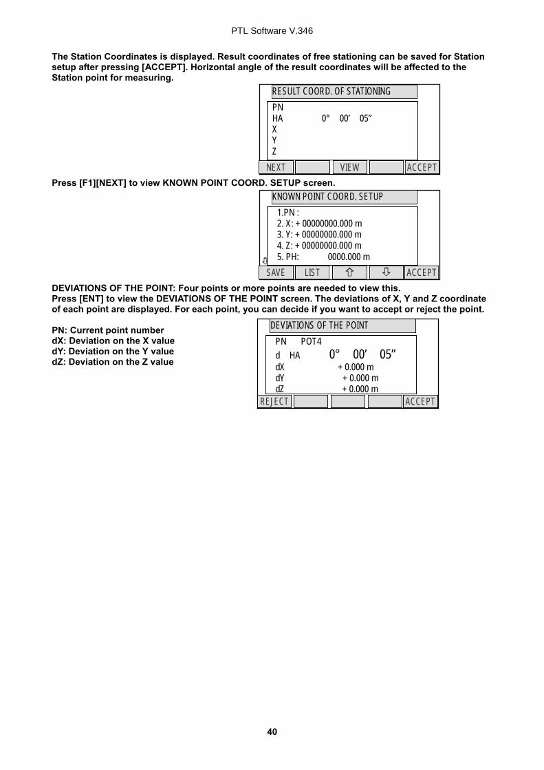
The Station Coordinates is displayed. Result coordinates of free stationing can be saved for Station setup after pressing [ACCEPT]. Horizontal angle of the result coordinates will be affected to the Station point for measuring. Press [F1][NEXT] to view KNOWN POINT COORD. SETUP screen. DEVIATIONS OF THE POINT: Four points or more points are needed to view this. Press [ENT] to view the DEVIATIONS OF THE POINT screen. The deviations of X, Y and Z coordinate of each point are displayed. For each point, you can decide if you want to accept or reject the point. PN: Current point number dX: Deviation on the X value dY: Deviation on the Y value dZ: Deviation on the Z value
PTL Software V.346
41
MEASURE
EDIT DISP TARGET MEAS
1 POT1 PH H.angle V.angle H.dst
ADD/CALC. SELECTION MENU
CALC ADD
Do you want to add more points ? Press [ADD] to add more points. Press [CAL] to calculate.
KNOWN POINT COORD. SETUP
ACCEPT LIST SAVE
1.PN : 2. X: + 00000000.000 m 3. Y: + 00000000.000 m 4. Z: + 00000000.000 m 5. PH: 0000.000 m
�
SET UP THE KNOWN POINT
ACCEPT LIST SAVE
1.PN : 2. X: + 00000000.000 m 3. Y: + 00000000.000 m 4. Z: + 00000000.000 m 5. PH: 0000.000 m
IH
CLEAR
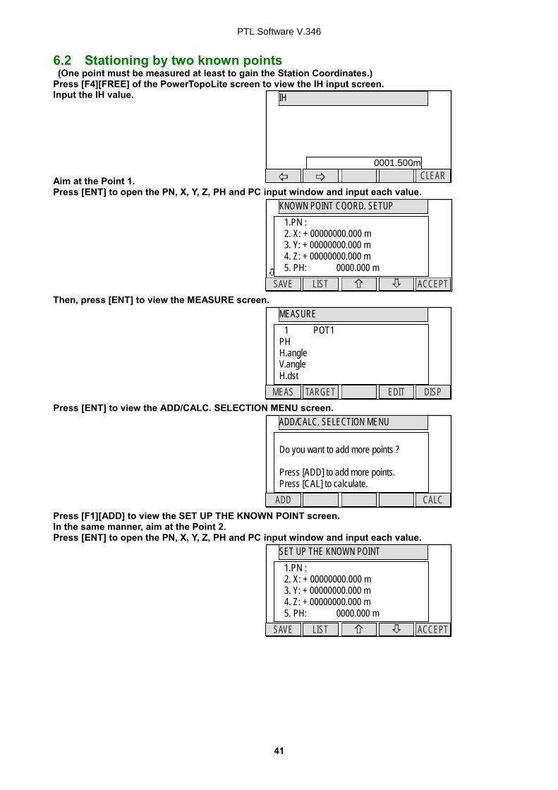
6.2 Stationing by two known points (One point must be measured at least to gain the Station Coordinates.) Press [F4][FREE] of the PowerTopoLite screen to view the IH input screen. Input the IH value. Aim at the Point 1. Press [ENT] to open the PN, X, Y, Z, PH and PC input window and input each value. Then, press [ENT] to view the MEASURE screen. Press [ENT] to view the ADD/CALC. SELECTION MENU screen. Press [F1][ADD] to view the SET UP THE KNOWN POINT screen. In the same manner, aim at the Point 2. Press [ENT] to open the PN, X, Y, Z, PH and PC input window and input each value.
0001.500m
PTL Software V.346
42
RESULT COORD. OF STATIONING
ACCEPT VIEW NEXT
PN HA 0° 00’ 05” X Y Z
MEASURE
EDIT DISP TARGET MEAS
1 POT1 HI H.angle V.angle H dst
ADD/CALC. SELECTION MENU
CALC ADD
Do you want to add more points ? Press [ADD] to add more points. Press [CAL] to calculate
Then, press [ENT] and [ACCEPT] to view the MEASURE screen. Press the [F1][MEAS] to measure the distance. Press [ENT] to view the ADD/CALC. SELECTION MENU screen. Press [ENT] to view the RESULT COORD. OF STATIONING The Station Coordinates is displayed. . Result coordinates of free stationing can be saved for Station setup after pressing [ACCEPT]. Horizontal angle of the result coordinates will be affected to the Station point for measuring. Note:
As illustrated Fig. 1, It is optimal to chooses the known points P1 and P3. The angle of two known points should set up a machine so that it may become 90 degrees. Please install a machine in a position where distance s1 and s2 becomes as same the length as possible. The accuracy of a calculation result falls as follows, 1) When P1 and P2 are chosen for a known point. (The interior angle between known points is extremely small) 2) When P4 and P6 are chosen for a known point. (The interior angle between known points is extremely large) 3) When P4 and P5 are chosen for a known point. ( The interior angle between known points is 180 degrees) 4) When the distance from a new point to a known point is extremely short or extremely long. 5) When a new point (station point) and three or more known points are arranged on the same circumference. (Refer to Fig. 2) ※※※※ When searching for a new point by a FREESTATION and surveying by installing a machine in the
point, accuracy may not be stabilized compared with the case where a machine is installed on a known point. In the work which needs a high-precision survey, we cannot recommend you.
PTL Software V.346
43
STATION POINT H. ANGLE SETUP
HOLD BSP INPUT 0 SET
H. angle 123° 45’ 25”
STAKEOUT METHOD SELECTION
1. STAKE OUT 2. POINT TO LINE
�
STATION POINT SETUP
ACCEPT LIST SAVE
1. PN: 2. X: + 00000000.000 m 3. Y: + 00000000.000 m 4. Z: + 00000000.000 m 5. IH: 0000.000 m
7. STAKE OUT
From the known Station point and Direction angle, the Coordinates for the Stakeout are obtained.
7.1 STAKE OUT Press [F1][STAK] to view the STAKEOUT METHOD SELECTION screen. Select 1.STAKE OUT and press [ENT] to view the STATION POINT SETUP screen. Open the PN, X, Y, Z, IH and PC input window and input each. Save the data by pressing [F1][SAVE]. Press [ENT] to view STATION POINT H ANGLE SETUP screen.
BSP
Stake out Point
Station Point
PTL Software V.346
44
STAKEOUT
PAGE TARGET MEAS
PN POT4 PH X. XXX m
D H.angle XXX° XX’ XX” D V.angle XX° XX’ XX” D H.dst D X D Y D Z
STAKEOUT
NEXT PAGE TARGET MEAS
PN POT4 PH X. XXX m
D H.angle XXX° XX’ XX” D V.angle XX° XX’ XX” D H.dst D X +X. XXX m D Y -X. XXX m D Z +X. XXX m
STAKEOUT COORD. SETUP
ACCEPT LIST SAVE
1. PN: 2. X: + 00000000.000 m 3. Y: + 00000000.000 m 4. Z: + 00000000.000 m 5. PH: 0000.000 m
STAKEOUT
EDIT PAGE STATION H.ANGLE RECT.M
PN POT4 PH X. XXX m
D H.angle XXX° XX’ XX” D V.angle XX° XX’ XX” D H.dst D X +X. XXX m D Y -X. XXX m D Z +X. XXX m
Input the H. angle by pressing [F2][INPUT], [F3][0SET] and [F4] [HOLD] or Backsight Coordinates by pressing [F5][BSP]. Pressing [F2][INPUT] Pressing [F5][BSP] Press [ENT] to view the STAKEOUT COORD. SETUP screen. Open the PN, X, Y, Z, PH and PC input window and input each. Save the data by pressing [F1][SAVE]. Press [ENT] or [ACCEPT] to view the STAKEOUT screen. Aim at the Stake out point and press the [F1][MEAS] to begin the Stake Out. Deviation of each value is displayed. Form of the screen to display deviation of the Stake Out can be changed by the selections of the “Compare method selection” in “PREFERENCE” setting. To display all information at once, To display information with larger character, select “ALL IN ONE INFO.” select “LARGE CHARACTOR”. Press [F5][PAGE] to view another screen.
H.angle
CLEAR
H. angle XXX° XX’ XX”
BSP SETUP
ACCEPT LIST SAVE
1. PN: 2. X: + 00000000.000 m 3. Y: + 00000000.000 m 4. Z: + 00000000.000 m 5. PC:
STAKEOUT
NEXT PAGE TARGET SCROLL MEAS
PN POT4 PH X. XXX m D H.angle XXX° XX’ XX” D V.angle - X° XX’ XX” D H. dist. - m
STAKEOUT
EDIT PAGE STATION H.ANGLE RECT.M
PN POT4 PH X. XXX m D H.angle XXX° XX’ XX” D V.angle - X° XX’ XX” D H. dist. - m
PTL Software V.346
45
MEASURE
PAGE STATION H.ANGLE RECT.M
PN PH 0.000m X Y Z
MEASURE
H.ANGLE PAGE OFFSET STATION REMOTE
PN POT4 PH X. XXX m
D H.angle XXX° XX’ XX” D V.angle XX° XX’ XX” D H.dst D X m D Y m D Z m
MEASURE
NEXT PAGE TARGET SCROLL MEAS
PN PH X Y Z
PAGE
07AA POT4
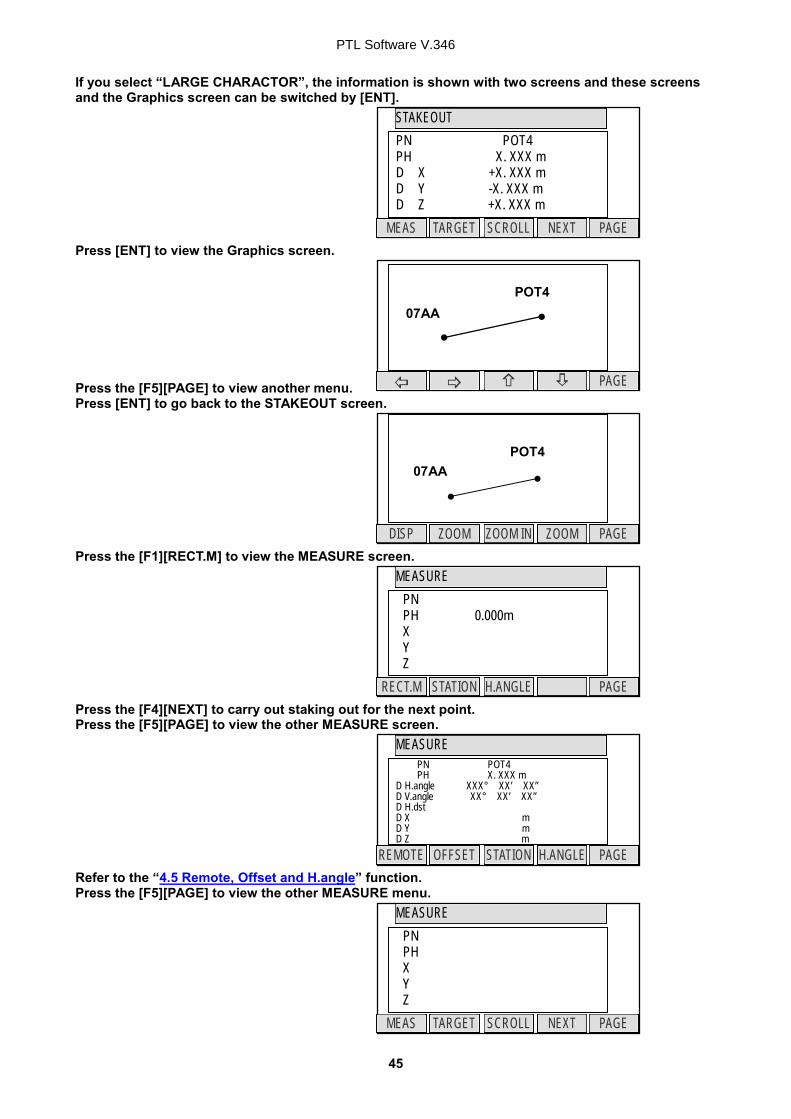
If you select “LARGE CHARACTOR”, the information is shown with two screens and these screens and the Graphics screen can be switched by [ENT]. Press [ENT] to view the Graphics screen. Press the [F5][PAGE] to view another menu. Press [ENT] to go back to the STAKEOUT screen. Press the [F1][RECT.M] to view the MEASURE screen. Press the [F4][NEXT] to carry out staking out for the next point. Press the [F5][PAGE] to view the other MEASURE screen. Refer to the “4.5 Remote, Offset and H.angle” function. Press the [F5][PAGE] to view the other MEASURE menu.
ZOOM PAGE ZOOM ZOOM IN DISP
07AA POT4
STAKEOUT
NEXT PAGE TARGET SCROLL MEAS
PN POT4 PH X. XXX m D X +X. XXX m D Y -X. XXX m D Z +X. XXX m
PTL Software V.346
46
STATION POINT H ANGLE SETUP
HOLD BSP INPUT 0 SET
H. angle 123° 45’ 25”
STATION POINT SETUP
ACCEPT LIST SAVE
1. PN PO1 2. X: + 00000000.000 m 3. Y: + 00000000.000 m 4. Z: + 00000000.000 m 5. IH: 000.000 m
POINT A COORD.SETUP
ACCEPT LIST SAVE
1. PN PO2 2. X: + 00000000.000 m 3. Y: + 00000000.000 m 4. Z: + 00000000.000 m 5. PH: 0000.000 m
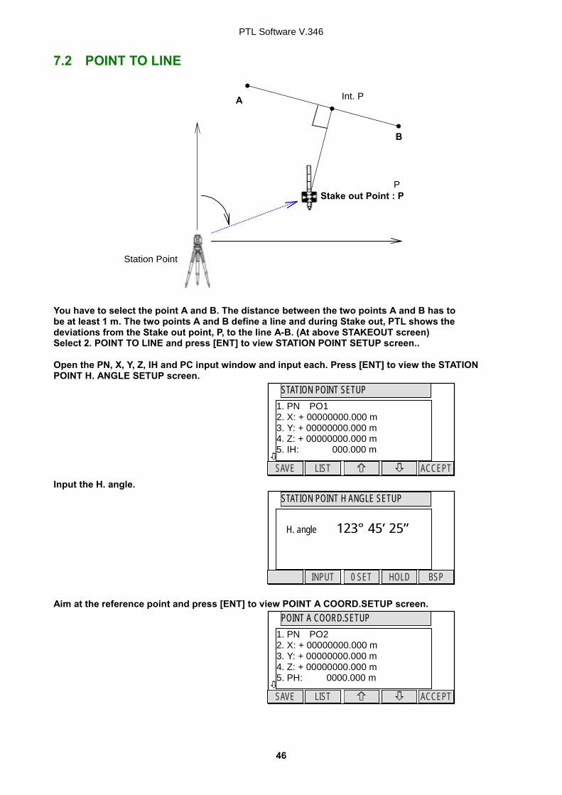
7.2 POINT TO LINE You have to select the point A and B. The distance between the two points A and B has to be at least 1 m. The two points A and B define a line and during Stake out, PTL shows the deviations from the Stake out point, P, to the line A-B. (At above STAKEOUT screen) Select 2. POINT TO LINE and press [ENT] to view STATION POINT SETUP screen.. Open the PN, X, Y, Z, IH and PC input window and input each. Press [ENT] to view the STATION POINT H. ANGLE SETUP screen. Input the H. angle. Aim at the reference point and press [ENT] to view POINT A COORD.SETUP screen.
P
B
A
Stake out Point : P
Station Point
Int. P
PTL Software V.346
47
POINT TO LINE
NEXT PAGE TARGET MEAS
A ->B +0.000 m SOP - > A-B Int.P - > A Int.P - > B
POINT TO LINE
NEXT PAGE TARGET MEAS
A ->B SOP - > A-B Int.P - > A Int.P - > B
POINT B COORD. SETUP
ACCEPT LIST SAVE
1. PN PO3 2. X: + 00000000.000 m 3. Y: + 00000000.000 m 4. Z: + 00000000.000 m 5. PH: 0000.000 m
Open the PN, X, Y, Z, PH and PC input window and input each of the Point A and press [ENT]. Open the PN, X, Y, Z, PH and PC input window and input each of the Point B. Press [ENT] to view the POINT TO LINE screen. Press [F1][MEAS] to measure. Each distance is displayed. A B: Distance between Point A and B. This is always positive. P A – B Distance between Int. P and P, This is positive or negative as shown below. Int.P: Intersection point P: SOP, Stake Out Point Int. P A Distance between Int. P and A, This is positive or negative. Int. P B Distance between Int. P and B, This is positive or negative.
−
Int.P −
+
A B
P
+
Int.P A B
P
−
A B
P
Int.P + −
PTL Software V.346
48
PAGE
ZOOMO PAGE ZOOM ZOOM IN DISP
The arrow direction is positive. Press [ENT] to display the Graphics. Graphics are moved by each arrow key. Press the [F5][PAGE] to change the menu. Refer to the Graphical view of the “5. VIEW AND EDIT” function concerning each key function.
8. CALCULATIONS The following calculations are available: COGO
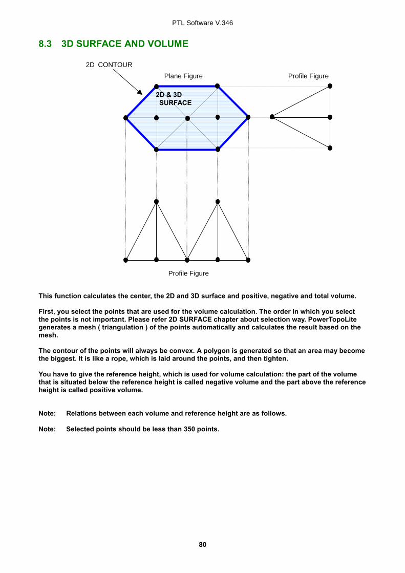
2D SURFACE 3D SURFACE & VOLUME REM
8.1 COGO The following COGO functions are available: Inverse Points Coordinates Circle Radius Line-Arc Intersection Line-Line Intersection Arc-Arc Intersection Distance Offset Point Distance Offset Arc Distance Offset
8.1.1 INVERSE From the given two points Coordinates, the Direction angle and distance are calculated. Input: Coordinates of two points Output: Horizontal distance, Vertical distance between the points and Direction of the line defined by the two points From the PowerTopoLite screen, press [F2][CALC] to view CALCULATION screen.
EP: End Point
SP: Start Point
PTL Software V.346
50
COGO
1. INVERSE 2. POINT COORDINATES 3. CIRCLE RADIUS 4. LINE-ARC INTERSECTION 5. LINE-LINE INTERSECTION
6 ARC ARC IINTERSEVTION
INVERSE
1. SP 2. EP
SP
ACCEPT LIST SAVE
1. PN: 2. X: + 00000000.000 m 3. Y: + 00000000.000 m 4. Z: + 00000000.000 m 5. PC:
POINT SELECTION FROM THE LIST
FIND PN DELETE
1 / 15 1. PN:POT1 2. X: + 00000000.000 m 3. Y: + 00000000.000 m 4. Z: + 00000000.000 m
X
CLEAR
1. PN: POT1 2. X: + 00000000.000 m 3. Y: + 00000000.000 m 4. Z: + 00000000.000 m 5. PC:
SP
ACCEPT LIST SAVE
1. PN: 2. X: + 00000000.000 m 3. Y: + 00000000.000 m 4. Z: + 00000000.000 m 5. PC:
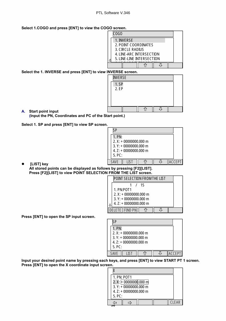
Select 1.COGO and press [ENT] to view the COGO screen. Select the 1. INVERSE and press [ENT] to view INVERSE screen. A. Start point input (Input the PN, Coordinates and PC of the Start point.) Select 1. SP and press [ENT] to view SP screen. [LIST] key
All stored points can be displayed as follows by pressing [F2][LIST]. Press [F2][LIST] to view POINT SELECTION FROM THE LIST screen. Press [ENT] to open the SP input screen. Input your desired point name by pressing each keys, and press [ENT] to view START PT 1 screen. Press [ENT] to open the X coordinate input screen.
PTL Software V.346
51
Y
CLEAR
1. PN: POT1 2. X: + 00000000.000 m 3. Y: + 00000000.000 m 4. Z: + 00000000.000 m 5. PC:
Z
CLEAR
1. PN: POT1 2. X: + 00000000.000 m 3. Y: + 00000000.000 m 4. Z: + 00000000.000 m 5. PC:
SP
ACCEPT LIST SAVE
1. PN: 2. X: + 00000000.000 m 3. Y: + 00000000.000 m 4. Z: + 00000000.000 m 5. PC:
PC
CLEAR
1. PN: POT1 2. X: + 00000000.000 m 3. Y: + 00000000.000 m 4. Z: + 00000000.000 m 5. PC: .
EP
ACCEPT LIST SAVE
1. PN: 2. X: + 00000000.000 m 3. Y: + 00000000.000 m 4. Z: + 00000000.000 m 5. PC:
Z
CLEAR
1. PN: POT1 2. X: + 00000000.000 m 3. Y: + 00000000.000 m 4. Z: + 00000000.000 m 5. PC:
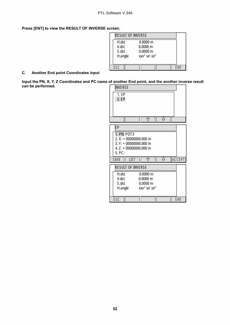
Input your desired value by pressing each keys and press [ENT] to go Y coordinate. Press [ENT] to open the Y coordinate input screen and input. Press [ENT] to open the Z coordinate input screen and input. Press [ENT] to open the PC input screen and input. B. End point coordinates input (Input the PN , Coordinates and PC of the End point.) After PC input, EP screen is viewed. Input the PN, X, Y, Z Coordinates and PC name of the End point.
PTL Software V.346
52
RESULT OF INVERSE
ENT ESC
H.dst 0.0000 m V.dst 0.0000 m S.dst 0.0000 m H.angle xxx° xx’ xx”
INVERSE
1. SP 2. EP
EP
ACCEPT LIST SAVE
1. PN: POT3 2. X: + 00000000.000 m 3. Y: + 00000000.000 m 4. Z: + 00000000.000 m 5. PC:
RESULT OF INVERSE
ENT ESC
H.dst 0.0000 m V.dst 0.0000 m S.dst 0.0000 m H.angle xxx° xx’ xx”
Press [ENT] to view the RESULT OF INVERSE screen. C. Another End point Coordinates input Input the PN, X, Y, Z Coordinates and PC name of another End point, and the another inverse result can be performed.
PTL Software V.346
53
POINT COORDINATES
1. CO 2. DI 3. BE
COGO
1. INVERSE 2. POINT COORDINATES 3. CIRCLE RADIUS 4. LINE-ARC INTERSECTION 5. LINE-LINE INTERSECTION
6 ARC ARC IINTERSEVTION
CALCULATION
1. COGO 2. 2D SURFACE 3. 3D SURFACE & VOLUME 4. REM
CO
ACCEPT LIST SAVE
1. PN: 2. X: + 00000000.000 m 3. Y: + 00000000.000 m 4. Z: + 00000000.000 m 5. PC:
8.1.2 POINTS COORDINATES A point Coordinates is calculated from a known point Coordinates and the Distance and Horizontal angle of the second point. Input: Coordinates of a known point, Distance and Horizontal angle of the second point Output: Coordinates of the second point From the PowerTopoLite screen, press [F2][CALC] to view the CALCULATION screen. Select 1.COGO and press [ENT] to view the COGO screen.
8.1.2.1 Point Coordinates, Distance and H. angle Select the 2. POINT COORDINATES and press [ENT] to view POINT COORINATES screen. Select 1. CO and press [ENT] to view CO screen.
Bearing
Distance
First Point
PTL Software V.346
54
PN
CLEAR TO 123 BS
1. PN: . 2. X: + 00000000.000 m 3. Y: + 00000000.000 m 4. Z: + 00000000.000 m 5. PC:
CO
ACCEPT LIST SAVE
1. PN: 2. X: + 00000000.000 m 3. Y: + 00000000.000 m 4. Z: + 00000000.000 m 5. PC:
X
CLEAR
1. PN: POI1 2. X: + 00000000.000 m 3. Y: + 00000000.000 m 4. Z: + 00000000.000 m 5. PC:
CO
ACCEPT LIST SAVE
1. PN: 2. X: + 00000000.000 m 3. Y: + 00000000.000 m 4. Z: + 00000000.000 m 5. PC:
Y
CLEAR
1. PN: POT1 2. X: + 00000000.000 m 3. Y: + 00000000.000 m 4. Z: + 00000000.000 m 5. PC:
Z
CLEAR
1. PN: POT1 2. X: + 00000000.000 m 3. Y: + 00000000.000 m 4. Z: + 00000000.000 m 5. PC:
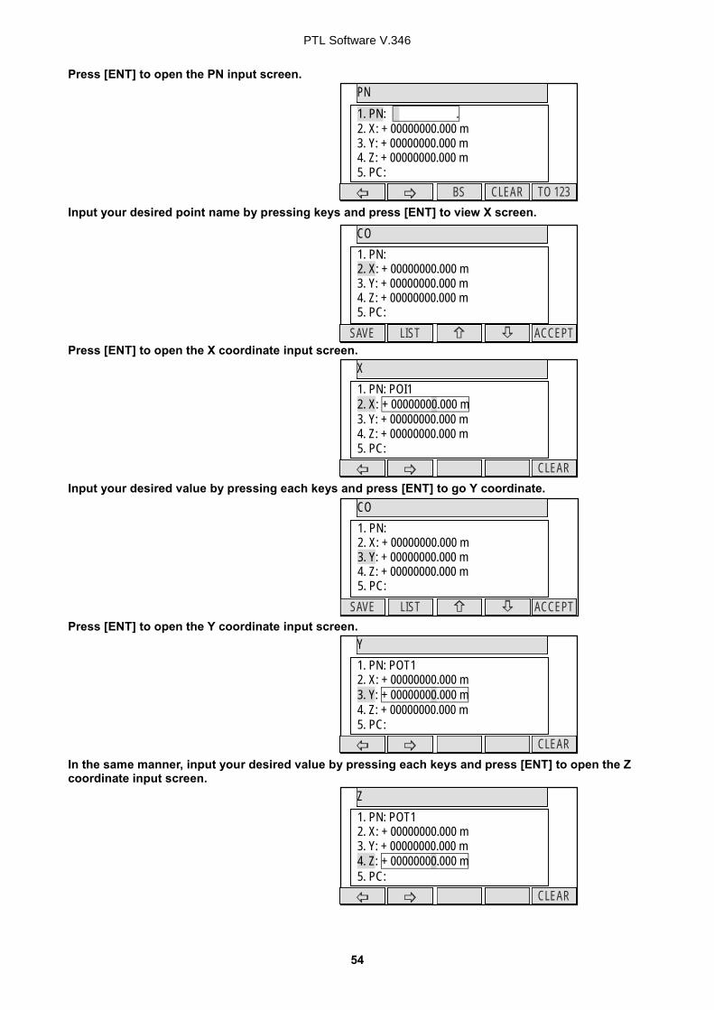
Press [ENT] to open the PN input screen. Input your desired point name by pressing keys and press [ENT] to view X screen. Press [ENT] to open the X coordinate input screen. Input your desired value by pressing each keys and press [ENT] to go Y coordinate. Press [ENT] to open the Y coordinate input screen. In the same manner, input your desired value by pressing each keys and press [ENT] to open the Z coordinate input screen.
PTL Software V.346
55
PC
CLEAR
1. PN: POT1 2. X: + 00000000.000 m 3. Y: + 00000000.000 m 4. Z: + 00000000.000 m 5. PC: .
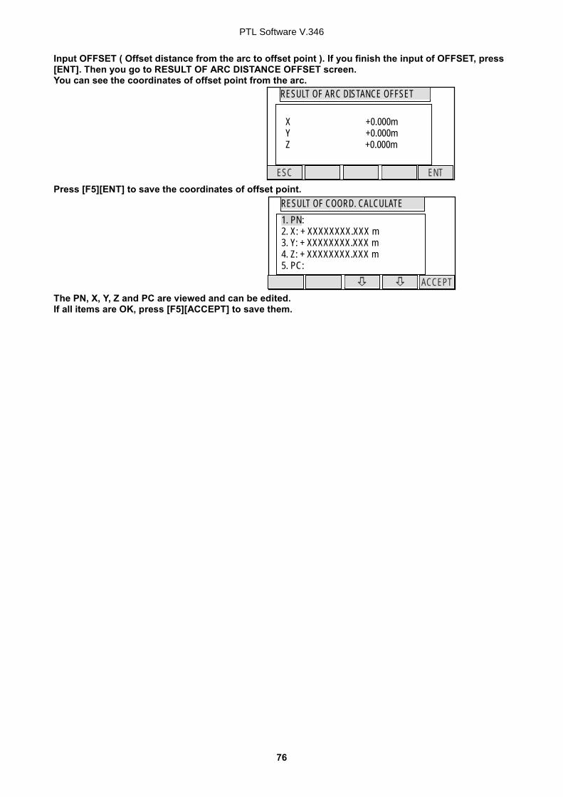
Input your desired value by pressing each keys and press [ENT] to open the PC, Point Code, input screen. Input your desired PC by pressing each keys, and press [ENT] to view DI screen. Input your desired value and press [ENT] to open the H. ANGLE input window. Input your desired value to view the RESULT OF COORD. CALCULATE screen. The second point Coordinates are displayed by plus or minus from the known Coordinates. Press [ENT] to view the following screen. The PN, X, Y, Z and PC are viewed and can be edited. If all items are OK, press [F1][SAVE] or [F5][ACCEPT] to save them.
DISTANCE
CLEAR
0000.000m
H. angle
CLEAR
000° 00’ 00”
RESULT OF COORD. CALCULATE
ENT ESC
X +0.000m Y +0.000m Z +0.000m
ACCEPT SAVE
RESULT OF COORD. CALCULATE 1. PN: 2. X: + XXXXXXXX.XXX m 3. Y: + XXXXXXXX.XXX m 4. Z: + XXXXXXXX.XXX m 5. PC:
PTL Software V.346
56
8.1.2.2 Distance and H. angle In the same manner, the values of Distance and H. angle are inputted as follows and the second point Coordinates are displayed. Select 2. DI and press [ENT] to view DI screen. Input your desired value and press [ENT] to open the H. ANGLE input window. Input your desired value to view the RESULT OF COORD. CALCULATE screen. The second point Coordinates are displayed by plus or minus from the known Coordinates. Press [ENT] to view the following screen. The PN, X, Y, Z and PC are viewed and can be edited. If all items are OK, press [F1][SAVE] or [F5][ACCEPT] to save them.
POINT COORDINATES
1. CO 2. DI. 3. BE
DISTANCE
CLEAR
0000.000m
H.angle
CLEAR
000° 00’ 00”
RESULT OF COORD. CALCULATE
ENT ESC
X +0.000m Y +0.000m Z +0.000m
ACCEPT LIST SAVE
RESULT OF COORD. CALCULATE 1. PN: 2. X: + XXXXXXXX.XXX m 3. Y: + XXXXXXXX.XXX m 4. Z: + XXXXXXXX.XXX m 5. PC:
PTL Software V.346
57
8.1.2.3 H. angle input In the same manner, only the value of H. angle is inputted as follows, and the second point Coordinates are displayed. Select 3. BE and press [ENT] to view H. ANGLE screen. Input H. angle and press [ENT] to view the RESULT OF COORD. CALCULATE screen. The second point Coordinates are displayed by plus or minus from the known Coordinates. Press [ENT] to view the following screen. The PN, X, Y, Z and PC are viewed and can be edited. If all items are OK, press [F1][SAVE] or [F5][ACCEPT] to save them.
POINT COORDINATES
1. CO 2. DI 2. DI
H. ANGLE
CLEAR
000° 00’ 00”
RESULT OF COORD. CALCULATE
ENT ESC
X +0.000m Y +0.000m Z +0.000m
ACCEPT LIST SAVE
RESULT OF COORD. CALCULATE 1. PN: 2. X: + XXXXXXXX.XXX m 3. Y: + XXXXXXXX.XXX m 4. Z: + XXXXXXXX.XXX m 5. PC:
1. INVERSE 2. POINT COORDINATES 3. CIRCLE RADIUS 4. LINE-ARC INTERSECTION 5. LINE-LINE INTERSECTION
6 ARC ARC IINTERSEVTION
8.1.3 CIRCLE RADIUS The center point and radius of the circle drawn by three points are calculated by this function. You can store calculated center point. Input: 3 points Output: Center point of the arc Radius of the arc From the PowerTopoLite screen, press [F2][CALC] to view the CALCULATION screen. Select 1.COGO and press [ENT] to view the COGO screen. Select the 3. CIRCLE RADIUS and press [ENT] to view CIRCLE RADIUS screen.
P2
P3
P1
Radius
Center P
CIRCLE RADIUS
1. P1 2. P2 3. P3
PTL Software V.346
59
Select 1. P1 and press [ENT] to view P1 screen. Input PN ( Point Name ), X, Y, Z, and PC ( Point Code ) of P1 point or import from the memory of rectangular coordinate as P1 by [F2][LIST]. If you finish the input of P1 value, press [F5][ACCEPT]. Then you go to P2 input screen. Input P2 data like input of P1. If you finish the input of P2, press [F5][ACCEPT]. Then you go to P3 input screen. If you finish the input of P3, press [F5][ACCEPT]. Then you go to RESULT OF CIRCLE RADIUS screen. You can see the coordinates of center point of the arc and the radius of the arc. Press [F5][ENT] to save the coordinates of center point. The PN, X, Y, Z and PC are viewed and can be edited. If all items are OK, press [F5][ACCEPT] to save them.
P1
ACCEPT LIST SAVE
1. PN: 2. X: + 00000000.000 m 3. Y: + 00000000.000 m 4. Z: + 00000000.000 m 5. PC:
P2
ACCEPT LIST SAVE
1. PN: 2. X: + 00000000.000 m 3. Y: + 00000000.000 m 4. Z: + 00000000.000 m 5. PC:
P3
ACCEPT LIST SAVE
1. PN: 2. X: + 00000000.000 m 3. Y: + 00000000.000 m 4. Z: + 00000000.000 m 5. PC:
RESULT OF CIRCLE RADIUS
ENT ESC
X +0.000m Y +0.000m Z +0.000m RADIUS +0.000m
ACCEPT
RESULT OF CIRCLE RADIUS 1. PN: 2. X: + XXXXXXXX.XXX m 3. Y: + XXXXXXXX.XXX m 4. Z: + XXXXXXXX.XXX m 5. PC:
1. INVERSE 2. POINT COORDINATES 3. CIRCLE RADIUS 4. LINE-ARC INTERSECTION 5. LINE-LINE INTERSECTION
6 ARC ARC IINTERSEVTION
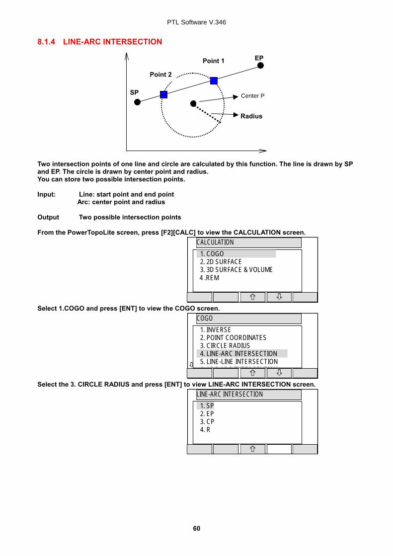
8.1.4 LINE-ARC INTERSECTION Two intersection points of one line and circle are calculated by this function. The line is drawn by SP and EP. The circle is drawn by center point and radius. You can store two possible intersection points. Input: Line: start point and end point Arc: center point and radius Output Two possible intersection points From the PowerTopoLite screen, press [F2][CALC] to view the CALCULATION screen. Select 1.COGO and press [ENT] to view the COGO screen. Select the 3. CIRCLE RADIUS and press [ENT] to view LINE-ARC INTERSECTION screen.
EP
SP
Radius
Center P
Point 1
Point 2
LINE-ARC INTERSECTION
�
1. SP 2. EP 3. CP 4. R
PTL Software V.346
61
Select 1. SP and press [ENT] to view SP screen. Input PN ( Point Name ), X, Y, Z, and PC ( Point Code ) of SP point or import from the memory of rectangular coordinate as SP by [F2][LIST]. If you finish the input of SP value, press [F5][ACCEPT]. Then you go to EP input screen. Input EP value like an input of SP. If you finish an input of P2, press [F5][ACCEPT]. Then you go to CP input screen. If you finish the input of CP value, press [F5][ACCEPT]. Then you go to RADIUS input screen. If you finish the input of RADIUS, press [ENT]. Then you go to RESULT OF LINE-ARC INTERSECTION screen. You can see the coordinates of one of intersection point. You can switch to one more intersection point by pressing [F3][ONE MORE].
SP
ACCEPT LIST SAVE
1. PN: 2. X: + 00000000.000 m 3. Y: + 00000000.000 m 4. Z: + 00000000.000 m 5. PC:
EP
ACCEPT LIST SAVE
1. PN: 2. X: + 00000000.000 m 3. Y: + 00000000.000 m 4. Z: + 00000000.000 m 5. PC:
CP
ACCEPT LIST SAVE
1. PN: 2. X: + 00000000.000 m 3. Y: + 00000000.000 m 4. Z: + 00000000.000 m 5. PC:
RESULT OF LINE-ARC INTERSECT.
ENT ONE MORE ESC
X +0.000m Y +0.000m Z +0.000m
RADIUS
CLEAR
0000.000m
PTL Software V.346
62
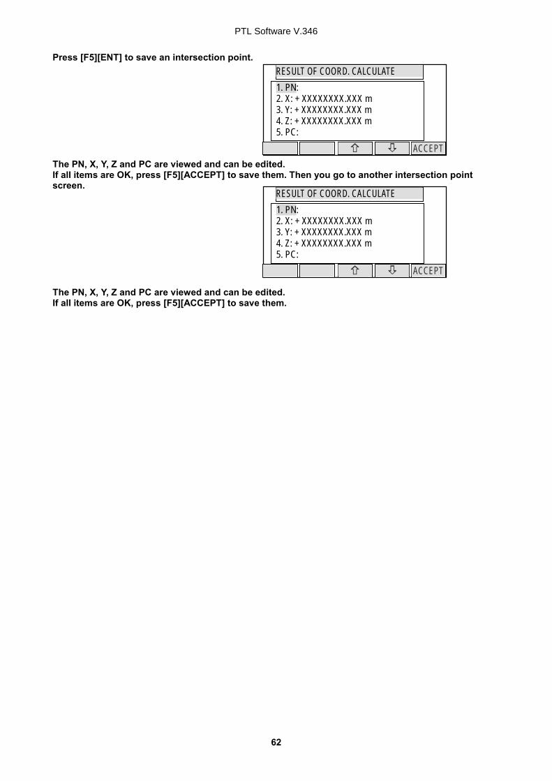
Press [F5][ENT] to save an intersection point. The PN, X, Y, Z and PC are viewed and can be edited. If all items are OK, press [F5][ACCEPT] to save them. Then you go to another intersection point screen. The PN, X, Y, Z and PC are viewed and can be edited. If all items are OK, press [F5][ACCEPT] to save them.
ACCEPT
RESULT OF COORD. CALCULATE 1. PN: 2. X: + XXXXXXXX.XXX m 3. Y: + XXXXXXXX.XXX m 4. Z: + XXXXXXXX.XXX m 5. PC:
ACCEPT
RESULT OF COORD. CALCULATE 1. PN: 2. X: + XXXXXXXX.XXX m 3. Y: + XXXXXXXX.XXX m 4. Z: + XXXXXXXX.XXX m 5. PC:
1. INVERSE 2. POINT COORDINATES 3. CIRCLE RADIUS 4. LINE-ARC INTERSECTION 5. LINE-LINE INTERSECTION
6 ARC ARC IINTERSEVTION
8.1.5 LINE-LINE INTERSECTION The intersection point of two lines drawn by given two points is calculated by this Function. Input: First line : Start point and End point Second line: Start point and End point Output: Intersection point between the two lines From the PowerTopoLite screen, press the [F2][CALC] to view the CALCULATION screen. Press 1.COGO to view the COGO screen. Select 5. LINE-LINE INTERSECTION and press [ENT] to view its screen.
S2
E2 S1
E1 Intersection P
LINE-LINE INTERSECTION
1. S1 2. E1 3. S2 4. E2
PTL Software V.346
64
PN
CLEAR TO 123 BS
1. PN: . 2. X: + 00000000.000 m 3. Y: + 00000000.000 m 4. Z: + 00000000.000 m 5. PC:
S1
ACCEPT LIST SAVE
1. PN: 2. X: + 00000000.000 m 3. Y: + 00000000.000 m 4. Z: + 00000000.000 m 5. PC:
X
CLEAR
1. PN: POI1 2. X: + 00000000.000 m 3. Y: + 00000000.000 m 4. Z: + 00000000.000 m 5. PC:
S1
ACCEPT LIST SAVE
1. PN: 2. X: + 00000000.000 m 3. Y: + 00000000.000 m 4. Z: + 00000000.000 m 5. PC:
Y
CLEAR
1. PN: POT1 2. X: + 00000000.000 m 3. Y: + 00000000.000 m 4. Z: + 00000000.000 m 5. PC:
Select 1.S1 and press [ENT] to view its screen. Press [ENT] to open the PN input screen. Input your desired point name by pressing each keys, and press [ENT] to view X screen. Press [ENT] to open the X coordinate input screen. Input your desired value by pressing each keys and press [ENT] to go Y coordinate. Press [ENT] to open the Y coordinate input screen.
S1
ACCEPT LIST SAVE
1. PN: 2. X: + 00000000.000 m 3. Y: + 00000000.000 m 4. Z: + 00000000.000 m
5. PC:
PTL Software V.346
65
Z
CLEAR
1. PN: POT1 2. X: + 00000000.000 m 3. Y: + 00000000.000 m 4. Z: + 00000000.000 m 5. PC:
PC
CLEAR
1. PN: POT1 2. X: + 00000000.000 m 3. Y: + 00000000.000 m 4. Z: + 00000000.000 m 5. PC: .
E1
ACCEPT LIST SAVE
1. PN: 2. X: + 00000000.000 m 3. Y: + 00000000.000 m 4. Z: + 00000000.000 m 5. PC:
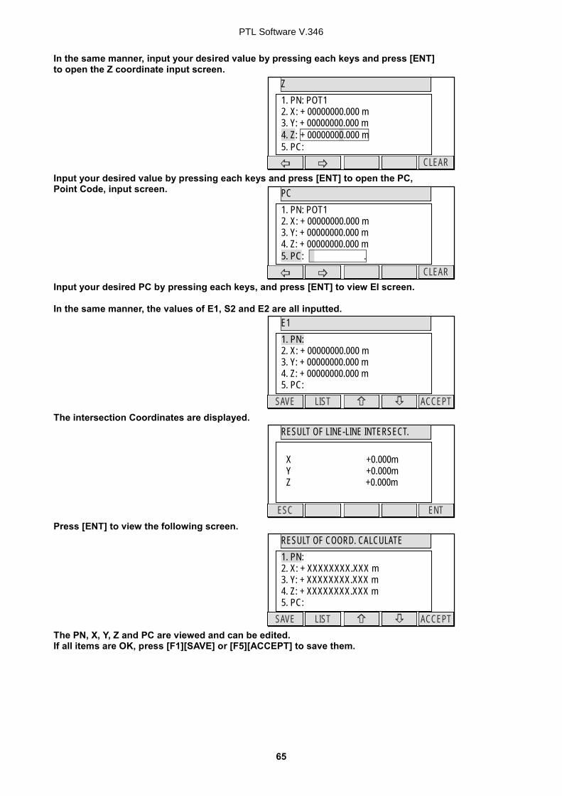
In the same manner, input your desired value by pressing each keys and press [ENT] to open the Z coordinate input screen. Input your desired value by pressing each keys and press [ENT] to open the PC, Point Code, input screen. Input your desired PC by pressing each keys, and press [ENT] to view EI screen. In the same manner, the values of E1, S2 and E2 are all inputted. The intersection Coordinates are displayed. Press [ENT] to view the following screen. The PN, X, Y, Z and PC are viewed and can be edited. If all items are OK, press [F1][SAVE] or [F5][ACCEPT] to save them.
RESULT OF LINE-LINE INTERSECT.
ENT ESC
X +0.000m Y +0.000m Z +0.000m
ACCEPT LIST SAVE
RESULT OF COORD. CALCULATE 1. PN: 2. X: + XXXXXXXX.XXX m 3. Y: + XXXXXXXX.XXX m 4. Z: + XXXXXXXX.XXX m 5. PC:
8.1.6 ARC-ARC INTERSECTION Two intersection points of two arcs drawn by each center point and radius are calculated. You can store two possible intersection points. Input: Arc 1: center point and radius
Arc 2: center point and radius Output: Two possible intersection points From the PowerTopoLite screen, press [F2][CALC] to view the CALCULATION screen. Select 1.COGO and press [ENT] to view the COGO screen. Select the 6. ARC-ARC INTERSECTION and press [ENT] to view ARC-ARC INTERSECTION screen.
Radius 2 Center 2
Point 1
Point 2
Radius 1
Center 1
Arc 1
Arc 2
LINE-ARC INTERSECTION
1. C1 2. R1 3. C2 4. R2
PTL Software V.346
67
Select 1. C1 and press [ENT] to view C1 screen. C1 ( Center 1 ) point is center point of Arc 1. Input PN ( Point Name ), X, Y, Z, and PC ( Point Code ) of C1 point or import from the memory of rectangular coordinate as C1 by [F2][LIST]. If you finish the input of C1 value, press [F5][ACCEPT]. Then you go to R1 input screen. Input the radius of Arc 1 as R1 value. If you finish the input of R1, press [F5][ACCEPT]. Then you go to C2 input screen. C2 ( Center 2 ) point is center point of Arc 2. Input PN ( Point Name ), X, Y, Z, and PC ( Point Code ) of C2 point or import from the memory of rectangular coordinate as C2 by [F2][LIST]. If you finish the input of C2 value, press [F5][ACCEPT]. Then you go to R2 input screen. Input the radius of Arc 2 as R2 value. If you finish the input of R2, press [ENT]. Then you go to RESULT OF LINE-ARC INTERSECTION screen. You can see the coordinates of one of intersection point. You can switch to one more intersection point by pressing [F3][ONE MORE].
C1
ACCEPT LIST SAVE
1. PN: 2. X: + 00000000.000 m 3. Y: + 00000000.000 m 4. Z: + 00000000.000 m 5. PC:
R1
CLEAR
000.000m
C2
ACCEPT LIST SAVE
1. PN: 2. X: + 00000000.000 m 3. Y: + 00000000.000 m 4. Z: + 00000000.000 m 5. PC:
R2
CLEAR
000.000m
RESULT OF ARC-ARC INTERSECT.
ENT ONE MORE ESC
X +0.000m Y +0.000m Z +0.000m
PTL Software V.346
68
Press [F5][ENT] to save one of intersection point. The PN, X, Y, Z and PC are viewed and can be edited. If all items are OK, press [F5][ACCEPT] to save them. Then you go to another intersection point screen. The PN, X, Y, Z and PC are viewed and can be edited. If all items are OK, press [F5][ACCEPT] to save them.
ACCEPT
RESULT OF COORD. CALCULATE 1. PN: 2. X: + XXXXXXXX.XXX m 3. Y: + XXXXXXXX.XXX m 4. Z: + XXXXXXXX.XXX m 5. PC:
ACCEPT
RESULT OF COORD. CALCULATE 1. PN: 2. X: + XXXXXXXX.XXX m 3. Y: + XXXXXXXX.XXX m 4. Z: + XXXXXXXX.XXX m 5. PC:
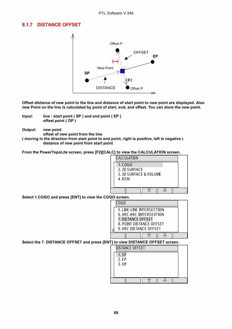
8.1.7 DISTANCE OFFSET (――――) (++++) Offset distance of new point to the line and distance of start point to new point are displayed. Also new Point on the line is calculated by point of start, end, and offset. You can store the new point. Input: line : start point ( SP ) and end point ( EP )
offset point ( OP ) Output: new point offset of new point from the line ( moving in the direction from start point to end point, right is positive, left is negative ) distance of new point from start point From the PowerTopoLite screen, press [F2][CALC] to view the CALCULATION screen. Select 1.COGO and press [ENT] to view the COGO screen. Select the 7. DISTANCE OFFSET and press [ENT] to view DISTANCE OFFSET screen.
New Point SP
EP
Offset P
DISTANCE
OFFSET
DISTANCE OFFSET
1. SP 2. EP 3. OP
Offset P
PTL Software V.346
70
Select 1. SP and press [ENT] to view SP screen. Input PN ( Point Name ), X, Y, Z, and PC ( Point Code ) of SP point or import from the memory of rectangular coordinate as SP by [F2][LIST]. If you finish the input of SP value, press [F5][ACCEPT]. Then you go to EP input screen. Input EP data like input of SP. If you finish the input of EP, press [F5][ACCEPT]. Then you go to OP input screen. If you finish the input of OP, press [F5][ACCEPT]. Then you go to RESULT OF DISTANCE OFFSET screen. You can see the coordinates of new point on the line, offset distance of new point to the line and distance of new point to start point. Press [F5][ENT] to save the coordinates of new point. The PN, X, Y, Z and PC are viewed and can be edited. If all items are OK, press [F5][ACCEPT] to save them.
SP
ACCEPT LIST SAVE
1. PN: 2. X: + 00000000.000 m 3. Y: + 00000000.000 m 4. Z: + 00000000.000 m 5. PC:
EP
ACCEPT LIST SAVE
1. PN: 2. X: + 00000000.000 m 3. Y: + 00000000.000 m 4. Z: + 00000000.000 m 5. PC:
OP
ACCEPT LIST SAVE
1. PN: 2. X: + 00000000.000 m 3. Y: + 00000000.000 m 4. Z: + 00000000.000 m 5. PC:
RESULT OF DISTANCE OFFSET
ENT ESC
X +0.000m Y +0.000m Z +0.000m DISTANCE +0.000m OFFSET +0.000m
ACCEPT
RESULT OF COORD. CALCULATE 1. PN: 2. X: + XXXXXXXX.XXX m 3. Y: + XXXXXXXX.XXX m 4. Z: + XXXXXXXX.XXX m 5. PC:
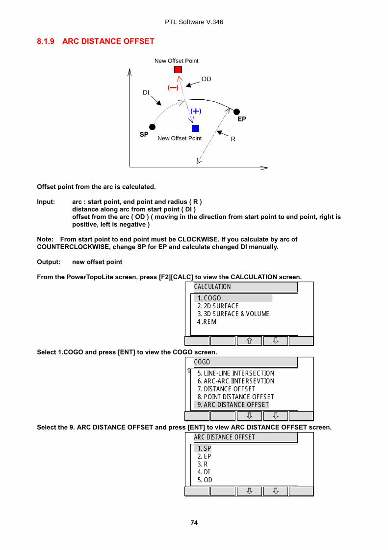
8.1.8 POINT DISTANCE OFFSET (――――) (++++) New offset point is calculated by inputting distance from start point and offset from line. Input: line : start point and end point
distance from start point (DI ) offset from the line ( OD ) ( moving in the direction from start point to end point, right is
positive, left is negative ) Output: new point From the PowerTopoLite screen, press [F2][CALC] to view the CALCULATION screen. Select 1.COGO and press [ENT] to view the COGO screen. Select the 8. POINT DISTANCE OFFSET and press [ENT] to view POINT DISTANCE OFFSET screen.
Select 1. SP and press [ENT] to view SP screen. Input PN ( Point Name ), X, Y, Z, and PC ( Point Code ) of SP point or import from the memory of rectangular coordinate as SP by [F2][LIST]. If you finish the input of SP value, press [F5][ACCEPT]. Then you go to EP input screen. Input EP data like input of SP. If you finish the input of EP, press [F5][ACCEPT]. Then you go to DISTANCE input screen. Input DI ( Distance from SP to point on the line ). If you finish the input of DI, press [F5][ACCEPT]. Then you go to OFFSET input screen. Input OD ( Offset distance from the line to offset point ). If you finish the input of OD, press [F5][ACCEPT]. Then you go to RESULT OF POINT DISTANCE OFFSET screen. You can see the coordinates of offset point from the line.
SP
ACCEPT LIST SAVE
1. PN: 2. X: + 00000000.000 m 3. Y: + 00000000.000 m 4. Z: + 00000000.000 m 5. PC:
EP
ACCEPT LIST SAVE
1. PN: 2. X: + 00000000.000 m 3. Y: + 00000000.000 m 4. Z: + 00000000.000 m 5. PC:
RESULT OF POINT DISTANCE OFFSET
ENT ESC
X +0.000m Y +0.000m Z +0.000m
DISTANCE
CLEAR
0000.000m
OFFSET
CLEAR
0000.000m
PTL Software V.346
73
Press [F5][ENT] to save the coordinates of offset point. The PN, X, Y, Z and PC are viewed and can be edited. If all items are OK, press [F5][ACCEPT] to save them.
ACCEPT
RESULT OF COORD. CALCULATE 1. PN: 2. X: + XXXXXXXX.XXX m 3. Y: + XXXXXXXX.XXX m 4. Z: + XXXXXXXX.XXX m 5. PC:
8.1.9 ARC DISTANCE OFFSET (――――) (++++) Offset point from the arc is calculated. Input: arc : start point, end point and radius ( R ) distance along arc from start point ( DI ) offset from the arc ( OD ) ( moving in the direction from start point to end point, right is positive, left is negative ) Note: From start point to end point must be CLOCKWISE. If you calculate by arc of COUNTERCLOCKWISE, change SP for EP and calculate changed DI manually. Output: new offset point From the PowerTopoLite screen, press [F2][CALC] to view the CALCULATION screen. Select 1.COGO and press [ENT] to view the COGO screen. Select the 9. ARC DISTANCE OFFSET and press [ENT] to view ARC DISTANCE OFFSET screen.
Select 1. SP and press [ENT] to view SP screen. Input PN ( Point Name ), X, Y, Z, and PC ( Point Code ) of SP point or import from the memory of rectangular coordinate as SP by [F2][LIST]. If you finish the input of SP value, press [F5][ACCEPT]. Then you go to EP input screen. Input EP data like an input of SP. If you finish input of EP, press [F5][ACCEPT]. Then you go to RADIUS input screen. Input RADIUS ( Radius of circle ). If you finish the input of RADIUS, press [ENT]. Then you go to DISTANCE input screen. Input DI STANCE ( Distance from SP to point on the arc ). If you finish the input of DISTANCE, press [ENT]. Then you go to OFFSET input screen.
SP
ACCEPT LIST SAVE
1. PN: 2. X: + 00000000.000 m 3. Y: + 00000000.000 m 4. Z: + 00000000.000 m 5. PC:
EP
ACCEPT LIST SAVE
1. PN: 2. X: + 00000000.000 m 3. Y: + 00000000.000 m 4. Z: + 00000000.000 m 5. PC:
RADIUS
CLEAR
0000.000m
DISTANCE
CLEAR
0000.000m
OFFSET
CLEAR
0000.000m
PTL Software V.346
76
Input OFFSET ( Offset distance from the arc to offset point ). If you finish the input of OFFSET, press [ENT]. Then you go to RESULT OF ARC DISTANCE OFFSET screen. You can see the coordinates of offset point from the arc. Press [F5][ENT] to save the coordinates of offset point. The PN, X, Y, Z and PC are viewed and can be edited. If all items are OK, press [F5][ACCEPT] to save them.
RESULT OF ARC DISTANCE OFFSET
ENT ESC
X +0.000m Y +0.000m Z +0.000m
ACCEPT
RESULT OF COORD. CALCULATE 1. PN: 2. X: + XXXXXXXX.XXX m 3. Y: + XXXXXXXX.XXX m 4. Z: + XXXXXXXX.XXX m 5. PC:
8.2 2D SURFACE This function calculates the 2D and 3D contour of a polygon and the 2D surface of the area defined by the polygon. You define the polygon by selecting points and PowerTopoLite then calculates contour and 2D surface. Note: The polygon is defined by the point you select. Therefore, the order in which you enter the point is important. If you select points by [ALL] or [FROM][TO], the polygon is defined according to the order of the memory address. If you select points one by one by [ENT], the polygon is defined according to the order of your selection. Note: You have to select points in such a way that the line segments that define the polygon do not intersect. Note: Selected points should be less than 1500 points. From the PowerTopoLite screen, press [F2][CALC] to view the CALCULATION screen.
2D SURFACE
2D CONTOUR
3D CONTOUR
X
Y
Z
STORED POINTS
PTL Software V.346
78
Select 2. 2D SURFACE and press [ENT] to view POINT SELECTION FROM THE LIST screen.
If you press [F5][PAGE], you can see another screen. You select points, which defines the polygon in order at this screen. How to select points of polygon
[ENT] key Move to selection point by [F3] and [F4] arrow keys and press [ENT] to select it one by one and each indication is reversed as follows. Reverse display shows that it was selected. If you cancel the selection of the point, press [ENT] again. And you can cancel the selection point one by one after pressing [ALL].
[F2][ALL] key Press [F2][ALL] to select all stored points of current JOB. The order of points is according to the arrangement of the memory. if you press [F2][ALL] again, the selection of all points are canceled. You can cancel the selection point by [ENT] one by one after pressing [ALL]. If you press [F2][ALL] after you already selected some points, the selection of each points are reversed. [F3][FROM] key and [F4][TO] key You can define the range of polygonal points from all points of current JOB by [F3][FROM] and [F4][TO] as follows.
POINT SELECTION FROM THE LIST
PAGE ALL ACCEPT
10 / 15 PN:POT1 X* + 00000100.000 m Y* - 00000200.000 m Z* + 00000010.000 m
POINT SELECTION FROM THE LIST
TO PAGE FIND PN FROM ORDER
10 / 15 PN:POT1 X* + 00000100.000 m Y* - 00000200.000 m Z* + 00000010.000 m
POINT SELECTION FROM THE LIST
PAGE ALL ACCEPT
10 / 15 PN:POT1 X* + 00000100.000 m Y* - 00000200.000 m Z* + 00000010.000 m
PTL Software V.346
79
Note: [F1][ORDER] key Press [F1][ORDER] to confirm order of selected points after you finished the selection. If you finish point selection of a polygon, press [F1][ACCEPT] to calculate. The result of calculation is displayed as follows. Press [ENT] or [ESC] to return to POINT SELECTION FROM THE LIST screen. You change a selection, and you can calculate it again.
All Points of JOB and the order Point 01 Point 02 Point 03 Point 04 Point 05 Point 06 Point 07 Point 08 Point 09
First selection by [FROM] Point 01 Point 02 Point 03 Point 04 Point 05 Point 06 Point 07 Point 08 Point 09 Point 10
Second selection by [TO] Point 01 Point 02 Point 03 Point 04 Point 05 Point 06 Point 07 Point 08 Point 09
Result of Selection Point 01 Point 02 Point 03 Point 04 Point 05 Point 06 Point 07 Point 08 Point 09
The order of selected points Point 02 Point 03 Point 04 Point 05 Point 06 Point 07
First selection by [FROM] Point 01 Point 02 Point 03 Point 04 Point 05 Point 06 Point 07 Point 08 Point 09 Point 10
Second selection by [TO] Point 01 Point 02 Point 03 Point 04 Point 05 Point 06 Point 07 Point 08 Point 09
Result of Selection Point 01 Point 02 Point 03 Point 04 Point 05 Point 06 Point 07 Point 08 Point 09
The order of selected points Point 08 Point 09 Point 10 Point 01
RESULT OF 2D SURFACE
ENT ESC
CONTOUR 2D: X.XXXm 3D: X.XXXm 2D SURF X.XXXm2
PTL Software V.346
80
8.3 3D SURFACE AND VOLUME This function calculates the center, the 2D and 3D surface and positive, negative and total volume. First, you select the points that are used for the volume calculation. The order in which you select the points is not important. Please refer 2D SURFACE chapter about selection way. PowerTopoLite generates a mesh ( triangulation ) of the points automatically and calculates the result based on the mesh. The contour of the points will always be convex. A polygon is generated so that an area may become the biggest. It is like a rope, which is laid around the points, and then tighten. You have to give the reference height, which is used for volume calculation: the part of the volume that is situated below the reference height is called negative volume and the part above the reference height is called positive volume. Note: Relations between each volume and reference height are as follows. Note: Selected points should be less than 350 points.
2D & 3D SURFACE
2D CONTOUR Plane Figure
Profile Figure
Profile Figure
PTL Software V.346
81
In 3D Volume, the case that inputted reference height is lower than a solid In 3D Volume, the case that inputted reference height is between a solid In 3D Volume, the case that inputted reference height is higher than a solid
From the PowerTopoLite screen, press [F2][CALC] to view the CALCULATION screen. Select 3. 3D SURFACE & VOLUME and press [ENT] to view POINT SELECTION FROM THE LIST screen. If you press [F5][PAGE], you can see another screen. You select points, which composes the polygon in order at this screen. If you finish point selection of a polygon, press [F1][ACCEPT] to go to RH screen. (RH stand for the Reference Height.) Input reference height. If you finish it, press [ENT] to calculate. The result of calculates is displayed as follows. Press [ENT] to go to next screen as follows. Press [ESC] to return to POINT SELECTION FROM THE LIST screen. You change a selection, and you can calculate it again.
POINT SELECTION FROM THE LIST
PAGE ALL ACCEPT
10 / 15 PN:POT1 X* + 00000100.000 m Y* - 00000200.000 m Z* + 00000010.000 m
RESULT OF 3D SURFACE & VOLUME
ENT ESC
CONTOUR 2D SURF: X.XXXm2 3D SURF: X.XXXm2
RESULT OF 3D SURFACE & VOLUME
ENT ESC
POS VOL: X.XXXm3 NEG VOL: XX.XXXm3 TOT VOL: -XX.XXXm3
POINT SELECTION FROM THE LIST
TO PAGE FIND PN FROM ORDER
10 / 15 PN:POT1 X* + 00000100.000 m Y* - 00000200.000 m Z* + 00000010.000 m
8.3 REM General pictures of measurement With REM measurement, a prism (Reference point) is set approximately directly below the place to be measured, and by measuring the prism, the height to the target object can be measured. This makes it easy to determine the heights of electric power lines, bridge suspension cables, and other large items used in construction.
General pictures Height Prism height Horizontal distance Prism From the PowerTopoLite screen, press [F2][CALC] to view the CALCULATION screen. Select 4.REM and press [ENT] to view MEASURE screen. Please press [ENT] after measuring distance.
PH 1.200 m H.angle xxx° xx’ xx” V.angle xx° xx’ xx” REM XXXXXX m
PTL Software V.346
84
9 VPM Virtual Plane Measurement
The Virtual plane includes the Vertical plane. With VPM measurement, the Coordinates on the vertical plane and virtual plane can be obtained by entering the “Station Coordinates and Azimuth” and by measuring point 1, point 2 and point 3. Two points make a vertical plane and three points make a virtual plane. You can measure the point Coordinates of this virtual plane by aiming at your desired points.
Press the [F3][VPM] of the PowerTopoLite screen to view the STATION POINT SETUP screen of the VPM function. [LIST] key
All stored points can be displayed as follows by pressing [F2][LIST]. Press the [F2][LIST] to view POINT SELECTION FROM THE LIST screen. You can enter Coordinates data by applying the List data.
STATION POINT SETUP
ACCEPT LIST SAVE
1. PN: 2. X: + 00000000.000 m 3. Y: + 00000000.000 m 4. Z: + 00000000.000 m 5. IH: 0000.000 m
POINT SELECTION FROM THE LIST
FIND PN DELETE
4 / 15 PN x XXXXX X x+ 000000XX.000 m Y x+ 000000XX.000 m Z x + 000000XX.000 m
P 2
P1
Vertical plane created by 2 points
Virtual plane created by 3 points
Coordinates of your aimed point on the vertical plane
Station Coordinates
Azimuth
P 3
PTL Software V.346
85
Press [ENT] to open the input window of PN, X, Y, Z and IH value. Input each Character or value and press the ENT key to view the STATION POINT H. ANGLE SETUP screen. Input the H. angle by pressing [F2][INPUT], [F3][0SET] and [F4] [HOLD] or Backsight Coordinates by pressing [F5][BSP]. Press [ENT] to open the input window when using [F5][BSP]. Pressing [F2][INPUT] Pressing [F5][BSP] Aim at the reference point, and press [ENT] to view the MEASURE screen. Aim at point 1 and press [F1][ MEAS ] . Measured Coordinates are displayed. Press [ENT] to view the same MEASURE screen.
STATION POINT H. ANGLE SETUP
HOLD BSP INPUT 0 SET
H. angle 123° 45’ 25”
H ANGLE
CLEAR
H. angle
BSP SETUP
ACCEPT LIST SAVE
1. PN: 2. X: + 00000000.000 m 3. Y: + 00000000.000 m 4. Z: + 00000000.000 m 5. PC:
MEASURE
EDIT PAGE SAVE ME/SAVE MEAS
1 3 PH 0.000 m X Y Z
MEASURE
EDIT PAGE SAVE ME/SAVE MEAS
1 3 PH 0.000 m X +X.XXX m Y +X.XXX m Z +X.XXX m
MEASURE
EDIT PAGE SAVE ME/SAVE MEAS
2 3 PH 0.000 m X Y Z
XXX° XX’ XX”
PTL Software V.346
86
In the same manner, aim at point 2 and press [F1][ MEAS ]. Measured Coordinates are displayed. Press [ENT] to view the COORD. ON THE VIRTUAL PLANE screen. Aim at your desired point and press [ENT]. The Coordinates, which you aim at, are displayed. Press the [F1][POINT3] to view the MEASURE screen. Aim at point 3 and press [F1][MEAS] . Measured Coordinates are displayed. Press [ENT] to view the COORD. ON THE VIRTUAL PLANE screen Aim at your desired point and press [ENT]. The Coordinates, which you aim at, are displayed. Pressing [F4][EDIT] can edit the point name and prism height.
COORD. ON THE VIRTUAL PLANE
EDIT PAGE SAVE POINT1 MEAS
2 3 PH 0.000 m X +X.XXX m Y +X.XXX m Z +X.XXX m
MEASURE
EDIT PAGE SAVE ME/SAVE MEAS
3 3 PH 0.000 m X +X.XXX m Y +X.XXX m Z +X.XXX m
COORD. ON THE VIRTUAL PLANE
EDIT SAVE POINT 1 POINT3
PN 3 PH 0.000 m X +X.XXX m Y +X.XXX m Z +X.XXX m
COORD. ON THE VIRTUAL PLANE
EDIT SAVE POINT1 POINT3
PN 3 PH 0.000 m X +X.XXX m Y +X.XXX m Z +X.XXX m
COORD. ON THE VIRTUAL PLANE
EDIT PAGE SAVE POINT1 MEAS
2 3 PH 0.000 m X +X.XXX m Y +X.XXX m Z +X.XXX m
PTL Software V.346
87
10 RDM Remote Distance Measurement With RDM measurement, the Horizontal, Vertical and Slope distance and % of Slope between the Reference point and the Target point are measured. The distance between Target 1 and Target 2 are also measured. Any Target point can be changed to the new Reference point. Press the [F4][VPM] of the PowerTopoLite screen to view the REF. POINT screen of the RDM function. 10.1 PH input Press [F4][EDIT] to input the PH, Reference point height. 10.2 Reference point - Target distance Aim at the Reference point and press [F1][MEAS] to measure the Reference point. It turns to TARGET POINT screen automatically.
Aim at the Target 1 and press [F1][MEAS] to measure a distance. The distance between Reference point and Target point 1 is displayed. V.dst. and % grade are displayed by minus mark when the Target point height is lower position. Press the [F3][DATA] to view the TARGET POINT screen. 10.3 Target- Target distance Aim at the Target 2 and press [F1][MEAS] to measure a distance. The distance between Reference point and Target point 2 is displayed. Press [F5][DISP] to display the Target- Target distance. 10.4 New Reference point selection Press [ENT] to view the REF. POINT SELECTION screen. New Ref. point can be selected.
RESULT OF RDM REF.-TARGET
DISP DATA MEAS
H.dst +x.xxx m V.dst +x.xxx m S.dst +x.xxx m %.grade +x.xxx %
RESULT OF RDM TARGET-TARGET
DISP DATA MEAS
H.dst +x.xxx m V.dst +x.xxx m S.dst +x.xxx m %.grade +x.xxx %
REF. POINT SELECTION
ENT ESC
Use current Target as Ref. ? Press [ENT] to confirm. Press [ESC] to abort.
RESULT OF RDM REF.-TARGET
DISP DATA MEAS
H.dst +x.xxx m V.dst +x.xxx m S.dst +x.xxx m %.grade +x.xxx %
11. Traverse This function is for fixed, closed and open traverse calculations. You can measure not only the corner points but also the sideshot points at the same time. When the traverse is closed, the closing errors of coordinates are calculated and the corner points can be adjusted. In addition, the sideshot points from the corner point based on the adjusted each corner point’s coordinates are calculated. One point of the traverse data uses the memory size of two or three coordinates data. Therefore, please confirm the remaining memory. The calculation type is the compass rule. The traverse function can store the polar coordinates data and the rectangular coordinates data. And it can send the polar data by DC1 or AUX format and rectangular data by DC1 or CSV format respectively. The following assumptions are made:
Sideshot point
Corner point
Known point
Closed traverse
Fixed traverse
Start point (Coordinates)
End point (Coordinates)
Direction angle
Back sight point
Open traverse
PTL Software V.346
91
The current station is the fore sight point of the previous station which you select as a next station. The back sight point of current station is the previous station. The following limitations are made. More than one traverse route can’t be measured at the same time. Don’t store other data while you are measuring the traverse route. When one traverse route is finished, perform the traverse calculation before you store other data. Don’t turn the power supply off until the measurement at one start point or at one corner point is completed. Don’t escape from the MEASURE screen. You can’t use a duplicate PN in one Job. And you can’t overwrite the PN in the traverse. The same traverse route can’t be calculated again. Polar coordinates data of back sight and station points can’t be seen in the EDIT THE POLAR DATA function. But it is sent properly in SEND POLAR DATA function. Traverse From the PowerTopoLite screen, Press the [F1][TRAV] of the PowerTopoLite screen to view the TRAVERSE screen. 11.1 Start point measuring Select 1.START POINT first to start new traverse. Note More than one traverse route can’t be measured at the same time. Please start the new traverse route after another traverse route is finished. Press [ENT] to view the STATION POINT SETUP screen. The / mark is used to scroll up / down. 6. PC is viewed by . Point name, PN, input Press [ENT] to view the PN screen.
TRAVERSE
1. START POINT MEAS. 2. CORNER POINT MEAS. 3. FIXED CALC. 4. CLOSED CALC. 5. OPEN CALC.
STATION POINT SETUP
ACCEPT
2. IH : 0000.000 m 3. PC : 4. TEMP : 27° C 5. PRESS : 994 hpa 6. ppm : 16 ppm 6 PC
STATION POINT SETUP
ACCEPT
1. PN : 2. IH : 0000.000 m 3. PC : 4. TEMP : 27° C 5. PRESS : 994 hpa 5 16
PN 1. PN : 2. IH : 0000.000 m 3. PC : 4. TEMP * 27° C 5. PRESS * 994 hpa
POT1
CLEAR TO 123 BS
PTL Software V.346
92
IH, TEMP, PRESS, ppm and PC input Input IH value. Press [ENT]. Press [ENT] and input the PC. Input the TEMP value. Can’t be changed is displayed. Press [ENT]. Input the PRESS value. Can’t be changed is displayed. Press [ENT]. Input the ppm value. Can’t be changed is displayed. TEMP, PRESS and ppm input depend on the Initial setting 1 ( AUTO, ATM INPUT, ppm INPUT, NIL). Above Can’t be changed is shown at AUTO of the above. Press [F5][ACCEPT] to save the inputted data. Then it proceeds to STATION POINT H. ANGLE SETUP screen automatically.
IH
ACCEPT
1. PN : POT1 2. IH : 0001.200 m 3. PC : 4. TEMP * 27° C 5. PRESS * 994 hpa
STATION POINT SETUP
ACCEPT
1. PN : POT1 2. IH : 0001.200 m 3. PC : 4. TEMP : Can’ be changed 5. PRESS : 994 hpa
STATION POINT SETUP
ACCEPT
1. PN : POT1 2. IH : 0001.200 m 3. PC : 4. TEMP * 27° C 5. PRESS * Can’t be changed
STATION POINT SETUP
ACCEPT
2. IH : 0000.000 m 3. PC : 4. TEMP Can’t be changed C 5. PRESS : 994 hpa 6. ppm : 16 ppm
STATION POINT SETUP
ACCEPT
2. IH : 0000.000 m 3. PC : 4. TEMP : 27° C 5. PRESS : 994 hpa 6. ppm : 16 ppm
PC
ACCEPT
1. PN : POT1 2. IH : 0001.200 m 3. PC : 4. TEMP * 27° C 5. PRESS * 994 hpa
PTL Software V.346
93
Station Orientation Input the back sight point’s direction angle from the start point. Note The direction angle set at this screen is used at the traverse calculation which will be executed later. And the rotation of the “H.angle” depend on the rotation setting of “13.2 Coordinate axis definition”. [INVERS] key
If you want to calculate the direction angle, press [F5][INVERS] to jump INVERSE function. Input SP as a start point and EP as a back sight point. Result angle is set here automatically by pressing the [ENT] at the RESULT OF INVERSE screen. Press [ENT] after aiming at the reference point. Aim at the reference point and press [ENT] to view the MEASURE screen. Measuring Aim at the Target point and press [F1][MEAS] to measure the distance. Press [F3][ME/SAVE] to measure and save the measured data as sideshot point. Press [F2][SAVE] to save the measured data as sideshot point. Press the [F4][EDIT] to edit the PN, Point Name, PH, Prism Height and PC, Point Code. Press [ENT] to view the each input window by pressing the up or down arrow key, and input your desired point name or prism height or point code. Press the [F5][ACCEPT], if the current PN, PH and PC are acceptable. Press the [ENT] to save the measured data as corner point If [ENT] is pushed more than twice at the one station, the last [ENT] point becomes next corner point. Note Please use [SAVE] [ME/SAVE] and [ENT] properly by sideshot and corner point.
PN POT2 PH 0.000 m H.angle xxx° xx’ xx” V.angle xxx° xx’ xx” S.dst xx.xxx m
ENT
PTL Software V.346
94
Press [F5][PAGE] to view another menu. 11.2 Corner point measuring Select 2.CORNER POINT to start measuring at corner point. And press [ENT] to view the STATION POINT SETUP screen. Press the [ENT] to view the AIM AT THE REFERENCE POINT screen. Aim at the previous station, then press [ENT]. The direction angle is set automatically. It proceeds to MEASURE screen automatically. Measuring Aim at the Target point and press [F1][MEAS] to measure the distance. Press [F3][ME/SAVE] to measure and save the measured data as sideshot point. Press [F2][SAVE] to save the measured data as sideshot point.
MEASURE
PAGE TARGET EDM
PN POT100 PH 0.500 m H.angle xxx° xx’ xx” V.angle xxx° xx’ xx” S.dst xx.xxx m
TRAVERSE
1. START POINT MEAS. 2. CORNER POINT MEAS. 3. FIXED CALC. 4. CLOSED CALC. 5. OPEN CALC.
AIM AT THE REFERENCE POINT.
ENT ESC
Aim at the reference point Press [ENT] when ready.
MEASURE
EDIT PAGE SAVE ME/SAVMEAS
PN POT3 PH 0.000 m H.angle xxx° xx’ xx” V.angle xxx° xx’ xx” S.dst xx.xxx m
ENT
STATION POINT SET UP
ACCEPT
1. PN : POT2 2. IH : 0. 000m 3. PC :
PTL Software V.346
95
Press [F4][EDIT] to edit the PN, Point Name, PH, Prism Height and PC, Point Code. Press [ENT] to view the each input window by pressing the up or down arrow key, and input your desired point name or prism height or point code. Press the [F5][ACCEPT], if the current PN, PH and PC are acceptable. Press the [ENT] to save the measured data as corner point If [ENT] is pushed more than twice at the one station, the last [ENT] point becomes next corner point. Note Please use [SAVE] [ME/SAVE] and [ENT] properly by sideshot and corner point. Press [F5][PAGE] to view another menu. To finish the traverse measurement Fixed traverse Please measure the known point and press [ENT] at the last corner point. Closed traverse Please measure the start point and press [ENT] at the last corner point. Note Don’t use the same point name ( PN ) for start point when you measure the start point from the last corner point. For example, change “ T1 ” to “ T1-1 “ etc. Open traverse You do not need to measure the corner point by pressing [ENT] for calculation at the last corner point. The closing errors are not calculated. 11.3 Calculation Select “3.FIXED CALC.” or ”4. CLOSED CALC.” or ”5.OPEN CALC.” to calculate the traverse route.
MEASURE
ACCEPT
1. PN: POT300 2. PH: 000.500 m 3. PC:
MEASURE
PAGE TARGET EDM
PN POT300 PH 0.500 m H.angle xxx° xx’ xx” V.angle xxx° xx’ xx” S.dst xx.xxx m
TRAVERSE
1. START POINT MEAS. 2. CORNER POINT MEAS. 3. FIXED CALC. 4. CLOSED CALC. 5. OPEN CALC.
PTL Software V.346
96
Press [ENT] to view the START POINT COORD. SETUP screen. Start point coordinates setup (Input the PN, Coordinates and PC of the Start point.) [LIST] key
All the stored points can be displayed as follows by pressing [F2][LIST]. Press [F2][LIST] to view the POINT SELECTION FROM THE LIST screen. Press [ENT] to open the X coordinate input screen. Input your desired value by pressing each keys and press [ENT] to go Y coordinate. Press [ENT] to open the Y coordinate input screen and input. Press [ENT] to open the Z coordinate input screen and input. Only in the case of fixed traverse, End point coordinates setup screen is displayed. (Input the PN , Coordinates and PC of the End point.)
START POINT COORD. SETUP
CLEAR
1. PN: 2. X: +00000000.000 m 3. Y: +00000000.000 m 4. Z: + 00000000.000 m
START POINT COORD. SETUP
CLEAR
1. PN: 2. X: +00000000.000 m 3. Y: +00000000.000 m 4. Z: +00000000.000 m
START POINT COORD. SETUP
CLEAR
1. PN: 2. X: +00000000.000 m 3. Y: +00000000.000 m 4. Z: + 00000000.000 m
START POINT COORD. SETUP
ACCEPT LIST
1. PN:POT1 2. X: +00000000.000 m 3. Y: +00000000.000 m
4. Z: + 00000000.000 m
POINT SELECTION FROM THE LIST
FIND PN DELETE
1 / 15 PN:POT1
X: + 00000100.000 m Y: - 00000200.000 m Z: + 00000010.000 m
PTL Software V.346
97
After Z coordinate input, END POINT COORD. SETUP screen is viewed. Input the PN, X, Y, Z Coordinates and PC name of the End point. Press [ENT] to view the RESULT COORD. OF TRAVERSE screen. “ e / S ” indication means “ closing errors / total length “. [F1] and [F2]s indicate only corner points in order. [F3] and [F4]s indicate all points in order. Press [F5][ACCEPT] to save the all corner, sideshot points, and known points.
END POINT COORD. SETUP
CLEAR
1. PN: 2. X: +00000000.000 m 3. Y: +00000000.000 m 4. Z: +00000000.000 m
END POINT COORD. SETUP
ACCEPT LIST
1. PN: 2. X: +00000000.000 m 3. Y: +00000000.000 m 4. Z: + 00000000.000 m
RESULT COORD. OF TRAVERSE
ACCEPT
PN XXXX X +X. XXX Y +X. XXX Z +X. XXX e / s X.XXX / X.XXX
PTL Software V.346
98
12. INPUT / OUTPUT The communication setting and the Input/Output of data are performed by this Function. There are 4 menu items in the Input/ Output menu. Perform the Communication setup before input from the PC or output from the PC. We recommend you not to press any keys until data transfer is completed while transfer operation. Notice concerning the unit of data to transfer Sending the data (Rec. data & Polar data)
Coordinates and Distance data The unit is outputted by m unit even if the distance unit setting of the instrument to send the data is m, ft and feetinch.
Angle, Temperature and Pressure data The data is outputted according to the unit setting of the Angle, Temperature and Pressure of the instrument to send the data.
Receiving the data (Rect. data)
Coordinates data The Coordinates data received is inputted in the instrument as data of “m” unit. And then, it is converted according to the distance unit which is set in the instrument, and displayed on the screen.
12.1 Input from the PC The Rect. data is sent from the PC etc. and stored in the internal memory of the instrument. Press the [F3][I/O] of the PowerTopoLite screen to view the TRANSFER screen. Select the 1. RECEIVE RECT. DATA and press [ENT] to view FORMAT SELECTION screen. Select the DC1 format and press [ENT] to view DATA RCV. CONFIRMATION screen. ( Same procedure is performed at CSV.)
TRANSFER
1. RECEIVE RECT.DATA 2. SEND RECT. DATA 3. SEND POLASR DATA 4. COMMUNICATION SETUP
DATA RCV. CONFIRMATION
Send data from the PC, then press [ENT].
FORMAT SELECTION
1. DC1 2. CSV 3. ExtCSV
PTL Software V.346
99
Set the PC to be ready to send and press [ENT] to receive the data from the PC . 12.2 Output to the PC The data stored in the internal memory is sent to the PC etc. [ RECT. DATA] Select the 2. SEND RECT. DATA by pressing the down arrow key, and press [ENT] to view the FORMAT SELECTION screen. Select DC1 format and press [ENT] to view the DATA SEND. CONFIRMATION screen. ( Same procedure is performed at CSV ) Press [ENT], and set the PC to be ready to receive. [POLAR DATA] Select the 3. SEND PLAR DATA by pressing the down arrow key, and press [ENT] to view the FORMAT SELECTION screen.
RECEIVING…
Storable points:
TRANSFER
1. RECEIVE RECT.DATA 2. SEND RECT. DATA 3. SEND POLASR DATA 4. COMMUNICATION SETUP
DATA SEND. CONFIRMATION
TOKYO After pressing [ENT], set the PC ready to receive !
SENDING….
Remaining points:
FORMAT SELECTION
1. DC1 2. CSV 3. ExCSV
FORMAT SELECTION
1. DC1 2. AUX
PTL Software V.346
100
Select DC1 format and press [ENT] to view the DATA SEND. CONFIRMATION screen. ( Same procedure is performed at AUX ) Press [ENT], and set the PC to be ready to receive. 12.3 Communication setup The communication parameter is set when stored data is received or sent between the instrument and the PC etc. 12.3.1 Receiving data setting Select the 4. COMMUNICATION SETUP and press [ENT] to view the COMM. SETTING SELECTION. [1. RECEIVE RECT. DATA] Select the 1. RECEIVE RECT. DATA and press [ENT] to view the following screen. Press [ENT] to open the selection window. Select each setting and press [ENT]. Press [ACCEPT] to enter when all selections are finished.
COMM. SETTING SELECTION
1. RECEIVE RECT. DATA 2. SEND RECT. DATA 3.SEND POLAR DATA
COMM. SETTING SELECTION
ACCEPT
1.BAUD RATE : 1200 2.DATA LENGTH : 8 3.PARITY BITS : NIL 4.STOP BITS : 1 5.SIGNAL CONTROL : ON
TRANSFER
1. RECEIVE RECT.DATA 2. SEND RECT. DATA 3. SEND POLASR DATA 4. COMMUNICATION SETUP
�
COMM. SETTING SELECTION
ACCEPT
6.XON/XOFF : OFF 7.PROTOCOL : ON 8.RECORD DELIMETER : CR+LF 9.DISP.1 AXIS : BASIS DIRECT 10. DISP.2 AXIS : RIGHT ANGLE
DATA SEND. CONFIRMATION
TOKYO After pressing [ENT], set the PC ready to receive !
DISP.# AXIS: BASIS DIRECT., RIGHT ANGLE, or HEIGHT is selected when data is transferred
between the TS and PC. (cf. “13.2 Coordinate axis definition”) They are used for matching coordinate system between definition in the instrument and definition in the external device when they are different. However, it is necessary to match the definition of the “Coord. Axis” between settings in “Communication setup” and settings in “Coordinate axis definition” when same coordinate systems are used.
Factory default setting of RECEIVING
1.BAUD RATE: 1200 2.DATA LENGTH: 8 3.PARITY BITS: NIL 4.STOP BITS: 1 5.SIGNAL CONTROL: ON 6.XON/XOFF: ON 7.PROTOCOL: ON 8.RECORD DELIMETER: CR+LF 9.DISP.1 AXIS : BASIS DIRECT 10. DISP.2 AXIS: RIGHT ANGLE 11. DISP.3 AXIS: HEIGHT 12. ROTATION: CW
12.3.2 Sending data setting Select the 4. COMMUNICATION SETUP and press [ENT] to view the COMM. SETTING SELECTION. [2. SEND RECT. DATA] Select the 2. SEND RECT. DATA and press [ENT] to view the following screen. Press [ENT] to open the selection window. Select each setting and press the [ENT]. Press [ACCEPT] to enter when all selections are finished. DISP.# AXIS: BASIS DIRECT, RIGHT ANGLE, or HEIGHT is selected when data is transferred
between the TS and PC. (cf. “13.2 Coordinate axis definition”) They are used for matching coordinate system between definition in the instrument and definition in the external device when they are different. However, it is necessary to match the definition of the “Coord. Axis” between settings in “Communication setup” and settings in “Coordinate axis definition” when same coordinate systems are used.
COMM. SETTING SELECTION
1. RECEIVE RECT. DATA 2. SEND RECT. DATA 3. SEND POLAR. DATA
6.XON/XOFF : ON 7.PROTOCOL : ON 8.RECORD DELIMETER : CR+LF 9.DISP.1 AXIS : BASIS DIRECT 10. DISP.2 AXIS : RIGHT ANGLE
COMM. SETTING SELECTION
ACCEPT
1.BAUD RATE : 9600 2.DATA LENGTH : 8 3.PARITY BITS : NIL 4.STOP BITS : 1 5.SIGNAL CONTROL : ON
1.1200 2.2400 3.4800 4.9600
PTL Software V.346
102
Factory default setting of SENDING 1.BAUD RATE: 9600 2.DATA LENGTH: 8 3.PARITY BITS: NIL 4.STOP BITS: 1 5.SIGNAL CONTROL: ON 6.XON/XOFF: ON 7.PROTOCOL: ON 8.RECORD DELIMETER: CR+LF 9.DISP.1 AXIS: BASIS DIRECT 10. DISP.2 AXIS: RIGHT ANGLE 11. DISP.3 AXIS: HEIGHT 12. ROTATION: CW
[3. SEND POLAR DATA] Select the 3. SEND POLAR DATA and press [ENT] to view the following screen. Press [ENT] to open the selection window. Select each setting and press the [ENT]. Press [ACCEPT] to enter when all selections are finished. Factory default setting of 3. SEND POLAR DATA
1.BAUD RATE: 9600 2.DATA LENGTH: 8 3.PARITY BITS: NIL 4.STOP BITS: 1 5.SIGNAL CONTROL: ON 6.XON/XOFF: ON 7.ROTATION : CW
COMM. SETTING SELECTION
3.PARITY BITS : NIL 4.STOP BITS : 1 5.SIGNAL CONTROL : ON 6.XON/XOFF : ON 7.ROTATION : CW
COMM. SETTING SELECTION
ACCEPT
1.BAUD RATE : 9600 2.DATA LENGTH : 8 3.PARITY BITS : NIL 4.STOP BITS : 1 5.SIGNAL CONTROL : ON
1.1200 2.2400 3.4800 4.9600
PTL Software V.346
103
12.4 About DataLink DL- 01 Software DataLink DL01 Software allows you to send collected data by R-300 to other devices, to receive coordinates data, and to convert the resulting files into a number of common formats.
a) Recommendation for "PN"
It is recommended that "PN" (Point Name) data should consist of less or equal to 4 (one-byte) numeric characters to convert files with DL-01. Because, it may not be converted properly if alphabetic characters or more than 5 (one-byte) numeric characters are used for the "PN".
b) Notes for the data transferring.
Please, be careful about following items for the data transfer with "DL-01". b-1 Type of data, which can be transferred.
With PTL, "POLAR DATA" can be transferred by "DC1" or "AUX" format. In addition, it is possible DL-01 to receive/convert “POLAR DATA “with” DC1 (DC-1Z) format.
b-2 Notes for unit. If you are requested to select unit when you convert data on DL-01, please select unit according to the settings on RRRR-300.
b-3 Limitation for each format.
Please, use "CSV" or "DC1( DC-1Z) " format to transfer data to/from RRRR-300. Limitation for the "CSV" format. With the "CSV" format, "PN" and "PC" (Point Code) data consist of less or equal to 15 (one-byte) characters can be transferred. Limitations for the "DC1 (DC-1Z)" format. With "DC1 (DC-1Z)" format, the length of "PN" data should consist of less or equal to 11 (one-byte) characters. And with the "DC1 (DC-1Z)" format "PC" data cannot be transferred.
b-4 Recommended communication settings on RRRR-300.
Recommended settings for "COMM SETTING SELECTION" on RRRR-300 special function is as follows. RRRR-300 PC(DL-01) to "SEND RECT. DATA"
1.BAUD RATE: 1200 2.DATA LENGTH: 8 3.PARITY BITS: NIL 4.STOP BITS: 1 5.SIGNAL CONTROL: OFF 6.XON/XOFF: OFF 7.PROTOCOL: OFF for "CSV" format, ON for "DC1 (DC-1Z)" format 8.RECORD DELIMETER: CR+LF Subsequent items: As you like.
RRRR-300 PC(DL-01) to "SEND POLAR DATA" 1.BAUD RATE: 1200-9600 2.DATA LENGTH: 8 3.PARITY BITS: NIL 4.STOP BITS: 1 5.SIGNAL CONTROL: OFF 6.XON/XOFF: OFF 7.ROTATION: As you like.
PTL Software V.346
104
PC(DL-01) RRRR-300 to "RECEIVE RECT. DATA" 1.BAUD RATE: 1200 2.DATA LENGTH: 8 3.PARITY BITS: NIL 4.STOP BITS: 1 5.SIGNAL CONTROL: OFF 6.XON/XOFF: OFF 7.PROTOCOL: OFF for "CSV" format, ON for "DC1 (DC-1Z)" format 8.RECORD DELIMETER: CR+LF 9. Subsequent items: As you like.
Please note that these settings should be common with DL-01's.
b-5 Recommended communication settings on DL-01.
To configure DL-01 Communication setting, please read "Configuring the software" in the Help topics of DL-01. And select values as follows. For setting “Type of Device” in the "Settings" panel (Menu—“Edit”--”Settings”), select “R-100 (PTL) / R-300(PTL)” for “R-300 PowerTopoLite” and other setting should be as follows.
(Please note that these settings should be common with RRRR-300's. And if the selection of “Type of Device” is not collect it may result in missing some data.) RRRR-300 PC(DL-01)
Bits per second: 1200 (1200-9600 for sending "POLAR DATA") Databits: 8 Parity: None Stop bits: 1
c) Note for the Memory capacity. Data transfer failure from DL01 to R-300 may cause reduction of memory capacity. If memory capacity becomes less, please back up required data first, and then initialize coordinates data. To initialize coordinates data, turn on the instrument while pressing [F2]+[F5]+[ON/OFF], and take your finger off from [ON/OFF] again. After you see the message "COORD. DATA INITIAL", press [F5]. Then the message "Please, wait" is displayed. When it is completed, the panel of Electronic Vial is displayed.
PTL Software V.346
105
d) Difference between CSV format on “PentaxSpecialFunction” and “PowerTopoLite”. CSV file format from R-300 “PentaxSpecialFunction” version is slightly different from “PowerTopoLite” version as follows. Type of software version Format R-300 “PentaxSpecialFunction” version PN,X,Y,Z,Code
R-300 “PowerTopoLite” version PN,X,Y,Z,Code,
At the end of each line of CSV file output by “PowerTopoLite”, there is "," as shown above.
e) Note on converting CSV file. When you attempt to convert CSV file from R-300 by DL-01, please note that it may not succeed if CSV data type is not correct. After [CONVERT] button is clicked on DL-01 then “CSV files from PCS/R-100 (*.*)”is selected for the type of file,“CSV Import Option” will be appear.
In the case of CSV data doesn't have “CODE” field, please select “PN XY” or “PN XYZ” from following four types for the “type” of data on the “CSV Import Option” panel.
PN XY (Code) PN XYZ(Code) PN XY PN XYZ
f) For more information to work with DL-01, please refer to the "help" file after the installation.
PTL Software V.346
106
13. PREFERENCE Followings are possible function and the factory default settings.: FUNCTION Default settings A Language other than the English can be selected. “English” Coordinate system can be selected. (cf. Coordinate axis definition ) Character input method can be selected. “FULL TEMPLATE” Action input method can be selected. “PROCESS TYPE” The offset (remote) method can be selected. “FIXED PLANE” Compare method can be selected. “ALL IN ONE VIEW” Aiming on/off can be selected. “OFF” EDM (electronic distance meter) settings can be selected.
PRIM. MEAS KEY, “MEAS. SHOT” SEC. MEAS KEY, “TRACK CONT” MEAS. MIN DISP (only R322/N, R323/N), “COARSE” TRACK MIN DISP, “COARSE” SHOT COUNT, “1 TIME” SHOT INPUT. “01 TIME” Elevation factor can be defined. AVE.ELEV. +0000.0000m SCALE FACT 1.00000000 Press [F4][PREF] of the PowerTopoLite screen to view the PREFERENCE screen. 13.1 Language selection Select 1. LANGUAGE and press [ENT] to view the LANGUAGE selection window. Press [ENT] to select and press [F5][ACCEPT] to enter.
PREFERENCE
ACCEPT
1.LANGUAGE :ENGLISH 2. COORD.SYSTEM 3. INPUT METHOD : FULL TEMPLATE 4. ACTION METHOD :PROCESS TYPE 5. REMOTE METHOD:FIXED PLANE
�
PREFERENCE 5.REMOTE METHOD : FIXED PLANE 6.COMPARE METHOD :ALL IN ONE INFO. 7.REQUEST AIMING : OFF 8.EDM SETTINGS 9.ELEV. FACTOR
ACCEPT
LANGUAGE
1.LANGUAGE : 2. COORD. SYSTEM :XYZ 3. INPUT METHOD : FULL TEMPLATE 4. ACTION METHOD :PROCESS TYPE 5. REMOTE METHOD :FIXED PLANE
1.ENGLISH 2.YOUR LANGUAGE
PTL Software V.346
107
13.2 Coordinate axis definition Select 2. COORD.AXIS by pressing the down arrow key, and press [ENT] to view the coordinate system definition window. Press [ENT] to select and press [F5][ACCEPT] to enter. Definition of each selection is as follows. Item Description Selection Default ex.1
German XYZ
ex.2 ex.3
1. DISP.1 NAME
Name of the 1st Axis on the screen. (Ex. It is shown 3rd line of the “MEASURE” screen.)
Any name X X N E
2. DISP.2 NAME
Name of the 2nd Axis on the screen. (Ex. It is shown 4th line of the “MEASURE” screen.)
Any name Y Y E N
3. DISP.3 NAME
Name of the 3rd Axis on the screen. (Ex. It is shown 5th line of the “MEASURE” screen.)
Any name Z Z Z Z
4. DISP.1 AXIS
Define the direction of the 1st Axis.
1. BASIS DIRECTION 2. RIGHT ANGLE 3. HEIGHT
1. BASIS DIRECTION
2. RIGHT ANGLE
1. BASIS DIRECTION
1. BASIS DIRECTION
5. DISP.2 AXIS
Define the direction of the 2nd Axis.
1. BASIS DIRECTION 2. RIGHT ANGLE 3. HEIGHT
2. RIGHT ANGLE
1. BASIS DIRECTION
2. RIGHT ANGLE
2. RIGHT ANGLE
6. DISP.3 AXIS
Define the direction of the 3rd Axis.
1. BASIS DIRECTION 2. RIGHT ANGLE 3. HEIGHT
3. HEIGHT 3. HEIGHT 3. HEIGHT 3. HEIGHT
7. ROTATION
Define the rotation from the 1 Axis to the 2 Axis..
1. CW 2. CCW
1. CW 1. CW 1. CW 1. CCW
Example of GRAPHICAL VIEW
�
PREFERENCE
ACCEPT
1.LANGUAGE :ENGLISH 2. COORD.SYSTEM 3. INPUT METHOD : FULL TEMPLATE 4. ACTION METHOD :PROCESS TYPE 5. REMOTE METHOD:FIXED PLANE
Height
(User difined) Basis direction
Right angle
90° CW
Station Point
90° CCW
(Right angle)
CW
X:B.D.
P1 P2
P3 Y: R.A.
Z: Height
CCW
E:B.D.
P1 P2
P3 N: R.A.
Z: Height
CW
Y:B.D.
P1 P2
P3 X: R.A.
Z: Height
CW
N:B.D.
P1 P2
P3 E: R.A.
Z: Height
PTL Software V.346
108
Any name can be defined for each three axis. For the “DISP.# NAME, it is possible to define same name. However, please note that the same coordinates value will be displayed. Three type of the axis can be selected for each three axis. For the “DISP.# AXIS”, it is possible to define same type of axis. However, please note that the same coordinates value will be displayed. Definition of this function will be affected to the value of the coordinates. Please, note that the up on the screen of the graphical view always shows “BASIS DIRECTION”. In addition, position of points doesn’t change on the “GRAPHICAL VIEW” but, value of coordinates changes according to the setting of “Coordinate axis definition”.
DISP.1 NAME
CLEAR TO 123 BS
1. DISP.1 NAME :X 2. DISP.2 NAME :Y 3. DISP.3 NAME :Z 4. DISP.1 AXIS :BASIS DIRECT. 5. DISP.2 AXIS :RIGHT ANGLE
13.3 Input method selection Select 3. INPUT METHOD and press [ENT] to view the Character INPUT METHOD selection window. Press [ENT] to select and press [F5][ACCEPT] to enter.
Explanation of the 10 Key system(123/ABC), Full template, Divided template and Matrix system.
1. 10 KEY SYSTEM(123/ABC) These are the standard input method using the Alphanumeric and +/- key.
2. Full template Select each Character by pressing left, right, up and down arrow keys and select each Character by pressing [F5][SELECT] each time.
How to input “A” by Matrix. First, Press [F1][R1] to view next screen.
Press [F1][1Aa] to view next screen.
Press [F2][A] to select “A”.
PTL Software V.346
111
13.4 Action method selection Select 4. ACTION INPUT METHOD and press [ENT] to view the Character ACTION INPUT METHOD selection window. Press [ENT] to select and press [F5][ACCEPT] to enter. Process type This input method took over functionality of “PowerTopoLite”. When this option is selected, the next screen will be shown after inputting necessary items. Structure type This input method took over functionality of “PCS-300”. When this option is selected, the menu screen will be shown after inputting necessary items.
1. PN: 2. X: + 00000100.000 m 3. Y: + 00000310.000 m 4. Z: + 00000110.000 m 5.IH: + 0000.000 m
PTL Software V.346
112
13.5 Remote method selection Select 5. REMOTE METHOD and press [ENT] to view the REMOTE METHOD selection window. Press [ENT] to select and press [F5][ACCEPT] to enter. 1. CYLINDER FACE
The Remote measurement is performed on the inner surface of the vertical cylinder as shown left.
2. FIXED PLANE
The Remote measurement is performed on the fixed plane, which is perpendicular to the sight of the reference point as shown left.
3. ROTATED PLANE
The Remote measurement is performed on the Rotated plane, which is always perpendicular to the present line of sight and induces the reference point as shown left.
Cylinder Angle
Fixed Plane
SP
Angle
Reference P. Coordinates
1. Cylinder
2. Fixed plane
3. Rotated
Station Point
Remote
Rotated Plane
SP
Angle
REMOTE METHOD 1.LANGUAGE : 2.COORD. SYSTEM :XYZ XYZ 3. INPUT METHOD : FULL TEMPLATE 4. ACTION METHOD :PROCESS TYPE 5. REMOTE METHOD:FIXED PLANE
1.CYLINDER FACE 2.FIXED PLANE 3.ROTATED PLANE
PTL Software V.346
113
13.6 Compare method selection Select 6. COMPARE METHOD SELECTION and press [ENT] to view the COMPARE METHOD selection window. Press [ENT] to select and press [F5][ACCEPT] to enter. When “ALL IN ONE INFO” is selected, all information will be displayed on the result of stakeout panel. When “LARGE CHARACTOR” is selected, result information is shown with two screens and these screens and the Graphics screen can be switched by [ENT].
PREFERENCE 5.REMOTE METHOD : FIXED PLANE 6.COMPARE METHOD:ALL IN ONE INFO. 7.REQUEST AIMING : OFF 8.EDM SETTINGS 9 ELEV FACTOR ACCEPT
1.ALL IN ONE INFO. 2.LARGE CHARACTER
STAKEOUT
PAGE TARGET NEXT MEAS
PN POT4 PH X. XXX m D H.angle XXX° XX’ XX” D V.angle - X° XX’ XX” D X +X. XXX m D Y -X. XXX m D Z +X. XXX m
STAKEOUT
PAGE TARGET NEXT MEAS
PN POT4 PH X. XXX m D H.angle XXX° XX’ XX” D V.angle - X° XX’ XX” D H. dist. - m
STAKEOUT
PAGE TARGET NEXT MEAS
PN POT4 PH X. XXX m D X +X. XXX m D Y -X. XXX m D Z +X. XXX m
PTL Software V.346
114
13.7 Request aiming selection Select 7. REQUEST AIMING and press [ENT] to view the REQUEST AIMING selection window. Press [ENT] to select and press [F5][ACCEPT] to enter. Pressing the [ENT] after entering the Horizontal angle, the AIM AT THE REFERENCE POINT screen is viewed when 1. ON is selected and not viewed when 2. OFF is selected without Coordinates input of BSP.
AIM AT THE REFERENCE POINT.
ENT ESC
Aim at the reference point Press [ENT] when ready.
PREFERENCE 5.REMOTE METHOD : FIXED PLANE 6.COMPARE METHOD:ALL IN ONE INFO. 7.REQUEST AIMING : OFF 8.EDM SETTINGS 9.ELEV. FACTOR
1.ON. 2.OFF
PTL Software V.346
115
13.8 EDM settings selection Select 8. EDM SETTINGS and press [ENT] to view the EDM SETTINGS selection window. Press [ENT] to select and press [F5][ACCEPT] to enter. ( Only R-322/N, 323/N )
1. PRIM. MEAS KEY 1. MEAS. SHOT 2. MEAS. CONT 3. TRACK SHOT 4. TRACK CONT 2. SEC. MEAS KEY 1. TRACK CONT 2. TRACK SHOT 3. MEAS. CONT 4. MEAS. SHOT 3. MEAS. MIN DISP. 1. COARSE 2. FINE 4. TRACK. MIN DISP 1. COARSE ( Only R-322/N, 323/N ) 2. FINE 5. SHOT COUNT 1. 1 TIME 2. 3 TIMES 3. 5 TIMES 4. INPUT 6. SHOP INPUT XX TIME
Please refer to the instruction manual of basic function about details of each setting.
PREFERENCE
ACCEPT
5.REMOTE METHOD : FIXED PLANE 6.COMPARE METHOD :ALL IN ONE INFO. 7.REQUEST AIMING : OFF 8.EDM SETTINGS 9.ELEV. FACTOR
EDM SETTINGS
ACCEPT
1. PRIM. MEAS KEY : MEAS. SHOT 2. SEC. MEAS KEY : TRACK CONT 3. MEAS. MINI DISP :COARSE 4. TRACK MIN DISP. : COARSE 5. SHOT COUNT : 1 TIME 6 SHOT INPUT 01 TIMES
EDM SETTINGSaa
ACCEPT
1. PRIM. MEAS KEY : MEAS. SHOT 2. SEC. MEAS KEY : TRACK CONT 3. TRACK MIN DISP. : COARSE 4. SHOT COUNT : 1 TIME 5. SHOT INPUT : 01 TIMES
PTL Software V.346
116
13.9 Elevation Factor “ Elevation Factor” as used here refers to Average Elevation Correction and Scale Factor carried out as part of the measurement process among the special functions. It is effective only with MEAS-Rect., FREE, CALC-Traverse, and VPM. These reverse corrections are carried out with STAK (Stakeout, Point To Line). When the instrument is shipped from the factory, the 1. AVE.ELEV. is set to “0” and the 2. SCALE FACT to “1” so that no correction is carried out. If correction is necessary, input the appropriate values for the AVE.ELEV and SCALE FACT. Cross section of the earth Select 9. Elevation factor and press [ENT] to view the ELEVATION FACTOR selection window. Press [ENT] to select and press [F5][ACCEPT] to enter. 1. Average Elevation Average (H) = Averaged on-site elevation Input range: -9999.9998 --+9999.9998m 2. Scale Factor Scaling= On-site scaling coefficient Input range: +0.00000001 -- +1.99999998
H H Sa
R
Sc
Sb
PREFERENCE
ACCEPT
5.REMOTE METHOD : FIXED PLANE 6.COMPARE METHOD:ALL IN ONE INFO. 7.REQUEST AIMING : OFF 8.EDM SETTINGS 9.ELEV. FACTOR
Tokyo 178-0063, Japan Tel : +81-3-5905-1222 Fax: +81-3-5905-1225
E-mail: [email protected] Member symbol of the Japan Surveying Instruments Manufacturers’ Association representing the high quality surveying products.