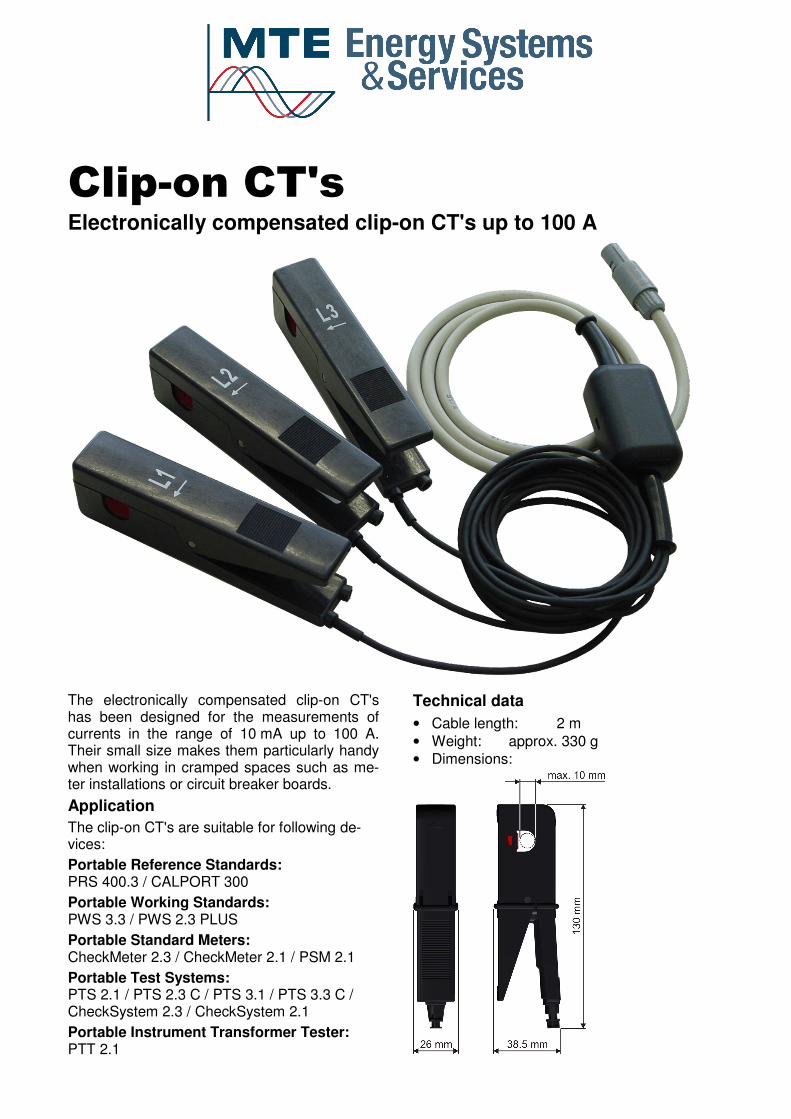
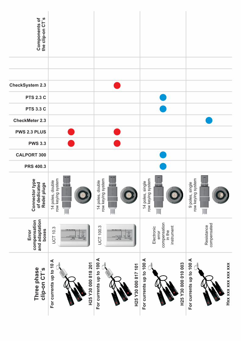
Clip-on CT's Electronically compensated clip-on CT's up to 100 A The electronically compensated clip-on CT's has been designed for the measurements of currents in the range of 10 mA up to 100 A. Their small size makes them particularly handy when working in cramped spaces such as me- ter installations or circuit breaker boards. Application The clip-on CT's are suitable for following de- vices: Portable Reference Standards: PRS 400.3 / CALPORT 300 Portable Working Standards: PWS 3.3 / PWS 2.3 PLUS Portable Standard Meters: CheckMeter 2.3 / CheckMeter 2.1 / PSM 2.1 Portable Test Systems: PTS 2.1 / PTS 2.3 C / PTS 3.1 / PTS 3.3 C / CheckSystem 2.3 / CheckSystem 2.1 Portable Instrument Transformer Tester: PTT 2.1 Technical data • Cable length: 2 m • Weight: approx. 330 g • Dimensions:
Transcript
Clip-on CT's Electronically compensated clip-on CT's up to 100 A
The electronically compensated clip-on CT's has been designed for the measurements of currents in the range of 10 mA up to 100 A. Their small size makes them particularly handy when working in cramped spaces such as me-ter installations or circuit breaker boards.
Application
The clip-on CT's are suitable for following de-vices: