36
Electronics for the Internet of Things SUMMER SCHOOL
| Date post: | 03-Aug-2015 |
| Category: |
Education |
| Upload: | alexandru-radovici |
| View: | 343 times |
| Download: | 2 times |
Electronics for the Internet of ThingsSUMMER SCHOOL
2
Outline
Electronic Signals
Electricity Equations
General Purpose Input / Output (GPIO)
Pulse Width Modulation (PWM)
Analog to Digital Converters (ADC)
Microcontrollers and Computers
Questions

3
Electronic Signals
Image from http://autosystempro.com/analog-and-digital-principles/

4
Analog and Digital We can only store digital signals
◦ Using 1 or several bits / sample
We store an array of numbers
Parameters◦ Bits per sample◦ Sampling rate
Image from http://www.centerpointaudio.com/Analog-VS-Digital.aspx

5
Bits per sample 1 bit signals sample
◦ Values LOW (0) and HIGH (1)◦ digital
n bits signals sample◦ Values 0 .. 2n-1◦ digital representation of an analog signal (analog)
Image from http://www.centerpointaudio.com/Analog-VS-Digital.aspx

6
Sampling Sensor signals are analog
Image from http://www.snotmonkey.com/work/school/405/overview.html

7
Sampling Rate The faster we sample the higher the accuracy
Nyquist Theorem◦ Sampling frequency >= 2 x maximum frequency
Voice is 0.3 .. 3.4 KHz◦ 8KHz phone
Image from http://www.jazzpoparkisto.net/audio/audio32.html
8
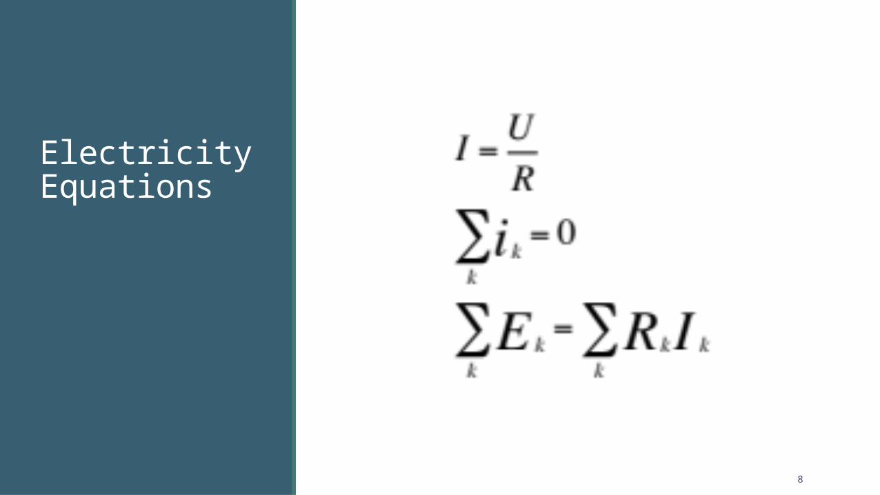
Electricity Equations

9
Ohm’s Law

10
Kirchhoff Law I

11
Kirchhoff’s Law II

12
Voltage Divider
We measure Vout

13
Voltage Divider

14
Voltage Divider

15
Voltage Divider

16
Voltage Divider

17
Voltage Divider

18
Voltage Divider
Short circuit
19
General Purpose Input / Output

20
Output and Input Digital Pins
◦ Value LOW (0) or HIGH (1)
Each pin acts like a ◦ battery (OUTPUT)◦ voltage meter (INPUT)

21
Output Pins act like a battery
◦ LOW – 0V◦ HIGH – 5V, 3.3V or 1.8V

22
Input We measure Vout
◦ It goes into the pin

23
Pulse With Modulation

24
Pulse Width We set the % of “high” cycle
◦ 0 – 0%◦ 255 – 100%
◦ Depends on the library
Implementation◦ Hardware◦ Software
Usage◦ LED dimming◦ Servo Motors

25
Analog to Digital Converters

26
Analog and Digital Converters Measure voltage
Parameters◦ Bits per sample◦ Sampling rate
For 1 bit we have …
Image from http://www.centerpointaudio.com/Analog-VS-Digital.aspx

27
Analog and Digital Converters Measure voltage
Parameters◦ Bits per sample◦ Sampling rate
For 1 bit we have …◦ GPIO Input
Image from http://www.centerpointaudio.com/Analog-VS-Digital.aspx

28
Analog and Digital Converters Measure voltage
Parameters◦ Bits per sample◦ Sampling rate
For 1 bit we have …◦ GPIO Input
Image from http://www.centerpointaudio.com/Analog-VS-Digital.aspx

29
Analog and Digital Converters Measure voltage
Parameters◦ Bits per sample◦ Sampling rate
For 1 bit we have …◦ GPIO Input
For n bits we have …
Image from http://www.centerpointaudio.com/Analog-VS-Digital.aspx

30
Analog and Digital Converters Measure voltage
Parameters◦ Bits per sample◦ Sampling rate
For 1 bit we have …◦ GPIO Input
For n bits we have …◦ 0 – 2n-1
Image from http://www.centerpointaudio.com/Analog-VS-Digital.aspx

31
Analog and Digital Converters One ADC
Multiplexed◦ Reads for A0◦ Reads for A1◦ Reads for A2◦ Reads for A3…
Image from http://www.centerpointaudio.com/Analog-VS-Digital.aspx

32
Microcontrollers and Computers

Microcontrollers and Computers
Simple systems
Control hardware
Low speeds
Small memory
GPIO
PWM
ADC
Run single software
Full CPUs
High speeds
Large memory
GPIO
Run OS

Microcontrollers and computers
Firmware Software

Intel® Edison
Firmware (will be available) Software

36
Questions?


