12
AE655000E Frederiksen Scientific A/S Tel. +45 7524 4966 [email protected] Viaduktvej 35 · DK-6870 Ølgod Fax +45 7524 6282 www.frederiksen.eu ELECTRONICS IN DAILY LIFE

AE655000E
Frederiksen Scientific A/S Tel. +45 7524 4966 [email protected]
Viaduktvej 35 · DK-6870 Ølgod Fax +45 7524 6282 www.frederiksen.eu
ELECTRONICS IN DAILY LIFE

Students’ lab manual for 655000 Breadboard electronics set, 6 groups Version 2017-07-13 / HS
© Frederiksen Scientific A/S
Overview of components
Name Number Schematics Breadboard
drawing
Battery 1
Resistor
4 of 1 kΩ
4 of 4,7 kΩ
4 of 10 kΩ
4 of 100 kΩ
LED 4
Transistor 4
Light dependent resistor 1
Capacitor
2 of 10 µF
2 of 100 µF
1 of 1000 µF
Switch 2
Relay 1
Buzzer 1
Potentiometer 1
Temperature sensitive resistor 1
10 cm mini cable
0,8 mm male – male
1 yellow
1 blue
20 cm mini cable
0,8 mm male – male
1 red
1 black
Adapter cable
0,8 mm female – 4 mm female
1 red
1 black
Battery clip 1
Breadboard 1

1 – The Light emitting diode (LED)
How do you make an LED shine weakly, resp. brightly?
a)
Build the circuit so that the current from the battery runs
through an LED (LED1) and a 1 kΩ resistor (R1).
(The short blue lead on the drawing makes it easy to change
the circuit in the next paragraph.)
The longest lead on the LED connects to plus. You will
notice also that the rim at the base of the LED is missing
next to the other leg. On the breadboard drawing both
features are marked.
An LED must always be in a series circuit with a resistor –
otherwise a large current will flow and the diode will be
damaged.
Now, try to exchange the resistor R1 with one of 10 kΩ.
What happens to the light?
Now, try to exchange R1 with a resistor of 100 kΩ.
What happens to the light? (You may need to shade the LED
with your hands or turn off the light.)
Write down your observations!
b)
Change the circuit to let the current go through an ammeter
with a range that lets you measure down to 0.01 A
Start with a 1 kΩ resistor and write down the size of the
current.
Change to a 10 kΩ resistor and write down the size of the
current.
Do the same with a 100 kΩ resistor.
What happens to the current when the resistance
increases?
What is the relationship between the current and the
brightness of the LED?
c)
A diode is also called a rectifier.
Remove the LED and re-insert it backwards (i.e. with
the longest lead away from plus).
How large is the current now?
Is the LED lit?

2 – The transistor
How can you make a tiny current control a much larger one?
– We use the transistor as a switch.
The transistor has three connections called base, emitter
and collector. To the right you can see the schematics
symbol and drawings from below (one) and above (three)
– with the leads bend in the right direction for experiments
with the breadboard.
a)
Build the transistor circuit as shown. Bend the leads of the
transistor as indicated to make it fit. Be careful not to
confuse the leads!
On the ammeter, select a range capable of measuring down
to 0.01 A.
If everything is OK, the LED should light up!
In case it doesn’t, go through the connections carefully:
Both the transistor and the LED must be oriented correctly.
The ammeter must be turned un – and must be set for
measuring DC current.
In this setup, the ammeter measures the current flowing
into the base of the transistor.
How large is the base current? – Write down.
b)
Swap the ammeter and the blue wire in order to change the
circuit as shown.
Now, the ammeter measures the current flowing into the
collector of the transistor.
How large is the collector current? – Write down.
Is the base current or the collector current largest?
How many times larger?
3 – Light sensor
How does a photocell work?
a)
The photocell we use is called an LDR – a Light Dependent
Resistor.
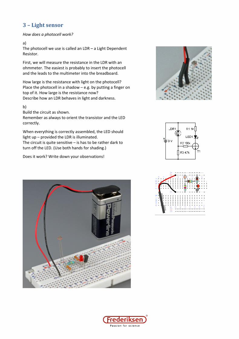
First, we will measure the resistance in the LDR with an
ohmmeter. The easiest is probably to insert the photocell
and the leads to the multimeter into the breadboard.
How large is the resistance with light on the photocell?
Place the photocell in a shadow – e.g. by putting a finger on
top of it. How large is the resistance now?
Describe how an LDR behaves in light and darkness.
b)
Build the circuit as shown.
Remember as always to orient the transistor and the LED
correctly.
When everything is correctly assembled, the LED should
light up – provided the LDR is illuminated.
The circuit is quite sensitive – is has to be rather dark to
turn off the LED. (Use both hands for shading.)
Does it work? Write down your observations!

4 –The capacitor
How can a capacitor be used for creating a delay? We
investigate charging and discharging of a capacitor.
a)
The capacitance value is printed on the capacitor. The
Greek letter ”µ” is usually pronounced “mju”. The unit ”µF”
is read as “micro farad”. It is also OK to write it as “uF”. We
start with 100 µF.
Build the circuit as shown. Take care to turn the capacitor
the right way – otherwise it can be damaged. Minus is
clearly marked. And as usual, the diode must also be
oriented correctly.
When pressing the switch down, current flows – the diode
lights up. What happens when the switch is released?
Try to remove the capacitor from the circuit and compare
the behaviour. What is the difference? – Write down.
The capacitor is charged through the switch and afterwards
discharged through the resistor and the LED.
b)
Try varying the capacitance by changing the capacitor. Test
the functioning of the circuit with all three capacitor sizes.
Write down what happens when using a small (10 µF), an
intermediate (100 µF) and a large (1000 µF) capacitor.
5 – Time delay with capacitor and
transistor
How can we obtain very long delays? What is the
significance of the resistance when discharging a capacitor?
a)
We will use a transistor switch combined with a capacitor.
Build the circuit shown with the small 10 µF capacitor.
When current flows through the switch the capacitor is
charged. It is discharged through the 10 kΩ resistor (R2)
and the base of the transistor.
If everything is connected correct the LED should light up
when the switch is pressed.
What happens when releasing the button? – Write it down.
b)
Change the capacitor to the intermediate one (100 µF).
What do you expect to happen? Did it happen?

c)
Keep the 100 µF capacitor in the circuit but change the
resistor R2 from 10 kΩ to 1 kΩ.
Write down what happened to the delay time.
Change resistor R2 again – this time using a 100 kΩ resistor.
What would you expect? What happened?
Don’t forget to write down.
6 – Staircase lighting
How do you make the lighting of a stairwell stay on some
time after turning it on?
a)
Build the circuit shown.
It starts like that in the previous paragraph but a relay
control has been added.
A relay is an electrically controlled switch. Relays exist with
very high current ratings. The relay we use can, however,
only switch currents up to 1 A. When the LED turns on and
off you can hear the relay giving a faint click.
b)
Now you will use the circuit for controlling a
lamp bulb. You will need a 12 V power supply
and a 12 V / 0.25 A incandescent lamp.
Add this to the circuit as shown and adjust the
power supply to 12 V.
Press the button – is it working?
c)
Try now with another capacitor in order to
obtain a sufficiently long lighting interval. You can also try
to change the resistor that is determining the delay time
(…which one was that?)
Write down the delay times you obtain with the different
combinations of resistor and capacitor.
7 – A temperature sensor
How can the temperature control a current?
a)
We use an NTC – a temperature dependent resistor. (NTC
stands for “Negative Temperature Coefficient”).
Start by examining the NTC resistor with an ohmmeter –
like you did with the LDR in paragraph 3.
How large is the resistance at room temperature?
Try heating the NTC by holding it between two fingers.
What is the resistance at “finger temperature”?
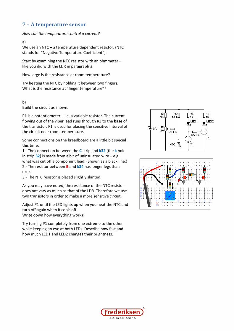
b)
Build the circuit as shown.
P1 is a potentiometer – i.e. a variable resistor. The current
flowing out of the viper lead runs through R3 to the base of
the transistor. P1 is used for placing the sensitive interval of
the circuit near room temperature.
Some connections on the breadboard are a little bit special
this time:
1 - The connection between the C strip and k32 (the k hole
in strip 32) is made from a bit of uninsulated wire – e.g.
what was cut off a component lead. (Shown as a black line.)
2 - The resistor between B and k34 has longer legs than
usual.
3 - The NTC resistor is placed slightly slanted.
As you may have noted, the resistance of the NTC resistor
does not vary as much as that of the LDR. Therefore we use
two transistors in order to make a more sensitive circuit.
Adjust P1 until the LED lights up when you heat the NTC and
turn off again when it cools off.
Write down how everything works!
Try turning P1 completely from one extreme to the other
while keeping an eye at both LEDs. Describe how fast and
how much LED1 and LED2 changes their brightness.

8 – Memory
Can an electronic circuit remember? We build a 1 bit
memory.
a)
Build a transistor switch again. – See the drawings.
Notice the blue wire that connects to either 0 V (the C strip
on the breadboard) or 9 V (the B strip).
As a start, connect the blue wire to 9 V – this should light up
the LED.
You will now use a voltmeter connected
between 0V and one of the nodes called Input
and Output on the image. There is no need for
precise readings, simply decide if the voltage
is high (more than 4 V) or low (below 4 V).
When the input is high: What is the output?
When the output is high: What is the input?
Write your observations down.
b)
The circuit is now extended with another transistor switch.
Connect the output of the first switch with the input of the
next. With a wire, connect output 2 back to input 1 (see
drawing).
In fact, the memory is finished now – but its content will be
random! Now it is time to make it remember what you
decides.
This is done by the circuitry with the two pushbutton
switches, connected by the yellow wire directly to the base
of the first transistor. The complete circuit is drawn below.
Now the circuit remembers which switch you press. Try it!
Write down what happens.

9 – LED flasher
How does a car’s hazard light work?
a)
Try to build the circuit shown.
Insert the two capacitors last – there is just room enough.
If everything has been connected correctly, you have
made an LED flasher!
b)
Which of the components do you think are important for
how fast the LEDs are flashing?
Can you change the circuit to make it flash ten times faster?
Can you make it flash ten times slower?
Remember to write down your modifications and
observations.

10 – Burglar alarm
Vi build a light sensitive burglar alarm!
a)
The circuit consists of a light sensor and a slightly modified
memory. You will also need: Black paper (approx. 5 x 7 cm),
tape, a flashlight or similar.
Build the circuit as shown. – Note the use of 10 kΩ (instead
of 100 kΩ) as base resistors in the memory (R2 and R4), and
that one of the collector resistors in the memory has been
replaced by a buzzer (R1 is missing, compared with the
paragraph “Memory”).
The light sensor connects to the memory through an LED
(LED4) – here used as a rectifier.
Take care to illuminate the LDR when you
connect the battery. In case the buzzer
turns on it should be possible to stop it with
the switch.
b)
Make a tube of black paper:
Roll it around e.g. a thick speed marker and
fix it with tape.
If you places the tube around the LDR and
shades it with your hand, the alarm
should go off.
Even if the photocell is illuminated again,
the alarm must continue to sound until
you press the button.
Bend the photocell leads and place the
tube to make the photocell “peek”
horizontally through the tube. Fix the
tube to the breadboard – see the photo.
When the light from the flashlight falls
onto the sensor, the alarm can be
stopped with the switch – but as soon as
the light beam is broken, it goes off!

11 – Thermostat
How do you control temperature? We build a
thermostat
a)
Build the circuit shown.
The thermostat consists of a temperature sensor and
a relay controller. Refer to paragraph 7 concerning
the connections to the potentiometer.
Check the circuit: When you turn the potentiometer
P1 completely up and down, you should hear the relay click.
Turn completely down to make LED2
light up. Turn slowly up until the relay
clicks (turns on) – together with LED2
turning off. You should now be able
to make the relay click again (turn off)
if you warm the NTC resistor with
your fingers. – And when it cools
down again, the relay should click
once more.
You may need to fine tune P1.
b)
The circuit is used for controlling a light bulb. You will need
a 12 V power supply and a 12 V / 0.25 A incandescent lamp.
(Not an LED bulb – we need the heat from the light bulb.)
Add this to the circuit as shown and adjust the power
supply to 12 V.
The lamp must turn off and on when the NTC is heated and
cooled down.
Place the light bulb so that it touches the NTC.
Preferably without you having to hold it there.
The lamp will blink slowly!
Write an explanation of what happens!


