Electrostatic System Installation, Checks, and Troubleshooting Customer Product Manual Part 334632A Issued 4/03 NORDSON CORPORATION AMHERST, OHIO USA For parts and technical support, call the Industrial Coating Systems Customer Support Center at (800) 433-9319 or contact your local Nordson representative. This document is subject to change without notice. Check http://emanuals.nordson.com for the latest version.
Transcript
Electrostatic System Installation,Checks, and Troubleshooting
Customer Product ManualPart 334632A
Issued 4/03
NORDSON CORPORATION AMHERST, OHIO USA
For parts and technical support, call the Industrial CoatingSystems Customer Support Center at (800) 433-9319 or
contact your local Nordson representative.
This document is subject to change without notice.Check http://emanuals.nordson.com for the latest version.
Contact UsNordson Corporation welcomes requests for information, comments, andinquiries about its products. General information about Nordson can befound on the Internet using the following address:http://www.nordson.com.Address all correspondence to:
Nordson CorporationAttn: Customer Service555 Jackson StreetAmherst, OH 44001
NoticeThis is a Nordson Corporation publication which is protected by copyright.Original copyright date 2000. No part of this document may bephotocopied, reproduced, or translated to another language without theprior written consent of Nordson Corporation. The information containedin this publication is subject to change without notice.
Trademarks
Nordson and the Nordson logo are registered trademarks of NordsonCorporation.
Freon is a registered trademark of E.I. DuPont de Nemours andCompany.
Electrostatic System Installation, Checks, and Troubleshooting 1
Part 334632A 2003 Nordson Corporation
Electrostatic System Installation,Checks, and Troubleshooting
Safety Read and follow these safety instructions. Task- and equipment-specificwarnings, cautions, and instructions are included in equipmentdocumentation where appropriate.
Make sure all equipment documentation, including these instructions, isaccessible to all persons operating or servicing equipment.
Qualified Personnel Equipment owners are responsible for making sure that Nordson equipmentis installed, operated, and serviced by qualified personnel. Qualifiedpersonnel are those employees or contractors who are trained to safelyperform their assigned tasks. They are familiar with all relevant safety rulesand regulations and are physically capable of performing their assignedtasks.
Intended Use Use of Nordson equipment in ways other than those described in thedocumentation supplied with the equipment may result in injury to personsor damage to property.
Some examples of unintended use of equipment include
using incompatible materials
making unauthorized modifications
removing or bypassing safety guards or interlocks
using incompatible or damaged parts
using unapproved auxiliary equipment
operating equipment in excess of maximum ratings
Regulations and Approvals Make sure all equipment is rated and approved for the environment in whichit is used. Any approvals obtained for Nordson equipment will be voided ifinstructions for installation, operation, and service are not followed.
All phases of equipment installation must comply with all federal, state, andlocal codes.
Electrostatic System Installation, Checks, and Troubleshooting2
Part 334632A 2003 Nordson Corporation
Personal Safety To prevent injury follow these instructions.
Do not operate or service equipment unless you are qualified.
Do not operate equipment unless safety guards, doors, or covers areintact and automatic interlocks are operating properly. Do not bypass ordisarm any safety devices.
Keep clear of moving equipment. Before adjusting or servicing anymoving equipment, shut off the power supply and wait until theequipment comes to a complete stop. Lock out power and secure theequipment to prevent unexpected movement.
Relieve (bleed off) hydraulic and pneumatic pressure before adjusting orservicing pressurized systems or components. Disconnect, lock out,and tag switches before servicing electrical equipment.
Obtain and read Material Safety Data Sheets (MSDS) for all materialsused. Follow the manufacturer’s instructions for safe handling and useof materials, and use recommended personal protection devices.
To prevent injury, be aware of less-obvious dangers in the workplacethat often cannot be completely eliminated, such as hot surfaces, sharpedges, energized electrical circuits, and moving parts that cannot beenclosed or otherwise guarded for practical reasons.
Fire Safety To avoid a fire or explosion, follow these instructions.
Do not smoke, weld, grind, or use open flames where flammablematerials are being used or stored.
Provide adequate ventilation to prevent dangerous concentrations ofvolatile materials or vapors. Refer to local codes or your material MSDSfor guidance.
Do not disconnect live electrical circuits while working with flammablematerials. Shut off power at a disconnect switch first to preventsparking.
Know where emergency stop buttons, shutoff valves, and fireextinguishers are located. If a fire starts in a spray booth, immediatelyshut off the spray system and exhaust fans.
Clean, maintain, test, and repair equipment according to the instructionsin your equipment documentation.
Use only replacement parts that are designed for use with originalequipment. Contact your Nordson representative for parts informationand advice.
Electrostatic System Installation, Checks, and Troubleshooting 3
Part 334632A 2003 Nordson Corporation
Grounding
WARNING: Operating faulty electrostatic equipment is hazardous and cancause electrocution, fire, or explosion. Make resistance checks part of yourperiodic maintenance program. If you receive even a slight electrical shockor notice static sparking or arcing, shut down all electrical or electrostaticequipment immediately. Do not restart the equipment until the problem hasbeen identified and corrected.
All work conducted inside the spray booth or within 1 m (3 ft) of boothopenings is considered within a Class 2, Division 1 or 2 Hazardous locationand must comply with NFPA 33, NFPA 70 (NEC articles 500, 502, and 516),and NFPA 77, latest conditions.
All electrically conductive objects in the spray areas shall be electricallyconnected to ground with a resistance of not more than 1 megohm asmeasured with an instrument that applies at least 500 volts to the circuitbeing evaluated.
Equipment to be grounded includes, but is not limited to, the floor of thespray area, operator platforms, hoppers, photoeye supports, andblow-off nozzles. Personnel working in the spray area must begrounded.
There is a possible ignition potential from the charged human body.Personnel standing on a painted surface, such as an operator platform,or wearing non-conductive shoes, are not grounded. Personnel mustwear shoes with conductive soles or use a ground strap to maintain aconnection to ground when working with or around electrostaticequipment.
Operators must maintain skin-to-handle contact between their hand andthe gun handle to prevent shocks while operating manual electrostaticspray guns. If gloves must be worn, cut away the palm or fingers, wearelectrically conductive gloves, or wear a grounding strap connected tothe gun handle or other true earth ground.
Shut off electrostatic power supplies and ground gun electrodes beforemaking adjustments or cleaning powder spray guns.
Connect all disconnected equipment, ground cables, and wires afterservicing equipment.
Action in the Event of a Malfunction If a system or any equipment in a system malfunctions, shut off the systemimmediately and perform the following steps:
Disconnect and lock out electrical power. Close pneumatic shutoffvalves and relieve pressures.
Identify the reason for the malfunction and correct it before restarting theequipment.
Disposal Dispose of equipment and materials used in operation and servicingaccording to local codes.
Electrostatic System Installation, Checks, and Troubleshooting4
Part 334632A 2003 Nordson Corporation
Safety Label
Table 1 Safety Label
Item Part Description
244644
WARNING: The following procedures MUST be followed when workingwith this electrostatic spray equipment. Failure to follow theseinstructions may result in a fire and/or serious personal injury. Displaythis warning on the spray booth.
1. NO SMOKING. Keep open flames, hot surfaces, and sparks fromtorches or grinding away from booth.
2. Turn the electrostatic power unit off when the spray gun is not inuse.
3. Shut down immediately in event of fire.
4. Maintain ground circuit on all conductive objects below 1 megohm toprevent sparking. (ANSI/NFPA 33, Chapter 9, or local codes)
5. Shut down operation and correct grounds if sparking occurs
6. Install fixed fire suppression system in accordance withANSI/NFPA 33, Chapter 7 (or local codes), before operating withcombustible powder.
7. Install automatic flame detectors in accordance with ANSI/NFPA 33,Chapter 7 (or local codes), before operating automatic guns
8. Examine all equipment at the beginning of each work period andrepair or replace any damaged, loose, or missing parts.
9. Before cleaning or performing any maintenance on the electrostaticspray gun, turn off the power unit and ground the nozzle. Maintainelectrostatic spray equipment in accordance with instruction manual.Do not deviate. Do not substitute parts from other manufacturers.
10. Operator must be grounded to prevent shocks from static electricity.Floor surface must be conductive. Footwear and gloves must bestatic dissipative in accordance with ANSI Z41-1991 (or localcodes).
11. Air velocity through all booth openings must meet local requirementsand contain powder within the booth. If powder escapes from thebooth, shut down operation and correct the malfunction.
12. Powder may be toxic or be a nuisance dust hazard. Refer tosupplier’s MSDS. If exposed to dust during operation, maintenance,or clean up, operators must use appropriate personal protectiveequipment.
13. Do not use compressed air or organic solvents for removal ofpowder from skin or clothing. Do use soap and water. Wash handsbefore eating or smoking.
14. Guns, feeders, booths, etc., may be cleaned with clean dry air at1.7 bar (25 psig).
If you have any questions concerning this electrostatic spray equipment, call(440) 988-9411,and ask to speak with the Powder Systems Group Technical ServiceDepartment.
Electrostatic System Installation, Checks, and Troubleshooting 5
Part 334632A 2003 Nordson Corporation
Description An electrostatic system requires installation, checks, and troubleshooting tomake sure that the operator, and all components and conductive materialswithin the spray area are connected to an earth ground. The checks arealso necessary to analyze problems in conventional electrostatic systems.
Electrostatic CableSee Figure 1. The grounded sheath (2) is a braided wire, and acts as theouter conductor of the co-axial cable. The grounded sheath is attached tothe stationary section of the connecting nut (3).
The high dielectric insulating material (4) separates the outer conductorfrom the high-voltage inner conductor (5). The high voltage inner conductoris a system of resistors and conductors that terminates at each end with abrass tip (6).
1401239A
3
2
1
45
6
7
Figure 1 Cut-Away View of an Electrostatic Cable
1. Outer cover2. Grounded sheath3. Connecting nut4. High dielectric insulating material
5. High voltage inner conductor6. Brass tip7. Control wires (if used)
Electrostatic System Installation, Checks, and Troubleshooting6
Part 334632A 2003 Nordson Corporation
InstallationWARNING: Allow only qualified personnel to perform the following tasks.Follow the safety instructions in this document and all other relateddocumentation.
Use the following tables to install the electrostatic cable and the gunextension resistor.
Electrostatic Cable Installation
For NPE-CC8H For NPE-CC2
NOTE: Do not use oil
1. Use a clean, dry cloth to wipe off any contamination from the power unit end of the electrostatic cable.
NOTE: If contamination does not readily wipe off, slightly dampen a cloth with isopropyl/alcohol toremove oily soil. Be sure that the cable is thoroughly dried before assembly.
2. Cut off the tips of the high voltage insulating oilcontainers. Pour 11/2 containers into thehigh-voltage well of the multiplier.
2. Insert the tip of the 10-cc dielectric greaseapplicator into the high-voltage well of themultiplier, and empty the contents into the well.high-voltage well of the multiplier.
NOTE: High-voltage insulating oil contains noPCB.
multiplier, and empty the contents into the well.
3. Slowly insert the high-voltage cable into thewell, wiping any oil as it overflows the well.
3. Insert the high-voltage cable into the well.
4. Use the nut on the cable to secure and attachthe cable to the strain relief on the side of thecabinet.
4. Use the nut on the cable to secure the cable.
5. Use a clean, dry cloth to wipe clean the gun end of the electrostatic cable, and install the cable into thegun. Tighten the connecting nut.
NOTE: For more information about spray gun installation, refer to the spray gun manual.
Electrostatic System Installation, Checks, and Troubleshooting 7
Part 334632A 2003 Nordson Corporation
Gun Extension Resistor with One Spacer RingNOTE: Dielectric grease is an insulating material. Place it around contactpoints in a high-voltage system to eliminate corona discharge or arcing,which will cause premature failure of adjoining parts.
NOTE: Before working on the resistor, make sure that your hands are cleanand have no residual paint, solvent, or oil on them.
Step Illustration
1. Coat the resistor with 1/3 of thegrease contained in thesyringe. Spread the greaseover the resistor with yourfingers, making sure theresistor is completely covered.
1401240A
1/3
2. Inject all but 1/4 cc of theremaining grease into thespring so that the spring andscrew are totally embedded ingrease.
1401241A
ALL BUT1/4cc
3. Place the resistor into theinsulating tube, spring end first.
1401242A
4. Inject the remaining 1/4 cc ofgrease into the insulating tubeon the opposite end of theresistor from the spring.
1401243A
5. Install the tube and resistor intothe gun extension so that thespring end of the resistor facestoward the gun body or handle.
1401244A
Front of gun (into extension)
Rear of gun (toward body or handle)
Electrostatic System Installation, Checks, and Troubleshooting8
Part 334632A 2003 Nordson Corporation
System Checks WARNING: Allow only qualified personnel to perform the following tasks.Follow the safety instructions in this document and all other relateddocumentation.
WARNING: The circuit values must be established and maintained, withinspecifications, for both fire safety and static shock avoidance. Usingelectrostatic equipment that does not meet specifications could result inserious injury and property damage.
Why Complete System Checks? NOTE: Use a 500 V or 1000 V megohmmeter to compete the systemchecks.
To make sure the operator, spray gun, power unit, cable, and allconductive materials within the spray area are connect to earth ground.
Proper grounding is essential for efficient operation and to prevent abuildup and subsequent discharge of an electrostatic charge whichcould ignite combustible material within the spray area.
To make sure the electrostatic equipment has and maintains the properresistance values which are important to maintain the equipment withindesigned current outputs.
The resistance values may vary over a period of time due to conditionssuch as a buildup of residue in the spray area which results indegradation of electrical components that have been exposed to highvoltages.
Electrostatic System Installation, Checks, and Troubleshooting 9
Part 334632A 2003 Nordson Corporation
Installation Checks Installation checks verify correct electrical resistances and ensure propergrounding connections. Make these checks when installing new equipmentor replacing components within an existing system.
NPE-1A $ 1M: 275 MΩ 10%1 For guns with 4 m (13 ft) cable, subtract 100 MΩ. For guns with alance extension, add 20 MΩ.
Reason for Check:Determines total resistance of gun and cable
Corrective Action:1401245A
If the readings are not within the minimum or maximum specifications:
1. Remove the cable from the gun and perform cable checks 8through 11.
2. Remove the resistor from the gun and check the resistance.
3. Clean and inspect the gun extension.
2. Electrode at tip of gunto gun handle or body(with cable removedfrom power unit)
Required Readings:Infinity Ω
p )
Reason for Check:Makes sure that no electrical path exists within gun which will bypass allor part of electrostatic charge to ground
1401246A
Corrective Action:Disassemble and clean the gun. Replace parts as necessary.
3. Handle or body of gunto earth ground (withcable installed in powerunit)
Required Readings:0 Ω
Reason for Check:Makes sure guns, cable, and power unit provide path to ground; ensures operator grounding
1401247A
POWER UNIT
Corrective Action:If the readings are greater than 0 Ω, check all of the connections.
Continued...
Electrostatic System Installation, Checks, and Troubleshooting10
Part 334632A 2003 Nordson Corporation
Installation Checks (contd)
Installation Checks
4. Measure from pin to pinat connecting nut
Required Readings:NPE-2M: 0 Ω: trigger depressedInfinity Ω: trigger released
Reason for Check:Confirms operation of switch in gun handle that turns power unit highvoltage on and off
1401248A
Corrective Action:Replace the switch if it is not operating properly.
5. Triggering for NPE-1A,1M, and 2A guns fromcontrol console
Corrective Action:Refer to the control console manual for details.
6. End to end of gunresistor
Required Readings:NPE-2A & 2M: 175 MΩ 10%
NPE-1A & 1M: 75 MΩ 10%
Reason for Check:Determines resistance of current limiting resistor
1401249A
Corrective Action:If the readings are not within the specified range, replace the resistor.
7. Connecting nut on oneend of cable toconnecting nut on otherend of cable
Required Readings:0 Ω
Reason for Check:Ensures that sheath of cable provides a path to ground from gun topower unit
1401250A
Corrective Action:If the readings are greater than 0 Ω, look for a break in the sheath or apoor connection at the connecting nut.
Continued...
Electrostatic System Installation, Checks, and Troubleshooting 11
Part 334632A 2003 Nordson Corporation
Installation Checks
8. Connecting nut on oneend of cable to centerconductor (brass tip)
Required Readings:Infinity Ω
Reason for Check:Checks for burn-through in cable
1401251A
Corrective Action:If the cable has a path between the center conductor and the sheath,replace the cable.
9. Brass tip at gun end ofhigh voltage conductorto brass tip at other endof high voltageconductor
Required Readings:Standard cable: 200 MΩ 10%
1.2 m (4 ft) powder cable: 100 MΩ 10%
Reason for Check:Determines proper current limiting resistance in cable
1401252A
Corrective Action:If the readings are not within the specified range, replace the cable.
10. Cable control wires forairless and somepowder hand guns
1A
Required Readings:1 to 1A—0 Ω2 to 2A—0 Ω1 to 2—Infinity Ω1 to connecting nut—Infinity Ω2 to connecting nut—Infinity Ω
1 21A2A Reason for Check:
Checks continuity of wires and ensures isolation between control wiresand grounded sheath
1401253A
Corrective Action:Look for breaks in the control wire or missing insulation. Repair the wireif possible.NOTE: Some cables come with control wires installed but not used. These unused control wires require no checks.
Continued...
Electrostatic System Installation, Checks, and Troubleshooting12
Part 334632A 2003 Nordson Corporation
Installation Checks (contd)
Installation Checks11. Power unit well housing
to earth groundRequired Readings:0 Ω
Reason for Check:Ensures that power supply is connected to earth ground
1401254A
POWER UNIT Corrective Action:If the reading is greater than 0 Ω, check the power unit grounding device.
12. Cable connecting nut toearth ground
Required Reading:0 Ω
Reason for Check:Insures that cable makes good connection at power unit
Corrective Action:
POWER UNIT 1. Check the cable nut tightness.
1401255A 2. Check for good connection with the cable sheath.
13. Bare hand of operatorto earth ground whilestanding and walking
Required Reading:Less than 50 MΩ (recommended)
standing and walkingon usual work surfacein spray area
Reason For Check:Ensures that personnel in spray booth do not accumulate static chargeon the their bodies, which presents fire hazard and shock hazard
Corrective Action:
1. Check shoes (soles must be made of conductive materials).
2. Provide additional grounding devices (for example, shoe straps or awrist strap).
1401256A3. Check if the floor of the booth is ungrounded or insulated by an
accumulation of residue. Correct as appropriate.
14. Fluid supply (if withinspray) area to earthground
Required Reading:0 Ω
Reason for Check:Makes sure all components within spray area are at ground potential toprevent static buildup
1401257A
Corrective Action:Add additional grounding devices if necessary.
Continued...
Electrostatic System Installation, Checks, and Troubleshooting 13
Part 334632A 2003 Nordson Corporation
Installation Checks
15. Part to be coated toearth ground
Required Readings:Ideal: 0 Ω
Acceptable: 200 to 300 Ω
Corrective action necessary: 1 MΩ
Reason for Check:Provides path from part to ground, preventing part from building upelectrostatic charge
1401258A Corrective Action:Clean the hooks, hangers and conveyor.
16. Floor of booth to earthground
Required Readings:Metal floors: 0 Ω
Floors constructed of other material: 50 MΩReason for Check:Ensures that operator has path to ground to prevent accumulation ofcharge on operator’s body
1401259A
Corrective Action:Clean the grating or make a provision for the operator to be grounded.NOTE: For booth floors constructed of materials other than metal, it maybe necessary to puddle a small amount of tap water on the floor toprovide an electrical connection for the meter probe.
Electrostatic System Installation, Checks, and Troubleshooting14
Part 334632A 2003 Nordson Corporation
Periodic Checks WARNING: If any checks provide readings which are not withinspecifications, a potential personnel and fire hazard exists. Do not operatethe equipment until you take corrective action.
WARNING: Before removing an electrostatic cable from an operatingpower unit, turn off the power unit and wait at least three minutes to allowany residual voltage in the cable to bleed off.
WARNING: Once an electrostatic cable is removed from an operatingpower unit, touch the brass tip of the cable end to earth ground to removeany residual voltage in the cable before attempting an electrical resistancemeasurement.
WARNING: When checking kV on positive kV CC8 and CC2 power units,contact your Nordson Corporation representative for proper kV analysisprocedures.
Periodic checks maintain proper grounding and resistance values. Ifresistance values are out of specification, refer to the systemtroubleshooting procedures for corrective actions.
NPE-1A $ 1M: 275 MΩ 10%1 For guns with 4 m (13 ft) cable, subtract 100 MΩ. For guns with alance extension, add 20 MΩ.
Reason for Check:Determines total resistance of gun and cable
Corrective Action:1401245A
If the readings are not within the minimum or maximum specifications:
1. Remove the cable from the gun and perform installation checks 8through 11.
2. Remove the resistor from the gun and check the resistance.
3. Clean and inspect the gun extension.
2. Electrode at tip of gunto gun handle or body(with cable removedfrom power unit)
Required Readings:Infinity Ω
p )
Reason for Check:Makes sure that no electrical path exists within gun which will bypass allor part of electrostatic charge to ground
1401246A
Corrective Action:Disassemble and clean the gun. Replace parts as necessary.
Continued...
Electrostatic System Installation, Checks, and Troubleshooting 15
Part 334632A 2003 Nordson Corporation
Periodic Checks
3. Handle or body of gunto earth ground (withcable installed in powerunit)
Required Readings:0 Ω
Reason for Check:Makes sure guns, cable, and power unit provide path to ground; ensuresoperator grounding
1401247A
POWER UNIT
Corrective Action:If the readings are greater than 0 Ω, check all of the connections.
4. Bare hand of operatorto earth ground whilestanding and walking
Required Reading:Less than 50 MΩ (recommended)
standing and walkingon usual work surfacein spray area
Reason For Check:Ensures that personnel in spray booth do not accumulate static chargeon the their bodies, which presents fire hazard and shock hazard
Corrective Action:
1. Check shoes (soles must be made of conductive materials).
2. Provide additional grounding devices (for example, shoe straps or awrist strap).
1401256A
3. Check if the floor of the booth is ungrounded or insulated by anaccumulation of residue. Correct as appropriate.
5. Fluid supply (if withinspray) area to earthground
Required Reading:0 Ω
Reason for Check:Makes sure all components within spray area are at ground potential toprevent static buildup
1401257A
Corrective Action:Add additional grounding devices if necessary.
Continued...
Electrostatic System Installation, Checks, and Troubleshooting16
Part 334632A 2003 Nordson Corporation
Periodic Checks (contd)
Periodic Checks
6. Part to be coated toearth ground
Required Readings:Ideal: 0 Ω
Acceptable: 200 to 300 Ω
Corrective action necessary: 1 MΩ
Reason for Check:Provides path from part to ground, preventing part from building upelectrostatic charge
1401258A Corrective Action:Clean the hooks, hangers and conveyor.
7. Floor of booth to earthground
Required Readings:Metal floors: 0 Ω
Floors constructed of other material: 50 MΩ
Reason for Check:Ensures that operator has path to ground to prevent accumulation ofcharge on operator’s body
1401259A
Corrective Action:Clean the grating or make a provision for the operator to be grounded.NOTE: For booth floors constructed of materials other than metal, it maybe necessary to puddle a small amount of tap water on the floor toprovide an electrical connection for the meter probe.
Troubleshooting WARNING: Allow only qualified personnel to perform the following tasks.Follow the safety instructions in this document and all other relateddocumentation.
This section contains troubleshooting instructions and specifications. Theseprocedures cover only the most common problems that you may encounter.If you cannot solve the problem with the information given here, contactyour local Nordson Corporation representative for help.
Troubleshooting Flow Diagram See Figure 2. The diagram is a step-by-step guide to solving problems inelectrostatic systems. Each check (enclosed by a rectangle) is followed bya decision block (enclosed by a diamond). The number inside the diamondcorresponds to the Troubleshooting Instructions and Specifications Chart onpages 19-21.
Electrostatic System Installation, Checks, and Troubleshooting 17
Part 334632A 2003 Nordson Corporation
NOTE: Before attempting a check, refer to the instructions andspecifications for your specific equipment.
1401260A
Check kV at electrode
Overall resistance may becorrect, but gun extensionair or fluid passages may beshorted to body or handle
Check kV at power unit well
Check resistance of part to
Check formulation of coatingmaterial
Clean conveyor, hooks, and truck
Troubleshoot power unit or
(see power unit manual)
Measure total resistance of
Measure kV at tip of cable(with cable removed from the gun)
Measure resistance of cable
Replace cable
Replace resistor
Check control wires(if used)
Replace cable
Clean power unit well and cable ends using Freon TF
Clean extension orreplace as necessary
Check gun extension for shorted air or fluid passages
Inspect insulating tube forcarbon tracking
Replace as necessary
If washer is insulated with coating material replace washer
Remove resistor from gun
1 2
3
4
5
6
7
8
9
10
11
Inspect conductive washer
OK
Low / No Output
Low / High
Open
High
Shorted
OK
OK
OK
OK
OK
OK
Low /No Output
Low / High
Low / High
Low / High
NOTE: After reassembly, repeat to assure proper contact between components.4
of gun
gun and cable
be coated to earth ground
trigger switch
and measure resistance
in the gun extension (if used)
Figure 2 Troubleshooting Flow Diagram
Electrostatic System Installation, Checks, and Troubleshooting18
Part 334632A 2003 Nordson Corporation
Troubleshooting Instructions and Specifications Chart Electrostatic spraying systems, if not properly maintained and operated, aresubject to the possibility of an electrical discharge. Observe the followingsafety notes to protect both personnel and equipment.
NOTE: Troubleshooting electrostatics requires the use of both a Nordsonhandheld kV meter and megohmmeter. For more information, refer to themanuals supplied with the kV meter or megohmmeter.
WARNING: Nordson electrostatic equipment will not produce enoughcurrent to cause physical injury. Accidental contact with the electrostaticcharge may cause a shock similar to that experienced by touching adoorknob after walking across a rug. This static shock may startle theoperator, causing a secondary reaction such as a fall.
WARNING: If the equipment or any component is not within specifications,do not operate the equipment until you take corrective action.
WARNING: Before removing an electrostatic cable from an operatingpower unit, turn off the power unit and wait at least three minutes to allowany residual voltage in the cable to bleed off.
WARNING: Once an electrostatic cable is removed from an operatingpower unit, touch the brass tip of the cable end to earth ground. This actionremoves any residual voltage in the cable before attempting an electricalresistance measurement.
WARNING: When checking kV on positive kV CC8 and CC2 power units,contact your Nordson Corporation representative for proper kV analysisprocedures.
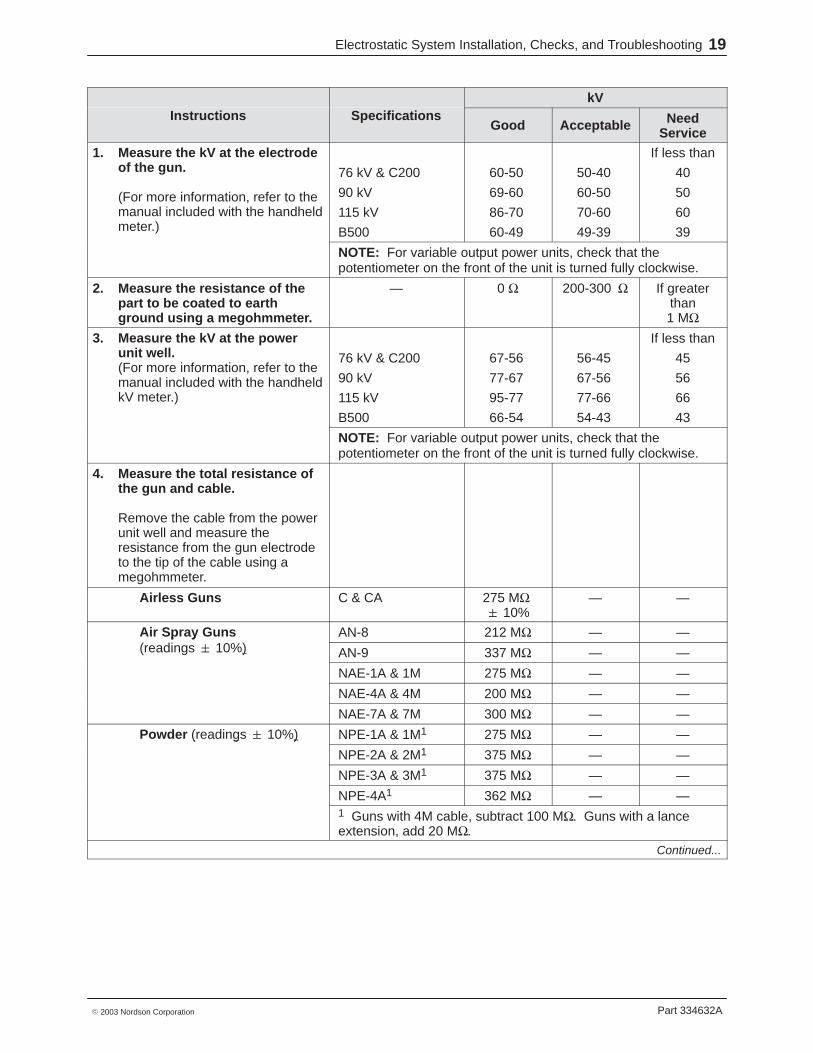
Electrostatic System Installation, Checks, and Troubleshooting 19
Part 334632A 2003 Nordson Corporation
kVInstructions Specifications
Good Acceptable NeedService
1. Measure the kV at the electrodeof the gun.
(For more information, refer to themanual included with the handheldmeter.)
76 kV & C200
90 kV
115 kV
B500
60-50
69-60
86-70
60-49
50-40
60-50
70-60
49-39
If less than
40
50
60
39
NOTE: For variable output power units, check that thepotentiometer on the front of the unit is turned fully clockwise.
2. Measure the resistance of thepart to be coated to earthground using a megohmmeter.
— 0 Ω 200-300 Ω If greaterthan1 MΩ
3. Measure the kV at the powerunit well.(For more information, refer to themanual included with the handheldkV meter.)
76 kV & C200
90 kV
115 kV
B500
67-56
77-67
95-77
66-54
56-45
67-56
77-66
54-43
If less than
45
56
66
43
NOTE: For variable output power units, check that thepotentiometer on the front of the unit is turned fully clockwise.
4. Measure the total resistance ofthe gun and cable.
Remove the cable from the powerunit well and measure theresistance from the gun electrodeto the tip of the cable using amegohmmeter.
NPE-4A1 362 MΩ — —1 Guns with 4M cable, subtract 100 MΩ. Guns with a lanceextension, add 20 MΩ.
Continued...
Electrostatic System Installation, Checks, and Troubleshooting20
Part 334632A 2003 Nordson Corporation
Troubleshooting Instructions and Specifications Chart (contd)
kVInstructions Specifications
Good Acceptable NeedService
5. Remove the cable from the gun.
Reinstall the other end of the cableinto the power unit and read thekV at the tip of the cable.
76 kV & C200
90 kV
115 kV
B500
62-52
72-63
89-72
61-50
52-42
63-53
72-62
50-40
If less than
42
53
62
40
NOTE: For variable output power units, check that thepotentiometer on the front of the unit is turned fully clockwise.
6. Remove the resistor from thegun extension.
Use a megohmmeter to readacross the resistor.
Airless Guns All Guns 75 MΩ 10%
— —
Air spray guns (readings 10%)
AN-8needle/electrodemolded resistor
12 MΩ — —
AN-9needle/electrodemolded resistor
12 MΩ — —
AN-9needle/electrodeextension resistor
126 MΩ — —
NAE-1A & 1M 75 MΩ — —
NAE-4A & 4M (no resistor) — —
NAE-7A & 7Mresistor potted inprobe
100 MΩ — —
Powder (readings 10%) NPE-1A & 1M 75 MΩ — —( g )
NPE-2A & 2M 175 MΩ — —
NPE-3A & 3M 175 MΩ — —
NPE-4A tuberesistor
150 MΩ — —
NPE-4A smallresistor withterminal
12 MΩ — —
NPE-4A lanceextension resistor
20 MΩ — —
Continued...
Electrostatic System Installation, Checks, and Troubleshooting 21
Part 334632A 2003 Nordson Corporation
Instructions Specifications kVp
Good Acceptable NeedService
7. Remove the cable from both thepower unit and the gun.
Standard cable 200 MΩ 10%
— —
Measure the cable resistance frombrass tip to brass tip using amegohmmeter.
4 m (13 ft) powdercable
100 MΩ 10%
— —
Measure resistance from the tip ofthe cable to the connecting nut(stationary section) to detect aburn-through of the cable to thesheath. A dielectric burn-throughprovides a path to ground for thehigh voltage.
— Infinity Ω — —
8. Measure the resistance fromone connecting nut to the otherconnecting nut on thestationary section of the cable.
This measurement detects anopen in the sheath whichinterrupts the path to groundthrough the cable.
— 0 Ω — —
9. On some manual powder orairless guns, remove the cable
Wire 1 to connecting nut
Infinity Ω — —a ess g s, e o e e cab efrom both the power unit andthe gun.
Wire 2 to connecting nut
Infinity Ω — —
Measure the resistance of the Wire 1 to wire 2 Infinity Ω — —Measure the resistance of thecontrol wires to ensure that the
i h ti it tWire 1 end to end 1 Infinity Ω — —
wires have continuity, are notshorted together and are not
Wire 2 end to end 1 0 Ω — —shorted together, and are notshorted to the sheath. 0 Ω — —shorted to the sheath.
1 One end is at the pins of the power unit connecting nut.
NOTE: Some electrostatic cables come with control wiresinstalled but not used. These cable do not require checks.
NOTE: Wire control problems are indicated by the lack of kV atthe tip of the gun. Wire control problems may also be indicatedby an intermittent high voltage on a manual gun as the gun ismoved.
10. With the cable removed fromthe power unit, measure from
— Infinity Ω — —the power unit, measure fromthe handle or body to theelectrode of the gun using amegohmmeter.
NOTE: Any reading other than infinity indicates a path forvoltage through the extension to the grounded body or handle.
Electrostatic System Installation, Checks, and Troubleshooting22