Page 1
8/7/2019 Elements of Transit Design (Post 1999)
http://slidepdf.com/reader/full/elements-of-transit-design-post-1999 1/49
'.. 1.0. .
t l l Z ) J i 1 ~ ~ \ Q A \ \ ~ f ' r ~ , ~ t ~ t 4
INTROIJUCT ION
THE PURPOSE OF THIS COCUMENT IS TO PROVIDE ARCHITECTURAL AND
ENGINEERING CONSULTING FIRMS SELECTED BY TRANSIT PROPERTIES
WITH ESSENTIAL BACKGROUND INFORMATION ON DAILY BUS OPERATIONS
AND MAINTENANCE ACTIVITIES AS THEY RELATE TO THE DESIGN OF
SATELLITE BUS MAINTENANCE FACILITIES· IT ALSO INClIJOES BASIC
DESIGN CRITERIA AND PROTOTYPICAL LAYOUTS THAT CAN BE USED TO
DEVELOP FUNCTIONAL SPACE ALLOCATION PROGRAMS FOR BUS
MA I NTENANCE FAC III TI ES DES IGNED TO ACCOMMODATE UP TO 200 BUSES·
IT SHOULD BE UNDERSTOOD THAT THIS IS A PLANNING DOCUMENT - A
GUIDE FOR THE DESIGN PROCESS WRITTEN TO PROMOTE FURTHER INQUIRY
AND .llill TO BE REGARDED AS A COOKBOOK.
ARCHITECTURAL/ENGINEERING FIRMS SHOULD BECOM: AS FULLY INFORMED
ASPOSSIBLE
OF THE RAPID CHANGES TAKING PLACE IN THE TRANSITINDUSTRY AND PROCEED WITH A FACILITY DESIGN THAT IS PREDICATED
UPON A CLEAR Al'lD CONCISE UNDERSTANDING OF STATE-OF-THE-ART
r1AINTENANCE OPERATIONS· SPECIFICALLY" THIS DOCUMENT SETS FORTH
THE BUS OPERATING CHARACTERISTICS" WORK P L A N ~ " VEHICULAR AND
PERSONNa TRAFFIC FLOWS, EQUIPt1ENT AND MANPOWER REQUIREMENTS
THAT DRIVE THE DESIGN PROCESS· THE DESIGN CRITERIA DEVELOPED
HEREIN ARE APPROPRIATE FOR SATELLITE FACILITIES THAT ARE
COLLATERALLY SUPPORTED BY A CENTRAL STORES/UNIT REPAIR
FAC ILITY·
-1-
- A . u ~ 99
Page 2
8/7/2019 Elements of Transit Design (Post 1999)
http://slidepdf.com/reader/full/elements-of-transit-design-post-1999 2/49
2.0 GENERAL PROGRAM l NFORMAI ION
THIS SECTION PROVIDES ARCHITECTURAL AND ENGINEERING DESIGN
TEAMS WITH DEseR IPTIONS OF HOW BUSES ARE CYCLED THROllGH A DAY
OF MAINTENANCE AND OPERATIONS SO THAT CONCRETE FUNCTIONAL
PARAMETERS WILL GUIDE THE SITE SELECTION AND FACILITY DESIGN
PROCESSES TOWARD A PRODUCT THAT 1) MAXIMIZES EFFICIENCY)
SAFETY) AND FLEXIBILITY AND 2) RECOGNIZES STATE-OF-THE-ART BUSMA INTENANCE AND OPERATIONS PH ILOSOPH IES· INCLUDED ARE:
• SITE SELECTION CRITERIA.
• NARRATIVE OF TYPICAL UAILY OPERATIONS
• ON-SITE TRAFFIC MOVEMENTS
• INDUSTRIAL WORK FLOW
2.1 SITE SELECTION CRITERIA
THIS SECTION IDENTIFIES AND DESCRIBES THE MORE IMPORTANTGUIDING CRITERIA CRITICAL TO REDUCING MAINTENANCE FACILITYCONSTRUCTION AND OPERATIONAL COSTS AS WELL AS CONSTRUCTION
TIt1E RESULTING IN THE EARLIEST BENEFICIAL OCCUPANCY FOR
THE USER·
SITE SELECTION IS THE FIRST AND PERHAPS THE MOST IMPORTANT
IN A SEQUENCE OF TASKS NECESSARY IN DEVELOPING A PROGRAM
FOR THE DES IGN AND CONSTRUCTION OF A 811S MAl NTENANCE
FACILITY· ALTHOUGH EACH SITE IS UNIQUE AND SITE SELECTION
DECISIONS ARE OFTEN DRIVEN BY CIRCUMSTANCE AND/OR LOCAL
CONSTRA INTS) SITES SHOULD BE SELECTED WITH DUE
CONS rDERATION OF THE ENTI RE COMPLEX OF FACTORS DESCR IBEDHEREIN.
2.1.1 Bus OPERATIONS SITE SELECTION CRITERIA
CONSIDER THE FOLLOWING IN RELATION TO ON-STREET AND
ON-SITE BUS OPERATIONS·
A· EXISTING BUS NETWORK AND SERVICE CENTROIDS·
B· RELATIONSHIP OF EXISTING TO FUTURE SITESSELECTED·
C· ESTIMATED MILES AND COSTS ASSOCIATED WITH PARTSDELIVERY FROM THE CENTRAL WAREHOUSE AND THE
SHUTTLING OF BUSES TO AND FROM THE DISTRICTSHOP FOR BODY REPAIRS AND MAJOR REFURBISHMENT.
D· CONTRACT PROVISIONS REGARDING OPERATOR PAY
HOURS FOR PLATFORM TIME·
-2-
Page 3
8/7/2019 Elements of Transit Design (Post 1999)
http://slidepdf.com/reader/full/elements-of-transit-design-post-1999 3/49
E· SITE SHAPE: PREFERABLY RECTANGULAR)
ESSENTIALLY LEVEL AND WITH THE LENGTH
APPROXIMATELY TWICE THE WIDTH·
F· PROXIMITY TO LIMITED ACCESS OR MAJOR ARTERIAL
HIGHWAYS·
G· SIZE APPROPRIATE TO SUPPORT 200 BUSES ANDMAXIMUM CRUSH CAPACITY OF 250 BUSES·
H· CONDUC IVENESS TO COLJNTERCLOCKW ISE ON-S ITEVEH ICLE C RCllLA TI ON ·
I· SITE ACCESS CONSIDERATIONS SUCH AS THE NEED FOR
TRAFFIC SIGNALS) TRAFFIC DENSITY COUNTS DURING
PEAK HOUR PULL -OUT TIME) ROADWAY MEDIAN
OPENINGS.I CURB CUTS) STREET WIDTHS AND THEIRRELAT ION TO BUS TURN ING RAD I I •
J.FREIGHT DELIVERY ROUTING TO THE FACILITY FORSUPPLIER DROP-SHIPPED ITEMS AND THOSE FROM THE
DISTRICT CENTRAl WAREHOUSE·
K· ABILITY TO PROVIDE EMPLOYEE AND VISITOR PARKING
ISOLATED FROM BUS TRAFFIC·
2.1.2 CONSTRUCTION CRITERIA FOR SITE SELECTION
A· TOPOGRAPHY: PREFERABLY) THE SITE SHOllLD BE
LEVEL AND THE GRADIENTS SUFFICIENTLY GENTLE TO
MINIMIZE EXPENSIVE CUT) FILL OR GRUBBING SITEPREPARATION COSTS·
B· STREET CONDITIONS: IDEALLY.I ACCESS STREETSSHOULD BE IN EXCELLENT CONDITION AND CAPABLE OF
WITHSTANDING HIGH DENSITY BUS TRAFFIC WITHOIlT
REINFORCEMENT OF THE SUB-BASE) RECONSTRUCTION)
OR REPAI R·
C· FAlILTS: ASSURE THAT THE SITE DOES NOT HAVE ANY
DISC ERNABLE G OLOG IC FAUL TS RU NN ING THROUGH IT·IF A FAULT EXISTS AND THE SITE IS PURCHASED.I
THE SITE MUST ACCOMMODATE A DESIGN THAT WILL
LOCATE PARK ING AREAS RATHER THAN STRUCTURES
OVER THE FALJLT·
D· DRAINAGE: A GOOD SITE WILL AlLOW FOR RAPIDDRAINAGE DURING AND AFTER CONSTRUCTION· THEWATER TABLE SHOULD BE CONSIDERED, BECAUSE
DE-WATERING CAN ADD SIGNIFICANTLY TO COST·
E· FLOOD PLAINS: CONSTRUCTION IN FLOOD PLAINSSHOULD.I OF COllRSE) BE AVOIDED· IN ADDITION TO
THE OBVIOUS RISKS.I CONSTRUCTION OF FLOOD
-3-
Page 4
8/7/2019 Elements of Transit Design (Post 1999)
http://slidepdf.com/reader/full/elements-of-transit-design-post-1999 4/49
2.2
CONTROL MEASURES (BERMS" RETENTI ON PONDS" AND
DIVERSION CHANNELS" ETC.) ELEVATE COSTS AND CAN
AFFECT SCHEDULES·
F· SOILS: SOIL CONDITION MAY DICTATE STRUCTURAL
DESIGNS E·G·" CAISSONS INSTEAD OF SPREAD
FOOTINGS" THAT SUBSTANTIALLY IMPACT COST· ASOIL SURVEY BY A SOILS ENGINEER FAMILIAR WITH
THE AREA IS HIGHLY ADVISABLE·
G· EASEMENTS: CONSTRAINTS IMPOSED BY EASEMENTS
MAY FORCE DESIGN DECISIONS AFFECTINGCONSTRUCTION COSTS AND SUBSEQUENT OPERATINGEFFICIENCY.
H· UTILITIES: WATER" SEWER AND ELECTRIC POWER
SHOULD BE READILY AVAILABLE AT THE SITE· THE
SANITARY SEWER SHOULD ACCOMMODATE THE
ADDITIONAL EFFLUENTS GENERATED BY THE FACILITYAND A 4-INCH TO 6-INCH WATER MAIN MAY BE NEEDED
TO PROVIDE WATER REQUIRED.
I· FIRE PROTECTION: P R O X I M I T ~ TO FIRE STATIONS
AND AVAILABILITY OF FIRE ALARM C O ~ U N I C A T I O N S SHOULD BE CONSIDERED·
2.1.3 ENVIR0NMENTAL SITE SELECTION CONSIDERATIONS
A· COMPATIBILITY WITH EXISTING LAND USE AND
ZON ING" IF ANY·
B· AIR QUALITY: Bus MAINTENANCE FACILITIES AREUSUALLY CONSIDERED TO BE LIGHT INDUSTRIALPLANTSj HOWEVER" APPROVAL BY THE LOCAL AIRQUALITY CONTROL BOARD MAY BE REQU IRED·
C· DISLOCATION AND RELOCATION·
D· _ NOISE AND VISUAL IMPACTS·
E· WATER QUALITY: TREATMENT AND CONTROL SHOULD
CONSIDERED·
F. TRAFFIC IMPACTS ON SURROUNDING STREETS AND
ARTERIALS.
G· IMPACT ON PARKS AND HISTORIC STRUCTURES·
H· BIOLOGICAL IMPACTS: WILDLIFE AND VEGETATION •
NARRATIVE OF DAILY OPERATIONS AND MAINTENANCE
BE
CONSULTING FIRMS ENGAGED TO DESIGN BUS MAINTENANCE AND
-4-
Page 5
8/7/2019 Elements of Transit Design (Post 1999)
http://slidepdf.com/reader/full/elements-of-transit-design-post-1999 5/49
4.0 UNOBSTRUCTED CLEARANCES AND AREA DIMENSIONS
THE DESIGN Cf THE FACILITY MUST ALLo,v SAFE AND EFFICIENT
f"OVEMENT OF PERSONNEL} EQUIPMENT" BUSES AND SUPPORT VEHICLES·
IN ORDER TO PROVIDE PROPER CLEARANCES} THIS SECTION IDENTIFIES
THOSE UNOBSTRUCTED CLEARANCES THAT t1JST BE f'4AINTAINED- VEHICLE
DIMENSIONS DIRECTlY ASSOCIATED WITH THIS SECTION FOLLOfi IN THE
SECTION TITLED FLEET [ESIGN DATA.
I C E I L I ~ CLEARANCE AREAS WITH VEH ICLE LIFTS: 19 FEET
MINIMUM-
I CEILING CLEARANCE SERVICE AREA: 19 FEET MINIMUM.
I Bus GARAGE DOOR OPENING HEIGHT: 14 FEET MINIMUM
I Bus GARAGE DOOR OPENING WIDTH: 14 FEET MINIMUM-
I C E I L I ~ CLEARANCE} MAIN PARTS LEVEL: 10 FEET MINIMUM·
I CEILING CLEARANCE} UPPER PARTS LEVEL: 8 FEET MINIMUM.
I DOOR HEIGHT} FORKLIFT ACCESS: 8 FEET MINIMUM.
• DOOR WIDTH} FORKLIFT ICCESS: 10 FEET MINIMUM.
I INSPECTION AND RUNNING REPAIR PIT DEPTH: 58 INCHES·
I INSPECTION AND RUNNING REPAIR PIT OPENING WIDTH: 44INCHES·
I AISLES} FORKLIFT ICCESS: 10 FEET WIDTH MINIMUM-
I R U N N I ~ REPAIR STALLS: 20 FEET MINIMUM WIDTH AND 70FEET MINIMUM LENGTH.·
I WORK AREA DEPTH BEHIND BUSES: 10 FEET MINIMUM-
I WORK AREA DEPTH IN FRONT OF BUSES: 5 FEET MINIMUM.
I DRIVE-THROUGH INSPECTION LANE WIDTHS: 25 FEET
MINIMUM-
• DRIVE-THROUGH CAMPAIGN LANE 'WIDTHS: 30 FEET MINIMUM.
I SERVICE LANE WIDTH: 25 FEET EACH MINIMUM.
I BRAKE REPAIR STALL WIDTH: 20 FEET MINIMUM-
I BRAKE REPAIR AREA: 15 FEET MINIMUM WIDTH·I CHASSIS WASH STALL WIDTH: 20 FEET MINIMUM.
I CHASSIS WASH STALL LENGTH: 70 FEET MINIMUM
I ExTER lOR BUS PARK ING SPAC E LENGTH: 45 FEET MI N MUM FOR
STANDARD BUS AND 62 FEET MINIMUM FOR ARTICULATING
BUSES·I ExTERIOR BUS PARKING SPACE WIDTH: 12 FEET MINIMUM.
I Bus TURN 1NG A SLE, WIDTH" 90 DEGREE TURN: 65 FEET
MINIMUM.
I TIRE CHANGE STALLS WIDTH: 20 FEET MINIMUM·
I DYNAMOMETER/BRAKE TEST ROCt1 LENGTH: 60 FEET MINIMUM.·
.. I N AREAS WITH EMBEDDED HJ ISTS AND IN THE DYNAfIOMETER/BRAKE
ANAlYZER ROOM, WHEN DESIGNING TO ACCOMMODATE ARTICULATED ItS
WELL AS STANDARD TRANS IT BUSES IN THE SAME BAY" ADD 20 FEET TO
THE LENGTH OF THE STALL·
-47-
Page 6
8/7/2019 Elements of Transit Design (Post 1999)
http://slidepdf.com/reader/full/elements-of-transit-design-post-1999 6/49
5.0 EXTERIOR BULK STORAGE
5.1 LIQUIDS
THE 1'()ST ECONOMIC r-ETHOD OF PURCHASE AND STORAGE OF LIQUID
CONSUMABLES IS IN BULK. WASTE LIQUIDS RESULTIt-G FROM
DRAINING ENGINE OIL I FLUSHING RADIATORS I CLEANING AND
REFILL PARTS WASH TANKS SHOULD ALSO BE HANDLED IN BULK·DEPENDING UPON SOIL CONDITIONS AND AVAILABLE SPACE I BULK
LIQUID STORAGE FOR DIESa CA N BE IN FIBERGLASS TANKS BaOW
GRADE OR STEa TANKS MOVE GRADE· OTHER LIQUIDS ARE
NORMALLY STORED BaOW GRADE IN CLOSE PROXIMIlY 10 THE
DISPENSING STATION·
CONSIDERABLE DISCUSSION TAKES PLACE BY EVERY DESIGN TEAM
R E G A R D I ~ THE QUANTITY OF DIFFERENT LIQUIDS 10 BE STORED·
S ZING OF THE VESSaS THE AREA REQU I RED FOR THE TANK FARM AND
THE COMPLETE PROCESS PIPlOO FRa-1 THE TANK FARM THROUGHOur THE
SERVICE AN D fo'AINTENANCE AREAS CAN PROCEED WHEN GUIDELINES ARE
DEFINED. THERE ARE A NUMBER OF ALTERNATIVE METHODS USED 10
SIZE CONTAINERS· ExAMPLES OF SOME OF THOSE METHODS ARE:
I DIESEL FUEL STORAGE CAPAC I lY BASED UPON THE NUMBER OF
BUSES OR UPON THE PLANNED AVERAGE ROUTE MILES PER BU S
YEAR·
I ENGINE OIL BASED UPON THE DEMONSTRATED AVERAGE
CONSUMPTION MILES PER BUS AND UPON CONSIDERATION OF
PLANNED ROUTE MILES PER BUS YEAR" OR A COMBINATION OF
BOTH·
I ANTIFREEZE STORAGE CAPAC lTV IS GENERALLY DERIVED FROMTHE NUMBER OF BUSES OR DEMONSTRATED USAGE·
I AUTOMATIC TRANSMISSION aUID STORAGE CAPACITY IS BASED
ON PREDOMINANT HYDRAULIC TRANSMISSION IN THE FLEET" BY
ROUTE MILES PER BUS YEAR DEMONSTRATED USAGE" OR ACOMB INATION OF SOf"E OR ALL. OF THE ABOVE •
I I NDIYIDUAl. STORAGE TANK SIZING IS BASED ON THE LARGEST
QUANTIlY DROP MADE BY A SINGLE TANKER "TAKHG INTO
CONS IDERATION ADEQUATE VOLUME PROV ID ING SUFF IC lENT
RESERVE BETWEEN DaIVERIES·
I PARTS WASHING Sa.YENT STORAGE CAPACITY OF 200 GALLONS
PER PARTS WASH TANK IS REQUIRED·
I GASOL I NE: USUALLY" lWO 10"000 GALLON TANKS ARE
SUFFICIENT FOR THE STORAGE OF LEADED AND UNLEADED
GASOLINE DEPENDING UPON THE QUANTITY OF SUPPORT
VEHICLES REQUIRIOO FUan«i SERVICES·
-48-
Page 7
8/7/2019 Elements of Transit Design (Post 1999)
http://slidepdf.com/reader/full/elements-of-transit-design-post-1999 7/49
PROVIDING THE SITE HA S SUFFICIENT SPACE, DIESEL FUEL
STORAGE ABOVE GRADE IN A STEEL, FIXED ROOF TANK APPEARS
TO BE TH E MJST a::ONOMICAL APPROACH. THE TANK SHOULD BE.INSTALLED IN A CONCRETE BASIN WITH SUFFICIENT CAPACITY TO
CONTAIN THE ENTIRE CONTENTS OF THE TANK SHOULD A RUPTURE
OCCUR· SPILL PREVENTION CONTRa. MEASURES MUST ~ S O BEINCORPORATED INTO THE DESIGN IN AREAS WHERE CONSUMABLE
LIQUIDS ARE OFF-LOADED- A PUMPING SYSTEM IS NEEDED FORUNLOADING TANKER TRUCKS AND PUMPING FUa INTO THE TANK
AGAINST HEAD PRESSURE·
5.2 SCRAP
ApPROPRIATE SPACE FOR STORAGE OF SCRAP MATERIALS IS OFTEN
OVERLOOKED· THIS RESULTS IN AN UNSIGHll. Y MESS THAT ISDIFFICULT FOR SUPERVISORS TO CONTROL· THERE AR E MANY
TYPES OF MATERIALS FOR WHICH BULK STORAGE SHOULD BE
PROVIDED·
• GENERAL SCRAP AND WASTE PRODOCTS CONSTITUTE THE BULK OF
THE FACILITY'S TRASH, E-G· OLD SEAT CUSHIONS BEYOND
REPAIR, BROKEN GLASS, CONTAMINATED FILTERS (OIL AND
DIESa FUEL> AND USED CAR CARDS· CONTAINERS FOR GLASS
AND PETROLEUM-SOAKED PRODUCTS SHOULD BE PROV IDED WITH I N
THE TRASH AREA WITH WATER OUTLETS TO FACILITATECLEANING THE AREA.
I FERROUS AND NON-FERROUS SCRAP METALS f(;CUMULATE IN
BULK AND REQUIRE DESIGN SOLUTIONS TO PREVENT V I S U ~ POLLUTION OF THE SITE· SOME SCRAP METALS, SUCH fJS
COPPER, BRASS, BATTERY LEAD AND ~ U M I N U M I M A G N E S I U M ALLOYS, ARE OF SUCH VALUE THAT THEY SHOULD BE STORED
FOR SALVAGE IN A SEPARATE, SECURE AREA WITH LIMITEDEMPLOYEE f(;CESS- MANY CONTRACT SCRAP DEALERS WILL
PROVIDE CONTAINERS FOR COLLECTION AND R E M O V ~ - THESECONTAINERS AR E GENERALLY OF SUCH SIZE AND WEIGHT fJS TO
REQUIRE A WINCH TRUCK FOR PICK-UP AND R E M O V ~ PROXIMATE FUNCTIONS, ADEQUATE SPACE AND PROPER VEHICLE
CIRCULATION MUST BE CONSIDERED WHEN LOCATING SCRAP
AREAS·
5.3 ADVERTISING MATERIALS
PROVISION OF UP TO 300SF OF EXTERIOR AREA SHOULD BE
CONSIDERED FOR STORAGE OF USED ADVERTISING SIGNS OR fJS A
SIGN WORK AREA ADJPCENT TO BUS PARKING AREAS (SEE SECTION3.U TYPICAL AREA REQUIREMENTS).
-49-
Page 8
8/7/2019 Elements of Transit Design (Post 1999)
http://slidepdf.com/reader/full/elements-of-transit-design-post-1999 8/49
19. Q. WHAT ZONES SHOULD BE PROVIDED WITH THE PAGING SYSTEM?A. THE FOLLOWING PAGING ZONES SHOULD BE PROVIDED:
A) DRIVERS' FACILITY WITH INTERCOM TO STARTERS' AREA·S) STORAGE AREA-C) MAINTENANCE.D) ALL CALL·
20. Q. Is A SPILL PREVENTION/CONTROL PLAN REQUIRED?A. A SPILL PREVENTION/CONTROL PLAN IS REQUIRED·
21. Q. Is THERE TO BE ANY LANDSCAPING OF THIS SITE?A. IF THE SITE ALLOWS, IT IS DESIRABLE THAT LANDSCAPING BE
PROVIDED· LANDSCAPING SHOULD BE ACCOMPLISHED WITH .PLANTSCOMMONLY FOUND IN THIS AREA THAT REQUIRE NO IRRIGATION AND
MINIMUM MAINTENANCE·
22. Q. Is AN OIL AND GREASE RECOVERY SYSTEM REQUIRED TO PREVENTCONTAMINATION OF STORM Ar-D SANITARY SEWERS?
A. ABSOLUTELY. FURTHERMORE, ALL SUMPS SHOULD BE LOCATED OUTS IDE
THE BUILDING TO FACILITATE CLEANING·
23. Q. How MUCH PARKING SHOULD BE PROVIDED FOR:A) BAD ORDER BUSES? A. 20 SPACES J MINIMUM AVG.s) MAINTENANCE EMPLOYEES? A. 65 SPACES·C) TRANSPORTATION EMPLOYEES? A. 300 SPACES.D) SUPPORT VEHICLES? A. 12 SPACES·E) VISITORS? A. 6 SPACES·
NOTE: BE SURE TO INCLUDE AREAS DED ICTED FOR f>t>TORCYCLE AND
BICYCLE PARKING·
24. Q. ARE WE TO PLAN ON FENC ING THE ENTI RE AREA?
A. PLANON
FENC ING THE PERIMETER OF THE SITE AS A MINIMUM·
25... Q. WHAT TYPE OF CONSTRUCTION SHOULD BE USED FOR THE BUILDINGS,TILT WALLJ BLOCK, STEELJ ETC.?
A. AT THIS EARLY STAGE , WE SUGGEST STEEL COLUMNS AND STRUCTURALMEMBERSJ TILT WALL CONCRETE" WITH BRICK, CONCRETE BLOCK AND
DRYWALL AS APPROPRIATE· WE EXPECT THE ARCHITECT TO EVALUATE
AND RECOMMEND THE MOST APPROPRIATE TYPE OF CONSTRUCTION·
26. Q. How MUCH DIESEL STORAGE CAPAC ITY SHOULD BE ALLOWED PER BUS?A. MINIMUM DIESEL FUEL STORAGE CAPACITY SHOULD BE 1,,000 GALLONS
PER BUS OR 200 /000 GALLONS TOTAL FOR 200 BUSES·
27. Q. WILL THERE BE A NEED FOR GASOLINE STORAGE Ar-D DISPENSING ATTHIS SITE?
A. Two 10,000 GALLON TANKS WITH INDIVIDUAL DISPENSERS WILL BE
REQUIRED FOR GASOLINE·
28. Q. CAN GASOLINE FUELING BE DONE OUTDOORS? Do YOU WANT A CANOPY
AND/OR SHELTER AT THE GASOLINE ISLAND?A. GASOLINE FUELING SHOULD BE DONE OUTDOORS· PLEASE PROVIDE A
CANOPY OVER THE ISLAND·
-81-
Page 9
8/7/2019 Elements of Transit Design (Post 1999)
http://slidepdf.com/reader/full/elements-of-transit-design-post-1999 9/49
29.
30.
31.
Q. IN ADDITION TO UNDERGROUND FUEL STORAGE I WHAT BULK STORAGE DO
YOU RECOfo4MEND?
A· WE RECOfo4MEND 81 000 GALLON TANKS EACH FOR STORAGE OF A) ENGINEOILI B) COOLANT AND C) AUTOMATIC TRANSMISSION FLUID AND FOR
RECOVERY OF D) WASTE OIL AND SPENT SOLVENT I E) SPENT ENG INE
COOLANT AND F) SPILLAGE·
Q. How MANY AND WHAT TYPE OF BAYS AND LANES DO YOU RECOMMEND?'
A· WE RECOfo4MEND:A· CHASSIS WASH BE A SINGLE DRIVE-THROUGH LANE WITH TWO
STATIONS· EACH STATION TO BE EQUIPPED WITH DRIVE-ONHOIST.
B· DYNAMOMETER ROOM HAVE NO rDIST·C· RUNNING REPAIR HAVE 14 BACK-IN STALLS FOUR PITS AND
10 STATIONS WITH AXLE rDISTS·D· INSPECTION BE FOUR DRIVE-THROUGH LANES WITH TWO
STATIONS PER LANE· THIS AREA SHOULD UTILIZE THESTEEL RAMP/OPEN WORK AREA CONCEPT.
E· CAMPAIGN AREA BE A SINGLE LANE DRIVE-THROUGH WITH TWO
STATIONS· FLOOR SHOULD BE FLAT AND AREA COULD
UTILIZE PORTABLE HOISTS FROM TEMPORARY FACILITY.F· TIRE BAY BE SINGLE LANE DRIVE-THROUGH WITH TWO
STATIONS· FLOOR SHOULD BE FLAT AND FLOOR JACKS. USED
FOR RAISING BUSES·G· SERVICE AND CLEANING CONSIST OF TWO DRIVE THROUGH
LANES EACH EQU IPPED WITH:1) Two FUEL/CLEAN STATIONS HAVING DISPENSING OF
FUEL I ENGINE OILI ATFI COOLANT1 AND POWER
STEt:RING OIL· EACH STATION TO HAVE CYCLONECLEANER 1 HIGH PRESSURE WATER WASHER I MOP/RINSEEQUIPMENT I VACUUM CLEANER I AND FIRESUPPRESSION SYSTEM.
2) ONE AUTOMATIC BUS WASHER WITH WATER RECLAMATIONSYSTEM·
NOTE: THE USE OF. A WATER SOFTENER FOR THE BUS
WASHER SHOULD BE CONSIDERED·
Q. WHAT ARE THE MAXIMUM ALLOWABLE SLOPES PERPENDICULAR AND
PARALLEL TO THE D REC TI ON OF BUS MOVEMENT FOR:
A· Bus STORAGE?B· Bus CIRCULATION?
C· SERVICE AND CLEANING?
D· CHASSIS WASH?
E· DYNAMOMETER ROOM?
F· RUNNING REPAIR?G· INSPECTION?H· CAMPAIGN LANE?I· TIRE SHOP?
PARALLELA. 2%A. 3%
A.LEVEL
A.LEVEL
A.LEVELA.LEVELA.LEVELA.LEVELA.LEVEL
-82-
PERPENDICULAR
·2%
LEVa w/ SLIGHTCROWN
LEVa W/SLIGHTLEVaLEVEL W/SLIGHT
CROWN
LEVELLEVELLEVELLEVaLEVEL
Page 10
8/7/2019 Elements of Transit Design (Post 1999)
http://slidepdf.com/reader/full/elements-of-transit-design-post-1999 10/49
&RI-MET
APPENDIX C
GUIDELINES FOR DESIGN OF BUS-RELATED
FACILITIES IN MULTIMODAL STREETS
Page 11
8/7/2019 Elements of Transit Design (Post 1999)
http://slidepdf.com/reader/full/elements-of-transit-design-post-1999 11/49
n .
SECTION 3
GUIDELINES FOR DESIGN
OF BUS-RELATED FACILITIES
Purpose
The purpose of this section is to provide transit
related standards and guidelines to be used in the
design of multimodal streets. With any roadway
improvement, a fundamental issue is how to allocate
the available space and design its features to accommo
date the appropriate level of service, projected speed,
and type of traffic. How much emphasis should be
given to pedestrians, vehicles (automobiles, trucks,
buses), and cyclists? Balancing space requirementsamong various users is a crucial element in providing a
safe and convenient multimodal transportation facility.
The standards and guidelines outlined here are
developed for typical applications in the metropolitan
Portland region along existing and proposed bus
transit service routes. Freeway-type bus facilities or
Central City situations, which encompass a variety of
special conditions, are not included.
This section is not a manual on multimodal street
design. The guidelines outline what is needed for
transit become an efficient, attractive transportation
option. Some of the transit requirements may conflict
with the needs of automobiles, cyclists, or pedestrians.Such conflicts should be addressed and resolved during
the roadway design process. The guidelines are neither
all-inclusive nor rigid, and they will be periodically
updated br Tri-Met to reflect changes resulting from
implementation and revised regulations. Roadway
designers are encouraged to work with Tri-Met on a
case-by-case basis to evaluate the trade-offs i n ~ e r e n t with any facility design.
Audience
This section provides guidelines for use by
professionals involved in the design of public right-of
way improvements. The primary audience for these
guidelines includes:
Traffic and civil engineers who are responsible
for roadway layout and design as part of proposed
new developments.
Roadway designers, traffic and civil engineers,
and landscape architects who are involved with
projects incorporating street design. Awareness of
the intricacies of bus operations and the demand
of other modes of transportation will encourage
development of designs that are responsive to all
users. Another objective is to demonstrate the
benefits of involving Tri-Met in the initial stages
the project planning process.
• P ~ b l i c agency staff in local jurisdictions who
must review development proposals to ensure tha
appropriate transit amenities are provided. These
guidelines emphasize the importance of incorpo
rating adequate bus stop provisions, pedestrian
connections, and passenger amenities in project
design and construction.
• Transportation planners, officials, and transit
operators who are involved in transportation syste
management projects and local street improvement
projects. The guidelines include information on
design of intersections and targeted roadways where
bus operations have priority.
Background
For the past 60 years, roadway design and financ
ing have focused on the operational and system
requirements of the automobile. In recent years, this
approach has resulted in reduced mobility as traffic
congestion increases and people drive greater distance
at slower speeds.
Preserving mobility as the Portland region grows
depends on the availability of adequate transportation
facilities and development patterns that make walking
bicycling, and busing competitive choices compared
with driving. Roadway planners and designers must
look to new methods and standards to enhance
existing facilities and create new facilities that offersafety and convenience for all travel modes.
The standards and guidelines presented in this
section promote the design of safe, convenient, and
accessible bus facilities for approximately 180,000
daily patrons ofTri-Met, who use over 8,000 bus Stop
throughout the metropolitan region. By encouraging
efficient movement of people on roadways, rather tha
the addition of more vehicles, transit contributes to a
higher quality of life in the region in a variety of ways
Page 12
8/7/2019 Elements of Transit Design (Post 1999)
http://slidepdf.com/reader/full/elements-of-transit-design-post-1999 12/49
3-2
•
•
•
Because transit is capable of transporting more
passengers per vehicle, it makes more effective use
of existing investments in road systems. This, in
turn, reduces the need for new lanes, new signal
systems, new or widened rights-of-way, and
additional capital investment in transportation
infrastructure.
Fewer vehicle trips mean less congestion, less total
travel time, and less impact on air quality.
Transit encourages pedestrian activity at and
around transit stops, contributing to the vitality
and activity of the communities it serves.
Current roadway standards incorporate analysis of
factors that affect automobile convenience, including
the effects of time, distance, congestion, and quality of
the system. At a more detailed level, the interrelation
ships among levels of service, turning radii, lighting,
and sight distances guide engineers in their specific
design solutions. Unfortunately, this level of informa
tion is no t available for pedestrians, bicycles, and
transit vehicles. Therefore, it is difficult to evaluate the
Section 3-Guidelines for Design ofBus-Related Facilities
trade-offs for each mode in overall roadway design.
This section is intended to provide more detailed
information primarily related to fixed-route transit
vehicle operations. Section 2 covers information
related to transit customer access to the system.
Although all roadways should be designed as
multimodal facilities, each one will require a different
emphasis, depending on its planned function. For
example, both autos and transit vehicles are usually
assigned priority in the design of major arterials. In
this case, a method of evaluating the trade-offs be
tween auto and bus levels of service should be incorpo
rated in the design process.
The roadway design considerations with the
greatest effect on the competitiveness of transit are
vehicle travel time, pedestrian access to or from stops,
pedestrian links b e t w ~ e n destinations, and safe and
comfortable waiting areas. All transportation modes
have common system planning and design consider
ations of time, distance, quality, and safety, yet the
design solutions may vary for each mode. Table 3-1
lists selected design solutions by travel mode.
Table 3-1
Roadway Design Solutions
Mode
Automobiles
Pedestrians
Bicycles
Buses
Travd Tune
• Increase roadway capacity
• Minimize traffic volumes
• Improve level of service
• Minimize trip length
• Minimize crossing delays
• Improve connectivity and
proximity
• Implement priority
treatments
• Minimize out-of-direction
travel
• Minimize distance
• Implement priority
treatments
• Optimize number of stopS
• Minimize traffic volumes
• Minimize congestion
• Improve ridetship levels
• Provide frequent service
• Provide adequate route
spacing
• Implement priority treatments
• Locate Stops to optimize signal
progression
Distance
• Improve connectivity
• Improve frequency and
proximity
• Improve connectivity
and proximity
• Improve frequency
• Improve connectivity
and proximity
• Improve structure and
spacing
• Optimize direcmess and
length of route
Quality
(Choice and Perception) Safety
• Improve level of service • Install proper signage,
• Provide appropriate surface regulations, and lighting
conditions • Add proper striping
• Minimize obstructions • Provide appropr iate surfaceconditions
• Provide/ improve sidewalks • Improve visibility
• Provide adequate grade • Reduce conflicts berween
• Minimize obstructions modes
• Provide appropriate • Improve lighting
building orient ation • Provide good surface
and shelter conditions
• Designate bike lanes • Improve visibility
• Optimize connectivity and • Separate modes when
linkage appropriate
• Improve bus stop • Provide proper
environment accommodations
• Improve Stop proximity • Reduce conflict berween
and accessibility modes
• Advocate convenience • Improve bus stop placement
• Improve Stop placement and delineations
considerations • Optimize appropriate right-
• Ensure adequate vehicle of-way and width
loading standards • Provide good surface
• Install proper amenities conditions
• Optimize connectivity and • Optimize turning radius
linkage • Provide adequate space for
wheelchair manuevering
Page 13
8/7/2019 Elements of Transit Design (Post 1999)
http://slidepdf.com/reader/full/elements-of-transit-design-post-1999 13/49
)
Section 3-Guidelines for Design ofBus-RelLzted Facilities
Section Organization
This section includes a general discussion of fixed
route bus transit operations (i.e., vehicle characteristics,
operating characteristics, service standards, and bus Stop
spacing requirements) and bus stop placement consider
ations. In addition to the introductOry material, Section
3 also contains the following specific subsections.
3.1 Bus Stop Design and Delineation--containsspecific guidelines for proper placement and
design of bus stops.
3.2 Multimodal Street Design-outlines proper
placement and design of bus-related facilities in
multimodal streets, roadway design, lane width
requirements, and structural requirements.
3.3 Transit Passenger Facilities and Amenities
identifies various passenger amenities provided at bus
stopS, such as shelters, benches, trash receptacles, and
landscaping.
3. 4 Bus Priority Treatments--examines availabletools to increase transportation system productiv
ity, from priority systems at traffic signals to
physical roadway geometric improvements.
3.5 Quick Reference Summary-summarizes
design guidelines for bus-related facilities covered
in this section.
Bus Transit Operations
In designing multimodal roadways to accommo
date buses, considerations range from understandingthe physical intricacies, to selecting the appropriate
roadway dimensions, to understanding how the
implemented design can affect the operations of the
tOtal system.
This overview of bus transit operations covers vehicle
dimensions, operating characteristics, and service
standards ofTri-Met buses, as well as those factors
affecting the proper application and spacing of a bus stop.
Each bus route travels more than 500 route-miles of
roadway each day, and its operations are regulated by a
variety of city, county, and state jurisdictions.
Design parameters, as shown, reflect appropriate
maximum values to accommodate a worst-case design
standard for three basic vehicle types within the Tri
Met fleet. An understanding of these parameters will
assist traffic and civil engineers in evaluating a starting
point for the distribution of space applicable to their
particular roadway designs.
3
Vehicle Characteristics
Figure 3-1 illustrates design parameters for Tri
Met's tOtal fleet of approximately 700 vehicles, rangin
in size (30 to 60 feet), carrying capacity (24 to III
passengers), age (1 to 23 years old), and manufacturer
Typically, about 515 buses are in use daily during pea
hours of operation. Approximately 77 percent of the
total fleet is equipped with a wheelchair lift at either
the front or rear door, and 100 percent of the buses ar
fitted with bicycle racks. .
This handbook presents design parameters for
three basic vehicle types, as shown in Figure 3-2:
• An articulated 60-foot bus, to be replaced by
new 40-foot buses after the Westside Light Rail
line opens.
• A standard 40-foot bus, which uses the appropr
ate maximum values of each vehicle dimension to
accommodate a worst-case design standard
• A smaller 24-foot minibus, which is used
primarily for shuttle service and paratransit servic(LIFT).
Because the smaller minibuses are less restrictive i
terms of size and weight than the standard bus, they
were not used in the development of the following
design guidelines. Use of the physical characteristics o
the small vehicle in the design of a roadway would be
appropriate only if that were the one type of bus bein
used or planned for use on that particular roadway.
Page 14
8/7/2019 Elements of Transit Design (Post 1999)
http://slidepdf.com/reader/full/elements-of-transit-design-post-1999 14/49
3-4
~ W , = I = = ~
Legend
Wheelchair l ift
Figure 3-1 Tri-Met's Bus Fleet Characteristics
Section 3--Guidelines for Design ofBus-Related Facilities
60-foot ongArticulated busesTotal fleet: 86
4O-foot ong
Age ofveh: 15 years(700 series) .
FLXIBLE METRO BUSESTotal fleet: 343Age ofveh: 1-7years(500. 600. 1700.1800 series)
4O-foot ongGM RTSII BUSESTotal fleet: 75Age ofveh: 13 years(1900 series)
4O-foot long
. GILLIG BUSESTotal fleet: 65Age ofveh: 3-5 years(1400 series)
35-foot longGMBUSESTotal fleet: 11Age ofveh: 15 years(200 series)
35-foot ongFLXIBLE METRO BUSES
Total fleet: 65Age ofveh: 23 years(300 series)
30-foot longGILLIG BUSESTotal fleet: 43Age ofveh: 4-5 years(1600 series)
30-foot longFLXIBLE METRO BUSES
Total fleet: 10Age ofveh: 3 years(1900 series)
Total fleet=698 vehicles
Page 15
8/7/2019 Elements of Transit Design (Post 1999)
http://slidepdf.com/reader/full/elements-of-transit-design-post-1999 15/49
" \... ,I
. "
Section 3-Guidelines for Design ofBus-Related Facilities
L
Lengt.h over bumpers: 59' 9"
Rear doorto front. of bus: 48' 8"
9'7"
8'5"= ,I
\
j J,O,1,--, \ )k 9
1'-;; ' t<J
J(@' 0 O l ~ "; - 011-= :(
..
\, 'Y
ARTICULATED BUS
Lengt.h over bumpers: 41' 6"
Rear door to front. of bus: 27' 0"
ka-\->
-S:
<:s>~ ~ ~ ~
m-\->-S:<:s>
STANDARD BUS
Length over bum ers: 25 ' 9"
cI::==n1@
MINI BUS
Figure 3-2 Bus Vehicle Dimensions
From reardoorto front. of bus
10'2"
8'6"
t
Seat.ed capaci ty: 64
Standing capacity: 111
Seat.ed capacit.y: 43
St.anding capacit.y: 64
•
Seated Capacit.yParat.ransit.= 9 to 11
Fixed rout.e = 5
No st.anding allowed
3
Page 16
8/7/2019 Elements of Transit Design (Post 1999)
http://slidepdf.com/reader/full/elements-of-transit-design-post-1999 16/49
WW FLOOR BUS VEIDCLE DIMENSIONS
1-. M N T.0>'''' .. I. _I
•F D
ITEM
A. OVERALL HEIGHT
B. OVERALL LENGTHC. OVERALL WIDTH
D. WHEEL BASEE. FRONT AXLE TO BUMPERF. REAR AXLE TO BUMPERG. EDGE MlRROR TO MlRROR
H. STEP TO GROUND, ENTRANCEI. STEP TO GROUND, EXIT
J. CLEAR DOOR OPENING, ENTRANCEK. CLEAR DOOR OPENING, EXIT
L. CENTERLINE DOOR TO FRONTM . C E ~ n m D O O R T O R E A R N. CENTERLINE DOOR TO DOORO. OVERALL HEIGHT INCL. EXHAUST
- - - - - ..
DESIGN VElDCLE
9'-3"
4 0 ' - 9 " ~ 8'-6" (43'-5" with Bike Rack Deployed)
24'-6"7'0'?, t
9'-4"10'-3"14112"(unkneeled),12 1I2"(kneeled)
1 -2"
2'-71/2"
2'-61/2"
2'-9"16'-3"21 '-6"
10'-3"
WHEEL CHAIR LIFT DIMENSIONS: (SEE ATIACHED)
FRONT AXLE WT. NET/GROSSREAR AXLE WT. NET/GROSS
5,400/13,220
18,600/24,700
*NET WT. IS "ROAD READY" WITHOUT PASSENGERS, DRIVEROR FARE BOX. GROSS INCLUDES PASSENGERS, DRIVER AND FARE BOX.
NOTE: TIlESE ARE FIELD MEASURED DIMENSIONS A.1W MAY VARY WITH FUTUREMANUFACfURERS OF LOW FLOOR BUSES.
Page 17
8/7/2019 Elements of Transit Design (Post 1999)
http://slidepdf.com/reader/full/elements-of-transit-design-post-1999 17/49
WI-«....J
0..
:::'E
wI-er:oo'0
( /)
:::>
CD
Page 18
8/7/2019 Elements of Transit Design (Post 1999)
http://slidepdf.com/reader/full/elements-of-transit-design-post-1999 18/49
LOW FLOORWHEELCHAIRRAMP DIMENSIONS
OUTSIDE EDGE
OF BUS
If]) If- f(&-Qu .£ S
5'X8'
J-ItNbiNL7Pit j)
DESIGN FACTORS ,
JA. ACCEPTABLE CURB HEIGHT: r -11"
B. RAMP CAN NOT LOAD DIRECTLY
FROM PAVEMENT
r
Side View
Front View
Page 19
8/7/2019 Elements of Transit Design (Post 1999)
http://slidepdf.com/reader/full/elements-of-transit-design-post-1999 19/49
3-6
Operating Characteristics
1 Guidelines for system design and operation
. ;spond to changing vehicle characteristics. Each bus
nandles and reacts differently. Some take longer to
accelerate while others require more room to maneu
ver; also, allowances must be made for driver reaction.
The guidelines described in this subsection reflect
these variations in vehicle operating characteristics.Figure 3-3 provides turning templates for the
standard design vehicle. The outside turning radius
shown on the templates may be used in the design of
facilities where speeds are less than 10 mph to identify
required pavement width and possible vehicle en
croachment. Specifics include the following:
•
•
Turning radii requirements for a standard 40-foot
long coach and for articulated vehicles are as
follows:
- M i n i ~ u m interior radius = 28 feet
- Minimum outer radius = 48 feet
Additional allowance should be made under
special circumstances, such as those listed below:
- Bus speeds greater than 10 mph
- Reverse turns
- Sight distance limitations
- Changes in pavement grade
- Restrictions to bus overhang
- Width of roadway
..
Section 3-Guidelines for Design ofBus-Rdated Facilities
Service Standards
Tri-Met operates a multidestinational service,
characterized by a grid structure of bus routes in the
more urbanized area and a timed-transfer system in
suburban areas. Local feeder routes provide service to
outlying transit centers, which are connected to
downtown Portland by frequent and quick trunklines.
Tri-Met's service standards pertainto
kvelsof
service and layout of routes. The level of service
guidelines control the hours and frequency of service
and the acceptable minimum and maximum number
of passengers on a transit vehicle. Guidelines for route
layout include aspects of route design that are in
tended to enhance the attractiveness of a route for the
majority of existing and potential passengers.
These guidelines are summarized in Table 3-2 and
are used by Tri-Met's Service Planning Department to
accomplish the following objectives:
•
•
•
Maximize the overall usefulness of the system to
ridersEnsure the consistency of route structure
Provide objective and consistent criteria for
establishment of service levels
Guide service additions and deletions (Annual
Service Plan Process)
Page 20
8/7/2019 Elements of Transit Design (Post 1999)
http://slidepdf.com/reader/full/elements-of-transit-design-post-1999 20/49
Section 3--Guidelines for Design of Bus-Related Facilities
For vehicles turning into a single12 f t traff ic lane without encroach-
ment into opposing traff ic.
* Smaller "Lift vehicles are less
restrictive in terms of size and
weight. Minimum turning radiusis 20 f t .
Path of left frontbody overhang
Path of leftfront whe I
Beginning
Ofcurvr,'
o 10 20 .30 40r - - - - - , i ~ ~ i _ ..ESr----,!
Figure 3-3 Standard Bus Turning TemplAtes
1".. ." af l < : f ~ fraM't.• dy aVern_Me
Pa'tn c>f I.f't
front WMl::cl
I. .L
1: . w.ro.CSt.r"''''f oftCl"'PCJL...,I!Ii t\Jl""l'C
p . n af r ieht
re ." wi1"el
o " 2 0 ~ ~ !
--------- - - 90
3-7
Page 21
8/7/2019 Elements of Transit Design (Post 1999)
http://slidepdf.com/reader/full/elements-of-transit-design-post-1999 21/49
3-8 Section 3-Guidelines for Design ofBus-Related Facilities
Table 3-2
Tri-Met Service Standards
Standard
Service Deployment
Route Spacing
Population Coverage
Policy Headways
Route Design
{r,version of Bus Line
Duplication of Lines
Service Evaluation
Criteria
• Y2 mile apart in urban areas
• No more than 1 mile apart in suburban areas• As necessary in rural areas
• Bus route within 1,4 mile of all residents in
urban areas
• Bus route within Y.l mile of all residents
in suburban areas
• In rural areas, as necessary or as dictated by
the highway network
• Urban grid headways (weekday)
- 10- to I5-minute peak
- I5-minute base
- 15- to 30-minute evening
- 30-to
60-minute night• Suburban timed transfer (weekday)
- 15- to 30-minute peak
- 30-minute base
- 30- to 60-minute evening
• Emphasis on directness of travel: off-route
diversion could inconvenience through
riders
• Avoid duplication except as necessary due to
ridership levels, special transit-priority treat
ments, or constrictive traffic patterns
New Service • Minimum ridership projection of 10 to 15
boardings per vehicle-hour required
Minimum Line Performance
Boardings per
Revenue Hour
On Time Performance
• Minimum of 10 boardings per revenue hour
• No more than 1 minute earlier or 5 minutes
later than scheduled arrival time
Timed-Transfer Transit • No more than 2 minutes early to 3 minutes later
than scheduled arrival time
Loading • Standard - 44 seated120 standing
• Articulated - 64 seated/47 standing
• Minibus - 25 seatedl8 standing .
Service Level Modifications
/ : )v i ce Changes • Based on existing and proposed ridership projec-
tions, line productivity, and available resources
TImeline for Reductions • Analyzed each year through Annual Service
Plan Process
Source: Tri-Met Service Standard Guiklines
Comments
. Route spacing will be affected by street
patterns and physical terrain.
An urban designation is categorized as a minimum
of 4,000 persons per square mile.
• The intent is to ensure that a transit route
captures the largest possible market share.
• Diversion may be warranted where projected
patronage offsets expected patronage loss.
• Diversion is not to exceed 5 minutes for each
rider boarding or deboarding along the devia
rIon.
• Where practicable, schedules should be staggered
to maximize service levels on street segments
with more than one route.
• New service will be evaluated according to the
same criteria used for existing service.
• Entire line, segment, or trip may be canceled
during Annual Service Plan update.
• A public hearing is required.
• At least 75 percent of all trips on a line shoUld be
on time.
Page 22
8/7/2019 Elements of Transit Design (Post 1999)
http://slidepdf.com/reader/full/elements-of-transit-design-post-1999 22/49
Smion 3--Guidelines for Design ofBus-Related Facilities
Bus Stop Spacing
Bus travel time and schedule reliability are impor
tant factors in attracting transit ridership. Too many
stops slow bus operations and fail to provide sufficient
distance between srops for safe stopping. Too few srops
increase walking distances and decrease coverage.
Striking a balance between convenient access and safe,
timely operation increases bus competitiveness withcars.
Tri-Met uses the following factors in evaluating
bus stop spacing and determining whether a new Stop
should be added or an existing stop moved.
• Overall development density-Higher develop
ment densities along a route typically require more
bus stops. This is particularly true for concen
trated residential, office, and commercial develop
ment.
•
•
Site-specific transit generators-Such facilities
can provide a good ridership base. Examples are
hospitals and medical facilities, retirement homes,schools and colleges, major sport and entertain
ment complexes, transit centers, and park and ride
facilities.
Competitive level of service-The speed at
which passengers are moved between destinations
and the level of bus Stop amenities (e.g., shelters,
benches) significantly affect the competitiveness of
transit compared with other travel modes. Within
a transit corridor, Tri-Met balances the potential
ridership at srops with the operating time between
Stops. Fewer stops equal faster running times and °
more opportunities for bus stop amenities.
Roadway and pedestrian access characteristics-
The layout of connecting street, sidewalk, and
pathway systems dictates whether or not customers
can walk ro a stop. Typically, bus stops are located
where local streets promote safe and convenient
pedestrian linkages to the surrounding area.
As illustrated in Figure 3-4, Tri-Met encourages
the following bus stop spacing guidelines:
•
•
•
Group 1 Stops: Provide access to commercial
districts, shopping centers, office developments,
mediurn- through high-density housing (22 or moreunits per acre), or other areas of medium-density
development. Spacing should be about 780 feet.
Group 2 Stops: Provide access to low-density or
scattered residential developments (4 to 22 units
per acre) or transfer points in low-density areas.
Spacing should be approximately 1,000 feet.
Group 3 Stops: Provide access to rural or isolated
areas (fewer than four residences per acre). Stops
should be placed as needed, but no closer than
1,000 feet.
Hieh-Meelium Den5ity Area5
Stop aop!"::tX>I':"I"'t:ty 73 0 _pilI"': or ,.POI,o"t every ~ w o to ':hrcc:
plock:. If rr.iliblocr: 5:0," i:s ' i " C : ~ ( I . , . C C ~ S S r.mps. cr::lssw . k:
lind ':I.,;:"ollcd Sign"" ~ . Y .. 1 5 ~ "c "'ccess . ry.
Low-Den5ity or Scattereel Re5ielcntial Area5
Figure 3-4 Bus Stop Spacing Criteria
Bus Stop Placement
Considerations
3
When changes to existing roadways or new
roadways are built, d e s i g n ~ r s should consider the effe
of those changes on bus Stops. The rationale for bus
stop spacing is discussed above. This subsection goes
step further and outlines key considerations in evalua
ing the specific placement of new stops or in evaluafo
ing existing bus StOps when roadway changes are
proposed. Tri-Met uses the following guidelines as an
initial tool for evaluating bus stop placement.
• Avoid unnecessary changes to bus stop locations
• Identify closest bus stops
• Ensure compatibility with adjacent properties
• Allowadequate sight distance
• Ensure pedestrian linkages and street crossings
• Provide for adequate bus maneuvering
• Evaluate travel time delays
• Evaluate signalization impacts
Avoid Unnecessary Changesto
Bus Stop Locations
If a stOP is well located in terms of visibility, traff
safety, proximity to major transit generators, and
pedestrian access, it is always better to leave the Stop
where it is. There are twO reasons for following this
rule: the effects of even the most carefully planned
move can cause unforeseen problems, and relocatiq!
causes confusion and inconvenience for passengers.
operators alike. These impacts are unacceptable unles
the bus stop move is unavoidable.
Page 23
8/7/2019 Elements of Transit Design (Post 1999)
http://slidepdf.com/reader/full/elements-of-transit-design-post-1999 23/49
3-10
Identify Closest Bus Stops
" Tri-Met's standards for bus stop spacing are meant
. .6 provide a balance. Too many stops, too closely
spaced cause delays that discourage ridership; on the
other hand, long distances between stops discourage
ridership by making bus access difficult. A relocated
stop should not be moved close to the stop ahead or
the stop behind it, unless an existing imbalance can be
corrected. New bus stops should be added only if they
can meet the spacing guidelines. Exceptions to these
standards are made for major transit generators. In
such cases, surrounding stops can be adjusted to
accommodate placement that best serves the transit
generator.
Ensure Compatibility with Adjacent Properties
Some land uses are particularly sensitive to the
impacts associated with bus stops: noise, fumes, and
waiting passengers. For instance, occupants of schools,
care facilities, and some residences are sensitive to bus
noise, particularly if they are located within 20 to 30
feet of the bus Stop; some specialized uses (e.g., paint
shops) cannot tolerate bus fumes in their buildings;
and outdoor eating areas are sensitive to bus fumes and
the effects of passengers competing for sidewalk space.
Stop location decisions should balance these sensitivi-
with other considerations.
Allow Adequate Sight Distance
Drivers, cyclists, and pedestrians must all be given
adequate sight distance in order to respond appropri
ately to bus movements, particularly at stops. Equally
important is the bus operator's view of oncoming
automobile, bicycle, and pedestrian movements. For
instance, if a bus stop is obscured by nearby trees,
poles, or buildings, the bus operator may have
difficulty locating the stop. More important, motorists
and bicyclists may not know the bus stop exists and
will be unable to exercise due caution when approach
ing or passing it.
Where possible, ,bus stops should be located on
sections of relatively un curved and flat roadway with
clear, unobstructed lines of sight. Bus stops located on
curves will make it difficult for the bus operator to
stop the bus parallel to the curb and return safely tothe travel lane.
Ensure Pedestrian Linkages
and Street Crossings
All bus passengers are pedestrians for at least part
If I their trip, and all round-tri? passengers have to
' . .ross the street at least once, eIther to catch the bus or
.. to get to their destination. Therefore, bus stopS should
be located with consideration for the needs of passen
- gers as pedestrians.
Section 3--Guidelines for Design ofBus-Related Facilities
Bus stops should be placed as close as possible to
safe pedestrian crossings, either marked or unmarked.
Curb ramps should be available to provide access for
mobility device users to and from all bus stops. New
and relocated stops also must include a 5-foot by 8-
foot landing pad to accommodate wheelchair
boardings, as mandated by the Americans with
Disabilities Act (ADA). ADA requirements are
discussed in more detail under "Landing Pads" in
Section 3.1, Bus Stop Design and Delineation.
Provide for Adequate Bus Maneuvering
Stop placement also depends on the stop location's
capacity for efficient bus maneuvering, including
adequate lane widths, curb radii, bus zones, and
parking lanes. Design standards for these elements are
covered in Section 3.2, Multimodal Street Design.
Evaluate Travel Time Delays
Traffic evaluations should consider the potential
impacts of projected automobile volumes on pedestrians, cyclists, and transit riders. Improper location of
a bus stop can drastically affect overall traffic opera
tions in the immediate vicinity. Consequently, bus
StopS must be properly located to minimize queuing
and associated delays. Further details are provided in
the subsection, "Bus Stop Placement."
If significant bus delays occur at an intersection,
physical improvements to the roadway or signal system
may be appropriate to increase transit competitiveness.
The specific design standards that affect vehicle delays
are outlined in Section 3.1, Bus Stop Design and
Delineation. Section 3.4, Bus Priority Treatments,
identifies bus priority measures to be used where
transit vehicle movement is a high priority.
Evaluate Signalization Impacts
If a bus stop is adjacent to signals, the overall
character of the intersection must be closely evaluated
to minimize occurrences in which a bus is blocked by
queuing traffic or undergoes long delays due to overall
signal operations. Also, adequate protection must be
provided for pedestrians crossing to and from the stop.
If capacity problems exist at intersections and long
delays occur, special signal techniques may be consid
ered. These include queue jumps, bus priority, and
exclusive or specialized lane use. Any signalized
movements specific to buses, such as a "right turn only
except bus" or exclusive bus lanes, must also be
properly signed and marked.
StopS should be placed where pedestrians traveling
to and from the bus are connected to appropriate
crosswalks and pedestrian signals to assist in their safe
journey. Stops should not be placed where they will
block crosswalks, obstruct traffic signals, or otherwise
impede pedestrian movement. Any bus stop that
presents a visibility problem for motorists and pedes-
Page 24
8/7/2019 Elements of Transit Design (Post 1999)
http://slidepdf.com/reader/full/elements-of-transit-design-post-1999 24/49
Section 3-Guidelines for Design ofBus-Related Facilities
trians, as well as interfering with signal progression, is
discouraged.
Bus Stop Placement
Once a bus stop is targeted for a general location,
its specific placement must be determined. The choices
are either the near side or the far side of an intersec
tion, or at midblock. Consistent placement is a critical
factor in the successful design and location of bus
stops. As with other traffic standards, consistency of
application lessens the potential for confusing bus
operators, transit passengers, motorists, and bicyclists.
Far-side stops are usually preferred because they result
in fewer traffic delays, provide better auto and pedes
trian sight distances, provide more bus maneuvering
area, and cause fewer conflicts between buses and
pedestrians. They are considered appropriate in the
following situations:
•
•
•
When a route alignment requires a left turn before
the Stop (Figure 3.5A) )
At an intersection where there is a.high volume of
right turns (Figure 3.5B) )
At complex intersections with multiphase signals
or dual right or left lanes- a far-side Stop removes
the potential for queuing buses or automobiles to
overflow into the intersection (Figute 3.5C) )
• At a signalized intersection only when the bus can
avoid stopping in the travel lane
Near-side stops are preferred under the following
conditions:
• Where the bus must stop in a travel lane on a
. " street with curbside parking; the front door of the
•
•
•
•
" ' - ~ . bus is at an intersection and crosswalk.
At a signalized intersection, so that traffic stopped
behind the bus will not block the intersection
(Figure 3.5D) )
In combination with curb extensions to provide
direct access from the bus to the adjacent sidewalk
system, which improves pedestrian accessibility
With strong directional pairing between twO lines
(e.g., heavy volumes to eastbound to northbound);
placing one stOP near-side and one far-side will
facilitate passenger transfer movements
In a right-turn lane if a queue jump signal is
provided to allow buses to merge back into the
travel lane, accompanied by sign indicating "right
turn only except bus"
Midblock stops generally should be avoided
unless the following conditions are present:
• When the route alignment requires a right turn
and the curb radius is short (Figure 3.5 E) )
• When the distance between intersections is
unusually long
3-1
• Where major transit generators are located
midblock and cannot be served by nearby interst
tion stops
• Where a midblock pedestrian crossing forms a
link between pedestrian connections in adjacent
districts
In all cases, midblock stopS should be within 100 feet
of a legal pedestrian crossing: The feasibility of new
crossings should be determined by the roadway
authority.
Off-street stops are also discouraged, except in the
following situations:
• When stops are located at the end of a route (i.e.,
serving a transit center, a park and ride lot, or
major transit generator)
If ridership would be substantially increased by
having a stop closer to the development and effec
on other riders is not extreme
3.1 Bus Stop Design and
Delineation
This section contains specific guidelines for prop,-
placement and design of bus stops. The emphasis is o
consistency, since standardized bus stops cause less
confusion for everyone. Proper delineation of a bus
stop will discourage general traffic from using the Stoparea and will direct bus operators where to stop.
Delineation may include:
• Signing and striping the stop as a bus zone
• Identifying the Stop through curb markings
• Additional signage provided by the local
jurisdiction
Lighting
All bus stops require adequate lighting levels to
increase transit customer safety. Lighting levels must
be sufficient to provide customers with a sense of
security while they wait for buses as well as provide
adequate visibility for bus operators to safely approach
and depart from a bus stop. Where lighting is inad
equate, Tri-Met encourages the incorporation of
improvements into local street improvement projects.
o Provide 1 to 1.5 foot-candles of illumination at
any bus stop.
Page 25
8/7/2019 Elements of Transit Design (Post 1999)
http://slidepdf.com/reader/full/elements-of-transit-design-post-1999 25/49
3-12 Section 3-GuideLines for Design ofBus-Re14ted FaciLities
..: )
~ l r
~ ~ . I : · tID
A. Far-side stop after left turn B. Far-side stop at intersection ~ i t h ahigh volume of right-turn movements
~ J l b ' - r. Far-side stops at high volume
complex intersections
m<>m ~ > I D ."l ooY OOJ'
/ ' )i •\ .
~ - r U r u l o ~ r . w . r r ~ t J r r e J
D. Near-side stop at signalized intersections
, i : : '=E. Midblock stop before right
turn with short curb radius
Figure 3-5 Bus Stop Placement Guidelines
Far-side bus stop and shelter
S.E. Powell an d S.E. 39th
Near-sUie Bus Stop
S. W. Madison and Broadway
Midblock Bus StopW. BurnsUie and N. W. 5th
Page 26
8/7/2019 Elements of Transit Design (Post 1999)
http://slidepdf.com/reader/full/elements-of-transit-design-post-1999 26/49
Section 3--GuideLines for Design ofBus-Related FaciLities
Landing Pads
For customer convenience and safety, Tri-Met
encourages paved landing surfaces for both bus doors
at all bus stops; this convenience must be weighed
against the effect of creating additional impervious
surfaces. At a minimum, the ADA requires that all
new and relocated StopS have a landing area that meets
the following requirements: .
o Provide a 5-foot-wide by 8-foot-Iong unobstructed
paved landing area for bus lift operation.
o Ensure that the cross-slope of the landing pad
does not exceed 2 percent.
o In curbed areas, construct the landing pad of
concrete at least 4 inches in depth. In uncurbed
shoulder areas, an aSphalt landing pad is
acceptable.
3-13
o For most buses, locate landing pads 1 foot from
the bus StOP sign location. For buses with rear
door lifts, locate the landing 23.5 feet from the
bus stop sign. Consult Tri-Met to determine
which landing is required.
Given the variety of buses in Tri-Met's system, it is
recommended that road improvements include a
"universal" standard that provides a continuous paved
area from the front to the rear door areas. This is mostappropriate at bus stops that have a high number of
passenger loadings and unloadings or where it could
improve the connection to the adjacent sidewalk
system. A continuous landing pad would also be
applicable where landscaped buffers are located
between the sidewalk and the street. If a continuous
pad is undesirable, pads should be located as shown in
Figure 3-6.
Page 27
8/7/2019 Elements of Transit Design (Post 1999)
http://slidepdf.com/reader/full/elements-of-transit-design-post-1999 27/49
3-14
: ..... . ,
.'. : '0 ' . ' . . ' .
• ' t, ::0 ..... ow ' ," •
. to':', •.•.• '"
\o4'S" REAR DOORl . A H D t H G ~
- ,1 ' - ; - > M j ~ ~ ::.:. :.CURB • .• '5mt/'. : : . 51DEWALK
('MOTH VI\RIES)
Section 3-Guidelines for Design ofBus-Related Facilities
NOTE: ADA landing a r ~ a s must
firm, stable, slip-resistant
surfaces with a cross-slope nogreater than 2'1..
Rear door landing a r ~ a s shouldbe kept free of obstrucUons. Areasshown can be minimized inconstrained situations. Consultwith T i-Met staff.
I
H- W551DP1 .,. : :. 'fO" ! r Y ~ d : : " "
REGUIRED , ' . '
r ~ ~ ~ ~ · · · · · 8'S"
\o4'S"
- - i ! - - - - . l ' - - I ~ - - - . .I
t FACELY i ~ ~ V ~ ~ J : ~ - - - - ~ ~ - - - - - - ~ - - - - - - ~ - - - - - - - - - - ~ - - - - - - - - - - - - - - - - - - - - - - - - - - - - - - - - - - - 4
PASSENGER LANDING AREASSIDEWALK WITH PLANTING STRIP
Figure 3-6 Bus Stop Landing Pads
PASSENGER LANDING AREASCURB-TIGHT SIDEWALK
Page 28
8/7/2019 Elements of Transit Design (Post 1999)
http://slidepdf.com/reader/full/elements-of-transit-design-post-1999 28/49
Section 3-Guidelines for Design ofBus-Related Facilities
Sidewalks
Sidewalk placement and design are critical compo
nents of multimodal street design. Section 2 of this
handbook covers the elements of good sidewalk design
in detail, including the provision of clear, paved
travelways; connections to destinations; lighting;
drainage; and buffers between pedestrians and moving
traffic.Specific guidelines are dictated by local jurisdic
tional requirements, but Tri-Met encourages the
following general considerations.
o Connect the bus stop with adjacent pedestrian
destinations, including building entrances, street
crossings, and other walkways, and with the. .
nearest intersection.
o Minimize barriers (landscaping, berm, or fences)
that impede pedestrian access or visibility.
o Provide buffers between pedestrians and moving
traffic without obstructing bus boardings/deboardings.
o Vary sidewalk and buffer widths depending on
traffic volumes and speeds and on pedestrian
volumes (i.e., increase buffer widths as speeds
increase; increase sidewalk widths to accommodate
increased pedestrian volumes).
Obstructions/Clearances
Generally, buses travel in the curbside traffic lane
and make frequent stops to pick up and drop off
passengers. Physical obstructions, such as utility poles
and signs, must be set back far enough from the curb
to allow space for bus "tilt" from crowned roadway
sections. The following bus clearance requirements, as
depicted in Figure 3-7, should be kept in mind:
o Ensure that overhead obstructions are at least 14
feet above the street surface. This provides ad
equate clearance during winter months when tree
limbs tend to sag.
o Design "T" intersections to give bus operators an
unobstructed view of traffic control devices.
o Avoid obstructing the bus operator's view of cross
traffic and passenger and pedestrian movements.
o Place sidewalk furniture or other objects at least
2 feet from the curb face of the street to avoid
collision with bus mirrors; benches facing the
street should be at least 3 feet back from the
roadway edge.
3-15
l+--Travel lane ~ r a v e l lane -
width width
12·14 ft. 1,.,2 ft.
L ~ n e s with cur'bside p ~ r k i n g Note: lane widths narrower than 11 ft. will result in bus
encroachment into adjacent lanes.
Figure 3-7 Roadway Clearances fo r Buses
Driveways
Driveway placement and design should consider
the effect of he bus stop on sight lines for cars entering
and leaving the right-of-way. In constrained situations,
buses may stop in driveways except where this would
block a property's only access point or severely restrict
sight. distances. Appropriate driveway/bus Stop place
ment is illustrated in Figure 3-8.
o Provide adequate distance between bus stops and
driveways to prevent buses from blocking drive
way traffic or sight lines. In constrained situations,
buses may block driveways i f other access is
provided to the property and sight distances aremaintained.
'(
Page 29
8/7/2019 Elements of Transit Design (Post 1999)
http://slidepdf.com/reader/full/elements-of-transit-design-post-1999 29/49
3-16
Unaesira!:>te Driveway Arrangements
i ;) ! . A y t J i ~ r u ~ r l ~ " t .lfl'l't . d i . h " c : ~ !
: forcnUt.il'l!",&hlcln !I
. 7
1 -
I2''''''''014 IriCC:li::illj Oftly 1,,:.0 ' - ' : : e f . ~ r ; . , t
. 3.AYol'" unloadi"9pH-.crneerit,nt.o.1'",._")',.
Accepta!:>le Dri veway Arrangements
<4. St.op .w.-yfror.'l
iMrJvt:W.y"f .. . :.o ~ , I , , ~ .. lc
f , . o l 1 t . ~ ~ . t . CIOH to c o r " ~ .
j : : : ~ ~ : ~ : o ! . e h : :! " i t ; " ~ v c : l - i e l C : 5
,6. ~ J : : I c t : i ~ KC""•• lveJ!f
.pprcprllt,e ,n c o ~ ' t r . a i " e d . : t J t , u . l l l t . < t : I ~ , ':0 r=rr..i", clo.,
~ c o " " c r .
:=.
Figure 3-8 Driveway Locations Near Bus Stops
Catch Basins
Bus stops should not be located where a bus wheel
will Stop pn a catch basin or storm drain because that
could cause the bus to lurch or change direction.
Repeated loading on a catch basin will cause excessive
. / ~ t d e m e n t of the basin's structure and could cause
'fficulty with deployment of a wheelchair lift.
a Avoid placing catch basins within bus stop zone.
Street Grade
In cases where a curb or an on-street parking lane
has been converted to bus use, it is necessary to check
the cross-slope at cross streets to avoid the "roller
coaster" effect that occurs when driving in the curb
lane. Slopes on both the pavement and sidewalk
should be checked to ensure proper bus lift deploy
ment. If cross-slopes are excessive, it may be necessary
to grind the asphalt and/or reconstruct a portion of
the street.
o Evaluate cross-slopes in lanes with bus circulation
to avoid roller coaster effects and allow adequate
bus lift deployment.
Bus Zones
Bus zones are designated no-parking areas on
streets with curbside parking (Figure 3-9). They allow
/t:?e bus to pullout of the travel lane and up to the
if lr b to stop, boarding and deboarding all passengers
• i a way that is safe and not disruptive to other traffic.
At a minimum, bus zones should be provided at
the following:
•
•
•
Section 3-GuideLines for Design ofBus-Related FaciLities
All transfer points
Heavily Used StopS
Streets with high speed limits (over 40 mph)
• Streets with substantial traffic volume
• Where potential safety conflicts exist
• Where buses layover (length based on number of
buses)
• Where removal of parking is acceptable.
D For a project with on-street parking along its
frontage, consult with Tri-Met on the desirability
of creating a bus zone.
D If a bus zone is determined to be appropriate,
mark the zone with one or more "no parking"
signs and pavement and curb striping.
~ ~ I ! ~ ~ ~ ~ : • ) I
............r::.----- ...~ . - -! W....·......H+ - 50 =T ___ 4O;oT min_
, .-- 90 FT no ~ a r k i n e z o n . _Far-side Stop
\'-..:
! - - - I I.....-.........t::: ----, .t. "., """i rr .·....... ·.1t¥0 FT " f t ~ 40 FT m i n . _ ~ , 140 FT no psrkine ZOM
Far-side Stop After Left Turn
.....100 FT min. nO parl:ing ..
Near-side Stop
-- - --I--,
./I -_ _ : ~ ~ ~ I C D J .-
_ 80FT __ 0F T _
100 FT no parl:ing zone _
Mid-block: Stop
Figure 3-9 Recommended Bus Stop/Zone P!Mement
Page 30
8/7/2019 Elements of Transit Design (Post 1999)
http://slidepdf.com/reader/full/elements-of-transit-design-post-1999 30/49
Section 3-Guidelines for Design ofBus-Related Facilities
o Where space is available, the following formula
should be used for optimum sizing of bus zones:
• Near side. = 2 times bus length plus 20 feet (100
feet minimum)
•
•
Far side = 2 times bus length plus 10 feet (90 feet
minimum)
Midblock = 2 times bus length plus 40 feet (120
feet minimum)
o Add one bus length plus 10 feet for each addi
tional bus to be accommodated at a stop at the
same time.
Bus Stop Signs
Signs are placed to notify passengers where a bus
will stop, to provide a reference for bus operators and
passengers, and to publicize the system. In placing a
bus stop sign, concerns for passenger and public safety,
convenience, and bus stop visibility must be addressed
(Figure 3-10).
3-17
o Locate existing bus stop signs on site plans
submitted for design review. State whether they
are on a utility pole, city pole, or Tri-Met pole.
o Coordinate with Tri-Met on relocation or new
sign placement.
o In unconstrained areas, locate bus stop poles 1
foot before the front end of the bus stop and 2 feet
from the curb face.The Facilities and Maintenance Section ofTri-Met
is responsible for installation -and routine maintenance
of all bus stop signs except those associated with no
parking bus zones. Local jurisdictions are responsible
for installing these signs, along with appropriate
signage indicating no-parking restrictions.
o Coordinate with Tri-Met's Facilities and Mainte
nance Section on installation of bus stop signs or
poles.
Page 31
8/7/2019 Elements of Transit Design (Post 1999)
http://slidepdf.com/reader/full/elements-of-transit-design-post-1999 31/49
3-18
" "
Bug
Stop
Slgl1
Dlm.'g
Plate
Moul1ted
0'1 Pi,
Figure 3-10 Bus Stop Sign Placement Guidelines
+---
Section 3--Guidelines for Design ofBus-Related Facilities
With
Attached
S i d ~ a l k
With
D ~ a c h e d S i d ~ B l k
Grs!O&
Psrkmoa
Scrip
Page 32
8/7/2019 Elements of Transit Design (Post 1999)
http://slidepdf.com/reader/full/elements-of-transit-design-post-1999 32/49
Section 3-Guidelines for Design ofBus-Related Facilities
Multimodal Street Design
Guidelines for designing roadways for buses
include the following:
•
•
Selecting the dimensions and location of a bus
stop in relation to an intersection
Understanding how the implemented design can
affect the operations of the system
Comer Radii
At many intersections throughout the region, Tri
Met buses have difficulty turning due to tight corner
curb returns. In many instances, a bus must encroach
on adjacent or oncoming travel lanes when turning,
thus delaying bus operations and adding to potential
conflicts with other modes of transportation. Where
space is available, and it is appropriate for transit
vehicles to have priority, a properly designed corner
curb radius will minimize conflicts among buses and
cars, bicycles, and pedestrians at intersections. It will
also improve bus operating speeds and reduces travel
time.
Figure 3-11 illustrates a combination of recom
mended turning radii and parking restrictions for
several intersection conditions that minimize conflicts
and facilitate smooth bus operations. The intersection
curb radii vary from 15 to 50 feet, depending on on
street parking locations and 12-foot travel lanes, and
assuming no encroachment on adjacent lanes.
Encroachment on adjacent lanes may be allowed on
certain low-volume streets or where right-of-way is
limited. When these situations arise, Tri-Met's TransitDevelopment Department should be contacted to
evaluate conditions on a case-by-case basis.
3-1
The pedestrian crossing distance will increase as
the intersection radius increases. Where larger radii are
developed, longer walking time at signalized intersec
tions must be accommodated. In certain cases, curbextensions may be applicable. . ..
o Design curb radii to accommodate bus move
ments where appropriate. Curb radii may vary
from 15 to 50 feet depending on site constraints
and desirable operations.
o Where larger radii are developed, allow longer
walk time at signalized intersections to accommo
date increased pedestrian crossing distances.
Lane Widths
Properly sized curbside lane widths should provid
adequate maneuvering space and variance for buses to
avoid sideswipe accidents, especially where a delivery
truck may be parked on the street, encroaching on the
curbside travel lane. Providing safe pedestrian linkages
across traffic lanes is also important. Roadway designers are encouraged to work with Tri-Met on a case-by
case basis to evaluate the trade-offs involved in facility
design. Recommended guidelines as illustrated in
Figure 3-12, include the following:
o Provide a curbside lane width of 12 feet (exclusive
of a bike lane) for normal bus operation on a
mixed traffic roadway.
o Provide curbside lane width of 14 feet along
roadway segments where operating speeds and bu
frequency are higher or where on-street parking is
available adjacent to the travel lane.
Page 33
8/7/2019 Elements of Transit Design (Post 1999)
http://slidepdf.com/reader/full/elements-of-transit-design-post-1999 33/49
Page 34
8/7/2019 Elements of Transit Design (Post 1999)
http://slidepdf.com/reader/full/elements-of-transit-design-post-1999 34/49
Section 3-Guidelines for Design ofBus-Related Facilities
" , o ew" l . ' : r"",,,,, ..c, T R " ' V ~ 1 . TURN T" ..vEl . rAF<I<"I-I'1 ' :; 'OEWACI<
t 12 ' '\ 8' \ 7.'-_,;...,.._. f...f - - - . : ~ ~ : : . . . . ' ~ l J . - . : l l - = ' 1 ' : _ · .;..14,;...'...,!f---.:8:....'-.1)--'2.-'-+-1 !-lEO .......
1J--.-1-.-.-,....,..1::
:
: 0
..
l
1 ~ - - - - - - - - 7 ~ ' - 80'R.o.w.
T V ~ N . 12. ' ... ' ....
t 1
u u uij
-b\ij G
n'
k 1,,'-Icn:~ . o . w .
Figure 3-12 Curbside Lane Wuiths
1 1
[T'-I ; , . -, . E: .,crtl-' r .,," --
0 ~ 8 " ' - E lr ! t, ..
3-21
(
\(\
Page 35
8/7/2019 Elements of Transit Design (Post 1999)
http://slidepdf.com/reader/full/elements-of-transit-design-post-1999 35/49
3-22
Exclusive Bus Lanes
.. Where high traffic volumes and congestion exist,
.lCclusive bus lanes may be warranted to facilitate bus
operations. As noted in the Highway Capacity Manual(Transportation Research Board, 1994), a bus lane is
considered necessary when 30 or more buses per hour
are operating on that street during peak periods.
Currently, certain portions of existing roadways havepeak hour bus volumes that justify a bus lane (e.g.,
S.W Madison Street between Front Street and Fifth
Avenue).
The design of an exclusive bus lane on a city street
depends on several important factors:
Local and regional transportation policies and
street classifications
• Vehicle dimensions
• Bus operating speeds
• Roadway geometric alignment and cross-street
access
• Availability of adequate pavement width
• Traffic volumes
The following illustrations depict recommended
t " " < ~ i n i m u m bus. lane :vidths for two c o n d i t i o n s - . m i x e ~ '·.e and exclusIve (FIgure 3-13). The lanes are mcluslve
Jf the roadway and do not include the added width
allocated for a bike lane, gutters, or on-street parking:
o If a bus lane is adjacent to a mixed use travel lane,
provide a 12-foot bus lane width to ensure
adequate clearance and minimize conflict betweenthe twO travel modes.
o If a bus lane is independent of a normal street
network (e.g., a park and ride facility or a transit
center), provide lane widths of 14 feet for one-way
operation and 24 feet for two-way, to accommo
date the higher volume of buses that are expected.
/ ' )..
Section 3-Guidelines for Design ofBus-.&l.ated Facilities
Bus-only Lane: S. W. 5th ana Broadway
Bus Operations at Rose QJuzrter Transit Center
Figure 3-13 Exclusive Bus Lane Configurations
Page 36
8/7/2019 Elements of Transit Design (Post 1999)
http://slidepdf.com/reader/full/elements-of-transit-design-post-1999 36/49
Section 3-Guidelines for Design ofBus-Related Facilities
Roadway Pavement
When fully loaded, a standard bus has a rear axle
weight of 25,000 pounds (dual tires). With repeated
use, substandard roadways will deteriorate. At a
minimum, roadway design must conform to both
Oregon Department of Transportation and local
jurisdictional pavement standards and the particular
soil conditions. In areas where buses start, stop andturn, or along roadways with higher bus volumes or in
areas with special soil conditions, additional consider
ation should be given to pavement design.
Project engineers must determine the most
appropriate pavement section given local site condi
tions and bus movements at that location.
D On typical roadways with fewer than 25 buses per
day, design roadways with typical asphalt pave
ment sections.
D On roadways carrying 25 or more buses per day,
incorporate concrete roadways to avoid the
deterioration that typically occurs with asphalt,
particularly in bus stopping and turning areas or
areas with special soil conditions.
D At bus stops accommodating very high bus
volumes, provide a reinforced concrete pad as
illustrated in Figure 3-14.
Note.:-P80 de:p'th dc:p::ont:lcrrt UPOI"l $oil coneHt.io.,s. V'C:hicie wcie"-;a,.,e:I volume 'to !7C de-:.erminc'::! :;y proj=ct enginecr.
Cor.tractor snail mat.cn ~ x i s t . ; n € l street s=:c't-ion :f gr::atc::.1-:"., tne: minimurr: 5cc't.io!"1 sl'lown lib-eve. Ai: wo:'"( r:'I ..S-:'
conform to OOOT !'_vernc:r.t a::'s;gr and matc:-iai s':.ar:daro5
sr'!dlor local jurisdictior: standareis.
Figure 3-14 Pavement Composition: Concrete Bus Pad
3-2
Bus Pullouts
Though not warranted in most situations, well
placed, carefully designed bus pullouts can provide fo.
safe passenger loading and unloading with minimal
delays. When a bus pullout can be justified, it should
be placed to allow buses to easily re-enter the traffic
flow and allow for adequate vehicle acceleration and
deceleration (Figure 3-15).
D Place pullouts at signalized intersections where th
signal creates periodic gaps in traffic flow.
D Place the pullout at the far side of an intersection
to enable buses to decelerate through the intersec
tion. Except where transportation system manage
ment measures have been incorporated into an
intersection design, avoid near-side pullouts
because they conflict with right-turning vehicles
and cause delays while the bus attempts to re-ente
the travel lane.
D Avoid midblock pullouts unless they are associatewith pedestrian access to a development that
generates significant transit ridership, are linked to
a midblock pedestrian crossing, and meet the
standards for pullout design.
Figure 3-15 Bus Pullouts at S.E. PoweUl55th and S.E.
PoweUlMilwaukie
Page 37
8/7/2019 Elements of Transit Design (Post 1999)
http://slidepdf.com/reader/full/elements-of-transit-design-post-1999 37/49
3-24
Bus pullouts must allow adequate tapers and lane
widths to accommodate bus movements. Figure 3-16
. ~ m a r i z e s the range of dimensional requirements fori,s pullouts.
o Along arterials with posted speeds over 30 mph,
provide a 12-foot-wide pullout lane to reduce the
potential for sideswipe accidents. Adjacent to bike
lanes, the pullout lane width may be reduced to 11
feet unless buses will be stopped for extendedperiods of time (e.g., layovers).
o At far-side pullouts, provide a minimum 5:1 exit
taper. An entrance taper may be necessary if the
intersection can not accommodate a 60-foot-long
deceleration movement into the pullout.
o At far-side pullouts with curb extensions and atmidblock pullouts, allow for'a 10: 1 entrance and a
5: 1 exit taper if traffic speeds range from 30 to 40
mph. Where roadway design speeds are less than30 mph or exceed 40 mph, design entrance and
exit tapers according to the following formula:
L = WS/3 L = Length of taper
W = Pullout widthS = Roadway design speed
o Allow a 60-foot stopping length for a standard busand 80 feet for an articulated bus. Coordinate
with Tri-Met on what type of vehicle serves aparticular site.
Curb Extensions
Curb extensions enhance the pedestrian environ
ment by reducing street crossing distances and calmingvehicular traffic (Figure 3-17). As illustrated in Figure
3-18, they also allow more on-street parking than buszones do, and they also provide additional space for
pedestrian and bus passenger amenities (e.g., shelter orbench, bicycle rack, trash receptacle).
Curb extensions usually are considered appropri
ate along streets with lower traffic speeds and/orreduced traffic congestion where it is acceptable to
stop buses in the travel lane. Collector streets inneighborhoods and designated pedestrian distriCts are
also good candidates for such treatment.
o In areas with curb extensions, locate bus stopS onthe near side of an intersection.
o If bus turning movements are anticipated, accom
modate vehicle turning movements to and from
side streets.
Section 3-Guidelines for Design ofBus-Related Facilities
With Curb Extension Without Curb Extension
1,.:
Curl:r c : x t c : " ~ j O M i(radiU$ dis: ""c: e :int,o 5t.rU't vllri!:5-)
--_._ ...._........._-rr=.l--:-r':-'r r. I ,
N o ~ r : : s :
"'E2... :
!:
I" cor.st-rained situ8ItiOf:S 0:" w h e ' ~ e : pc::ac::dso;rian eros sine distances .;arc:: a
concern i:Ju5 paei wiath r.1ay inclUeiC:: ,U:.e' I.ane:: if ~ l . : 5 dwell time is l i m j t ~ d . Ovorlapp,d biKci'"s ZOMOS "duee taper length
iapers assume :30·AO rr.." ~ r " f f i ~ s p e o ~ s . see Sec.ion :3.2 for other
speed ranges.
Figure 3-16 Bus Pullout Design Options
Figure 3-17 Curb Extension at N. W. 23rd andJohnson
Page 38
8/7/2019 Elements of Transit Design (Post 1999)
http://slidepdf.com/reader/full/elements-of-transit-design-post-1999 38/49
S ~ c t i o n 3 - G u i d e l i n ~ s for Design ofBus-Related Facilities 3-2
Full Tr ~ a t m ~ n t With 1P a 6 6 ~ n g ~ r A m ~ n i t i ~
Optional trashrt::ct::ptaclt:: -+---40
5ht::ltt::r
Bus Stop Sig
(
)
Figure 3-18 Curb Extension Treatment
i
.. .\ r-- ---'\
--'--_ ...&......_._---....---
(
)
ITypical T r ~ a t m ~ n t
Drainage
Page 39
8/7/2019 Elements of Transit Design (Post 1999)
http://slidepdf.com/reader/full/elements-of-transit-design-post-1999 39/49
3-26
3.3 Transit Passenger Facilities
') and Amenities
Tri-Met provides a variety of bus stop amenities
for the convenience and comfort of bus riders. Reason
able levels of weather protection, physical accessibility,
and clearly understood transit information are impor
tant elements in promoting public use of the transitsystem. Whenever possible, new bus stops should be
located where there is sufficient right-of-way for the
placement of such amenities.
Bus Shelters
Tri-Met encourages private developers and other
agencies to include passenger shelters as part of new
developments when warranted. The most important
criteria Tri-Met uses to determine whether a shelter is
warranted are as follows:
• Number of passenger boardings per day-A
stop warrants a shelter if it has at least 50 passen
ger boardings per day. This criterion leverages
limited resources to benefit the greatest number of
customers. To evaluate potential ridership of a
new development, contact Tri-Met's Transit
Development Department.
Type of population served-Locations that serve
higher concentrations of elderly customers or
people with disabilities are given priority for
shelter placement. This frequently includes stops
at medical facilities and public service agencies.
• Preparation required-Level sites that provideadequate placement area with minimal impact to
surrounding properties are preferred.
• Availability of nearby shelter-To achieve the
best level of service for each customer, shelters are
distributed to obtain maximum coverage and
access.
If the standard Tri-Met shelter is either not
warranted or is deemed unacceptable, then a private
developer or agency may install a shelter of a different
design, as long as Tri-Met is not responsible for its
maintenance. Any new alternative shelters must meet
ADA standards.
o Inside the shelter, provide a minimum clear floor
area of 30 inches by 48 inches for persons using
mobility devices. The interior of the structure
should not be construed to be any part of the
,
/ - , separate 5-foot by 8-foot passenger landing area.
A type of bus shelter most frequently used by Tri
.Nfet is illustrated in Figure 3-19. Shelter placement
depends on the unique conditions at a bus stop and
-should be coordinated with Tri-Met's Service Planning
Department. In general, however, the following siting
Section 3-Guidelines for Design ofBus-Related Facilities
guidelines can be applied (Figure 3-20).
0 ' Place shelters "downstream" from the bus Stop
front-door landing pad. This gives the driver a
clear view of the bus stop area and promotes safety
by locating waiting passengers away from the
approaching bus.
o Locate shelters 6 feet (minimum 5 feet) from the
front door of the bus along the direction of travel.
This placement provides adequate circulation
space for persons in wheelchairs. .
o Locate shelters within 20 feet of the front door
landing area to facilitate timely passenger loading.
o Maintain a 6-foot (minimum 5-foot) pedestrian
pathway on at least one side of the shelter, prefer
ably in line with the existing sidewalk.
o Locate the back of a shelter no less than 12 inches
from a building face, wall, or other broad vertical
surface to facilitate trash removal and panel
cleaning.
o Place shelters that have their back panels facing
the street no closer than 2 feet from the curb face
to allow safe passing clearance for buses and bus
mIrrors.
Figure 3-19 "1jpe-A" Shelter Pl=ement at N.W. 23rd and
Lovejoy
Page 40
8/7/2019 Elements of Transit Design (Post 1999)
http://slidepdf.com/reader/full/elements-of-transit-design-post-1999 40/49
Section 3-Guidelines for Design ofBus-Related Facilities
Building
6" min c l ~ a r a n c c .....
Busstopsign q
~ D A I = ~ J : : 5' .i 1 mai
Figure 3-20 Bus Stop Amenities
5 h ~ l t ~ r s d j " c ~ n t tobuildine ( p r e f ~ r r ~ d )
Shelter withlandscaped buffer
Parking lot
5' min
5 h ~ l t e r s d j s c ~ n t
10' min. to rosdwsy
".
2' min
trash
r ~ c c p t a c l ~
Bus stop sign
p ~ r m e t ~ r Is e I ~ c s F ' i n e
s stop sign
3-2
(
Page 41
8/7/2019 Elements of Transit Design (Post 1999)
http://slidepdf.com/reader/full/elements-of-transit-design-post-1999 41/49
3-28
o Do not place shelters between a regularly used
building exit and the curb so that pedestrian
access between the building and the street is
) blocked.
o Do not locate shelters in front of building win- .
dows used for commercial purposes (e.g., advertis
ing or displaying the business's name).
oLocate shelters where people will not be exposed
to splashing water from passing vehicles or runoff
from adjacent buildings and trees.
o Orient shelters so that they provide as much
protection as possible from wind and rain.
o Do not place shelters where they block motorists'
or pedestrians' views of opposing traffic
movements.
o Do not place shelters within the 5-foot by 8-foot
landing pad area required by ADA, or consider the
shelter interior as part of the ADA landing.
Tri-Met may remove shelters because of lowridership, excessive vandalism, or the repeated occur
rence of illegal activities. If a shelter is to be removed
because of low ridership, a 2-week public notice is
posted on the shelter. The notice states Tri-Met's
intention to remove the shelter and lists the telephone
, ~ m b e r to call with comments, concerns, or ques' : lms.
If a shelter is to be removed because ofvandalism,
a letter is sent to the local neighborhood association,
notifying it of the problem and asking for assistance. If
vandalism does not decrease and no other solutions are
identified, a removal notice is posted (as described
above), and the shelter is removed.
Bus Benches
Providing bus benches without shelters is appro
priate at some bus Stops. Criteria for placing benches
without shelters include the following:
•
•
•
•
f)
•
Locations where the regular number of riders does
not warrant a shelter
Locations with adjacent site features (e.g., retain
ing walls, stairs, low fences) that attract riders OntO
adjacent property
High-use areas that are unsuitable for shelters
because of high levels of pedestrian movement
over a small area
High-ridership locations that have weather
protection, but no seating
Transfer locations with buses on long headways
Locations used by elderly and disabled persons
If the locations meet one or more of the criteria
Section 3-Guidelines for Design ofBus-Related Facilities
listed above, the following installation criteria should
be observed:
o Locate benches ahead of where the bus will Stop,
outside the ADA-mandated landing pad.
o If a sidewalk is provided, allow a 6-foot (mini
mum 5-foot) sidewalk clearance for passing
pedestrians.
o If the bench faces the street, locate it at least 3 feetfrom the edge of the travel lane. This placement
will accommodate passengers' legs'and feet
without placing them too close to traffic.
' ~ d " benches placed by a private firm and benches
provided by private developers are encouraged,
provided they conform to these placement criteria.
Tri-Met also provides benches, which come in two
SIzes:
• Two-person benches (4 feet, 2 inches long) placed
at bus stops with medium ridership levels. These
are usually placed inside shelters but can also be
free-standing.
• Free-standing, three-person benches (6 feet, 7
inches) placed at bus stops with high ridership
levels and/or high visibility. .
Trash Receptacles
Tri-Met places trash receptacles only at existing
bus StopS in response to requests from the public
(Figure 3-21). Tri-Met administers the Trash Recep
tacle Program, which identifies sponsors who will be
responsible for maintaining the receptacles. Sponsors
are usually property owners, but they may also include
businesses, community groups, or local jurisdictions.
Trash receptacles are installed at existing bus stops
only if all of the following criteria are met:
• A request is received from a member of the public.
• There is evidence of a litter problem at the stOp.
• A sponsor (business, community group, or local
jurisdiction) is identified that will assume mainte
nance responsibility.
• The receptacle can be located close to the bus
stop.Priority is given to installations at bus transfer
and/or shelter locations. Installation criteria are listed
below:
o Locate receptacles outside of shelters and outside
any landing areas. The location should not impede
bus passenger boardings or deboardings.
o Place receptacles at the back of sidewalks, if
possible, maintaining a 6-foor (minimum 5-foor)
sidewalk clearance.
Page 42
8/7/2019 Elements of Transit Design (Post 1999)
http://slidepdf.com/reader/full/elements-of-transit-design-post-1999 42/49
Section J--.Guidelines for Design ofBus-Related Facilities
To enhance a consistent image, Tri-Met installs
receptacles with the following characteristics. The
specific design criteria are:
• Height: 32 inches
• Diameter: 29 inches
•
•
•
•
•
Weight: 750 pounds
Capacity: 30 gallonsExterior: reinforced aggregate concrete
Liner: galvanized garbage can
Lid: steel
Sign: sponsor's name, blue and white aluminum
Figure 3-21 Shelter, Schedule Display Board, Trash Recepuu:le
and Advertisement
Bicycle Racks and Lockers
Tri-Met does not install bicycle racks or lockers at
bus stops in the public right-of-way. At this time, racks
and lockers are installed only at facilities Tri-Met owns
(transit centers and park and ride facilities).
Landscaping
Tri-Met does not provide landscaping at regular
bus Stops along public streets. Adjacent property
owners or local jurisdictions undertaking street
improvements should provide landscaping that
enhances pedestrian circulation and waiting. At the
same time, designs should avoid creating obstructions
for bus10ading or other operations described in
previous subsections.
Bus Catcher Information Display Boards
Tri-Met has initiated a program to install bus
catcher information display (BCID) boards. These
boards provide customers with bus route maps,
schedules, and fare information. Tri-Met places BCID
boards at bus stops if requested by members of the
public and if the stop has at least 100 boardings a day.
3-29
Priority is given to installing BCID boards at bus
transfer locations and major trip generators. The
BCID board can be either free-standing in the bus
stop area (usually attached to a sidewalk) or mounted
in a frame within a shelter.
Maintenance Requirements
Bus stopS and passenger amenities require mainte
nance. Currently, maintenanc:e is divided into five
categories:
• Public right-of-way: The majority of bus StopS
are at sidewalk areas within the public roadway.
Maintenance of these areas comes under the
agency or jurisdiction responsible for the roadway
or the property owner responsible for the side
walk.
• Areas on private property (such as shopping
centers, hospitals, or schools): Maintenance of
these areas is the responsibility of the propertyowner, unless a separate maintenance agreement is
arranged between Tri-Met and the property owner
prior to the initiation of bus service or construc
tion of the facility.
•
•
•
Bus stop signs and supports: Tri-Met's Facilities
Maintenance section is responsible for maintain- /
ing bus stop amenities. All requests for mainte-
nance should be forwarded to Tri-Met's Road
Operations Department.
Bus shelt er maintenance: Bus shelter placement,
repairs, and removals are the responsibility of the
agency that owns the shelter. Tri-Met's Facilities
Maintenance section handles routine maintenance
of shelters. Shelter removal and replacement are
administered through an outside contractor.
Trash receptacles: Tri-Met is responsible for
purchasing and installing trash receptacles. The
sponsor of the trash receptacle is responsible for
regular trash removal.
Page 43
8/7/2019 Elements of Transit Design (Post 1999)
http://slidepdf.com/reader/full/elements-of-transit-design-post-1999 43/49
3-30
3.4 Bus Priority Treatments
' j The aim of a transportation system management
, JSM) program is to increase the productivity of an
urban transportation system by means other than
large-scale construction. It is both a concept and a tool
to manage and refine the existing system by increasing
efficiency and reducing costs. TSM effortS are charac
terized by the following:
• These effortS tend to be smaller in nature and
more readily implemented than full-scale capital
construction.
• Improvements may include small physical changes
to achieve time advantages for transit vehicles at
congested intersections, development of park and
ride lots, and improved frequency of service on
existing bus routes.
. , The objective is to provide a coordinated ap
proach to evaluating improvements and setting
priorities, with the goal of enhancing overallfunction.
A critical element in the development of such a
program is the use of transit priority measures.
Because buses normally carry more people than other
~ i ~ l e s in relation to their ~ s e of road space, the
"' , fhc1ency of the transportation system as a whole can
)ften be improved by giving buses priority over other
vehicles. Such improvements increase the attractiveness
of transit relative to private vehicle use.
To be successful, bus priority measures must be
carefully coordinated with local transportation agen
cies directly responsible for traffic control and generalroadway planning and operations, since improvement
in transit service is often at the expense of the level of
service offered to other vehicles. In arbitrating this
issue, it is essential to use a mulrimodal context, so
that when gains and losses to all travelers are assessed,
the result is a net benefit.
Four major classes of transit priority measures exist:
movement priority, bypass priority, exemption and
special handling, and signal system priority. Successful
application of these priority measures are evident
throughOUt Portland's metropolitan region (see Figure 3-
22). Use of priority systems at traffic signals and site
specific roadway improvements have reduced travel time
for buses, improved schedule reliability, increased transit
ridership, and in many cases, improved traffic conditions
within the travel corridor.
This subsection identifies measures belonging in
.._each of these classes and provides general guidance on
l " ) e i r application.
, M P ' ., ovement rlOrlty
Transit priority measures are designed to improve
the movement of transit vehicles through congested
Section 3-Guidelines for Design ofBus-Related Facilities
areas by eliminating competition between traffic and
transit. Unrestricted competition for limited road
space leaves transit vehicles at a severe disadvantage
because they must stay in the curb lane for passenger
loading and unloading and because of their lower
acceleration and maneuverability. By reducing the
number of conflicts, overall efficiency of transit
vehicles will be increased. Specific measures are
summarized below:
Exclusive Bus Lanes (identified in Section 3.2): Such
lanes provide added capacity and increase peak
directional flow on streets with heavy bus volumes.
Bus lane positions may include with-flow reserved
lanes, median strip lanes, or reversible priority lanes.
Although relatively expensive to install and maintain
(strict enforcement may be required), an exclusive bus
lane does offer the following benefits:
•
•
Provides more efficient bus service by improving
bus speeds through most congested areas
Reduces congestion by separating buses that move
slowly and Stop frequently from the rest of
thro ugh -traffic
Bus-only Streets: Such roadways restrict use to
pedestrians, public transport, and, perhaps, limited
classes of other traffic such as bicycles, taxis, emer
gency vehicles, and vehicles requiring access to pre
mises in the street. This arrangement, also called a
transit mall, is a compromise between giving buses
unhindered passage to carry passengers close to their
desired destination and improving pedestrian safety
and freedom of movement. Portland's award-winning
transit mall along Fifth and Sixth Avenues exemplifiesthis concept by achieving the following objectives:
•
•
•
•
Improved transit accessibility to the central
business core
Improved bus reliability and reduced delays to
passengers
Improved interchange facilities between different
bus services by providing a more attractive
environment in which this activity takes place
Improved mobility and safety standards
Bypass Priority
Road congestion is often caused by a lack of
capacity at specific points rather than across an
extended area. Access priority techniques enable transit
vehicles to bypass either the congestion point or the
queues approaching congestion points. Bypass priority
is similar to movement priority in intent but is a
point-specific policy.
Exclusive Lanes on Freeway Approaches: The concept
of exclusive ramps, also called queue-jumping lanes,
Page 44
8/7/2019 Elements of Transit Design (Post 1999)
http://slidepdf.com/reader/full/elements-of-transit-design-post-1999 44/49
Page 45
8/7/2019 Elements of Transit Design (Post 1999)
http://slidepdf.com/reader/full/elements-of-transit-design-post-1999 45/49
3-32
involves dedicating a lane on a freeway ramp for the
exclusive use of tranSit vehicles. Tbis approach is
,,----yticularly useful in situations where transit vehicles
;erge into heavily used arterials with significant conges
bnatthe exit or entrance points (e.g., the Cedar Hills
Boulevard on-ramp to the Sunset Highway).
Exemptions and Special Handling
Exemptions for transit vehicles traveling in a sharedroadway are used when transit service can be improved
through more direct routing and better access. Turning
and stopping privileges for transit vehicles allow the
vehicles to make turns or stops in certain areas that are
not permitted to other traffic, thereby reducing their
travel time. Such an arrangement avoids leaving transit
vehicles to "fight it out on their own."
Stopping Privilege: Instituting a: no-stopping restric
tion protects road capacity. Although exempting buses
from this restriction may delay auto traffic, it is
merited in the following instances:
•
•
Where an exception would provide better accessibility for transit patrons
Where it enables passengers to board and alight at
points closer to their origins or destinations
, ~ i n g Privilege: Turning movements generally
:i'iltse traffic delays, because vehicles entering a traffic
!ream ,are themselves delayed, while vehicles leaving
the stream and crossing opposing traffic delay other
vehicles in the same main traffic stream.
•
•
Turning restrictions for automobiles have proven
effective in reducing the time required for a transit
vehicle to proceed through an intersection.
Allowing buses to make turning movements that
are prohibited by other vehicles minimizes lengthy
detours and improves travel times.
Priority Merge: This measure allows a transit vehicle
that has pulled over for passengers to rejoin the traffic
stream without waiting for a break, as the oncoming
auto traffic is required to give way. A priority merge is
valuable on heavily used arterials and secondary streets
where long and constant traffic streams are common.
Signal System Priority
Traffic signals account for most of the delays to
transit vehicles and other traffic in urban streets.
Changes can be made in the application of traffic
signals to give priority to transit vehicles and to reduce
{: J ' impact of this source of delay.'\,;... One strategy for providing priority for transit
.ehicles is to use a signal preemption system. This
involves the preemption of a normal signal cycle to
_ allow transit vehicles to progress with minimal delay. It
can be achieved through signal adjustments in passive
Section 3-Guidelines for Design ofBus-Related F a ~ i l i t i e s and active systems.
Passive Priority: This measure involves computing
fixed-time signal plans so that special attent ion is given
to the operational considerations of public transit
vehicles. Special bus detection equipment is not
required. The principal characteristics of such a system
are as follows:
Is based primarily on signal coordination and
improved signal timing to give preference to theroads that support transit service.
• Includes coordination on a fixed-time basis
Is sensitive to unavoidable changes in passenger
service times occurring at various bus stops
Active Priority: This approach involves bus-activated
modifications of signal plans (see Figure 3-23). Special
detection units for the identification of public transit
vehicles are required. System characteristics are as
follows:
• Approaching buses can be identified by loopdetectors or onboard transmitters.
• Green time can be extended for approaching
transit vehicles, or red time can be reduced to
shorten vehicle wait time.
The system works best in networks where the flow
of buses is light enough that saving time for one
vehicle does nOt delay anomer.
Active-priority systems have proved effective in
reducing vehicle travel times, passenger waiting time,
and variances in level of transit service. Tri-Met
encourages the use of signal preemption at specificproblem locations. It reduces the time variable-the
factor that can be changed most easily.
Page 46
8/7/2019 Elements of Transit Design (Post 1999)
http://slidepdf.com/reader/full/elements-of-transit-design-post-1999 46/49
Section 3--Guidelines for Design of Bus-Related Facilities
.Right
turn oniy
,:;xc,:;pt bU$
Near-side Bus Stop
Far-side Bus Stop
BusSoop
Sie n
Figure 3-23 '}tctive" SigTUl/ System PrWrity Measures
3-3
3.5 Quick Reference Summary
Table 3-3 provides a quick-reference summary of
applicable techniques and guidelines recommended il',
Section 3. It is intended as an initial checklist by
. which those responsible for transit-related roadway
improvements may determine the need or appropriate
ness of a specific improvement.
The summary serves as a reminder of various
issues to be considered and typical values to be used
when considering bus-related facilities in multimodal
streets.
Page 47
8/7/2019 Elements of Transit Design (Post 1999)
http://slidepdf.com/reader/full/elements-of-transit-design-post-1999 47/49
3-34 Section 3--Guidelines for Design of Bus-ReilZted Facilities
Table 3-3Quick Reference Summary
' ~ ~ - - - - - - - - - - - - - - - - - - - - - - - - ~ - - - - - - - - - - - - - - - - - - - - - - - - - - - - - - - - - - - - - - - - - - - - - - - - - - - - - - - - - - - - - - - - -lItem
Transit Operations
Bus Design Vehicle
Dimensions
Bus Acceleration
Rates
Bus Deceleration
Rates
Maximum Grades
New Service/
Expansion
Scheduling
Route Structure and
Bus Stop Spacing
Route Directness and
r ~ h i' " ' rurning Radius
Bus Stop Placement
Bus Stop Location
Bus StOP Spacing
Bus Stop Placement
Location Guidelines
Liehtingt: )
'. ,
'ling Pads
Criteria
Length:
Standard Bus - 40 ft
Articulated Bus - 60 ft
"Lift" Bus - 24 ft
Standard Bus Width : 10.2 ft including mirrors
Height: 1J.3 ft
Heaviest axle weight: 25.000 lb
3.0 to 3.5 mph/second
2.5 mph/second
6 to 8% maximum
Use route design guidelines and adopted service
standards to reHect levels of service and layout of
individual routes
• Encourage effectiveness of service
• Retain patrons
• Ensure efficient utilization of resources
• !h mile in urban areas
1 mile in low-density suburban areas
Desirable for route to be not more than 20%
longer than comparable auto trip
Path of Overhang: 48 ft
Path of Left Front Wheel: 43 ft
Path of Right Rear Wheel: 28 ft
• Evaluate development density
• Identify site-specific transit generators
• Promote competitive level of service
Reference Page
• Evaluate roadway and pedestrian access characteristics
Group 1: 780 ft (approximately every 3 blocks)
for high density areas
Groups 2 and 3: 1,000 ft or greater spacing for
low density areas
Dictated by the following:
• Potential traffic delays
• Space for bus maneuvering
• Adequate site distance
• Impact on signalization
• Existing turning movements
• Proximity to other bus stops
• Right-of-way configuration
• Type of StOP• Projected ridership
• Pedestrian linkages
• Adjacent land uses
• Neighborhood impacrs
Minimum 1 foot-candle
Incorporate ADA requirements:
5 ft wide by 8 ft deep
• Maximum 2% cross slope
• Firm, stable surface
Tri-Met Contact
Manager/Maintenance Systems
Bus Maintenance Department
(503) 238-5847
Manager/Operator Training
Bus Training Department
(503) 238-6418
Bus Maintenance Department
(503) 238-5847
Bus Maintenance Department
(503) 238-5847
Chief Service Planner
Service Planning Department
(503) 238-4991
Manager. Traffic and Schedules
Planning and Scheduling Department
(503) 238-4884
Service Planning Department
(503) 238-4991
Service Planning Department
(503) 238-4991
Transit Development Depart ment
(503) 239-6711
Project Planner
Transit Development Department
(503) 239-6711
Transit Development Departmen t
(503) 239-6711
Transit Development Department
(503) 239-6711
Transit Development Department
(503) 239-6711
Transit Development Departm ent
(503) 239-6711
Page 48
8/7/2019 Elements of Transit Design (Post 1999)
http://slidepdf.com/reader/full/elements-of-transit-design-post-1999 48/49
Section 3--Guidelines for Design ofBus-Related Facilities
Item
Sidewalks
Obstructions!
Clearances
Driveways
Catch Basins
Street Grade
Criteria
• Minimum 5 ft width clear of obstructions
• Minimize obstacles
• Paved
• Adequate lighting and drainage
• Overhead obstructions - Minimum 14 ft abovestreet surface
• Minimum 2ft
from edgeof
street curb• Observe minimum clearance of 100 feet
• Leave at least one driveway clear
• Maximize sight distance
• Avoid placement of bus stop adjacent to basin
or storm drain.
• Flatten out excessive road crowns
Delineation of Bw Stops
Bus Zone Length Far Side: 90 ft minimum
Signs
Roadway Design
Corner Radii
Lane Widths on
Mixed Traffic
Roadway
Exclusive Bus Lanes
Roadway Pavement
Pullouts
Bus Pullout
Dimensions
Curb Extensions
Near Side: 100 ft minimum
Midblock: 120 ft minimum
For articulated buses: Add 20 ft
For additional standard buses: Add 50 ft each
• Tri-Met responsible for installation andmamtenance
• No parking zones - local jurisdiction
responsibility
50 ft for bus turning into single lane with no
encroachment onto adjacent lanes
15 to 30 ft for bus turning into two or
more travel lanes
• Curb Lane: 12 ft minimum; 14 ft desirable
with adjacent on-street parking
• Other Lanes: Minimum 11 ft (12 ft on arterials)
12 ft minimum width when adjacent to mixed
use travel lane
14 ft minimum when exclusive of normal street
network
For adequate pavement to suppOrt buses, evaluate:
Frequency of buses
• Bus start!stop areas
• Bus axle weights
• Pavement material strengths
• Subgrade soil conditions
Appropriate or warranted when:
• Bus stopped for extended time
• Posted speed limit exceeds 30 mph
• Prone to accidents
• No parking in curb lane
• Prone to sight distance constraints
• With bus priority treatment• Stopping length consists of 60 ft for each
standard bus and 80 ft for each arcticulated bus
• Stopping area width is 11 ft minimum, 12 ft
desirable on arterial streets
• Tapers and acceleration!deceleration lane
widths are dependent on design speed
• Appropriate where traffic speeds are low and
impaCts of stopping in the travel lane are
acceptable
• Also appropriate on collector streets and in
pedestrian districts
Reference Page Tri-Met Contact
See local jurisdiction requirements
Transit Development Department
(503) 239-6711
Transit Development Department
(503) 239-6711
Transit Development Department
(503) 239-6711
Transit Development Department
(503) 239-6711
Transit Development Department
(503) 239-6711
Road Operations Coordinator
Road Operations Department
(503) 238-4850
Transit Development Department
(503) 239-6711
Transit Development Department
(503) 239-6711
Transit Development Department
(503) 239-6711
Civil Engineer,
Engineering S e ~ i c e s Department
(503) 239-2105
Transit Development Department
(503) 239-6711
Transit Development Department
(503) 239-6711
Transit Development Department
(503) 239-6711
3-3
Page 49
8/7/2019 Elements of Transit Design (Post 1999)
http://slidepdf.com/reader/full/elements-of-transit-design-post-1999 49/49
3-36
Item Criteria
F ill·· dAm · ·. ·ssenger ac tles an erutles
'-'us Shelters
Bus Benches
Trash Receptacle
Bicycle Racks and
LockersLandscaping
Bus Catcher Display
Boards
Maintenance
Warrants based on:
Minimum 50 passenger boardings/day
• Elderly or dis..bled passengers served
Extent of site preparation
• Proximity to another shelter in the same
direction of travelWarranted when:
• Number of boarding riders does not warrant
a shelter
• Adjacent site feature attraCts riders
• Limited space deters shelter placement
• Weather protection is available
• Bus stop is a transfer location
• Elderly or disabled passengers served
Installed at existing StopS where:
Request received from public
• Litter problem exists
• Sponsor assumes maintenance
• Receptacle can be placed close to bus Stop
Installed only at Tri-Met-owned facilities
(transit centers, park and ride lots)Avoid obstructions to bus loading and unloading
• Placed in response to public request
• Minimum 100 boardings/day required
Priority given to transfer locations
Public right of way: agency or jurisdiction
responsible for roadway
• Private Property: property owner unless
maintenance agreement with Tri-Met exists
• Bus Signs and Suppon: Tri-Met
• Shelters - agency that owns the shelter
(usually Tri-Met)
Bus Priority Treatments
Priority Systems at
Traffic Signals
Roadway Geometric
Improvements
• Evaluated on a case-by-case basis
• Achieved through signal adjus tments in passive
and active systems
• Improves bus speed and reduce delay
Considered when:
• InterseCtion operates at an unacceptable level
of service
• Limited amount of land acquisition and
construCtion required to correCt the problem
Section 3-Guidelines for Design o fBus-Reblted Facilities
Reference Page Tri-Met Contact
Passenger Facilities Planner
Service Planning Department
(503) 238-4991
Service Planning Departrnent
(503) 238-4991
Program Coordinator
Facilities Management Department
(503) 2 3 8 ~ 5 8 4 7
Transit Development Department
(503) 239-6711Provided by adjacent property owners or
local jurisdictions.
Manager, Marketing Department
(503) 239-6465
Manager
Facilities Management Department
(503) 238-5847
Engineer
Transit Development Department
(503) 239-6711
Transit Development Department
(503) 239-6711


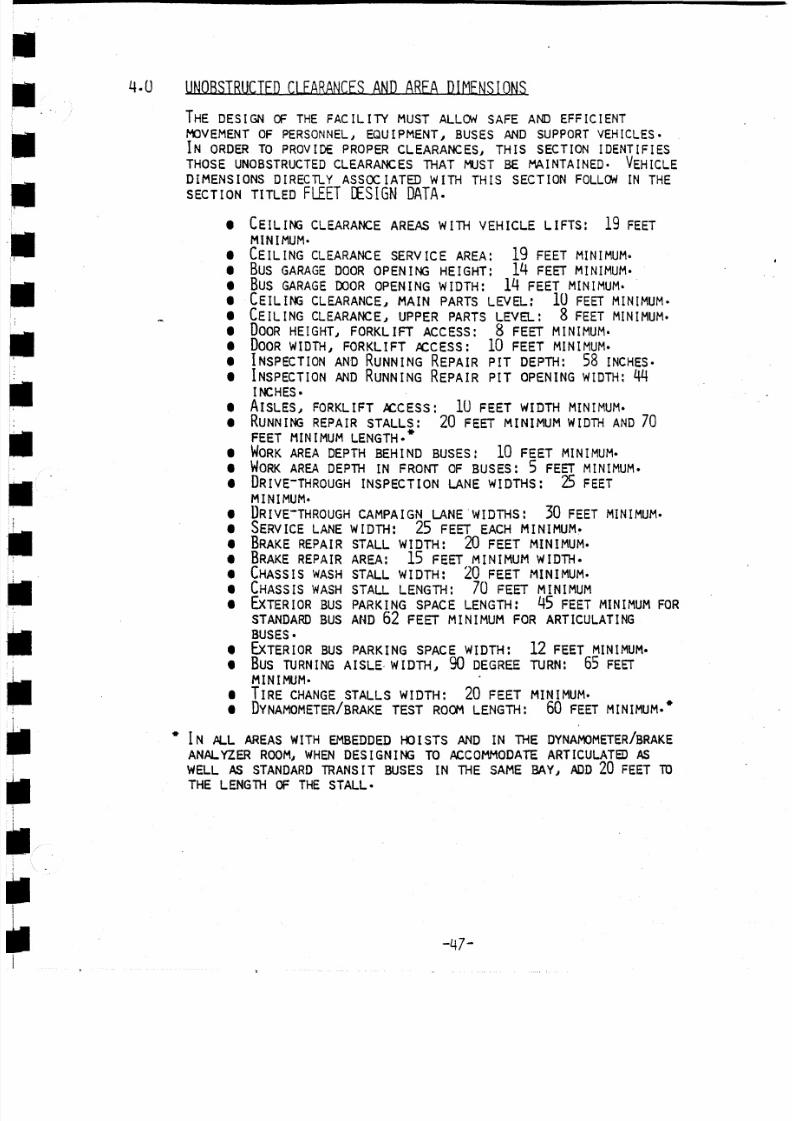
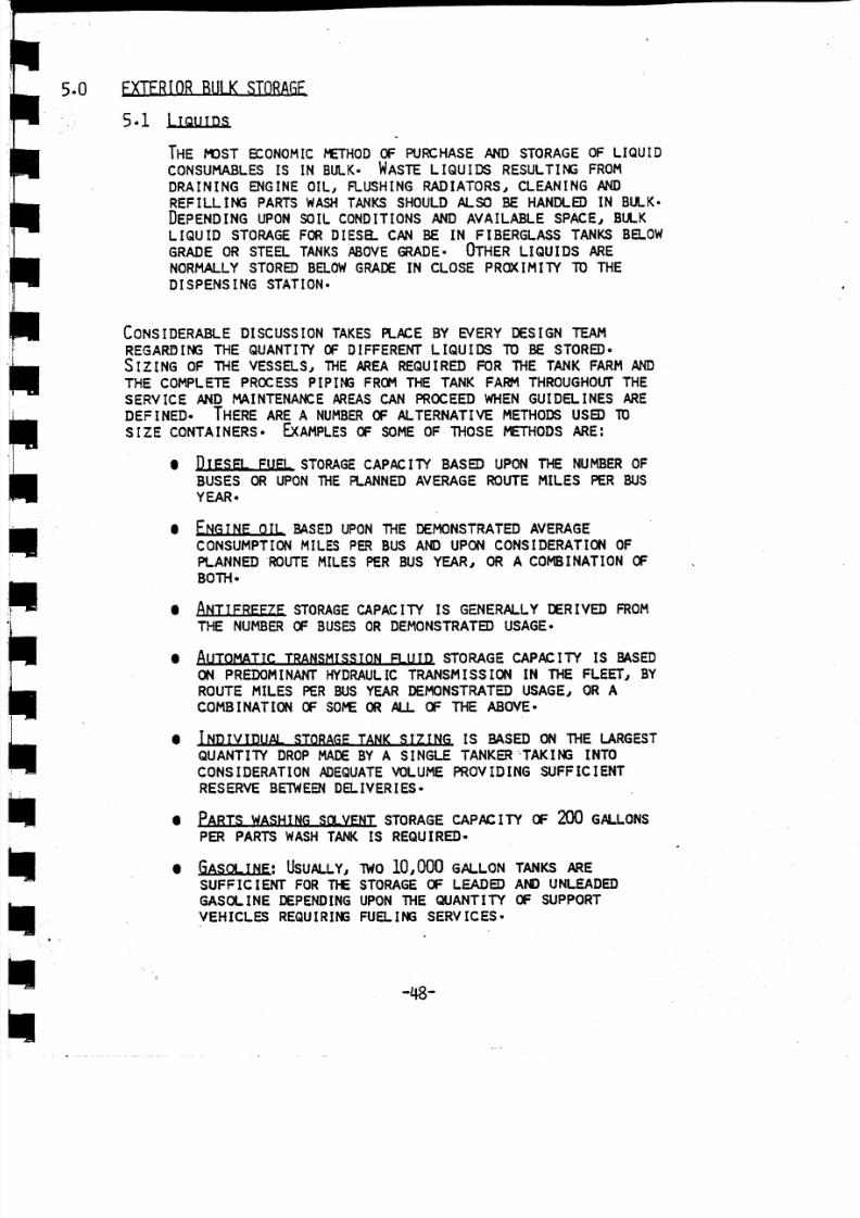

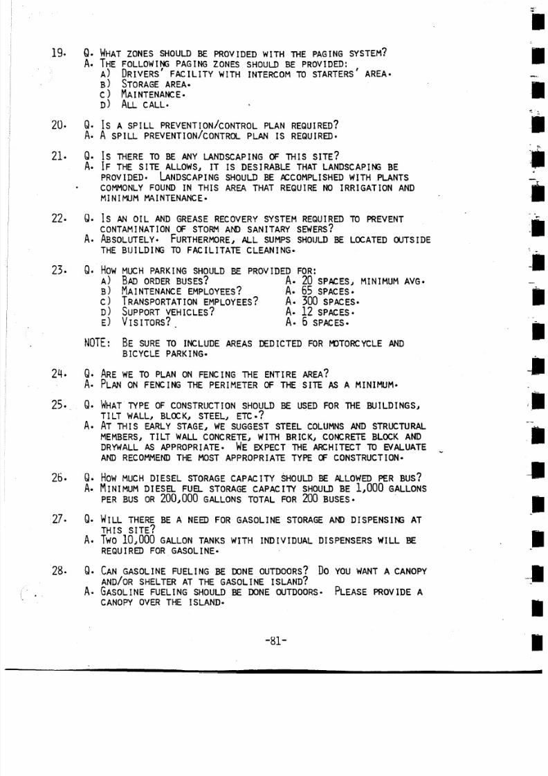
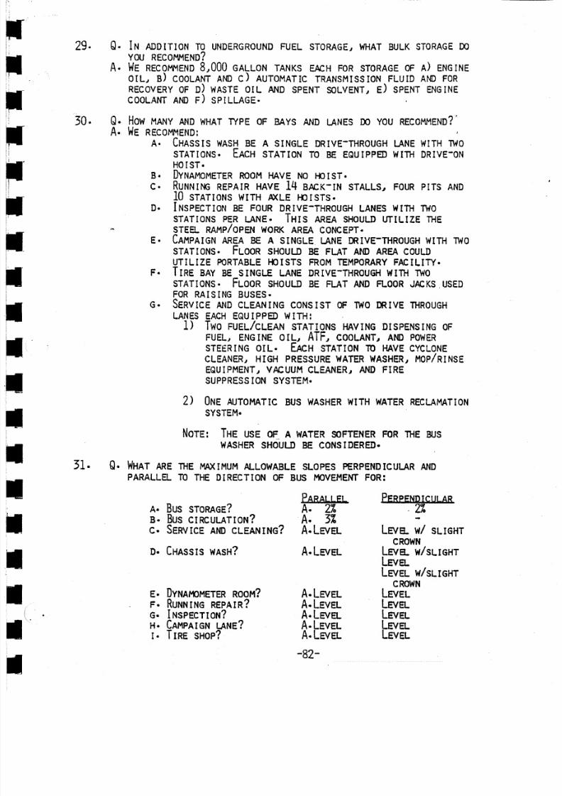


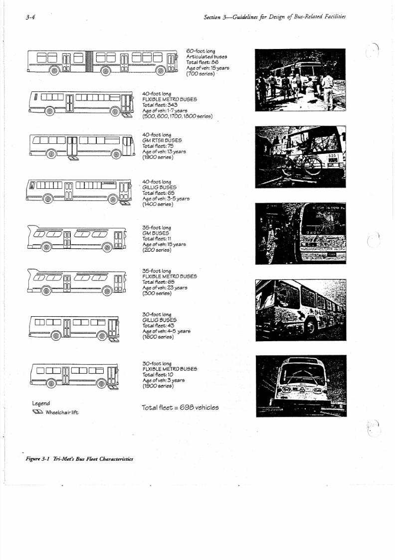
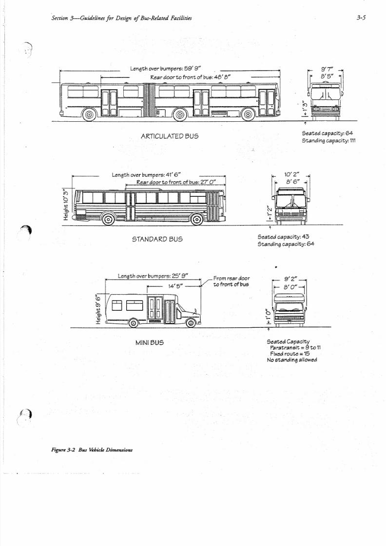


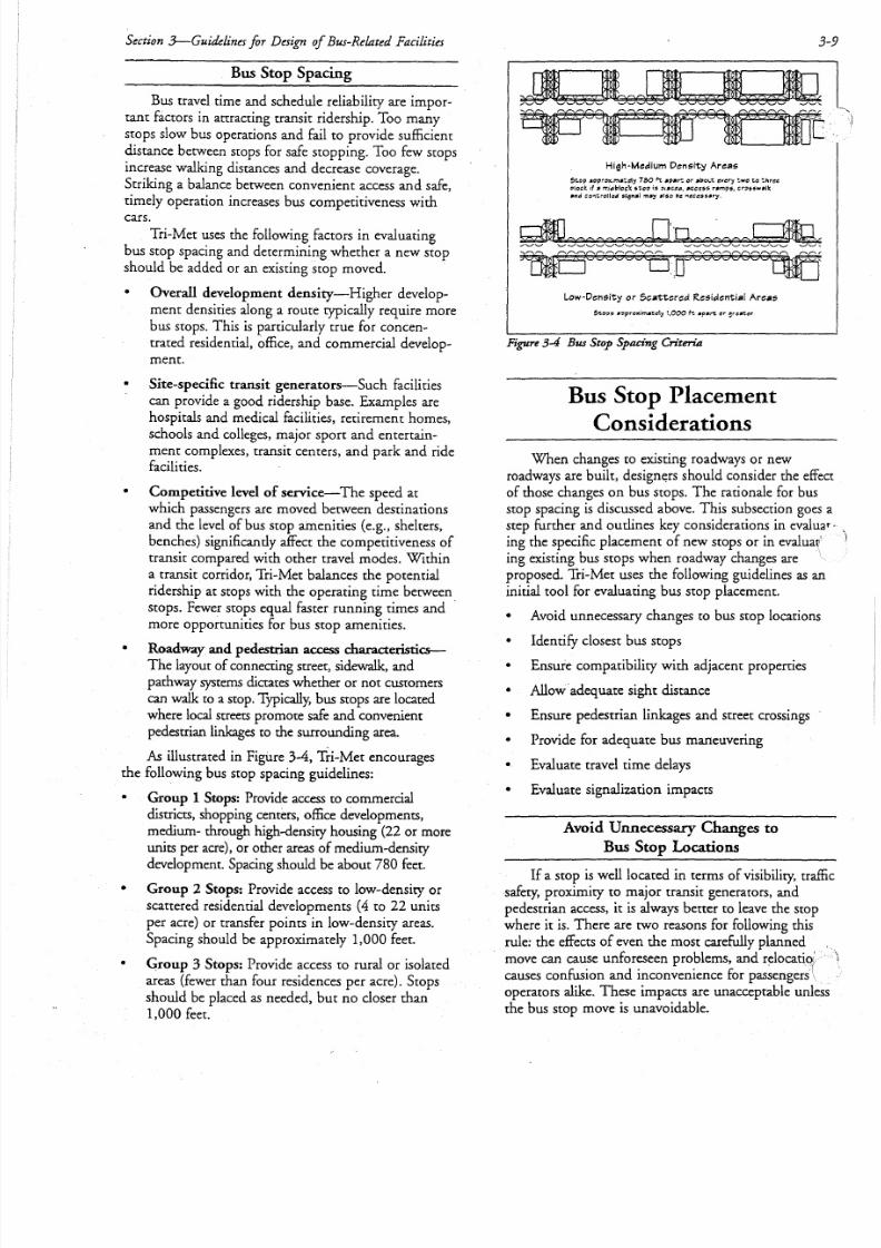

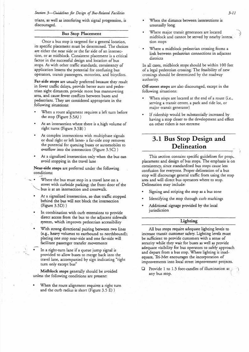
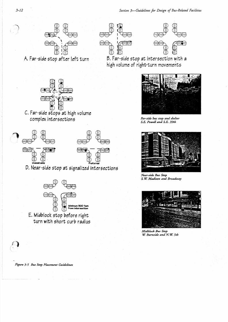


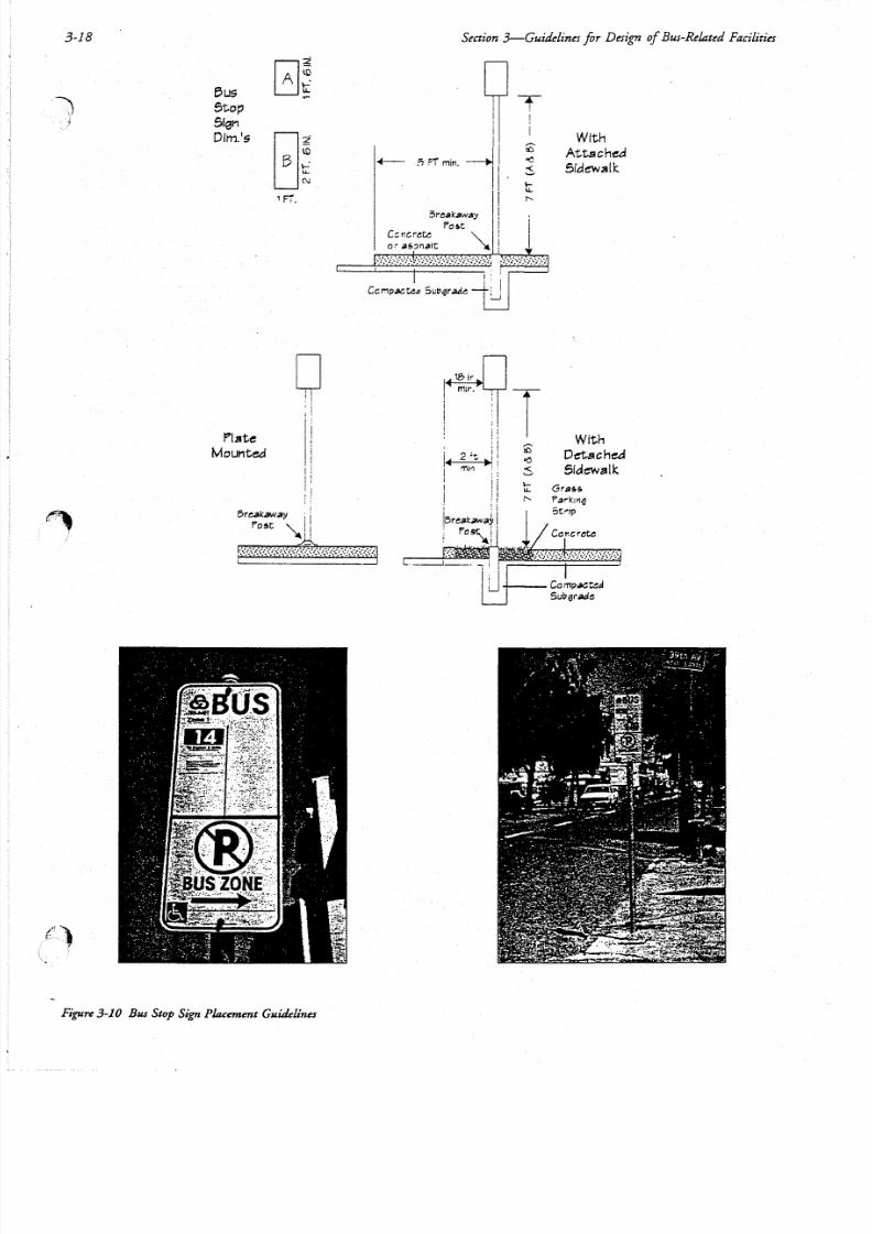
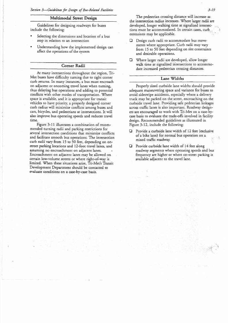
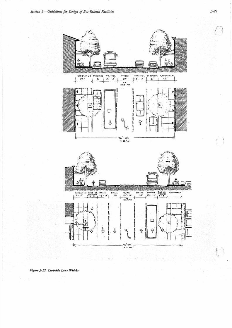
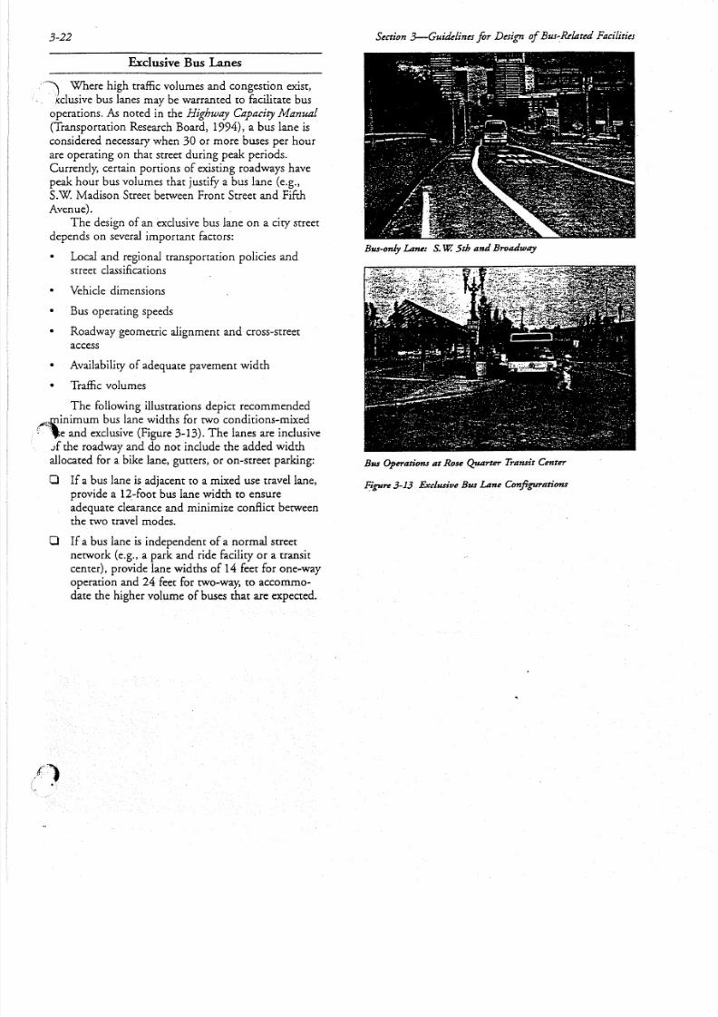
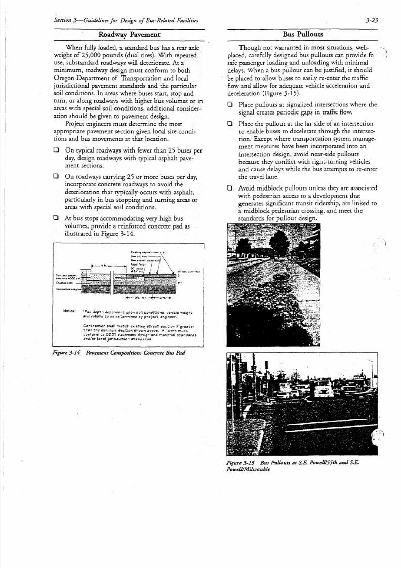
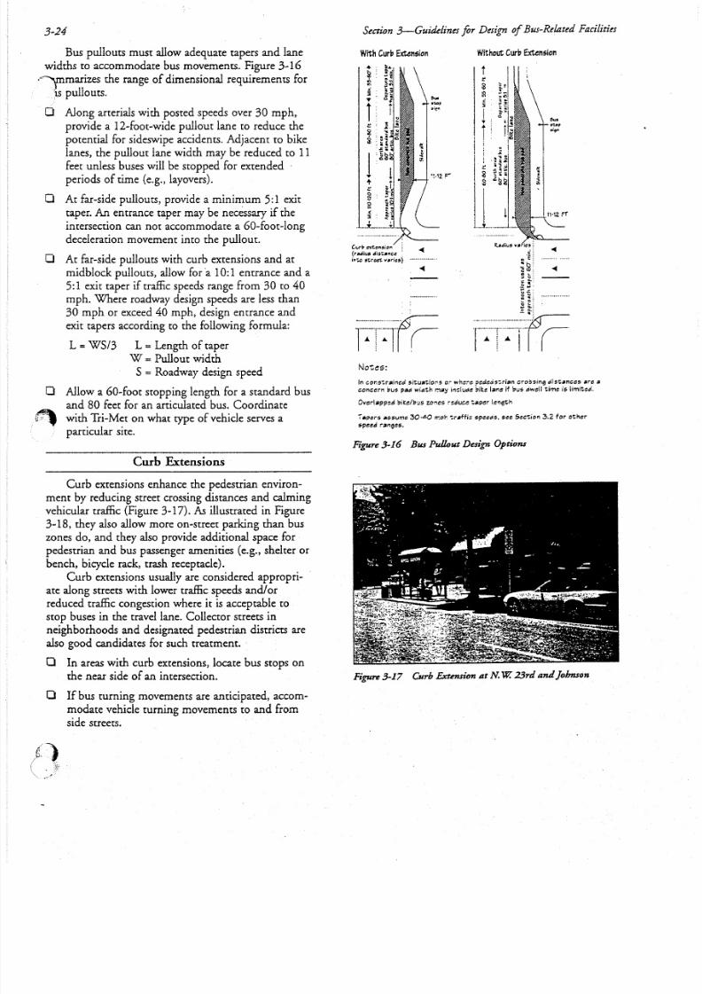

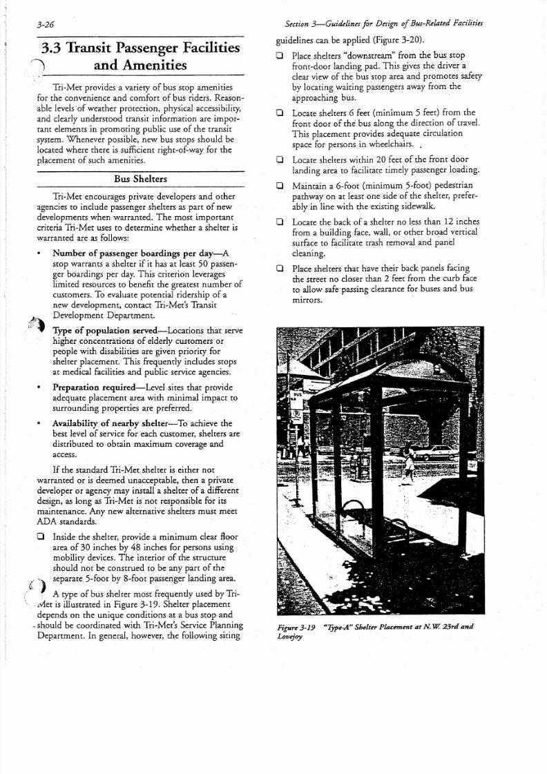


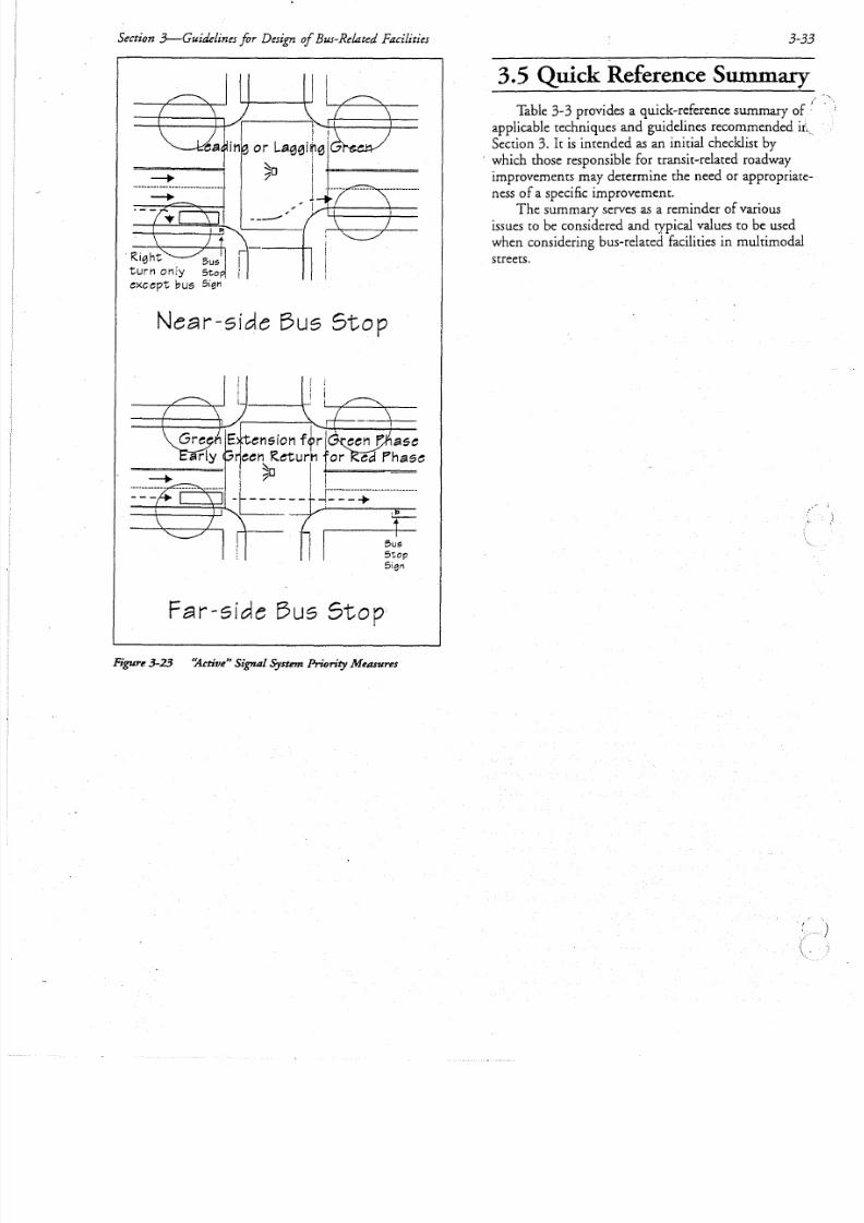

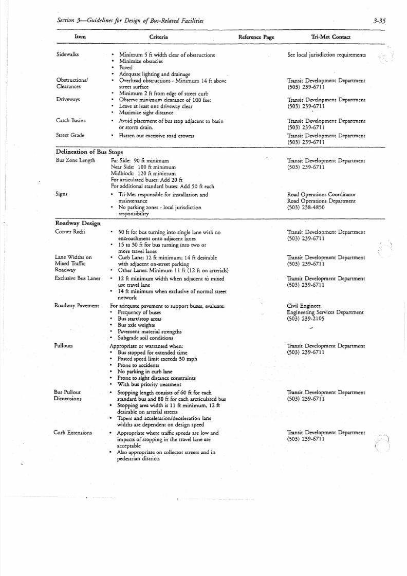
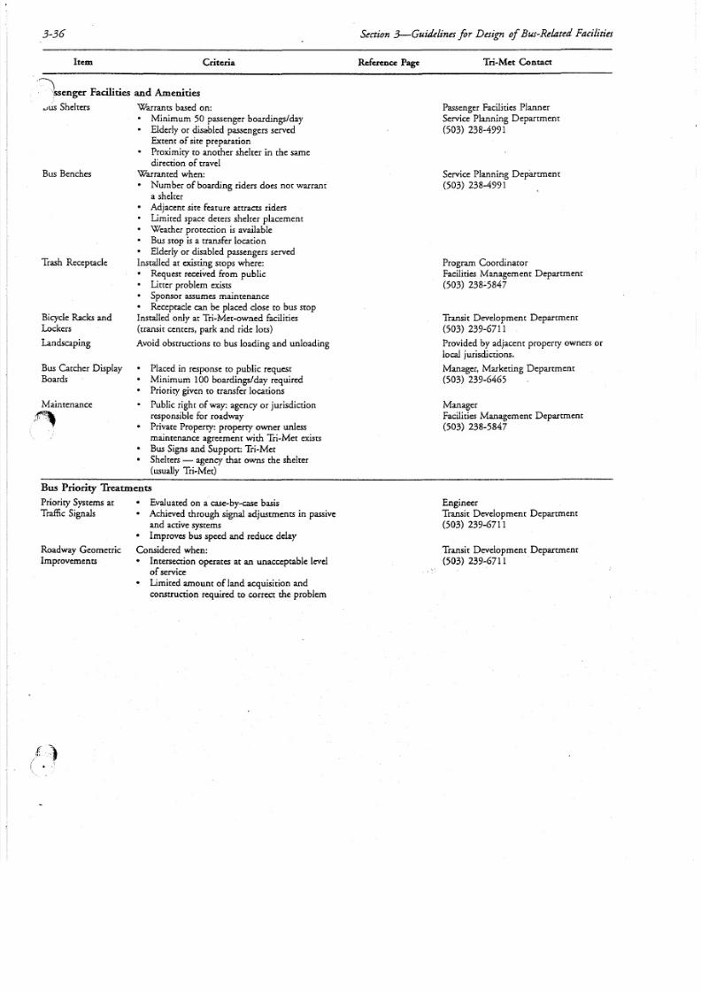


![Elements of Set Theory - CM0832 - EAFIT · Elements of Set Theory - CM0832 ... The objects are called elements (members) of the set.” [Hrbacek and Jech 1999, ... [Enderton 1977].](https://static.documents.pub/doc/80x56/5afe656f7f8b9a68498e43fc/elements-of-set-theory-cm0832-of-set-theory-cm0832-the-objects-are-called.jpg)


