62
ELETTROPOMPE CENTRIFUGHE NORMALIZZATE END-SUCTION CENTRIFUGAL ELECTRIC PUMPS NCBZ NCBKZ 50Hz

ELETTROPOMPE CENTRIFUGHE NORMALIZZATEEND-SUCTION CENTRIFUGAL ELECTRIC PUMPS
NCBZNCBKZ50Hz
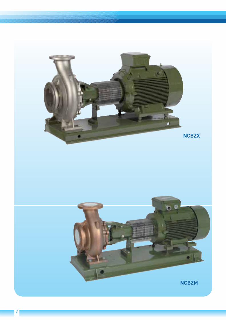
NCBZX
NCBZM
2

NCBNCBX
NCB-M
NCBKNCBKX
3

4

5
2900 1/min
1450 1/min
1450 1/min
950 1/min
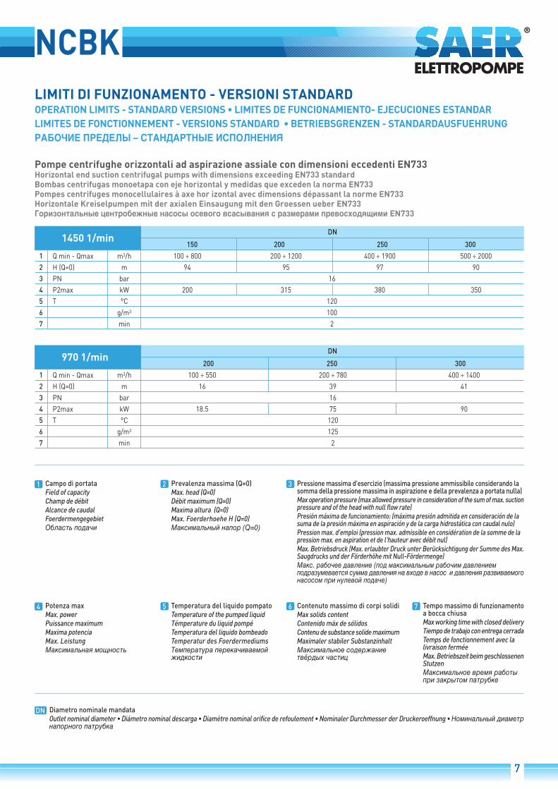
NCBK
150 200 250 300
1 Q min - Qmax m3/h 100 ÷ 800 200 ÷ 1200 400 ÷ 1900 500 ÷ 2000
2 H (Q=0) m 94 95 97 90
3 PN bar 16
4 P2max kW 200 315 380 350
5 T °C 120
6 g/m3 100
7 min 2
DN1450 1/min
1 2 3
4 5 6 7
DN
200 250 300
1 Q min - Qmax m3/h 100 ÷ 550 200 ÷ 780 400 ÷ 1400
2 H (Q=0) m 16 39 41
3 PN bar 16
4 P2max kW 18.5 75 90
5 T °C 120
6 g/m3 125
7 min 2
DN970 1/min
7

38
13
2
4
5
6
NCBK

Corpo pompa e disco porta tenuta progettati con spessoriidonei per garantire la maggiore resistenza e durata allepressioni d'esercizio. Ampia scelta di materiali (Ghisa grigiaEN-GJL-250, Ghisa sferoidale EN-GJS-500, bronzo marinoG-CuSn 10, Acciaio inossidabile AISI 316). Flangiatura inPN 16.
Di serie, anelli di usura semplici da sostituire, persalvaguardare il corpo pompa e la girante.
Disegno idraulico progettato con sistemi CFD e ottimizzatoper ottenere i migliori livelli di efficienza idraulica abbinatiad una vasta gamma di curve Portata-Prevalenza. Ampiascelta di materiali (Ghisa, Acciaio al carbonio, bronzo marinoG-CuSn 10, Acciaio inossidabile AISI 316).
Differenti configurazioni di tenuta meccanica o a badernaa seconda delle esigenze dell'utilizzatore, in funzione dellecaratteristiche del fluido e delle condizioni di impiego.
Cuscinetti a sfere sovradimensionati e preservati dagliagenti esterni per offrire una rumorosità di funzionamentoridotta e una vita utile elevata senza necessità dimanutenzione. Su richiesta versioni disponibili con cuscinettiin bagno d'olio e con oliatore a livello costante.
Di serie, Albero in acciaio inossidabile AISI 431 progettatoper resistere ai carichi flesso-torsionali generati e protettoda sistemi antiusura. A richiesta, alberi in materiali diversi(Duplex, AISI 630).- Semplice disassemblaggio della parte idraulica, estraibile senza la necessità di rimuovere il corpo pompa dalle tubazioni. Sistema “back pull out”- Profilo dell'aspirazione studiato per aumentare la capacità
di aspirazione, ridurre l' NPSH e la possibilità di cavitazione.
Le pompe serie NCBK sono interamente realizzatenegli stabilimenti SAER in Italia.
1.
2.
3.
4.
5.
6.
Pump body and seal holding disk designed with suitablethickness to guarantee greater resistance and life to theexercise pressures. A wide range of materials (cast ironEN-GJL-250, spheroidal cast iron EN-GJS-500, marinebronze G-CuSn 10, stainless steel AISI 316). Flanges in PN16.
Standard for all versions, wear rings, easy to replace, toprotect the pump body and the impeller (optionals).
Hydraulic designed with CFD systems and optimized inorder to obtain the best hydraulic efficiency levels, combinedwith a wide range of Capacity-Discharge Head curves. Widerange of materials (cast iron, marine bronze G-CuSn 10,stainless steel AISI 316).
Different configurations of mechanical seal or gland packingaccording to the user's requirements, based on the fluidcharacteristics and the use conditions.
Oversized ball bearings and protected from outer agentsto offer a reduced working noise and a long service lifewithout necessity of maintenance. Available versions withoil soaked bearings and with a constant-level oil feeder ondemand.
Standard: stainless steel AISI 431 shaft designed to resistto the bending-torsion load generated and protected byanti-wear systems. On demand, shafts made with differentmaterials (Duplex, AISI 630).- Hydraulic part simple to disassemble, extractable without
needing to remove the pump body from the pipes (Backpull out system).
- Suction profile conceived to increase the suction capacityand to reduce the NPSH and the possibility of cavitation.
NCBK series pumps are entirely manufactured in theSAER plants in Italy.
1.
2.
3.
4.
5.
6.
Cuerpo bomba y disco de sellado diseñados con espesoresidóneos para garantizar una mayor resistencia y duracióna las presiones de ejercicio. Amplia gama de materiales(fundición gris EN-GJL-250, hierro esferoidal EN-GJS-500,bronce marino G-CuSn 10, acero inoxidable AISI 316).Bridas en PN 16.
Estándar para todas las versiones, anillos de desgaste,fácil de reemplazar, para proteger el cuerpo de la bombay el impulsor (opcional).
Proyecto hidráulico con sistemas CFD y optimizado paralograr el mayor nivel de eficiencia hidráulica en combinacióncon una amplia gama de curvas de caudal-altura. Ampliavariedad de materiales (fundición gris, bronce marino G-CuSn 10, acero inoxidable AISI 316).
Diferentes configuraciones de cierre mecánico oempaquetadura de acuerdo a las necesidades del usuario,dependiendo de las características del fluido y lascondiciones de servicio.
Cojinetes de bolas sobredimensionados y preservados delos agentes exteriores para ofrecer una funcionamientosilenzioso y larga vida útil sin mantenimiento. Las versionesdisponibles bajo petición concojinetes en baño de aceitecon y con lubricador de nivel constante.
Estándar, eje en acero inoxidable AISI 431 diseñado parasoportar las cargas generadas flexión-torsión y sistemasde protección contra el desgaste. Previa solicitud, ejes endiferentes materiales (Duplex, AISI 630).- Simple desmontaje de la parte hidráulica, extraible sin
la necesidad de remover el cuerpo bomba de la tubería(sistema “Back pull out “).
- Perfil de aspiración diseñado para aumentar la capacidadde succión, reducir el NPSHy la posibilidad de cavitación.
Las bombas serie NCBK están totalmente fabricadas enlas plantas SAER en Italia.
1.
2.
3.
4.
5.
6.
Corps de pompe et disque porte-garniture avec desépaisseurs appropriées pour assurer la solidité et ladurabilité aux pressions d'exercice. Large choix de matériaux(Fonte grise EN-GJL-250, Fonte ductile EN-GJS-500, Bronzemarin G-CuSn 10, Acier inox AISI 316). Brides en PN 16.
Standard pour tout les versions, bagues d'usure faciles àremplacer, pour protéger le corps de pompe et la roue (enoption).
Dessin hydraulique conçu avec système CFD et optimisépour atteindre les plus hauts niveaux de rendementhydrauliques combiné à un large gamme de courbes débit-prévalence . Large choix de matériaux (Fonte, bronze marinG-CuSn 10, Acier inoxydable AISI 316).
Différentes configurations de garniture mécanique oud'étancheité, selon les besoins de l'utilisateur, en fonctiondes caractéristiques du fluide et des conditions de service.
Roulements à billes surdimensionnés et préservés desagents extérieurs pour assurer un faible bruit defonctionnement et une durée de vie élevé sans besoind'entretien. Sur demande versions disponibles avecroulements à bain d'huile et avec huileur à niveau constant.
Standard, Arbre en acier inox AISI 431 conçu pour résisteraux chargements flexion-torsion générés et protégé pardes systèmes contre l'usure. Sur demande, arbres endifférents matériaux (Duplex, AISI 630).- Démontage facile de la partie hydraulique, qui peut être
extraite sans la nécessité d'enlever le corps de pompe de la tuyauterie (systeme «Back pull out »).- Profil d'aspiration conçu pour augmenter la capacité d'aspiration, réduire le NPSH et la possibilité de cavitation.
Les pompes série NCBK sont fabriquées entièrementdans les Etablissements SAER en Italie.
1.
2.
3.
4.
5.
6.
Pumpenkörper und Dichtungsträgerdeckel sind mit einersolchen Wandstärke entwickelt worden, dass gegenüberden beim Betrieb auftretenden Drücken eine höhereWiderstandsfähigkeit und Lebensdauer gewährleistet wird.Große Auswahl an Materialien: Grauguss EN-GJL-250,Sphärograuguss EN-GJS-500, meerwassertaugliche BronzeG-CuSn 10, Edelstahl AISI 316. Flansche für PN16.
Serienmaessig, zum Schutz des Pumpenkörpers und desLaufrades Versionen mit einfach zu wechselndenVerschleißringen.
Dessen hydraulisches Strömungsbild mit CFD-Systemenentwickelt und optimalisiert wurde, um höchstehydraulische Effizienz in Verbindung mit einer großenAnzahl an Kurven für Fördermengen und Förderhöhen zugewährleisten. Große Auswahl an Materialien : Grauguss,Kohlenstoffstahl, meerwassertaugliche Bronze G-CuSn10, Edelstahl AISI 316.
Gemäß den Anforderungen der Kunden in Verbindung mitden Eigenschaften der zu pumpenden Flüssigkeit und denEinsatzbedingungen verschiedene Gleitring- oderStopfbuchsendichtungen möglich.
Überdimensionierte und vor Umwelteinflüssen geschützteKugel lager gewährle isten e ine ger ingereGeräuschentwicklung und höhere Standzeit bei geringererWartung. Auf Anfrage Kugellager im Ölbad mit Öler zurAufrechterhaltung des konstanten Ölniveaus.
Serienmäßig: Durch Antiverschleiss-Systeme geschützteWelle aus torsionsbeständigem Edelstahl AISI 431. AufAnfrage Wellen aus anderen Materialien erhältlich.- Einfacher Ausbau der hydraulischen Bauteile, ohne dass
dafür der Pumpenkörper von den Leitungen getrennt werden muss («Back pull out » system).- Das Ansaugprofil wurde so entwickelt, dass bei gleichzeitiger Erhöhung der Ansaugkapazität der NPSH- Wert und somit die Möglichkeit der Kavitation verringert wird.
Die Pumpen der Serie NCBK sind voellig in den SAER-Werken in Italien hergestellt
1.
2.
3.
4.
5.
6.
1.
2.
3.
4.
5.
6.
IT GB ES
F DE RUS
39

40
NCBK-NCBKZIMPIEGHIImpianti di ricircolo, di riscaldamento, di condizionamento, direcupero calore, impianti di approvvigionamento idrico, gruppi dipressurizzazione.
CARATTERISTICHE COSTRUTTIVENCBK: pompe centrifughe monostadio ad spirazione assiale, adasse nudo;NBCKZ: elettropompe centrifughe su base;Il gruppo motore e la parte rotante della pompa, sono estraibilisenza dovere rimuovere il corpo pompa dalle tubazioni dell'impianto.Idraulica:Corpo pompa con dimensioni eccedenti la norma EN 733.Girante chiusa equilibrata dinamicamente e con fori di equilibrioper il bilanciamento della spinta assiale.Albero interamente in acciaio inox.Anelli di usura di serie.Cuscinetti a sfera lubrificati a grasso ( su richiesta, lubriificazionein bagno d'olio).Flange (UNI EN 1092-2) PN16.Tenuta a baderna (a richeista, tenuta meccanica normalizzatasecondo UNI EN 12756 o altre tenute meccaniche) .Per i materiali di costruzione fare riferimento a pag. 42.Motore, serie NCBKZ: asincrono con ventilazione esterna (TEFC).Protezione: IP55Isolamento: classe FTensioni standard, frequenza 50 Hz,: 220-240V fino a 4 kW,380-415V / 660-720V a partire da 5,5 kW.Motori in classe di efficienza IE2 secondo IEC 60034-30. a richiestaaltre versioni.
DATI CARATTERISTICIDN aspirazione: da 200 a 350; DN mandata: da 150 a 300;@ 1450 1/min: Qmax: 2000 m3/h - Hmax: 97 m@ 970 1/min: Qmax: 1400 m3/h - Hmax: 41 mTemperatura del liquido pompato: da -15°C a +120°CPressione massima d'esercizio (massima pressione ammissibileconsiderando la somma della pressione massima in aspirazionee della prevalenza a portata nulla):
TOLLERANZE PRESTAZIONIPompe: UNI-EN-ISO 9906 Appendice A - a richiesta livello 1Motore: norme IEC 60034-1.
INSTALLAZIONE E CARATTERISTICHE DI FUNZIONAMENTOLe pompe serie NCBK possono essere posizionate con l'asseorizzontale, inclinato o verticale sempre con il motore versol'alto (chiedere informazioni al servizio tecnico).Le caratteristiche di funzionamento di catalogo e di targhettasi intendono per servizio continuo ed acqua pulita, (peso specifico= 1000 kg/m3) con altezza manometrica massima di aspirazionedi 1,5 m c.a. Per altezze manometriche superiori e fino ad unmassimo di 6 m. c.a., le caratteristiche si riducono nei varivalori di portata. La tubazione aspirante deve essereassolutamente stagna e per i dati di catalogo deve avere iseguenti diametri minimi (Tubazioni di diametro inferioreriducono i valori di portata):
VERSIONI SPECIALI E OPZIONIPompeMateriali di costruzione: acciaio inossidabile AISI 316, Bronzomarino G-CuSn10, Ghisa sferoidale.Tenute meccaniche diverseVersione con cuscinetti lubrificati in bagno d'olioMotoriTensioni specialiClassi di efficienza diverseMotore con protezione PTCAltre versioni a richiesta
ACCESSORI A RICHIESTAKit controflangie
IT GB ES
NCBK
NCBKX
NCBKM
Versione
Ghisa
Acciaioinossidabile
Bronzo
Temperatura delliquido pompato
Materiale PN maxstandard
-15°C/ +120°C
-15°C/ +50°C
+50°C/ +120°C
-15°C/ +120°C
16
16
10
16
Temperatura max ambiente: 40°C (oltre chiedere informazioni).
DN (aspirazione pompa)[mm] DN (tubo aspirazione)[mm]
200
250
300
350
350
400
500
600
USESRecircling plants, heating, air conditioning, heat recovery, plantsof water supply procurement, pressurising units.
CONSTRUCTIVE CHARACTERISTICSNCBK: bareshaft end-suction single stage centrifugal pumps,NCBKZ: end-suction centrifugal pumps with electric motor, on abase.The motor unit and the rotating part of the pump can be takenaway without removing the pump body from the system piping.Hydraulics:Pump body with dimension exceeding EN 733 rules.Closed impeller dynamically balanced and with balance holes forthe balancing of the axial thrust.Shaft completely in stainless steel.Wear rings.Greased ball bearings (on request, oil lubricated ball bearings).Flanges (UNI EN 1092-2): PN16.Soft packing seal (on request, mechanical seal normalized accordingto UNI EN 12756 or otehrs special seals).For constructive materials, please, refer to page 42.Motor, NCBKZ series: asynchronous with external ventilation(TEFC)Protection: IP55Insulation: class FStandard tensions, Frequency 50 Hz, 220-240V up to 4 kW, 380-415V / 660-720V starting from 5,5 kW.Motors with efficiency class IE2 according to IEC 60034-30, differentversions on request.
FEATURESDN aspiration: from 200 up to 350;- DN delivery: from 150 up to300;@ 1450 1/min: Qmax: 2000 m3/h - Hmax: 97 m@ 970 1/min: Qmax: 1400 m3/h - Hmax: 41 mTemperature of the pumped liquid: from -15°C up to +120°CMax operation pressure (max allowed pressure in considerationof the sum of max. suction pressure and of the head with null flowrate):
PERFORMANCE TOLERANCESPumps: UNI EN ISO 9906 Appendix A, Level 1 on request.Motor: IEC 60034-1 rules.
INSTALLATION AND OPERATION CHARACTERISTICSThe NCBK pumps can be positioned with horizontal, sloping orvertical axis always with the motor upwards (please, verify withour technical dep.). The operating characteristics of the catalogueand label are to be understood for continuous service and withclear water (specific weight = 1000 kg/m3) with a maxmanometric suction height of approximately 1,5 m. For highermanometric heights and up to a max of approximately 6 m, thecharacteristicsdecrease in the various delivery data. The suction piping mustbe absolutely hermetic and for the catalogue data it must havethe following minimum diameters (pipes of smaller diametersreduce the delivery values):
SPECIAL VERSIONSPumpConstructive materials: cast stainless steel AISI316, MarineBronze G-Cusn10, spheroidal cast iron.Different mechanical sealsVersion with oil bath bearingsMotorSpecial tensionsDifferent levels of efficiencyMotors with PTC protectionOther special version on request
ACCESSORIES ON REQUESTKit counterflanges
APLICACIONESSistemas de recirculación, calefacción, aire acondicionado,recuperación de calor, instalaciones de abastecimiento hídrico,grupos de presurización.
CARACTERISTICAS DE CONSTRUCCIONNCBK: bombas centrifugas monoetapa a eje libreNCBKZ: electrobombas centrifugas sobre bancada;El grupo motor y la parte giratoria de la bomba se extraen sintener que desmontar el cuerpo de la bomba de las tuberías de lainstalación.Hídraulica:Cuerpo de bomba con dimensiones que exceden la norma EN733;Impulsor cerrado equilibrado dinámicamente y con orificios deequilibrio por el balanceo del empuje axial de eje.Eje completamente en acero inoxidable.Anilos de desgaste.Rodamientos de bolas engrasados (bajo pedido, en baño de aceite).Bridas (UNI EN 1092-2): PN16.Empaquetadura baderna (bajo pedido empaquetadura mécanicaestándarizada según UNI EN 12756, otras empaquetadurasespeciales bajo demanda).Por los materiales de construcción hacer referencia a la página42.Motor, serie NCBKZ: asíncrono con ventilación exterior (TEFC)Protección: IP55Aislamiento: clase FTensiones estándard, Frecuencia 50 Hz, 220-240V hasta 4 kW,380-415V / 660-720V a partir de 5,5 kW.Motores con eficiencia IE2 según IEC 60034-30, versiones diferentesa petición de los interesados.
LIMITES DE EMPLEODN aspiración: de 200 hasta 350; DN descarga: de 150 hasta 300;@ 1450 1/min: Qmax: 2000 m3/h - Hmax: 97 m@ 970 1/min: Qmax: 1400 m3/h - Hmax: 41 mTemperatura del liquido bombeado: de -15°C hasta +120°CPresión máxima de funcionamiento: (máxima presión admitidaen consideración de la suma de la presión máxima en aspiracióny de la carga hidrostática con caudal nulo):
TOLERANCIAS PRESTACIONESBombas: UNI EN ISO 9906 Parrafo A, Nivel 1 bajo demanda.Motor: normas IEC 60034-1.
INSTALACION Y CARACTERISTICAS DE FUNCIONAMIENTOLas bombas NCBK pueden montarse en posición horizontal,vertical o angulada, pero siempre con el motor situado en laparte superior (consultar verificación). Las caracteristicas defuncionamiento indicadas tanto en el catálogo como en la placa,se refieren a un uso continuo y en agua limpia, (peso específico= 1000 kg/m3) con una altura manométrica máxima de aspiraciónde aproximadamente 1,5 m.Para alturas manométricas superiores y hasta un máximo deaproximadamente 6 m, las caracteristicas se reducen en losdiferentes valores de caudal. La tubería de aspiración ha deser completamente estanca y por los datos del catálogo debetener los siguientes diámetros minimos (tuberías de diámetroinferior reducen los valores de caudal):
VERSIONES ESPECIALESBombaMateriales de construcción: acero inoxidable AISI316 defundicion, Bronce Marino G-CuSn10, hierro fundido esferoidalEmpaquetaduras mécanicas diferentesVersion con rodamientos en baño de aceiteMotorTensiones especialesNiveles diferentes de eficienciaMotor con proteccion PTCOtra versión especial a petición
ACCESORIOS BAJO PEDIDOConjunto bridas
DN (pump suction) [mm] DN (suction pipe) [mm]
200
250
300
350
350
400
500
600
NCBK
NCBKX
NCBKM
Version
Cast iron
Stainlesssteel
Bronze
Temperature ofthe pumped liquid
Material PN maxstandard
-15°C/ +120°C
-15°C/ +50°C
+50°C/ +120°C
-15°C/ +120°C
16
16
10
16
Max environment temperature: 40°C (for higher temperature, please, verify).
NCBK
NCBKX
NCBKM
Versión
Hierro fundido
Acero inox
Bronce
Temperatura delliquido bombeado
Material PN maxstandard
-15°C/ +120°C
-15°C/ +50°C
+50°C/ +120°C
-15°C/ +120°C
16
16
10
16
Temperatura máxima ambiente: 40°C (para valores superiores consultar verificación).
DN (aspiración bomba) [mm] DN (tubo de aspiración) [mm]
200
250
300
350
350
400
500
600

41
APPLICATIONInstallation de circulation, réchauffage, climatisation, récupérationthermique, installations de approvisionnement d'eau, unités desurpression.
CARACTERISTIQUES DE CONSTRUCTIONNCBK: pompes centrifuges mono étape avec aspiration axiale, aaxe nu;NCBKZ: électropompes centrifuges sur base.Le groupe moteur et la partie rotative de la pompe peuvent êtreenlevés sans devoir retirer le corps de la pompe des canalisationsdu système.Hydraulique: corps de pompe avec dimensions dépassant la normeEN733,Roue serrée équilibrée dynamiquement et avec trous d'équilibrepour balancer la poussée axiale.Arbre complètement en acier inoxydable.Bagues d'usure.Roulements à billes graissés (surdemande, version avecroulements lubrifiés par l'huile).Brides (UNI EN 1092-2) PN16.Garniture baderne (garniture mécanique normalisée selon UNIEN 12756 ou autres garniture spéciales sur demande).Pour les matériaux constructifs merci de se référer à la page 42.Moteur, série NCBKZ: asynchrone avec ventilateur extérieur(TEFC).Protection: IP55Isolement: classe FVoltages de série, Fréquence 50 Hz, 220-240V jusqu'à 4 kW, 380-415V / 660-720V à partir de 5,5 kW.Moteurs avec class de rendement IE2 selon IEC 60034-30. versionsdifférentes sur demande.
CARACTERISTIQUES TECHNIQUESDN aspiration: de 200 à 350 ; DN refoulement: de 150 à 300.@ 1450 1/min: Qmax: 2000 m3/h - Hmax: 97 m@ 970 1/min: Qmax: 1400 m3/h - Hmax: 41 mTempérature du liquide pompé: de -15°C à +120°CPression max. d'emploi (pression max. admissible en considérationde la somme de la pression max. en aspiration et de l'hauteuravec débit nul):
TOLERANCES DE PERFORMANCEPompes: UNI EN ISO 9906 Annexe A,, niveau 1 sur demande.Moteur: normes IEC 60034-1.
INSTALLATION ET CARACTERISTIQUES DE FONCTIONNEMENTLes électropompes peuvent être utilisées sur axe horizontal,incliné ou vertical toujours avec le moteur pointé vers le haut(demander une vérification). Les caractéristiques defonctionnement du catalogue et de la plaque sont entenduespour fonctionnement continu et avec eau propre, (poids spécifique= 1000 kg/m3) avec hauteur manométrique d'aspiration deapproximativement 1,5 m. Pour hauteurs manométriquessupérieures et jusqu'à un maximum de 6 m, les caractéristiquesse réduisent dans les valeurs du débit. La tuyauterie aspirantedoit être absolument étanchée et pour les données du catalogueelle doit avoir les diamètres minimum suivants (tuyauteries dediamètre inférieur réduisent les valeurs du débit):
VERSIONS SPECIALESPompeMatériaux constructifs : acier inoxydable AISI316 fondu, bronzemarin G-CuSn10, fonte sphéroïdale.Garnitures mécaniques différentesVersion avec roulements lubrifiés par l'huileMoteurNiveaux différents de rendementVoltages spéciauxMoteur avec protection PTCAutres versions spéciales sur demande
ACCESSOIRES SUR DEMANDEKit contre-brides
F DE RUSVERWENDUNGUmwälzanlagen, Heizung, Kühlung, Wärmerückgewinnung,Wasserversorgung, Druckerhöhungsgruppen.
KONSTRUKTIONSEIGENSCHAFTENNCBK: Kreiselpumpen auf freier Welle;NCBKZ: Kreiselelektropumpen auf Grundplatte;Das Motorenaggregat und der sich drehende Teil der Pumpekönnen herausgezogen werden, ohne dabei das Pumpengehäusevon den Leitungen der Anlage trennen zu müssen.Hydraulik: Pumpengehäuse mit Abmessungen und Leistungenueber Norm EN 733. Geschlossenes Laufrad dynamischausgewuchtet und mit Gleichgewichtlöchern für den Ausgleichdes Längsdrucks. Welle völlig aus rostfreiem Stahl.Einfach zu wechselnden Verschleißringen.Mit Fett geschmierte Kugellager (auf Anfrage: im Ölbad befindlicheKugellager).Flansche (UNI EN 1092-2) PN16.Stophbuchse (auf Anfrage: Mechanische Gleitringdichtungen nachNormen UNI EN 12756 oder andere Sonderdichtungen)Für die Materialien: Siehe Seite 42.Motor, Serie NCBKZ: asynchron mit Außenbelüftung (TEFC).Schutzart: IP55Isolation: Klasse FStandardspannungen Frequenz: 50 Hz : 220-240V bis 4 kW, 380-415V / 660-720V ab 5,5 kW.Motore in Effizienzklasse IE2 gemäß IEC-60034-30, auf Anfrageandere Versionen.
TECHNISCHE EIGENSCHAFTENDN Saugen: von 200 bis 350; DN Förderleistung: NCBK-NCBKZ:von 150 bis 300@ 1450 1/min: Qmax: 2000 m3/h - Hmax: 97 m@ 970 1/min: Qmax: 1400 m3/h - Hmax: 41 mTemperatur des Fördermediums: von -15°C bis +120°CMax. Betriebsdruck (Max. erlaubter Druck unter Berücksichtigungder Summe des Max. Saugdrucks und der Förderhöhe mit Null-Fördermenge):
LEISTUNGSTOLERANZENPumpen: UNI EN ISO 9906 Zusatz A, auf Anfrage Stufe 1.Motor: Normen IEC 60034-1.
EINBAU UND BETRIEBSEIGENSCHAFTENDie Pumpen NCBK können in horizontaler Lage aber auchschräg und vertikal arbeiten, dabei immer mit dem Motor nachoben (um Auskunft zur Überprüfung bitten). Die Katalog- undLeistungsschilddaten gelten für Dauerbetrieb mit reinem Wasser(Dichte = 1000 kg/ m3) bei max.manometrischer Saughöhe bisca. 1,5 m.Bei größeren manometrischen Saughöhen bis max. ca. 6 m,werden die Daten der verschiedenen Fördermengen verringert.Die Saugleitung muss absolut dicht sein und folgende Mindest-Durchmesser haben (kleinere Saugleitungen drosseln dieFördermengewerte):
SONDERAUSFÜHRUNGEN und OptionenPumpenMaterialien: Edelstahl AISI 316, Bronze G-CuSn10, SphaerogussVerschiedene mechanische GleitringdichtungenVersionen mit ÖlbadlagerMotorenSonderspannungenVerschiedene EffizienzklassenMotore mit PTC-SchutzAndere Versionen auf Anfrage
SONDERAUSSTATTUNGEN AUF ANFRAGEGegenflanschen Kit
NCBK
NCBKX
NCBKM
Version
Fonte
Acierinoxydable
Bronce
Température duliquide pompé
Matériel PN maxstandard
-15°C/ +120°C
-15°C/ +50°C
+50°C/ +120°C
-15°C/ +120°C
16
16
10
16
Température max ambiance: 40°C (pour des températures supérieuresdemander une vérification).
DN (aspiration pompe) [mm] DN (tuyau aspiration) [mm]
200
250
300
350
350
400
500
600
NCBK
NCBKX
NCBKM
Version
Gußeisen
RostfreierStahl
Bronze
Temperatur desFördermediums
Material PN maxstandard
-15°C/ +120°C
-15°C/ +50°C
+50°C/ +120°C
-15°C/ +120°C
16
16
10
16
Umgebungstemperatur Max.: 40°C (bei höherer Temperatur bitte,überprüfen Sie).
DN (Pumpe-Sauganschluss) - mm DN (Saugleitung) - mm
200
250
300
350
350
400
500
600
NCBK
NCBKX
NCBKM
-15°C/ +120°C
-15°C/ +50°C
+50°C/ +120°C
-15°C/ +120°C
16
16
10
16
200
250
300
350
350
400
500
600

42
NCBK (standard) NCBKX NCBK-M
PTFE
NCBK

43
N.
EPDM VITON®
1
2
3
4/5
B
V
E
FF
Q1
U3
V
GG
EPDM
B
G
E
FF

44
TABELLA DELLE CARATTERISTICHE IDRAULICHETABLE OF THE HYDRAULIC FEATURESTABLA DE LAS CARACTERISTICAS HIDRAULICAS
65,5 65 64 62,5 60,5 57,5 53,5 48 46,5 45 43 41
75 74 72,5 70,5 68 64,5 60,5 55,5 54 52,5 50 47,5
84,5 84 82,5 81 79 76 72,5 68 66,5 65 62 59
94,5 93 91 89 86,7 84 80,5 76 75 73,5 71,3 69
26,7 26,4 25,7 24,5 22,7 20,4 17,2 12,3 10,5
30,9 30,5 29,7 28,6 27 24,8 21,5 17 15,8 14,5 13
36,8 36,4 35,9 34,9 33,6 31,5 28,3 23,3 21,9 20,5 18,8 17 15
45,1 44,9 44 42,5 39,5 36 31,5 30,3 29 27,8 26,5 25
51,5 51 50,5 49 46 43 39 38 37 35,7 34,5 33,2
56,5 56 55 53,7 51,5 49 45,5 44,5 43,5 42,5 41,5 40,3
63,5 63 62,8 61,5 60 58 55 54,3 53,5 52,5 51,5 50,5
74 73,5 73 72,5 71 69 65 63,8 62,7 61,6 60,5 58,8
83 82,5 82 81,5 80 78 75 74 73 72 71 69,6
95 93,5 92,5 91 89 86,5 83,5 82,5 81,5 80,5 79,5 78,2
23,5 22,1 21 19,8 18,4 18 17,6 17,2 16,8 16,3
29 27 26,3 25,6 24,5 24,2 23,9 23,6 23,3 22,9
34 32 31,5 31 30 29,8 29,5 29,2 29 28,6
37,5 35,4 34,6 33,9 33 32,7 32,5 32,3 32 31,7
45 44,9 44,8 44,5 44,4 44,2 44,1 44 43,6
50 49,9 49,8 49,5 49,4 49,3 49,1 49 48,8
56,5 56 55,7 55,5 55,4 55,2 55,1 55 54,8
63 61,5 61 60,5 60,3 60,1 59,9 59,7 59,5
75 72,5 71 69 68,5 68 67,5 67 66,4
84 80,5 79,5 78 77,6 77,2 76,9 76,5 76,1
92 89 88 87,5 87,2 87 86,7 86,5 86,1
97 95 94,5 94 93,7 93,5 93,3 93 92,6
22,5 19,5 19,3
37 36,2 36,1
41 39,5 39,4
50 49,5 49,3
58 57 56,9
72,5 69 68 66,8 66,5 66,1 65,8 65,5 65,2
75,5 72 71 69,8 69,5 69,2 68,8 68,5 68,1
83 79 78 76,8 76,5 76,2 75,8 75,5 75,1
90 85,5 84,5 83,3 83 82,6 82,3 82 81,6
Tipo
TypeP2
kW HP
U.S.g.p.m.
Q m3/h
l/min
H
(m)
NCBKZ4P 150-500D
NCBKZ4P 150-500C
NCBKZ4P 150-500B
NCBKZ4P 150-500A
NCBKZ4P 200-315C
NCBKZ4P 200-315B
NCBKZ4P 200-315A
NCBKZ4P 200-400D
NCBKZ4P 200-400C
NCBKZ4P 200-400B
NCBKZ4P 200-400A
NCBKZ4P 200-500C
NCBKZ4P 200-500B
NCBKZ4P 200-500A
NCBKZ4P 250-315D
NCBKZ4P 250-315C
NCBKZ4P 250-315B
NCBKZ4P 250-315A
NCBKZ4P 250-400D
NCBKZ4P 250-400C
NCBKZ4P 250-400B
NCBKZ4P 250-400A
NCBKZ4P 250-500C
NCBKZ4P 250-500B
NCBKZ4P 250-500AB
NCBKZ4P 250-500A
NCBKZ4P 300-315C
NCBKZ4P 300-315A
NCBKZ4P 300-400C
NCBKZ4P 300-400B
NCBKZ4P 300-400A
NCBKZ4P 300-500D
NCBKZ4P 300-500C
NCBKZ4P 300-500B
NCBKZ4P 300-500A
110 150
132 180
160 220
200 270
37 50
45 60
55 75
90 125
110 150
132 180
160 220
200 270
250 340
315 430
55 75
75 100
90 125
110 150
200 270
200 270
250 340
315 430
250 340
315 430
355 480
400 540
90 125
160 220
200 270
250 340
315 430
250 340
280 380
315 430
355 480
0 440 880 1321 1761 2200 2640 2900 3105 3302 3412 3522 3545
0 100 200 300 400 500 600 700 725 750 775 800 825
1667 3333 5000 6667 8333 10000 11667 12085 12500 12915 13333 13752 15833
NCBKZ 4P

16,5
25,5
33,5
44,5
50,2
62,3
72,3
13,9
20,8
26,7
30,1
41,8
47,9
53,9
58,4
63,3
73,9
83,8
90,7
18,1
35,3
38,7
48,8
56,2
62,8
65,8
72,9
79,4
45
22 20
30,5 28,5
41,5 40 38,5
47
59,5 57,2 55 50
69 67,1 65,1 61,5 53
13 12,5 12 11 8,5
20 19,5 19 18 15,5 12
26 25,6 25,2 24,3 21,5 18,5 16
29,5 29,1 28,7 28 25 21 17
41 40,5 40 39 36,5 34 32,5 29,5 28 22
47,5 47,1 46,7 46 44 41,5 40,3 37,8 36,5 28,5 26,6 24
53,5 53,1 52,8 52 50,5 48,5 47,5 45,3 44 38 35,7 33 30
58 57,6 57,3 56,5 55 53,5 52,5 50,5 49,5 44 42 40 37 33,5
62 61,3 60,5 59 55,5 52,5 50,5 46 42
73 72,4 71,8 70,5 68 64 62,3 57,5
83 82,3 81,5 80 77,5 73,5 71,5 66
90 89,5 89 88 85 81 78,5 70
17,7 17,5 17,3 17 16,3 15,4 14,9 13,9 13,2 11,2 10,6 9,9 9,3 8,7 7,4
35 34,9 34,8 34,5 33,2 32,2 31,6 30,6 30 27,3 26,6 25,9 24,9 23,9 22,2 17,8 16,2
38,5 38,2 38 37,5 36,5 35,2 34,6 33,3 32,5 29,5 28,8 28 27,9 26,8 25,5 22,5
48,5 48,3 48,2 47,8 47 45,8 45,2 43,9 43,3 40,5 39,7 39 38,3 37,5 36 32,5 31,5 30
56 55,8 55,6 55,3 54,5 53,7 53,3 52,8 52,5 50 49,5 49 48,4 47,8 46,5 43,5 41,5 39,5 36
62 61,4 60,8 59,5 57 54 52,5 49,3 47,7 38,1 34,5
65 64,5 64 63 61 58 56,5 53,5 51,6 43,8 40
72 71,5 71 70 68 65,5 64,3 61,4 59,7 54,5 52,5 48,5 45,5
78,5 78 77,5 76,5 74,5 71,7 70,3 67,5 66 60,5 57 55 52,5 47,4 44
4402 4513 4623 4843 5283 5724 5944 6384 6604 7485 7705 7925 8145 8365 8806 9466 9686 9906 10127
1000 1025 1050 1100 1200 1300 1350 1450 1500 1700 1750 1800 1850 1900 2000 2150 2200 2250 2300
16667 17083 17500 18333 20000 21667 22500 241667 25000 28333 29167 30000 30833 31667 33333 35833 36667 37500 38333
1450 1/min
4183
950
1667

46
1450 1/min
NCBKZ 4P 150 - 500
Tipo
Type
P2
kW HP 400V
U.S.g.p.m.
Q m3/h
l/min
0 440 880 1100 1321 1541 1761 1981 2200 2420 2640 2860 2900 3302 3522
0 100 200 250 300 350 400 450 500 550 600 650 700 750 800
0 1667 3333 4167 5000 5833 6667 7500 8333 9166 10000 10833 11667 12500 13333
In (A)
110 150 186,7 7,8
132 180 221,1 7,8
160 220 267,4 7,9
200 270 337,3 7,7
NCBKZ4P 150-500DNCBKZ4P 150-500CNCBKZ4P 150-500BNCBKZ4P 150-500A
65,5 65 64 63,5 62,5 61,5 60,5 59 57,5 55,5 53,5 51 48 45 41
75 74 72,5 71,5 70,5 69,5 68 66,5 64,5 62,5 60,5 58 55,5 52,5 47,5
84,5 84 82,5 82 81 80 79 77,5 76 74,5 72,5 70,5 68 65 59
94,5 93 91 90 89 88 86,7 85,5 84 82,5 80,5 78,5 76 73,5 69
Is/In
200 16 340 295 266 23 12 150 16 285 240 211 23 8
D K C Ø[mm] [mm] [mm] [mm]DN PN
DNA FORI - HOLES DNM FORI - HOLES
n° DN PND K C Ø
[mm] [mm] [mm] [mm] n°
H
(m)
NCBKZ4P 150-500DNCBKZ4P 150-500CNCBKZ4P 150-500BNCBKZ4P 150-500A
110 150 315S 180 530 620 220 500 950 870 760 M20 330 2090 640 2020 4 1190 22 85 0 1520
132 180 315M 180 530 620 220 500 950 870 760 M20 330 2090 640 2020 4 1340 22 85 0 1580
160 220 315L 180 530 620 220 500 950 870 760 M20 330 2090 640 2020 4 1340 22 85 0 1640
200 270 315L 180 530 620 220 500 950 870 760 M20 330 2090 640 2020 4 1340 22 85 0 1800
a f H h1 h2 b3 b2 b1
[mm] [mm] [mm] [mm] [mm] [mm] [mm] [mm]
Tipo
TypeMEC
P2
kW HP
S e l1 l2 l5
[mm] [mm] [mm] [mm]x L I
II III
[mm] [mm]kg

47
NCBKZ 4P 200 - 3151450 1/min
250 16 405 355 319 28 12 200 16 340 295 266 23 12
D K C Ø[mm] [mm] [mm] [mm]DN PN
DNA FORI - HOLES DNM FORI - HOLES
n° DN PND K C Ø
[mm] [mm] [mm] [mm] n°
Tipo
Type
P2
kW HP 400V
U.S.g.p.m.
Q m3/h
l/min
0 440 880 1100 1321 1761 1981 2200 2420 2640 2860 2900 3105 3302 3412 3522 3545
0 100 200 250 300 400 450 500 550 600 650 700 725 750 775 800 825
0 1667 3333 4167 5000 6667 7500 8333 9166 10000 10833 11667 12085 12500 12915 13333 13752
In (A)
37 50 72 6,7
45 60 87,2 7
55 75 96,5 7,4
NCBKZ4P 200-315CNCBKZ4P 200-315BNCBKZ4P 200-315A
26,7 26,4 25,7 25,1 24,5 22,7 21,5 20,4 18,9 17,2 15 12,3 10,5
30,9 30,5 29,7 29,2 28,6 27 25,9 24,8 23,4 21,5 19,5 17 15,8 14,5 13
36,8 36,4 35,9 35,4 34,9 33,6 32,5 31,5 30 28,3 26 23,3 21,9 20,5 18,8 17 15
Is/In
H
(m)
NCBKZ4P 200-315CNCBKZ4P 200-315BNCBKZ4P 200-315A
37 50 225M 180 530 575 200 500 900 820 710 M20 325 1860 1800 875 4 809 20 150 20 740
45 60 225M 180 530 575 200 500 900 820 710 M20 325 1860 1800 875 4 809 20 150 20 770
55 75 250M 180 530 575 200 500 900 820 710 M20 325 1860 1800 875 4 915 20 150 45 830
a f H h1 h2 b3 b2 b1
[mm] [mm] [mm] [mm] [mm] [mm] [mm] [mm]
Tipo
TypeMEC
P2
kW HP
S e l1 l2 l3
[mm] [mm] [mm] [mm]x L I
II III
[mm] [mm]kg

48
1450 1/min
NCBKZ 4P 200 - 400
Tipo
Type
P2
kW HP 400V
U.S.g.p.m.
Q m3/h
l/min
0 880 1321 1761 2200 2640 2900 3302 3522 3742 3963 4183 4402 4513 4623
0 200 300 400 500 600 700 750 800 850 900 950 1000 1025 1050
0 3333 5000 6667 8333 10000 11667 12500 13333 14167 15000 15833 16667 17083 17500
In (A)
90 125 149,9 7,7
110 150 186,7 7,8
132 180 221,1 7,8
160 220 267,4 7,9
NCBKZ4P 200-400DNCBKZ4P 200-400CNCBKZ4P 200-400BNCBKZ4P 200-400A
45,1 44,9 44 42,5 39,5 36 31,5 29 26,5 23,5 20 16,5
51,5 51 50,5 49 46 43 39 37 34,5 31,8 29 25,5 22 20
56,5 56 55 53,7 51,5 49 45,5 43,5 41,5 39 36,5 33,5 30,5 28,5
63,5 63 62,8 61,5 60 58 55 53,5 51,5 49,5 47 44,5 41,5 40 38,5
Is/In
250 16 405 355 319 28 12 200 16 340 295 266 23 12
D K C Ø[mm] [mm] [mm] [mm]DN PN
DNA FORI - HOLES DNM FORI - HOLES
n° DN PND K C Ø
[mm] [mm] [mm] [mm] n°
H
(m)
NCBKZ4P 200-400D 90 125 280M 180 630 600 200 500 900 820 710 M20 225 2000 1940 945 4 1035 21 120 45 1225
a f H h1 h2 b3 b2 b1
[mm] [mm] [mm] [mm] [mm] [mm] [mm] [mm]
Tipo
TypeMEC
P2
kW HP
S e l1 l2 l3
[mm] [mm] [mm] [mm]x L I
II III
[mm] [mm]kg
NCBKZ4P 200-400CNCBKZ4P 200-400BNCBKZ4P 200-400A
110 150 315S 180 630 620 220 500 950 870 760 M20 230 2090 640 2020 4 1190 22 85 45 1545
132 180 315M 180 630 620 220 500 950 870 760 M20 230 2090 640 2020 4 1340 22 85 45 1605
160 220 315L 180 630 620 220 500 950 870 760 M20 230 2090 640 2020 4 1340 22 85 45 1645
a f H h1 h2 b3 b2 b1
[mm] [mm] [mm] [mm] [mm] [mm] [mm] [mm]
Tipo
TypeMEC
P2
kW HP
S e l1 l2 l5
[mm] [mm] [mm] [mm]x L I
II III
[mm] [mm]kg

49
NCBKZ 4P 200 - 5001450 1/min
Tipo
Type
P2
kW HP 400V
U.S.g.p.m.
Q m3/h
l/min
0 880 1321 1761 2200 2640 2900 3522 3963 4402 4843 5283
0 200 300 400 500 600 700 800 900 1000 1100 1200
0 3333 5000 6667 8333 10000 11667 13333 15000 16667 18333 20000
In (A)
200 270 337,3 7,7
250 340 426,4 7,9
315 430 531,2 7,8
NCBKZ4P 200-500CNCBKZ4P 200-500BNCBKZ4P 200-500A
74 73,5 73 72,5 71 69 65 60,5 54,5 47
83 82,5 82 81,5 80 78 75 71 66 59,5 50
95 93,5 92,5 91 89 86,5 83,5 79,5 75 69 61,5 53
Is/In
H
(m)
NCBKZ4P 200-500C 200 270 315L 200 630 670 220 560 990 910 820 M20 345 2270 700 2200 4 1340 23 135 25 1977
a f H h1 h2 b3 b2 b1
[mm] [mm] [mm] [mm] [mm] [mm] [mm] [mm]
Tipo
TypeMEC
P2
kW HP
S e l1 l2 l5
[mm] [mm] [mm] [mm]x L I
II III
[mm] [mm]kg
250 16 405 355 319 28 12 200 16 340 295 266 23 12
D K C Ø[mm] [mm] [mm] [mm]DN PN
DNA FORI - HOLES DNM FORI - HOLES
n° DN PND K C Ø
[mm] [mm] [mm] [mm] n°
NCBKZ4P 200-500BNCBKZ4P 200-500A
250 340 355M 200 630 670 220 560 990 910 820 M20 355 2500 570 2430 4 1840 24 95 25 2470
315 430 355L 200 630 670 220 560 990 910 820 M20 355 2500 570 2430 4 1840 24 95 25 2640
a f H h1 h2 b3 b2 b1
[mm] [mm] [mm] [mm] [mm] [mm] [mm] [mm]
Tipo
TypeMEC
P2
kW HP
S e l1 l2 l5
[mm] [mm] [mm] [mm]x L I
II III
[mm] [mm]kg

50
1450 1/min
NCBKZ 4P 250 - 315
300 16 460 410 370 28 12 250 16 405 355 319 28 12
D K C Ø[mm] [mm] [mm] [mm]DN PN
DNA FORI - HOLES DNM FORI - HOLES
n° DN PND K C Ø
[mm] [mm] [mm] [mm] n°
NCBKZ4P 250-315A 110 150 315S 225 630 620 220 560 950 870 760 M20 230 2090 640 2020 4 1190 22 85 0 1565
a f H h1 h2 b3 b2 b1
[mm] [mm] [mm] [mm] [mm] [mm] [mm] [mm]
Tipo
TypeMEC
P2
kW HP
S e l1 l2 l5
[mm] [mm] [mm] [mm]x L I
II III
[mm] [mm]kg
Tipo
Type
P2
kW HP 400V
U.S.g.p.m.
Q m3/h
l/min
0 1761 2200 2640 2900 3522 3963 4402 4843 5283 5724 5944
0 400 500 600 700 800 900 1000 1100 1200 1300 1350
0 6667 8333 10000 11667 13333 15000 16667 18333 20000 21667 22500
In (A)
55 75 96,5 7,4
75 100 125,5 8
90 125 149,9 7,7
110 150 186,7 7,8
NCBKZ4P 250-315DNCBKZ4P 250-315CNCBKZ4P 250-315BNCBKZ4P 250-315A
23,5 22,1 21 19,8 18,4 16,8 15 13 11 8,5
29 27 26,3 25,6 24,5 23,3 22 20 18 15,5 12
34 32 31,5 31 30 29 27,5 26 24,3 21,5 18,5 16
37,5 35,4 34,6 33,9 33 32 31 29,5 28 25 21 17
Is/In
H
(m)
NCBKZ4P 250-315DNCBKZ4P 250-315CNCBKZ4P 250-315B
55 75 250M 225 630 600 200 560 900 820 710 M20 225 1860 1800 875 4 915 20 150 0 960
75 100 280S 225 630 600 200 560 900 820 710 M20 225 2000 1940 945 4 984 21 120 0 1200
90 125 280M 225 630 600 200 560 900 820 710 M20 225 2000 1940 945 4 1035 21 120 0 1245
a f H h1 h2 b3 b2 b1
[mm] [mm] [mm] [mm] [mm] [mm] [mm] [mm]
Tipo
TypeMEC
P2
kW HP
S e l1 l2 l3
[mm] [mm] [mm] [mm]x L I
II III
[mm] [mm]kg

51
NCBKZ 4P 250 - 4001450 1/min
300 16 460 410 370 28 12 250 16 405 355 319 28 12
D K C Ø[mm] [mm] [mm] [mm]DN PN
DNA FORI - HOLES DNM FORI - HOLES
n° DN PND K C Ø
[mm] [mm] [mm] [mm] n°
NCBKZ4P 250-400BNCBKZ4P 250-400A
250 340 355M 225 630 670 220 600 990 910 820 M20 355 2500 570 2430 4 1840 24 95 50 2367
315 430 355L 225 630 670 220 600 990 910 820 M20 355 2500 570 2430 4 1840 24 95 50 2537
a f H h1 h2 b3 b2 b1
[mm] [mm] [mm] [mm] [mm] [mm] [mm] [mm]
Tipo
TypeMEC
P2
kW HP
S e l1 l2 l5
[mm] [mm] [mm] [mm]x L I
II III
[mm] [mm]kg
Tipo
Type
P2
kW HP 400V
U.S.g.p.m.
Q m3/h
l/min
0 2200 2640 2900 3522 3963 4402 4843 5283 5724 6164 6604 7045 7485 7925 8145 8365
0 500 600 700 800 900 1000 1100 1200 1300 1400 1500 1600 1700 1800 1850 1900
0 8333 10000 11667 13333 15000 16667 18333 20000 21667 23333 25000 26667 28333 30000 30833 31667
In (A)
200 270 337,3 7,7
200 270 337,3 7,7
250 340 426,4 7,9
315 430 531,2 7,8
NCBKZ4P 250-400DNCBKZ4P 250-400CNCBKZ4P 250-400BNCBKZ4P 250-400A
45 44,9 44,8 44,5 44 43 41 39 36,5 34 31 28 25 22
50 49,9 49,8 49,5 49 48,5 47,5 46 44 41,5 39 36,5 33 28,5 24
56,5 56 55,7 55,5 55 54,5 53,5 52 50,5 48,5 46,5 44 41 38 33 30
63 61,5 61 60,5 59,7 59 58 56,5 55 53,5 51,5 49,5 47 44 40 37 33,5
Is/In
H
(m)
NCBKZ4P 250-400DNCBKZ4P 250-400C
200 270 315L 225 630 620 220 600 950 870 760 M20 230 2090 640 2020 4 1340 22 85 0 1827
200 270 315L 225 630 620 220 600 950 870 760 M20 230 2090 640 2020 4 1340 22 85 0 1827
a f H h1 h2 b3 b2 b1
[mm] [mm] [mm] [mm] [mm] [mm] [mm] [mm]
Tipo
TypeMEC
P2
kW HP
S e l1 l2 l5
[mm] [mm] [mm] [mm]x L I
II III
[mm] [mm]kg

52
1450 1/min
NCBKZ 4P 250 - 500
300 16 460 410 370 28 12 250 16 405 355 319 28 12
D K C Ø[mm] [mm] [mm] [mm]DN PN
DNA FORI - HOLES DNM FORI - HOLES
n° DN PND K C Ø
[mm] [mm] [mm] [mm] n°
Tipo
Type
P2
kW HP 400V
U.S.g.p.m.
Q m3/h
l/min
0 2200 2640 2900 3522 3963 4402 4843 5283 5724 6164 6384 6604
0 500 600 700 800 900 1000 1100 1200 1300 1400 1450 1500
0 8333 10000 11667 13333 15000 16667 18333 20000 21667 23333 241667 25000
In (A)
250 340 426,4 7,9
315 430 531,2 7,8
355 480 621,0 6,8
400 540 705,0 6,8
NCBKZ4P 250-500CNCBKZ4P 250-500BNCBKZ4P 250-500ABNCBKZ4P 250-500A
75 72,5 71 69 67 64,5 62 59 55,5 52,5 48,5 46 42
84 80,5 79,5 78 76,5 75 73 70,5 68 64 60,5 57,5
92 89 88 87,5 86,5 85 83 80 77,5 73,5 69,5 66
97 95 94,5 94 93 92 90 88 85 81 75 70
Is/In
H
(m)
NCBKZ4P 250-500CNCBKZ4P 250-500BNCBKZ4P 250-500ABNCBKZ4P 250-500A
250 340 355M 225 720 670 220 670 990 910 820 M20 270 2600 595 2530 4 1840 29 95 0 2595
315 430 355L 225 720 670 220 670 990 910 820 M20 270 2600 595 2530 4 1840 29 95 0 2765
355 480 355X 225 720 670 220 670 990 910 820 M20 270 2600 595 2530 4 1840 29 95 0 2803
400 540 355X 225 720 670 220 670 990 910 820 M20 270 2600 595 2530 4 1840 29 95 0 3125
a f H h1 h2 b3 b2 b1
[mm] [mm] [mm] [mm] [mm] [mm] [mm] [mm]
Tipo
TypeMEC
P2
kW HP
S e l1 l2 l5
[mm] [mm] [mm] [mm]x L I
II III
[mm] [mm]kg

53
NCBKZ 4P 300 - 3151450 1/min
350 16 520 470 429 28 16 300 16 460 410 370 28 12
D K C Ø[mm] [mm] [mm] [mm]DN PN
DNA FORI - HOLES DNM FORI - HOLES
n° DN PND K C Ø
[mm] [mm] [mm] [mm] n°
NCBKZ4P 300-315A 160 220 315L 300 640 645 220 600 990 910 820 M20 345 2270 700 2200 4 1340 23 110 0
a f H h1 h2 b3 b2 b1
[mm] [mm] [mm] [mm] [mm] [mm] [mm] [mm]
Tipo
TypeMEC
P2
kW HP
S e l1 l2 l5
[mm] [mm] [mm] [mm]x L I
II III
[mm] [mm]kg
Tipo
Type
P2
kW HP 400V
U.S.g.p.m.
Q m3/h
l/min
0 3522 4402 5283 6164 7045 7925 8806 9246 9686
0 800 1000 1200 1400 1600 1800 2000 2100 2200
0 13333 16667 20000 23333 26667 30000 33333 35000 36667
In (A)
90 125 149,9 7,7
160 220 267,4 7,9
NCBKZ4P 300-315CNCBKZ4P 300-315A
22,5 19,5 17,7 16,3 14,5 12,5 9,9 7,4
37 36,2 35 33,2 31,1 28,8 25,9 22,2 19,7 16,2
Is/In
H
(m)
NCBKZ4P 300-315C 90 125 280M 300 640 625 200 600 900 820 710 M20 245 2000 1940 945 4 1035 28 145 0
a f H h1 h2 b3 b2 b1
[mm] [mm] [mm] [mm] [mm] [mm] [mm] [mm]
Tipo
TypeMEC
P2
kW HP
S e l1 l2 l3
[mm] [mm] [mm] [mm]x L I
II III
[mm] [mm]kg

54
1450 1/min
NCBZK 4P 300 - 400
350 16 520 470 429 28 16 300 16 460 410 370 28 12
D K C Ø[mm] [mm] [mm] [mm]DN PN
DNA FORI - HOLES DNM FORI - HOLES
n° DN PND K C Ø
[mm] [mm] [mm] [mm] n°
Tipo
Type
P2
kW HP 400V
U.S.g.p.m.
Q m3/h
l/min
0 3522 4402 5283 6164 7045 7925 8806 9466 9686 9906 10127
0 800 1000 1200 1400 1600 1800 2000 2150 2200 2250 2300
0 13333 16667 20000 23333 26667 30000 33333 35833 36667 37500 38333
In (A)
200 270 337,3 7,7
250 340 426,4 7,9
315 430 531,2 7,8
NCBKZ4P 300-400CNCBKZ4P 300-400BNCBKZ4P 300-400A
41 39,5 38,5 36,5 34 31 28 25,5 22,5
50 49,5 48,5 47 44,5 42 39 36 32,5 31,5 30
58 57 56 54,5 53 51 49 46,5 43,5 41,5 39,5 36
Is/In
H
(m)
NCBKZ4P 300-400C 200 270 315L 300 720 670 220 670 990 910 820 M20 260 2270 700 2200 4 1340 23 135 0 2070
a f H h1 h2 b3 b2 b1
[mm] [mm] [mm] [mm] [mm] [mm] [mm] [mm]
Tipo
TypeMEC
P2
kW HP
S e l1 l2 l5
[mm] [mm] [mm] [mm]x L I
II III
[mm] [mm]kg
NCBKZ4P 300-400BNCBKZ4P 300-400A
250 340 355M 300 720 670 220 670 990 910 820 M20 270 2500 570 2430 4 1840 24 95 0 2565
315 430 355L 300 720 670 220 670 990 910 820 M20 270 2500 570 2430 4 1840 24 95 0 2735
a f H h1 h2 b3 b2 b1
[mm] [mm] [mm] [mm] [mm] [mm] [mm] [mm]
Tipo
TypeMEC
P2
kW HP
S e l1 l2 l5
[mm] [mm] [mm] [mm]x L I
II III
[mm] [mm]kg

55
NCBKZ 4P 300 - 5001450 1/min
350 16 520 470 429 28 16 300 16 460 410 370 28 12
D K C Ø[mm] [mm] [mm] [mm]DN PN
DNA FORI - HOLES DNM FORI - HOLES
n° DN PND K C Ø
[mm] [mm] [mm] [mm] n°
Tipo
Type
P2
kW HP 400V
U.S.g.p.m.
Q m3/h
l/min
0 2200 2640 3522 4402 5283 6164 7045 7705 7925 8145 8806
0 500 600 800 1000 1200 1400 1600 1750 1800 1850 2000
0 8333 10000 13333 16667 20000 23333 26667 29167 30000 30833 33333
In (A)
250 340 426,4 7,9
280 380 432,0 6,8
315 430 531,2 7,8
355 480 621,0 6,8
NCBKZ4P 300-500DNCBKZ4P 300-500CNCBKZ4P 300-500BNCBKZ4P 300-500A
72,5 69 68 65,5 62 57 51 44 34,5
75,5 72 71 68,5 65 61 55 48 40
83 79 78 75,5 72 68 63 56,5 52,5 48,5 45,5
90 85,5 84,5 82 78,5 74,5 69 63 57 55 52,5 44
Is/In
H
(m)
NCBKZ4P 300-500DNCBKZ4P 300-500CNCBKZ4P 300-500BNCBKZ4P 300-500A
250 340 355M 300 720 670 220 670 990 910 820 M20 270 2600 595 2530 4 1840 29 95 0 2688
280 380 355L 300 720 670 220 670 990 910 820 M20 270 2600 595 2530 4 1840 29 95 0 2858
315 430 355L 300 720 670 220 670 990 910 820 M20 270 2600 595 2530 4 1840 29 95 0 2858
355 480 355X 300 720 670 220 670 990 910 820 M20 270 2600 595 2530 4 1840 29 95 0 2898
a f H h1 h2 b3 b2 b1
[mm] [mm] [mm] [mm] [mm] [mm] [mm] [mm]
Tipo
TypeMEC
P2
kW HP
S e l1 l2 l5
[mm] [mm] [mm] [mm]x L I
II III
[mm] [mm]kg

56

Tipo
Type
P2
kW HP
U.S.g.p.m.
Q m3/h
l/min
0 440 880 1100 1761 2200 2420 2640 2860 2900 3302 3434 3742 4843 5063 5283 5504
0 100 200 250 400 500 550 600 650 700 750 780 850 1100 1150 1200 1250
0 1667 3333 4167 6667 8333 9166 10000 10833 11667 12500 13000 14167 18333 19167 20000 20833
11 15
15 20
19 25
22 30
30 40
37 50
45 60
55 75
75 100
75 100
15 20
22 30
30 40
30 40
55 75
75 100
75 100
90 125
90 125
110 150
110 150
NCBKZ6P 200-315C
NCBKZ6P 200-315B
NCBKZ6P 200-315A
NCBKZ6P 200-400D
NCBKZ6P 200-400C
NCBKZ6P 200-400B
NCBKZ6P 200-400A
NCBKZ6P 200-500C
NCBKZ6P 200-500B
NCBKZ6P 200-500A
NCBKZ6P 250-315D
NCBKZ6P 250-315C
NCBKZ6P 250-315B
NCBKZ6P 250-315A
NCBKZ6P 250-400D
NCBKZ6P 250-400C
NCBKZ6P 250-400B
NCBKZ6P 250-400A
NCBKZ6P 250-500C
NCBKZ6P 250-500B
NCBKZ6P 250-500A
13 12,3 11,5 10,8 8 5
14 13,9 13,2 12,7 10 6,3
17 16,4 15,7 15,1 12,5 9,5 7,7
19 18,9 18,5 15,2 12,3 10,1 7,7
22 21,7 20,5 18,5 15,8 13,6 12 9,4
24 23,6 23 21 18,6 16,7 15,2 13,1
27 26,9 26,4 24,8 22,9 21,2 19,9 17,8 16
32 31,3 31 29,6 26,1 24,7 23,2 20,1
36 35,2 35 33,5 30,6 29,4 28,1 25,5 22,7 18
41 39,7 39,2 37,2 34,3 33,2 32 29,5 27,3 24,5 22
10 9,5 8,4 7,4 6,8 6,2 5,6 5 4,2
13 11,8 11 10,1 9,7 9,2 8,6 8 7,2 6,8 5,1
15 13,9 13,2 12,6 12,2 11,7 11,1 10,6 9,9 9,5 8
16 15,2 14,5 13,9 13,5 13,1 12,7 12,1 11,2 10,8 9
19 19,2 19 18,7 18,3 17,7 17 16,3 15,8 14,6 9,7
22 21,4 21,1 21,0 20,8 20,4 20 19,4 19 17,9 12,6 10,5
24 23,9 23,7 23,5 23,3 22,9 22,4 22 21,7 20,8 16,4 14,1 12,9
27 26,1 25,8 25,5 25,1 24,8 24,4 24 23,7 22,8 19 17,3 15,9 14,3
35 34 33,6 33,3 33 32,6 32,2 31,6 31,2 30,1 24,9 23,6 22,3
38 37 36,5 36,2 35,9 35,5 35 34,4 34 32,8 27 25,8 24,6
42 41,6 41 40,8 40,5 40,0 39,5 38,7 38,1 36,7 30,3 29 27,6
H
(m)
57
Tipo
Type
P2
kW HP
U.S.g.p.m.
Q m3/h
l/min
0 1761 2420 2900 3522 4402 4843 5283 5724 6164 6384 7045 7925
0 400 550 700 800 1000 1100 1200 1300 1400 1450 1600 1800
0 6667 9166 11667 13333 16667 18333 20000 21667 23333 24167 26667 30000
22 30
45 60
75 100
90 125
110 150
75 100
90 125
110 150
NCBKZ6P 300-315C
NCBKZ6P 300-315A
NCBKZ6P 300-400C
NCBKZ6P 300-400B
NCBKZ6P 300-400A
NCBKZ6P 300-500C
NCBKZ6P 300-500B
NCBKZ6P 300-500A
9,7 8 7,4 6,9 5,5 4,8 4 3,2
16 15,2 14,7 14,2 12,6 11,6 10,8 9,5 7,9 7
20 19,3 19,1 18,5 18 16,5 15,5 14,5 13 12 10,5 9
23 22,8 22,6 22,3 22 20,5 19,5 18,5 17 16 14,8 13,5 10
26 25,9 25,9 25,8 25,7 24,8 23,9 23 22 21 19,4 17,8 14,5
33 31 30,6 28 26,5 22,1 19,7 16,6 13,6 10,4
38 34,8 34,4 32 30,7 27,1 24,7 22,1 19,2 15,6
42 37,8 37,5 35,4 34,2 30,7 28,7 25,9 23,5 19,4
H
(m)
NCBKZ 6P

58
950 1/min
NCBKZ 6P 200 - 315
250 16 405 355 319 28 12 200 16 340 295 266 23 12
D K C Ø[mm] [mm] [mm] [mm]DN PN
DNA FORI - HOLES DNM FORI - HOLES
n° DN PND K C Ø
[mm] [mm] [mm] [mm] n°
NCBKZ6P 200-315CNCBKZ6P 200-315BNCBKZ6P 200-315A
11 15 160L 180 530 535 180 500 840 760 660 M16 225 1660 1600 780 4 670 26 195 0 502
15 20 180L 180 530 535 180 500 840 760 660 M16 225 1660 1600 780 4 715 26 175 0 540
18,5 25 200L 180 530 535 180 500 840 760 660 M16 225 1660 1600 780 4 728 26 155 0 575
a f H h1 h2 b3 b2 b1
[mm] [mm] [mm] [mm] [mm] [mm] [mm] [mm]
Tipo
TypeMEC
P2
kW HP
S e l1 l2 l3
[mm] [mm] [mm] [mm]x L I
II III
[mm] [mm]kg
Tipo
Type
P2
kW HP 400V
U.S.g.p.m.
Q m3/h
l/min
0 440 880 1100 1321 1541 1761 1981 2200 2420
0 100 200 250 300 350 400 450 500 550
0 1667 3333 4167 5000 5833 6667 7500 8333 9166
In (A)
11 15 21,1 7,3
15 20 29,1 7,8
18,5 25 34,7 7,8
NCBKZ6P 200-315CNCBKZ6P 200-315BNCBKZ6P 200-315A
12,5 12,3 11,5 10,8 10 9 8 6,5 5
14 13,9 13,2 12,7 12 11 10 8,8 6,3
16,5 16,4 15,7 15,1 14,5 13,5 12,5 11 9,5 7,7
Is/In
H
(m)

59
NCBKZ 6P 200 - 400950 1/min
250 16 405 355 319 28 12 200 16 340 295 266 23 12
D K C Ø[mm] [mm] [mm] [mm]DN PN
DNA FORI - HOLES DNM FORI - HOLES
n° DN PND K C Ø
[mm] [mm] [mm] [mm] n°
Tipo
Type
P2
kW HP 400V
U.S.g.p.m.
Q m3/h
l/min
0 880 1321 1761 1981 2200 2420 2640 2860 2900
0 200 300 400 450 500 550 600 650 700
0 3333 5000 6667 7500 8333 9166 10000 10833 11667
In (A)
22 30 40,6 7,9
30 40 55,6 7,9
37 50 69,8 7,5
45 60 81,5 7,2
NCBKZ6P 200-400DNCBKZ6P 200-400CNCBKZ6P 200-400BNCBKZ6P 200-400A
19,3 18,9 17,9 15,2 13,5 12,3 10,1 7,7
22,1 21,7 20,2 18,5 16,7 15,8 13,6 12 9,4
24,3 23,6 22,5 21 19,5 18,6 16,7 15,2 13,1
27,3 26,9 25,9 24,8 23,6 22,9 21,2 19,9 17,8 16
Is/In
H
(m)
NCBKZ6P 200-400DNCBKZ6P 200-400CNCBKZ6P 200-400BNCBKZ6P 200-400A
22 30 200L 180 630 535 180 500 900 820 720 M16 230 1660 1610 785 4 768 17 155 0 705
30 40 225M 180 630 535 180 500 900 820 720 M16 230 1660 1610 785 4 839 17 130 0 835
37 50 250M 180 630 600 200 500 900 820 710 M20 225 2000 1940 945 4 915 21 150 45 955
45 60 280S 180 630 600 200 500 900 820 710 M20 225 2000 1940 945 4 984 21 120 45 1165
a f H h1 h2 b3 b2 b1
[mm] [mm] [mm] [mm] [mm] [mm] [mm] [mm]
Tipo
TypeMEC
P2
kW HP
S e l1 l2 l3
[mm] [mm] [mm] [mm]x L I
II III
[mm] [mm]kg

60
950 1/min
NCBKZ 6P 200 - 500
250 16 405 355 319 28 12 200 16 340 295 266 23 12
D K C Ø[mm] [mm] [mm] [mm]DN PN
DNA FORI - HOLES DNM FORI - HOLES
n° DN PND K C Ø
[mm] [mm] [mm] [mm] n°
NCBKZ6P 200-500C 55 75 280M 200 630 625 200 560 900 820 710 M20 220 2000 1940 945 4 1035 28 145 0 1335
a f H h1 h2 b3 b2 b1
[mm] [mm] [mm] [mm] [mm] [mm] [mm] [mm]
Tipo
TypeMEC
P2
kW HP
S e l1 l2 l3
[mm] [mm] [mm] [mm]x L I
II III
[mm] [mm]kg
NCBKZ6P 200-500BNCBKZ6P 200-500A
75 100 315S 200 630 670 220 560 990 910 820 M20 345 2270 700 2200 4 1190 23 135 25 1627
75 100 315S 200 630 670 220 560 990 910 820 M20 345 2270 700 2200 4 1190 23 135 25 1627
a f H h1 h2 b3 b2 b1
[mm] [mm] [mm] [mm] [mm] [mm] [mm] [mm]
Tipo
TypeMEC
P2
kW HP
S e l1 l2 l5
[mm] [mm] [mm] [mm]x L I
II III
[mm] [mm]kg
Tipo
Type
P2
kW HP 400V
U.S.g.p.m.
Q m3/h
l/min
0 880 1321 1761 2200 2640 2860 2900 3302 3434
0 200 300 400 500 600 650 700 750 780
0 3333 5000 6667 8333 10000 10833 11667 12500 13000
In (A)
55 75 99,2 7,7
75 100 129,8 7,9
75 100 129,8 7,9
NCBKZ6P 200-500CNCBKZ6P 200-500BNCBKZ6P 200-500A
32 31,3 30,8 29,6 26,1 23,2 20,1
36 35,2 34,7 33,5 30,6 28,1 25,5 22,7 18
41 39,7 38,8 37,2 34,3 32 29,5 27,3 24,5 22
Is/In
H
(m)
61
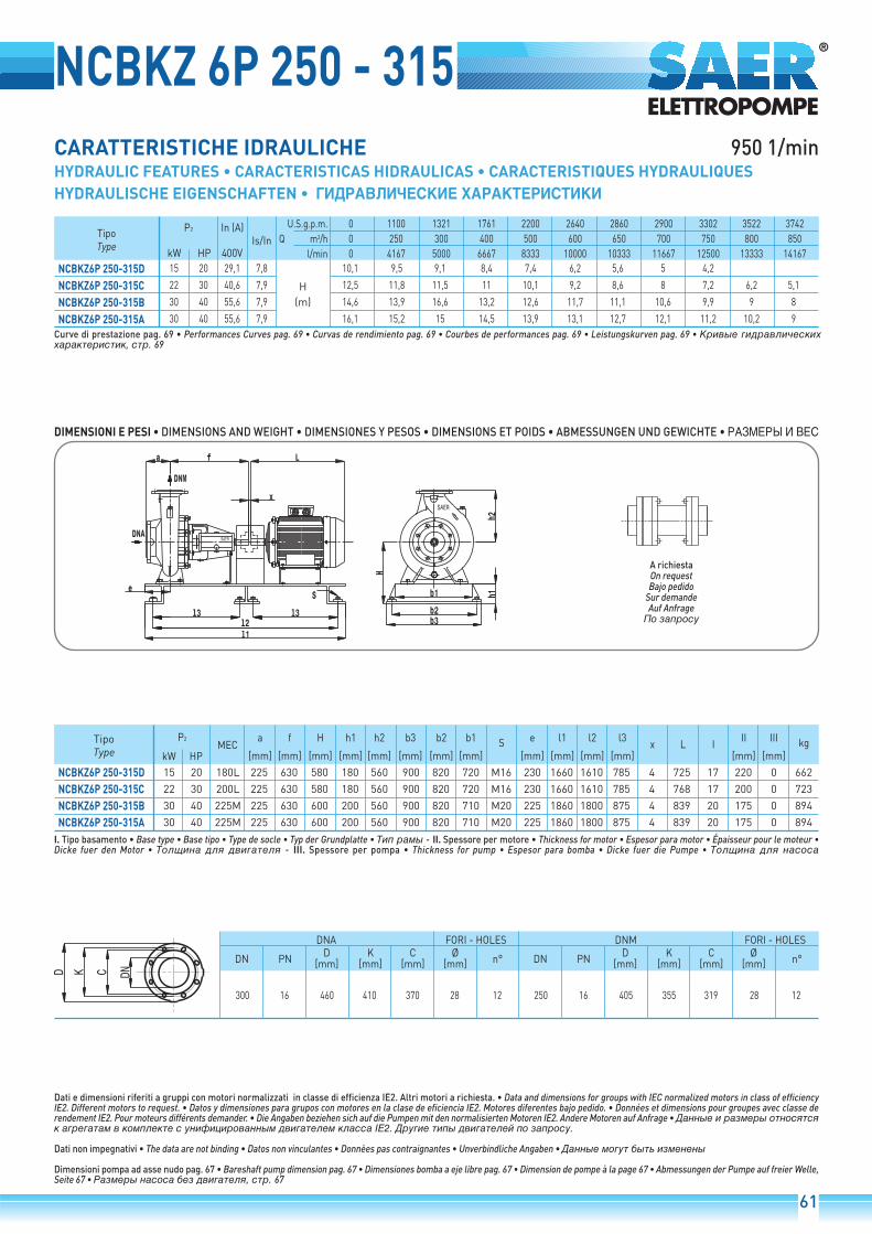
NCBKZ 6P 250 - 315950 1/min
300 16 460 410 370 28 12 250 16 405 355 319 28 12
D K C Ø[mm] [mm] [mm] [mm]DN PN
DNA FORI - HOLES DNM FORI - HOLES
n° DN PND K C Ø
[mm] [mm] [mm] [mm] n°
Tipo
Type
P2
kW HP 400V
U.S.g.p.m.
Q m3/h
l/min
0 1100 1321 1761 2200 2640 2860 2900 3302 3522 3742
0 250 300 400 500 600 650 700 750 800 850
0 4167 5000 6667 8333 10000 10333 11667 12500 13333 14167
In (A)
15 20 29,1 7,8
22 30 40,6 7,9
30 40 55,6 7,9
30 40 55,6 7,9
NCBKZ6P 250-315DNCBKZ6P 250-315CNCBKZ6P 250-315BNCBKZ6P 250-315A
10,1 9,5 9,1 8,4 7,4 6,2 5,6 5 4,2
12,5 11,8 11,5 11 10,1 9,2 8,6 8 7,2 6,2 5,1
14,6 13,9 16,6 13,2 12,6 11,7 11,1 10,6 9,9 9 8
16,1 15,2 15 14,5 13,9 13,1 12,7 12,1 11,2 10,2 9
Is/In
H
(m)
NCBKZ6P 250-315DNCBKZ6P 250-315CNCBKZ6P 250-315BNCBKZ6P 250-315A
15 20 180L 225 630 580 180 560 900 820 720 M16 230 1660 1610 785 4 725 17 220 0 662
22 30 200L 225 630 580 180 560 900 820 720 M16 230 1660 1610 785 4 768 17 200 0 723
30 40 225M 225 630 600 200 560 900 820 710 M20 225 1860 1800 875 4 839 20 175 0 894
30 40 225M 225 630 600 200 560 900 820 710 M20 225 1860 1800 875 4 839 20 175 0 894
a f H h1 h2 b3 b2 b1
[mm] [mm] [mm] [mm] [mm] [mm] [mm] [mm]
Tipo
TypeMEC
P2
kW HP
S e l1 l2 l3
[mm] [mm] [mm] [mm]x L I
II III
[mm] [mm]kg

62
950 1/min
NCBKZ 6P 250 - 400
300 16 460 410 370 28 12 250 16 405 355 319 28 12
D K C Ø[mm] [mm] [mm] [mm]DN PN
DNA FORI - HOLES DNM FORI - HOLES
n° DN PND K C Ø
[mm] [mm] [mm] [mm] n°
NCBKZ6P 250-400D 55 75 280M 225 630 200 600 600 900 820 710 M20 225 2000 1940 945 4 1035 21 120 0 1249
a f H h1 h2 b3 b2 b1
[mm] [mm] [mm] [mm] [mm] [mm] [mm] [mm]
Tipo
TypeMEC
P2
kW HP
S e l1 l2 l3
[mm] [mm] [mm] [mm]x L I
II III
[mm] [mm]kg
Tipo
Type
P2
kW HP 400V
U.S.g.p.m.
Q m3/h
l/min
0 1761 2200 2640 2900 3522 3963 4402 4843 5063 5283 5504
0 400 500 600 700 800 900 1000 1100 1150 1200 1250
0 6667 8333 10000 11667 13333 15000 16667 18333 19167 20000 20833
In (A)
55 75 99,2 7,7
75 100 129,8 7,9
75 100 129,8 7,9
90 125 153,6 8
NCBKZ6P 250-400DNCBKZ6P 250-400CNCBKZ6P 250-400BNCBKZ6P 250-400A
19,3 19,2 19 18,3 17 15,5 13,6 11,7 9,7
21,5 21,4 21,1 20,8 20 18,8 17 15,1 12,6 10,5
24,3 23,9 23,7 23,3 22,4 21,5 20 18,5 16,4 14,1 12,9
27 26,1 25,8 25,1 24,4 23,5 22,1 20 19 17,3 15,9 14,3
Is/In
H
(m)
NCBKZ6P 250-400CNCBKZ6P 250-400BNCBKZ6P 250-400A
75 100 315S 225 630 620 220 600 950 870 760 M20 230 2090 640 2020 4 1190 22 85 0 1520
75 100 315S 225 630 620 220 600 950 870 760 M20 230 2090 640 2020 4 1190 22 85 0 1520
90 125 315M 225 630 620 200 600 950 870 760 M20 230 2090 640 2020 4 1340 22 85 0 1620
a f H h1 h2 b3 b2 b1
[mm] [mm] [mm] [mm] [mm] [mm] [mm] [mm]
Tipo
TypeMEC
P2
kW HP
S e l1 l2 l5
[mm] [mm] [mm] [mm]x L I
II III
[mm] [mm]kg

63
NCBKZ 6P 250 - 500950 1/min
300 16 460 410 370 28 12 250 16 405 355 319 28 12
D K C Ø[mm] [mm] [mm] [mm]DN PN
DNA FORI - HOLES DNM FORI - HOLES
n° DN PND K C Ø
[mm] [mm] [mm] [mm] n°
Tipo
Type
P2
kW HP 400V
U.S.g.p.m.
Q m3/h
l/min
0 1761 2200 2640 2900 3522 3963 4402 4843 5063 5283
0 400 500 600 700 800 900 1000 1100 1150 1200
0 6667 8333 10000 11667 13333 15000 16667 18333 19167 20000
In (A)
90 125 153,6 8
110 150 187,1 7,7
110 150 187,1 7,7
NCBKZ6P 250-500CNCBKZ6P 250-500BNCBKZ6P 250-500A
34,8 34 33,6 33 32,2 30,9 29,2 27,1 24,9 23,6 22,3
37,8 37 36,5 35,9 35 33,8 31,7 29,5 27 25,8 24,6
42,4 41,6 41 40,5 39,5 37,8 35,6 33,1 30,3 29 27,6
Is/In
H
(m)
NCBKZ6P 250-500CNCBKZ6P 250-500BNCBKZ6P 250-500A
90 125 315M 225 720 670 220 670 990 910 820 M20 275 2270 700 2200 4 1340 25 135 0 1840
110 150 315L 225 720 670 220 670 990 910 820 M20 275 2270 700 2200 4 1340 25 135 0 1930
110 150 315L 225 720 670 220 670 990 910 820 M20 275 2270 700 2200 4 1340 25 135 0 1930
a f H h1 h2 b3 b2 b1
[mm] [mm] [mm] [mm] [mm] [mm] [mm] [mm]
Tipo
TypeMEC
P2
kW HP
S e l1 l2 l5
[mm] [mm] [mm] [mm]x L I
II III
[mm] [mm]kg

64
950 1/min
NCBKZ 6P 300 - 315
350 16 520 470 429 28 16 300 16 460 410 370 28 12
D K C Ø[mm] [mm] [mm] [mm]DN PN
DNA FORI - HOLES DNM FORI - HOLES
n° DN PND K C Ø
[mm] [mm] [mm] [mm] n°
Tipo
Type
P2
kW HP 400V
U.S.g.p.m.
Q m3/h
l/min
0 2311 2640 3522 4402 4843 5283 5724 6164 6384
0 525 600 800 1000 1100 1200 1300 1400 1450
0 8750 10000 13333 16667 18333 20000 21667 23333 24167
In (A)
22 30 40,6 7,9
45 60 81,5 7,2
NCBKZ6P 300-315CNCBKZ6P 300-315A
9,7 8,4 7,9 6,9 5,5 4,8 4 3,2
15,9 15,5 15,1 14,2 12,6 11,6 10,8 9,5 7,9 7
Is/In
H
(m)
NCBKZ6P 300-315CNCBKZ6P 300-315A
22 30 200L 300 640 625 200 600 900 820 710 M20 245 2000 1940 945 4 768 28 225 0
45 60 280S 300 640 625 200 600 900 820 710 M20 245 2000 1940 945 4 984 28 145 0
a f H h1 h2 b3 b2 b1
[mm] [mm] [mm] [mm] [mm] [mm] [mm] [mm]
Tipo
TypeMEC
P2
kW HP
S e l1 l2 l3
[mm] [mm] [mm] [mm]x L I
II III
[mm] [mm]kg

65
NCBKZ 6P 300 - 400950 1/min
350 16 520 470 429 28 16 300 16 460 410 370 28 12
D K C Ø[mm] [mm] [mm] [mm]DN PN
DNA FORI - HOLES DNM FORI - HOLES
n° DN PND K C Ø
[mm] [mm] [mm] [mm] n°
Tipo
Type
P2
kW HP 400V
U.S.g.p.m.
Q m3/h
l/min
0 1761 2640 3522 4402 5283 6164 7045 7925
0 400 600 800 1000 1200 1400 1600 1800
0 6667 10000 13333 16667 20000 23333 26667 30000
In (A)
75 100 129,8 7,9
90 125 153,6 8
110 150 187,1 7,7
NCBKZ6P 300-400CNCBKZ6P 300-400BNCBKZ6P 300-400A
19,5 19,3 19 18 16,5 14,5 12 9
23 22,8 22,5 22 20,5 18,5 16 13,5 10
26 25,9 25,8 25,7 24,8 23 21 17,8 14,5
Is/In
H
(m)
NCBKZ6P 300-400CNCBKZ6P 300-400BNCBKZ6P 300-400A
75 100 315S 300 720 670 220 670 990 910 820 M20 260 2270 700 2200 4 1190 23 135 0 1720
90 125 315M 300 720 670 220 670 990 910 820 M20 260 2270 700 2200 4 1340 23 135 0 1820
110 150 315L 300 720 670 220 670 990 910 820 M20 260 2270 700 2200 4 1340 23 135 0 1910
a f H h1 h2 b3 b2 b1
[mm] [mm] [mm] [mm] [mm] [mm] [mm] [mm]
Tipo
TypeMEC
P2
kW HP
S e l1 l2 l5
[mm] [mm] [mm] [mm]x L I
II III
[mm] [mm]kg

66
950 1/min
NCBKZ 6P 300 - 500
350 16 520 470 429 28 16 300 16 460 410 370 28 12
D K C Ø[mm] [mm] [mm] [mm]DN PN
DNA FORI - HOLES DNM FORI - HOLES
n° DN PND K C Ø
[mm] [mm] [mm] [mm] n°
Tipo
Type
P2
kW HP 400V
U.S.g.p.m.
Q m3/h
l/min
0 1761 2640 3522 4402 4843 5283 5724 6164
0 400 600 800 1000 1100 1200 1300 1400
0 6667 10000 13333 16667 18333 20000 21667 23333
In (A)
75 100 129,8 7,9
90 125 153,6 8
110 150 187,1 7,7
NCBKZ6P 300-500CNCBKZ6P 300-500BNCBKZ6P 300-500A
33,2 31 29,4 26,5 22,1 19,7 16,6 13,6 10,4
38 34,8 33,2 30,7 27,1 24,7 22,1 19,2 15,6
41,6 37,8 36,5 34,2 30,7 28,7 25,9 23,5 19,4
Is/In
H
(m)
NCBKZ6P 300-500CNCBKZ6P 300-500BNCBKZ6P 300-500A
75 100 315S 300 720 670 220 670 990 910 820 M20 275 2270 700 2200 4 1190 25 135 0 1835
90 125 315M 300 720 670 220 670 990 910 820 M20 275 2270 700 2200 4 1340 25 135 0 1935
110 150 315L 300 720 670 220 670 990 910 820 M20 275 2270 700 2200 4 1340 25 135 0 2025
a f H h1 h2 b3 b2 b1
[mm] [mm] [mm] [mm] [mm] [mm] [mm] [mm]
Tipo
TypeMEC
P2
kW HP
S e l1 l2 l5
[mm] [mm] [mm] [mm]x L I
II III
[mm] [mm]kg

67
NCBK
PD2= 4•J
NCBK 150-500NCBK 200-315NCBK 200-400NCBK 200-500NCBK 250-315NCBK 250-400NCBK 250-500NCBK 300-315NCBK 300-400NCBK 300-500
200 150 180 130 110 Ø48 530 60 400 500 110 200 150 640 500 16 140 27 51,8 14 430 299
250 200 180 105 110 Ø42 530 45 355 500 110 200 150 550 450 14 140 24 45,3 12 415 213
250 200 180 125 110 Ø55 630 40 355 500 110 250 190 630 500 14 140 27 59,3 16 465 325,5
250 200 200 130 110 Ø55 630 40 425 560 110 250 190 700 560 14 140 27 59,3 16 465 451,5
300 250 225 130 110 Ø55 630 40 400 560 110 250 190 690 560 14 140 27 59,3 16 465 345
300 250 225 125 110 Ø55 630 40 400 600 110 250 190 690 560 14 140 27 59,3 16 465 370
300 250 225 130 120 Ø70 720 60 450 670 140 250 190 810 670 14 160 30 74,9 20 550 565
350 300 300 130 110 Ø55 640 40 425 600 110 250 190 700 560 14 140 27 59,3 16 475
350 300 300 140 120 Ø70 720 60 450 670 140 315 250 810 670 14 160 32 74,9 20 550 545
350 300 300 140 120 Ø70 720 60 450 670 140 355 280 810 670 14 160 32 74,9 20 550 659,5
Tipo
TypeDNA DNM a b c d* f g h1 h2 l m1 m2 n1 n2 p r s t u w kg
d*: Ø42-Ø48 k6; Ø55-Ø70 m6
Tipo
Type
NCBK 150-500
NCBK 200-315
NCBK 200-400
NCBK 200-500
NCBK 250-315
NCBK 250-400
NCBK 250-500
NCBK 300-315
NCBK 300-400
NCBK 300-500
0,84
0,33
0,57
0,98
0,37
0,75
1,2
0,58
0,82
1,3
150 285 240 211 23 8
200 340 295 266 23 12
250 405 355 319 28 12
300 460 410 370 28 12
350 520 470 429 28 12
D K C Ø[mm] [mm] [mm] [mm]DN
DNA FORI - HOLES
n°

68

69

133
n.
NCBK 150-500 1450 1/min
DN DN200 150

n.
NCBK 200-315 1450 1/min
DN DN250 200
134

135
n.
NCBK 200-400 1450 1/min
DN DN250 200

n.
NCBK 200-500 1450 1/min
DN DN250 200
136

137
n.
NCBK 250-315 1450 1/min
DN DN300 250

n.
NCBK 250-400 1450 1/min
DN DN300 250
138

139
n.
NCBK 250-500 1450 1/min
DN DN300 250

n.
NCBK 300-315 1450 1/min
DN DN350 300
140

141
n.
NCBK 300-400 1450 1/min
DN DN350 300

n.
NCBK 300-500 1450 1/min
DN DN350 300
142

143
n.
NCBK 200-315 950 1/min
DN DN250 200

n.
NCBK 200-400 950 1/min
DN DN250 200
144

145
n.
NCBK 200-500 950 1/min
DN DN250 200

n.
NCBK 250-315 950 1/min
DN DN300 250
146

147
n.
NCBK 250-400 950 1/min
DN DN300 250

n.
NCBK 250-500 950 1/min
DN DN300 250
148

149
n.
NCBK 300-315 950 1/min
DN DN350 300

n.
NCBK 300-400 950 1/min
DN DN350 300
150

151
n.
NCBK 300-500 950 1/min
DN DN350 300

154
N. COMPONENTE COMPONENTE BAUTEIL
1
2
3
4
5
6
7
8
9
10
14
15
16
17
18
19
21
22
23
24
25
26
27
28
29
30
32
33
34
35
36
37
38
39
40
45
46
47
48
49
50
52
53
(a)
(b)
Tappo
Guarnizione
Corpo pompa
Girante
Guarnizione *
Disco portatenuta
Vite
Bussola (b)
Distanziale
Paragoccia
Coperchio cuscinetti
Cuscinetto*
Parte rotante tenuta*
Parte fissa tenuta*
Anello OR
Coperchio tenuta meccanica
Rondella
Dado
Dado e controdado
Vite
Linguetta
Albero
Linguetta
Supporto
Vite
Piede sostegno
Vite
Rondella
Tappo riempimento / sfiato (a)
Indicatore livello (a)
Rondella di spallamento (b)
Baderna* (b)
Distanziale camera stoppa (b)
Premistoppa (b)
Vite prigioniera (b)
Anello OR* (a)
Rondella (a)
Tappo di scarico (a)
Oliatore a livello costante (a) -accessorio a richiesta
Distanziale
Cuscinetto*
Anello di usura*
Vite
Versione con cuscinetti inbagno d'olio
Versione con tenuta abaderna
COMPONENT COMPOSANTIT GB ES F DE RUS
Plug
Gasket
Pump body
Impeller
Gasket *
Seal disc
Screw
Bushing (b)
Spacer
Drip tray
Bearing cover
Bearing *
Seal - Rotating unit*
Seal - Stationary seat *
O-Ring
Mechanical seal cover
Washer
Nut
Nut and lock nut
Screw
Key
Shaft
Key
Support
Screw
Support foot
Screw
Washer
Filling / Breather plug (a)
Level indicator (a)
Support washer (b)
Soft packing* (b)
Soft packing spacer (b)
Soft packing clamp (b)
Stud screw (b)
O-Ring* (a)
Washer (a)
Discharging plug (a)
Constant level oiler (a) -on request
Spacer
Bearing *
Wear rings
Screw
Oil bath bearings version
Soft packing seal version
Tapón
Guarnición
Cuerpo bomba
Rodete
Guarnición
Disco porta sello
Tornillo
Casquillo (b)
Espaciador
Paragotas
Cobertura de cojinete
Cojinete
Componente giratorio desello mecánico *
Componente fijo de sellomecánico*
O-Ring
Cobertura de sello mecánico
Arandela
Tuerca
Tuerca y cierra tuerca
Tornillo
Lengüeta
Eje
Lengüeta
Soporte
Tornillo
Pie de apoyo
Tornillo
Arandela
Tapón de ventilación yllenado (a)
Indicador de nivel (a)
Arandela de soporte (b)
Baderna* (b)
Espaciador prensaestopas (b)
Prensaestopas (b)
Tornillo prisionero (b)
O-Ring* (a)
Arandela (a)
Tapón de escape (a)
Contenedor de aceite a nivelconstante (a) bajo demanda
Espaciador
Cojinete
Anillos de desgaste
Tornillo
Versión con lubrification decojinetes baño de aceite
Versión con empaquetadurabaderna
Bouchon
Garniture
Corps de pompe
Roue
Garniture *
Plateau/couvercle porteGarniture mécanique
Vis
Douille (b)
Entretoise
Goutte-preneur
Couvercle roulements
Roulement *
Partie rotative joint *
Partie fixe joint *
Bague OR
Couvercle joint mécanique
Rondelle
Ecrou
Ecrou bas
Vis
Languette
Arbre
Languette
Support
Vis
Pied de soutien
Vis
Rondelle
Bouchon de vidange (a)
Indicateur de niveau (a)
Rondelle (b)
Presse-garniture (b)
Entretoise chambre étoupe (b)
Presse-garniture (b)
Goujon prisonnier (b)
Bague OR (a)
Rondelle (a)
Bouchon de décharge (a)
Huileur a niveau constant (a)
Entretoise
Roulement *
Bagues d'usure
Vis
Version avec roulementslubrifiés par l'huile
Version avec garniture abaderne
Stopfen
Dichtung
Pumpengehäuse
Laufrad
Dichtung * *
Scheibe/Dichtungsdeckel
Schraube
Buchse (b)
Distanzstück
Tropfschutz
Kugellagerdeckel
Lager *
Dichil *
Dichter und fester Teil *
O-Ring
Mechanisch dichter Deckel
Unterlegscheibe
Flache Mutter
Flache Mutter
Schraube
Feder
Welle
Feder
Stützplatte
Schraube
Stützfuß
Schraube
Unterlegscheibe
Ablassschraube (a)
Niveauanzeiger
Anlaufscheibe (b)
Handfdichtung (b)
Abstandhalter derStopfbuchsenkammer (b)
Stopfbuchse (b)
Stiftschraube (b)
O-Ring (a)
Unterlegscheibe (a)
Abflusskappe (a)
Oelkanne (auf Anfrage) - (a)
Distanzstück
Lager *
Verschleissringe
Schraube
Ausfuehrung mit Ölbadlager
Ausfuehrung mit Stopfbuchse
Компонент

155
(b)
(a)
NCB
K

156
IT GB ESI valori minimi di funzionamento che possono essere raggiuntiall'aspirazione delle pompe sono limitati dall'insorgere dellacavitazione.La cavitazione consiste nella formazione di bolle di vapore in un liquidoquando localmente la pressione raggiunge un valore critico, ovveroquando la pressione locale è uguale o appena inferiore alla pressionedi vapore del liquido.Le bolle di vapore fluiscono assieme alla corrente e quandoraggiungono una zona di maggior pressione, si ha il fenomeno dicondensazione del vapore in esse contenuto. Le bolle collidonogenerando onde di pressione che si trasmettono alle pareti, le quali,sottoposte a cicli di sollecitazione, si deformano per poi cedere perfatica. Questo fenomeno, caratterizzato da un rumore metallicoprodotto dal martellamento cui sono sottoposte le pareti, prende ilnome di cavitazione incipiente.I danni conseguenti alla cavitazione possono essere esaltati dallacorrosione elettrochimica e dal locale aumento della temperaturadovuto alla deformazione plastica delle pareti. I materiali chepresentano migliore resistenza a caldo ed alla corrosione sono gliacciai legati ed in special modo gli austenitici.Le condizioni di innesco della cavitazione possono essere previstemediante il calcolo dell'altezza totale netta all'aspirazione, denominatanella letteratura tecnica con la sigla NPSH (Net Positive Suction Head).L'NPSH rappresenta l'energia totale (espressa in m) del fluido misurataall'aspirazione in condizioni di cavitazione incipiente, al netto dellatensione di vapore (espressa in m) che il fluido possiede all'ingressodella pompa.Per trovare la relazione tra l'altezza statica hz alla quale installarela macchina in condizioni di sicurezza, occorre che la seguenterelazione sia verificata:
(1) hp + hz (NPSHr + 0.5) + hr + hvdove:hp è la pressione assoluta che agisce sul pelo libero del liquido nella
vasca d'aspirazione espressa in m di liquido; hp è il quoziente trapressione barometrica ed il peso volumico del liquido.
hz è il dislivello tra l'asse della pompa ed il pelo libero del liquido nella vasca d'aspirazione espresso in metri; hz è negativo quandoil livello del liquido è più basso dell'asse della pompa.
hr è la perdita di carico nella tubazione d'aspirazione e negli accessoridi cui essa è corredata quali: raccordi, valvola di fondo, saracinesca,curve, ecc.
hv è la pressione di vapore del liquido alla temperatura di esercizioespressa in m di liquido. Hv è il quoziente tra la tensione di vaporePv e il peso volumico del liquido.
0,5 è un fattore di sicurezza.
La massima altezza di aspirazione possibile per una installazionedipende dal valore della pressione atmosferica (quindi dall'altezzasul livello del mare in cui è installata la pompa) e dalla temperaturadel liquido.
Per facilitare l'utilizzatore vengono fornite delle tabelle che danno,con riferimento all'acqua a 4°C e al livello del mare, la diminuzionedell'altezza manometrica in funzione della quota sul livello del mare,e le perdite d'aspirazione in funzione della temperatura.
20 40 60 80 90 110 120
0,2 0,7 2,0 5,0 7,4 15,4 21,5
Temperatura acqua (°C)
Perdita di aspirazione (m)
Le perdite di carico sono rilevabili dalle tabelle riportate sulcatalogo. Allo scopo di ridurre la loro entità al minimo, specialmentenei casi di aspirazione notevoli (oltre i 4-5 m) o nei limiti difunzionamento alle portate maggiori, è indispensabile l'impiegodi un tubo in aspirazione di diametro maggiore di quello dellabocca aspirante della pompa.È sempre buona norma comunque posizionare la pompa il piùvicino possibile al liquido da pompare.
Esempio di calcolo:Liquido: acqua a ~20°C = 1 Kg/dm3
Portata richiesta: 50 m3/hDislivello d'aspirazione: 3 mIl valore dell'NPSH richiesto è di 3 mPer l'acqua a 15°C il termine hv risulta Pv = 0,17 m
eh = Pa = 10,33 m
Le perdite di carico per attrito hr nella condotta d'aspirazione convalvole di fondo sono ~ 1,5 m.Sostituendo i parametri della relazione1 con i valori numerici dicui sopra si ha:
10,33 + (-3) (3 + 0,5) + 1,5 + 0,17
risolvendo si ottiene: 7,33 5,17
La relazione risulta soddisfatta.
500 1000 1500 2000 2500 3000
0,55 1,1 1,65 2,2 2,75 3,3
Quota sul livello del mare (m)
Perdite di aspirazione (m)
Minimum achievable operating values by the pump suction are limitedby the onset of cavitation.Cavitation is the formation of bubbles of vapour in a liquid when localpressure reaches a critical value, that is, when local pressure is equalor just under the vapour pressure of the liquid. The bubbles of vapourflow along with the current and when they reach an area at a higherpressure, the vapour they contain condenses. The bubbles collideand generate pressure waves that are transmitted to the walls, which,subject to cycles of strain, warp and then yield due to fatigue. Thisphenomenon, with its characteristic metallic noise caused by thehammering to which the walls are subjected, is called incipientcavitation.The damage deriving from cavitation can be worsened byelectrochemical corrosion and the local increase in temperaturecaused by the plastic deformation of the walls. The materials withthe highest resistance to heat and corrosion are steel alloys, especiallyaustenites.The conditions in which cavitation begins can be forecast by calculatingthe net positive suction head (NPSH).The NPSH represents the total energy (expressed in m) of the fluidmeasured at the suction intake in conditions of incipient cavitation,net of the vapour pressure (expressed in m) possessed by the fluidat the pump intake.To find the relationship between the static head hz at which themachine can be safely installed, the following relationship must bechecked:
(1) hp + hz (NPSHr + 0.5) + hr + hvwhere:hp is the absolute pressure acting on the free surface of the liquid
in the suction tank expressed in m of liquid; hp is the quotient between barometric pressure and the volumetric weight of the liquid.
hz is the difference in level between the pump axis and the free surface of the liquid in the suction tank expressed in metres; hzis negative when the level of the liquid is lower than the pump axis.
hr is the pressure drop in the suction piping and accessories such as connectors, bottom valve, gate valve, bends, etc.
hv is the vapour pressure of the liquid at working temperature expressed in m of liquid. hv is the quotient between the vapour pressure Pv and the volumetric weight of the liquid.
0.5 is a safety factor.
The maximum possible suction head for an installation depends onatmospheric pressure (the height of the pump above sea level,therefore) and the temperature of the liquid.
Tables are provided to help users, giving, with reference to water at4°C and sea level, the decrease in the hydraulic pressure headaccording to the height above sea level, and suction drops accordingto temperature.
20 40 60 80 90 110 120
0,2 0,7 2,0 5,0 7,4 15,4 21,5
Water temperature (°C)
Suction loss (m)
Pressure drops can be identified from the tables shown in thecatalogue. With a view to reducing these as much as possible,especially in cases of considerable differences in suction levels(over 4-5 m) or at operating limits at greater rates of flow, a suctionpipe with a larger diameter than that of the pump intake mouthmust be used.The pump should always be positioned as near as possible to theliquid to be pumped.
Example of a calculation:Liquid: water at ~20°C = 1 Kg/dm3
Required rate of flow: 50 m3/hDifference in suction level: 3 mThe required NPSH value is 3 mFor water at 15°C the hv term is Pv = 0,17 m
eh = Pa = 10,33 m
Pressure drops due to friction hr in the suction duct with bottomvalve are ~1.5 m.The parameters of the relation are replaced with the abovenumerical values to obtain:
10.33 + (-3) = (3 + 0.5) + 1.5 + 0.17
which leads to: 7.33 = 5.17
The relation is satisfied.
500 1000 1500 2000 2500 3000
0,55 1,1 1,65 2,2 2,75 3,3
Height above sea level (m)
Suction losses (m)
Los valores mínimos de funcionamiento que se pueden alcanzar enla aspiración de las bombas son limitados por la aparición de lacavitación.La cavitación consiste en la formación de burbujas de vapor en unlíquido cuando la presión local alcanza un valor crítico, o sea cuandola presión local es igual o está apenas por debajo de la presión devapor del líquido.Las burbujas de vapor fluyen junto con la corriente y, cuando alcanzanuna zona de mayor presión, se produce el fenómeno de la condensacióndel vapor que contienen. Las burbujas chocan generando ondas depresión que se transmiten a las paredes, las cuales, sometidas aciclos de esfuerzo, se deforman para luego ceder por fatiga. Estefenómeno, caracterizado por un ruido metálico producido por elmartilleo al que son sometidas las paredes, adquiere el nombre decavitación incipiente.Los daños que resultan de la cavitación pueden ser exaltados por lacorrosión electroquímica y por el aumento local de la temperaturadebido a la deformación plástica de las paredes. Los materiales quepresentan mejor resistencia en caliente y a la corrosión son lasaleaciones de acero y en especial los aceros austeníticos.Las condiciones para la iniciación de la cavitación se pueden prevercon el cálculo de la altura total neta en aspiración, denominada enla literatura técnica con la sigla NPSH (Net Positive Suction Head).La NPSH representa la energía total (indicada en m) del fluido medidaen la aspiración en condiciones de cavitación incipiente, detraída latensión de vapor (indicada en m) que el fluido posee enla entrada de la bomba.Para encontrar la relación entre la altura estática hz a la que serealiza una instalación segura de la máquina, se debe verificar lasiguiente relación:
(1) hp + hz (NPSHr + 0.5) + hr + hvdonde:hp es la presión absoluta que actúa sobre la superficie libre del líquido
en el depósito de aspiración de líquido, indicada en m; hp es el cociente entre presión barométrica y volumen másico del líquido.
hz es el desnivel, indicado en metros, entre el eje de la bomba y la superficie libre del líquido en el depósito de aspiración; hz es negativo cuando el nivel del líquido es más bajo que el eje de la bomba.
hr es la pérdida de carga en la tubería de aspiración y en sus accesorios,tales como: uniones, válvula de pie, compuerta, codos, etc.
hv es la presión de vapor de líquido a la temperatura de servicio indicada en m de líquido. hv es el coeficiente entre la tensión devapor Pv y el volumen másico del líquido.
0,5 es un factor de seguridad.
La altura máxima de aspiración posible para una instalación dependedel valor de la presión atmosférica (es decir de la altura sobre el niveldel mar a la que está instalada la bomba) y de la temperatura del líquido.
Para facilitar al usuario, se suministran tablas que dan, con referenciaal agua a 4°C y al nivel del mar, la disminución de la altura manométricasegún la cota sobre el nivel del mar, y las pérdidas de aspiraciónsegún la temperatura.
20 40 60 80 90 110 120
0,2 0,7 2,0 5,0 7,4 15,4 21,5
Temperatura agua (°C)
Pérdida de aspiración (m)
Las pérdidas de carga se pueden obtener de las tablas del catálogo.A fin de reducir su entidad al mínimo, especialmente en los casosde aspiración notables (más de 4-5 m), o en los límites defuncionamiento con los caudales mayores, es indispensableemplear un tubo de aspiración que tenga un diámetro mayor queel orificio de aspiración de la bomba.De todas maneras, se aconseja colocar la bomba lo más cercaposible del líquido por bombear.
Ejemplo de cálculo:Líquido: agua a ~20°C = 1 kg/dm3
Caudal requerido: 50 m3/hDesnivel de aspiración: 3 mEl valor de NPSH requerido es de 3 mPara agua a 15°C el término hv es Pv = 0,17 m
eh = Pa = 10,33 m
Las pérdidas de carga por fricción hr en la tubería de aspiracióncon válvulas de pie son ~1,5 m.Sustituyendo los parámetros de la relación 1 con los valoresnuméricos antedichos, se obtiene:
10,33 + (-3) (3 + 0,5) + 1,5 + 0,17
resolviendo se obtiene: 7,33 5,17
La relación se ha satisfecho.
500 1000 1500 2000 2500 3000
0,55 1,1 1,65 2,2 2,75 3,3
Altitud sobre el nivel del mar (m)
Pérdidas de aspiración (m)
APPENDICE TECNICATECHNICAL APPENDIX • SUPLEMENTO TÉCNICO

ITALIANO
I valori di NPSHr indicati nelle curve caratteristiche sono valoriminimi, corrispondenti al limite della cavitazione; essi sonovalidi solamente per acqua degasata.Pertanto per motivi di sicurezza i valori riportati nelle curvedevono essere aumentati di 0,5 m. per l’impiego pratico.I valori indicati nelle curve caratteristiche sono garantiti secon-do la norma UNI EN ISO 9906 - Appendice A.
Fra le curve caratteristiche di una pompa centrifuga a varievelocità, purché non intervengano fenomeni di cavitazone, sus-siste la legge di affinità che si può esprimere nel modo seguente:Le curve Q-H e Q-P a n. giri diventano in Q’-H’ e Q’-P’ a n.’ giri.secondo:
Q’ = · Q H’ = 2
· H P’ = 3
· P
Q = Portata (m3/h)H = Prevalenza manometrica totale (m)�= Rendimento totale pompa� = Densità del fluido (Kg/dm3)P = Potenza assorbita (kW)
P = = [kW]
ADATTAMENTO DELLE POMPE A DIVERSE CONDIZIONI DI ESERCIZIOQualora la caratteristica della pompa sia diversa da quellarichiesta dall’impianto, una delle possibilità di adattamento aquesta nuova condizione si può conseguire modificando lacaratteristica della pompa mediante la riduzione del diametroesterno della girante.Il diametro a cui bisogna tornire il telaio del mozzo e dellacorona si determina ricorrendo alle leggi di affinità già prece-dentemente descritte.Pertanto la formula che ci permette di calcolare il nuovo dia-metro é la seguente:
D’ � D ·
Il diametro di tornitura si determina nel seguente modo:nel diagramma Q-H si traccia una retta che parta dal punto (O)di origine degli assi cartesiani ed intersechi il nuovo punto difunzionamento (B) e che interseca in (A) la curva relativa aldiametro D della girante.Si ottengono così i valori di H e H’ che inseriti nella formula per-mettono di ottenere il diametro di tornitura approssimativo D’.Questa relazione é valida soprattutto per le giranti radiali, qua-lora la caratteristica richiesta dovesse venire fortemente ridot-ta. É opportuno non provvedere subito alla tornitura fino alvalore calcolato D’ ma un valore del diametro di poco superio-re; provare la pompa e con la nuova curva Q-H determinare ildiametro definitivo.Tale procedimento é consigliabile quanto più elevato é il nume-ro di giri specifico della girante.
( )n’n’( )n’
n’( )n’n’
� · Q · H367 · �
H’H’
ENGLISH
The NPSHr values shown by the curves features, are minimumvalues, at the limit of cavitation; they refer only to waterwithout gas.Therefore, for a safefy reason, the values indicated in the cur-ves have to be increased of 0,5 meters for the practical use.The values shown by the curves features, are guaranteed accor-ding to UNI EN ISO 9906 standards, Appendix A.
For the curves features of a centrifugal pump at various speeds,provided that it doesn’t go into cavitation, there is an affinitylaw that is the following:The curves Q-H e Q-P at n. r.p.m. becomes Q’-H’ e Q’-P’ at n.r.p.m.:
Q’ = · Q H’ = 2
· H P’ = 3
· P
Q = Capacity (m3/h)H = Total manometric head (meters)�= Total pump efficiency� = Density of the fluid (Kg/dm3)P = Absorbed power (kW)
P = = [kW]
ADAPTATION OF THE PUMPS TO THE DIFFERENT CONDITIONS OF OPERATIONIn case the characteristic of the pump is different from the onerequested by the plant, one of the possibility of adaptation tothis new condition can be achieved by modifying the characte-ristic of the pump by reducing the external diameter of theimpeller.The measure of the diameter of the hub frame and of the plate,can be obtained with the affinity law previously explained.Therefore, the formula to calculate the new diameter D’ is thefollowing:
D’ � D ·
The turning diameter can be obtained in the following way:in the diagram Q-H, draw a straight line which starts from ori-gin (O) point of the cartesian axis and intersects the new func-tioning point (B) and that intersects in (A) the curve correspon-ding to the diameter D of the impeller.In this way, it is possible to obtain the H and H’ values which,inserted into the formula, enable to obtain the approximateturning diameter D’.This calculation is valid especially for the radial impellers.In case the requested characteristic needs to be highly reduced,it is necessary not to turn the diameter at once to the calcula-ted value D’ but it is advisable to turn it to a diameter value alittle bit higher; test the pump first and with the new curve Q-Hdeterminate the final diameter.This procedure is the more advisable the more higher is thenumber of rounds of the impeller.
( )n’n’( )n’
n’( )n’n’
� · Q · H367 · �
H’H’
Diagramma per determinare il diametro di tornitura.
Riduzione del diametro esternodella girante per pompa centrifugamediante tornitura.
Diagram to determine turning diameter.
Reduction of the external diameterof the centrifugal pump impellerby means of turning.
Heigh
t H
Rate of flow Q
ESPAÑOL
Los valores de NPSHr indicados en las Curvas de caracteristicas sonvalores mínimos, correspondientes al punto límite de cavitacíon;solamente válidos para agua sin gas en suspensión.Por eso, por seguridad, los valores expresados en las Curvas debenser aumentados a lo menos de 0,5 m. en la utilización práctica.Los valores indicados en las Curvas de Características estángarantizados según la Norma UNI EN ISO 9906 - Parrafo A.
Entre las Curvas de Características de una Bomba Centrífugacon varias velocidades, sin fenómenos de cavitación, existe laLey de Afinidad, que se puede expresar como sigue:Las Curvas Q-H y Q-P en N revoluciones se transforman en Q’-H’ y Q’-P’ en N’ revoluciones según:
Q’ = · Q H’ = 2
· H P’ = 3
· P
Q = Caudal (m3/h)H = Altura manométrica total (m)�= Rendimiento total de la bomba� = Densidad del fluído (Kg/dm3)P = Potencia absorbida (kW)
P = = [kW]
ADAPTACIÓN DE LAS BOMBAS A DIFERENTES CONDICIONES DE FUNCIONAMIENTOEn caso de que la característica de la bomba sea diferenterespecto a la requerida en la instalación, existe la posibilidadde adaptación de la misma, modificando la característica de labomba a través de la reducción del diámetro exterior delimpulsor.Se necesita tornear el diámetro del bastidor del cubo y de lacorona, según las leyes de afinidad anteriormente indicadas.Para esto, la fórmula para calcular el nuevo diámetro es laseguiente:
D’ � D ·
El diámetro de torneado se calcula de la siguiente manera:En el gráfico Q-H se traza una línea recta saliente del punto (O)de origen de los ejes cartesianos, esta se intersecta con el nuevopunto de funcionamiento (B) y se intersecta en (A) con la Curvadel diámetro (D) del impulsor. De esta manera se obtienen los valores H y H’ los cuales nospermiten obtener el diámetro de torneado aproximado (D)mediante la fórmula.Esta relación es válida sobre todo para los impulsores radiales.En el caso de que la característica requerida sea muy reducida,no es necesario tornear el impulsor hasta el valor calculado (D’)sino a un valor de diámetro un poco superior.Ensayar la bomba y con la nueva curva (Q-H) determinar eldiámetro definitivo.Este proceso se aconseja sobre todo si el número de revolucio-nes del impulsor es elevado.
( )n’n’( )n’
n’( )n’n’
� · Q · H367 · �
H’H’
Diagrama para determinar eldiámetro de torneado.
Reducción con torneado del diáme-tro exterior del rodete para bombacentrífuga.
Altur
a H
Caudal Q
158
IT GB ES

SAER ELETTROPOMPE S.p.A.Via Circonvallazione, 22 • 42016 Guastalla (RE) Italy
Tel. 0522.83.09.41 r. a. • Fax 0522.82.69.48e-mail: [email protected] - http://www.saerelettropompe.com
®
Cod
. 248
- 4
/201
2
Prestazioni e tolleranze secondo UNI EN ISO 9906 - Appendice A
Performances and tolerances according to UNI EN ISO 9906 - Attachment A
Prestaciones y tolerancias de acuerdo con UNI EN ISO 9906 - Parrafo A
Performances et tolérances conformes aux normes UNI EN ISO 9906 - Annexe A
Leistungen und Abweichungen gemäß UNI EN ISO 9906 - Anhang A
• La ditta si riserva la facoltà di modificare senza preavviso i dati riportati in questo catalogo.
• Saer can alter without notifications the data mentioned in this catalogue.
• Saer se reserva el derecho de modificar los datos indicados en este catalogo sin previo aviso.
• Saer se réserve le droit de modifier sans préavis les données techniques dans ce catalogue.
• Das Unternehmen behält sich das Recht vor, die in dem Katalog vorhandenen Daten ohne Benachrichtigung zu ändern.
SAER is an ISO 9001:2008Certified CompanyCertificate N. 501003317


