54
ELG4125: Lecture 2 Power Transformers The Ideal Transformer The Real Transformer Equivalent Circuits for Practical Transformers The Per-Unit System Three-Phase Transformers Autotransformers

ELG4125: Lecture 2
Power Transformers
The Ideal Transformer
The Real Transformer
Equivalent Circuits for Practical Transformers
The Per-Unit System
Three-Phase Transformers
Autotransformers

Transformers in Power Systems
• Typically in power systems, voltages get transformed approximately five times between generation and delivery to the users.
• Generation in power systems, primarily by synchronous generators, takes place at around 20-kV level.
• Transmission voltages of 230 kV, 345 kV, 500 kV, and 765 kV is common.
• At the load, these voltages are stepped down to 120/240 V single-phase in residential usage.
• Another advantage of transformers in many applications is to provide electrical insulation for safety purposes.

3
Transformer Types
Power Transformers
Current Transformers
Voltage Transformers
Series Transformers
Transformer Purchasing Issues
Efficiency
Audible Noise
Installation Costs
Manufacturing Facilities
Performance Record
Real Transformers
Transformer Connections
Each leg is a single phase transformer
Y-Y connections (no phase shift)
D-D connections (no phase shift)
Y-D connections (-30 degrees phase shift)
D-Y connections (+30 degrees phase shift)

Nameplate Information
• kVA is the apparent power.
• Voltage ratings for high and low side are no-load values. The symbol between the values indicate how the voltages are related:
• Long dash (—) From different windings.
• Slant (/) …from same winding: • 240/120 is a 240 V winding with a center tap.
• Cross (X) Connect windings in series or parallel. Not used in wye-connected winding:
• 240X120 two part winding connected in series for 240 or parallel for 120.
• Wye (Y) A wye-connect winding.

Basic Principles of Transformer Operation
• Transformers consist of two or more coupled windings where almost all of the flux produced by one winding links the other winding.

Transformer Exciting Current
• Transformers use ferromagnetic materials that guide magnetic flux due to their high permeability, require small ampere-turns to produce the desired flux density.
• The magnetising current is that current which flows in the primary winding when the primary voltage is applied with the secondary unloaded. It is the necessary current that satisfies the excitation condition as determined by the fundamental transformer equation.
• In modern power transformer of large kVA ratings, the magnetizing currents in their normal operating region are very small, for example, well below 0.2% of the rated current at the rated voltage.

Voltage Transformation
• The EMF of a transformer at a given flux density increases with frequency. By operating at higher frequencies, transformers can be physically more compact because a given core is able to transfer more power without reaching saturation and fewer turns are needed to achieve the same impedance. However, core loss and conductor skin effect also increase with frequency.
• Aircraft and military equipment employ 400 Hz power supplies which reduce core and winding weight. Conversely, frequencies used for some railway electrification systems were much lower (16.7 Hz and 25 Hz) than normal utility frequencies (50/60 Hz) for historical reasons concerned mainly with the limitations of early electric traction systems.
• As such, the transformers used to step down the high over-head line voltages (15 kV) were much heavier for the same power rating than those designed only for the higher frequencies.
dt
dN e v P PP
dt
d N e v SSS

• Where VP is the RMS value of the applied voltage with the assumption that eP = VP. The second Equation shows that the flux is determined by the applied voltage, the frequency of operation, and number of turns in the winding.
maxmax 4442
2 φ f N. φ f Nπ
E PPP
P
P
f N.
V
444 max

Example

Transformer Equivalent Circuit Viewed from the Primary Side

Modeling a Real Transformer

Equivalent Circuit with Parameters Moved to the Primary Side

Transformer Phasor Diagram

15
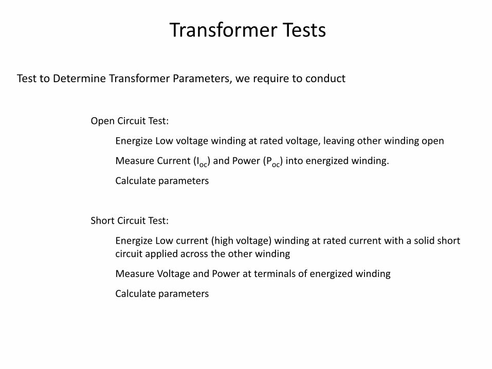
Transformer Tests
Test to Determine Transformer Parameters, we require to conduct
Open Circuit Test:
Energize Low voltage winding at rated voltage, leaving other winding open
Measure Current (Ioc) and Power (Poc) into energized winding.
Calculate parameters
Short Circuit Test:
Energize Low current (high voltage) winding at rated current with a solid short circuit applied across the other winding
Measure Voltage and Power at terminals of energized winding
Calculate parameters

Transformer Test
Open-Circuit Test
Short-Circuit Test
22
and ,
S
C
S
e
S
C
S
S
CS
C
I - I I
V
P I
Sm
SSm
SC
SSC
I
V X
I
V R
and ,2SC
SCT
I
P R
2
2
T
SC
SC
TR
I
V X -

Example 1

Example 2

The Per unit system
• In the per-unit system, the voltages, currents, powers,
impedances, and other electrical quantities are
expressed on a per-unit basis by the equation:
• It is customary to select two base quantities to define a
given per-unit system. The ones usually selected are
voltage and power.
Quantity per unit =
Actual value
Base value of quantity

ratedbVV ratedb SS
Then compute base values for currents and impedances
b
b
b
V
SI
b
b
b
b
b
S
V
I
VZ
2

b
actualup
V
VV ..
b
actualup
I
II ..
b
actualup
S
SS ..
b
actual
up
Z
ZZ
..
%100% .. upZZ

Example 1

23
Example 2
An electrical load is rated 120 volts, 500 watts. Compute
the per-unit and percent impedance of the load. Give the
per unit equivalent circuit.
Power factor = 1.0
8.28500
)120( 222
P
VR
R
VP
08.28Z

24
Select base quantities
Compute base impedance
The per-unit impedance is
VASb 500
VVb 120
8.28500
)120( 22
b
bb
S
VZ
.p.u018.28
08.28..
bup
Z
ZZ
25
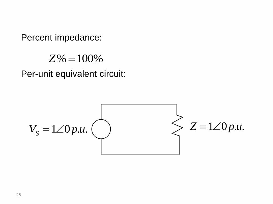
Percent impedance:
Per-unit equivalent circuit:
%100% Z
..01 upZ ..01 upVS

26
Per-unit System for Single Phase Circuits
One-phase circuits
LVbLV VV
IVSSb -1
where
neutraltolineVV --
currentlineII -
HVbHV VV
bLV
bbLV
V
SI
bHV
bbHV
V
SI

27
b
bLV
bLV
bLVbLV
S
V
I
VZ
2)(
b
bHV
bHV
bHVbHV
S
V
I
VZ
2)(
*
pupu
b
pu IVS
SS
cospupu
b
pu IVS
PP
sinpupu
b
pu IVS

28
Transformation Between Bases
Ab VV 1Ab SS 1
1
1
b
Lpu
Z
ZZ
1
2
11
b
bb
S
VZ
And second
Bb VV 2Bb SS 2
2
2
b
Lpu
Z
ZZ
2
2
22
b
bb
S
VZ

29
Transformation Between Bases
2
2
2
1
2
1
2
11
21
2
b
b
b
b
b
b
L
b
b
L
pu
pu
V
S
S
V
Z
Z
Z
Z
Z
Z
Z
Z
1
2
2
2
112
b
b
b
bpupu
S
S
V
VZZ
“1” – old
“2” - new
oldb
newb
newb
oldb
oldpunewpuS
S
V
VZZ
,
,
2
,
,
,,

30
Transformation Between Bases
Generally per-unit values given to another base can be
converted to new base by the equations:
2
11___2___ ),,(),,(
base
basebaseonpubaseonpu
S
SSQPSQP
2
11___2___
base
basebaseonpubaseonpu
V
VVV
1
2
2
2
2
11___2___
)(
)(),,(),,(
basebase
basebasebaseonpubaseonpu
SV
SVZXRZXR
When performing calculations in a power system, every
per-unit value must be converted to the same base.
31
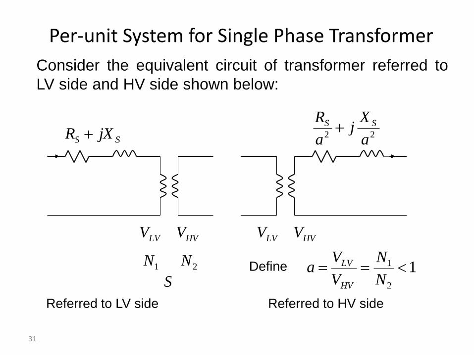
Per-unit System for Single Phase Transformer
Consider the equivalent circuit of transformer referred to
LV side and HV side shown below:
LVV HVV LVV HVV
SS jXR
1N 2N
22 a
Xj
a
R SS
Referred to LV side Referred to HV side
Define 12
1 N
N
V
Va
HV
LV
S

32
Per-unit System for Single Phase Transformer
Choose
ratedLVb VV ,1
ratedb SS
Compute
112
1bb
LV
HVb V
aV
V
VV
b
bb
S
VZ
2
11
b
bb
S
VZ
2
22
2
2
1
2
1
2
2
2
1
2
1
)1
(
a
Va
V
V
V
Z
Z
b
b
b
b
b
b

33
Per-unit System for Single Phase Transformer
Per-unit impedances are
1
1..
b
SSup
Z
jXRZ
12
1
22
2
22
2..
b
SS
b
SS
b
SS
upZ
jXR
a
Za
jX
a
R
Z
a
jX
a
R
Z
2..1.. upup ZZ

34
Voltage Regulation
%100-
-
--
loadfull
loadfullloadno
V
VVVR
Voltage regulation is defined as
%100,
,,
-
-
--
loadfullpu
loadfullpuloadnopu
V
VVVR
In per-unit system
Vfull-load: Desired load voltage at full load. It may be equal to, above, or
below rated voltage. Vno-load: The no load voltage when the primary voltage is the desired
voltage in order the secondary voltage be at its desired value
at full load.

35
Example
A single-phase transformer rated 200-kVA, 200/400-V, and
10% short circuit reactance. Compute the voltage
regulation when the transformer is fully loaded at unity
power factor and rated voltage 400-V.
PVSV1.0j
loadS
VVb 4002
kVASb 200
puS puload 01,
pujX puS 1.0,
SX

36
Rated voltage
puV puS 00.1,
pu
jj
XIVV
o
puSpupuSpuP
7.5001.1
1.011.000.100.1
,,,
puV
SI
puS
puload
puload 00.100.1
00.1**
,
,
,

37
puVV o
puPloadnopu 7.5001.1,, -
puVV puSloadfullpu 00.1,, -
Secondary side
Voltage regulation
%1.0%1000.1
0.1001.1
%100,
,,
-
-
-
--
loadfullpu
loadfullpuloadnopu
V
VVVR

38
Select Vbase in generator circuit and Sb=100MVA, compute the
per unit equivalent circuit.
Problem
G
100j
20 kV 22kV/220kV
80MVA
14%
220kV/20kV
50MVA
10%
50MVA
0.8 PF
lagging

Residential Distribution Transformers
Single phase transformers are commonly used in residential distribution systems. Most distribution
systems are 4 wire, with a multi-grounded, common neutral.
39

Three-Phase Transformers

41
Per-unit System for Three Phase Circuits
LVLbLV VV ,
IVSSSb 33 13 --
3/)(lineLneutraltoline VVV --
Lcurrentline III -
HVLbHV VV ,
LLb IVS 3
bHVbHVbLVbLVb IVIVS 33

42
Per-unit System for Three Phase Circuits
b
bLV
b
bLVbLV
LV
LV
bLVS
V
S
VV
I
VZ
2)(3
3
b
bHVbHV
S
VZ
2)(
**
3
3
3pupu
bb
LL
b
pu IVIV
IV
S
SS
bLV
bbLV
V
SI
3
bHV
bbHV
V
SI
3

43
Three 25-kVA, 34500/277-V transformers connected in D-
Y. Short-circuit test on high voltage side:
Determine the per-unit equivalent circuit of the
transformer.
Per-unit System for Three Phase Transformer
VV SCLine 2010,
AI SCLine 26.1,
WP SC 912,3
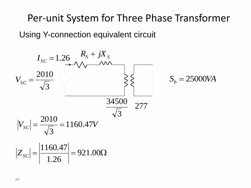
44
Using Y-connection equivalent circuit
Per-unit System for Three Phase Transformer
3
34500277
SS jXR
VASb 250003
2010SCV
26.1SCI
00.92126.1
47.1160SCZ
VVSC 47.11603
2010

45
Per-unit System for Three Phase Transformer
-- 86.90048.191921 2222
SSCS RZX
WP 3043
912 48.191
26.1
30422
SC
SI
PR
86.90048.191 jZSC
VASb 25000 VV HVb 58.199183
34500,
99.1586925000
58.19918 2
,HVbZ
pujj
Z YpuSC 0568.0012.099.15869
86.90048.191,,

46
Using D-connection equivalent circuit
Per-unit System for Three Phase Transformer
34500 277
D,SCZ
VASb 250002010SCV
3
26.1SCI
D 79.2764727.0
2010,SCZ
VVSC 2010 AISC 727.03
26.1

47
Per-unit System for Three Phase Transformer
-- DDD 30.270418.57579.2764 222
,
2
,, SSCS RZX
WP 3043
912 D 18.575
727.0
30422,
SC
SI
PR
86.90048.191 jZSC
VASb 25000 VV HVb 34500,
4761025000
345002
,HVbZ
pujj
Z puSC 0568.0012.047610
30.170418.575,,
D

Transformer Efficiency
lossout
out
in
out
P P
P
P
P
powerInput
powerOutput
θ IVP SSout cos
100
cos
cos
CCuSS
SS
P P θ IV
θ IV

Load Tap Changing Transformers
• LTC transformers have tap ratios that can be varied to regulate bus voltages.
• The typical range of variation is 10% from the nominal values, usually in 33 discrete steps (0.0625% per step).
• Because tap changing is a mechanical process, LTC transformers usually have a 30 second dead-band to avoid repeated changes to minimize wear and tear.
• Unbalanced tap positions can cause “circulating VARs;” that is, reactive power flowing from one winding to the next in a three phase transformer.
49
Phase Shifting Transformers
• Phase shifting transformers are used to control the phase angle across the transformer.
• Since power flow through the transformer depends upon phase angle, this allows the transformer to regulate the power flow through the transformer.
• Phase shifters can be used to prevent inadvertent "loop flow" and to prevent line overloads.
50

Phase Shifting Transformer Picture
230 kV 800 MVA Phase Shifting Transformer During factory testing
Source: Tom Ernst, Minnesota Power
Costs about $7 million, weighs about 1.2 million pounds
51

Power Transformers from China


Autotransformers
• Autotransformers are transformers in which the primary and secondary windings are coupled magnetically and electrically.
• This results in lower cost, and smaller size and weight.
• The key disadvantage is loss of electrical isolation between the voltage levels. This can be an important safety consideration when a is large. For example in stepping down 7160/240 V we do not ever want 7160 on the low side!
54


