SECITY CLSSSIATIOW OF IHIS PAGE __________________ __________________ PREPORT DOCUMENTATION PAGE - l1b. rESTDCITV MARI(MIGS AD A23 525w 3. DISTRIBUTbONIAVAC.AIIhJITY OF REPORtT AD-A 35 25 I~lIE'~~iIII~I~IiAPPROVED FOR PU'BLIC RELEASE Eli ~-~.: DISTRIBUTION UNLIMITED 4. PEIO1IG ORGANIZATION REMRl NUIJIIERC)5 4WOIGOGNZTONRP UI 6a. NAM Of- PER0OIMfEG ORGANIZATION 6b. OfFICE SYMBOL 7a. NAME OF MONITORING ORGANIZATION UNIVERSITY OF MINNESOTAI(fapak AESOR/NA 6C. ADDR1ESS (fty, State, and ZI Cc*e) 7b, ADDRES (Qy, Stad ZI WCode) AEROSPACE ENGINEERING AND MECHIFNICS BUILDIG 410 UNIVERSITY OF MIWNESOTA BOLLING AFB DC 20332-644 8 MINNEAPOLIS, M 55455-0129 ____________________ S&. NAME OF FUNDINGI/SPONSORING 8b, OfFFICE SYMBOL 9, PROCUREMENT INSTRUMENT IDENTIFICATION NUMBER ORGANIZAMON O ~f ) AFOSR/NA j 4 AFOSR-87-0143 8C. ADDRESS (City, Stae, and ZIP Code) 10. SOURCE OF FUNDING NUMBERS BUILDING 410 PROGRAM FROJECT TASK JWORIK UNIT BOLLING AFB DC 20332-6448 ELEMEN no NO CESSION NO. 6). 11. TITLE (Lnilude Security Classification) CRAZING IN POLYMERIC PND COMPOSITE SYSTEMS (UNCLASSIFIED) 12. PERSONAL AUTVCR(S) Dr. C. C. Hsiao, Professor, University of Minnesota, Minneapolis 13a. TYPE OF REPORT 113b. TIME COVERED 14. DATE OF: REPORT (Year Month, Day) E COUN Final Technical 1FROM 3/15/8-ko3/14/9q 1990, April, 13.PECON 16. SUPPLEMENTARY NOTATION 17 COSATI CODES 18 SUBJECT TERMS (Continue on reverse if necessary and identify by block number) FIELD I GROUP jSUB-GROUP 19. ABSTRACT (Continue on reverse if necessary and identif 4 y by Lolock number) The technical report on crazing in Dolymeric and composite systems encom- passes several phases of mesomechanics studies which lead into continuum and non-continuum microdamage mechanics investigations. Based upon the first principles-of physics and mechanics and the sciences of the microstructure of materials, this new interdiscipilinary research has been quite challenging and very fruitful. As a result new ideas have been introduced in dEveloping new theories and breakthroughs have occurred on several fronts in time dependent deformation, strength theories and damage criteria for solids and composiE systems. 20. DISTRIBUTION /AVAILABILITY OF BSTRACT 21. ABSTRACT SECURITY CLASSIFICATION MIUNCLASSIFIEDIUNLIMITED ;SAME AS RPT ODTIC USERS unclassified 22a. NAME OF RESPONSIBLE INDIVIDUAL 22b. TEL PHONE~ George K. Haritos, Lt. Col., USAF ( 2 0M) 7 6 yf 4 Sjt Irea Cd) I22c,.OFFIE OL DO FORM 1473, 84 MAR 83 APR edition may be used until exhausted. SECURITY CLASSIFICATION OF 7H15 PAGE - -. . All other editions are obsolete. I 91 4 26 02i 6'
Transcript
SECITY CLSSSIATIOW OF IHIS PAGE __________________ __________________
6a. NAM Of- PER0OIMfEG ORGANIZATION 6b. OfFICE SYMBOL 7a. NAME OF MONITORING ORGANIZATIONUNIVERSITY OF MINNESOTAI(fapak AESOR/NA
6C. ADDR1ESS (fty, State, and ZI Cc*e) 7b, ADDRES (Qy, Stad ZI WCode)AEROSPACE ENGINEERING AND MECHIFNICS BUILDIG 410UNIVERSITY OF MIWNESOTA BOLLING AFB DC 20332-644 8MINNEAPOLIS, M 55455-0129 ____________________
S&. NAME OF FUNDINGI/SPONSORING 8b, OfFFICE SYMBOL 9, PROCUREMENT INSTRUMENT IDENTIFICATION NUMBERORGANIZAMON O ~f )AFOSR/NA j 4 AFOSR-87-0143
8C. ADDRESS (City, Stae, and ZIP Code) 10. SOURCE OF FUNDING NUMBERSBUILDING 410 PROGRAM FROJECT TASK JWORIK UNIT
BOLLING AFB DC 20332-6448 ELEMEN no NO CESSION NO.
6).11. TITLE (Lnilude Security Classification)
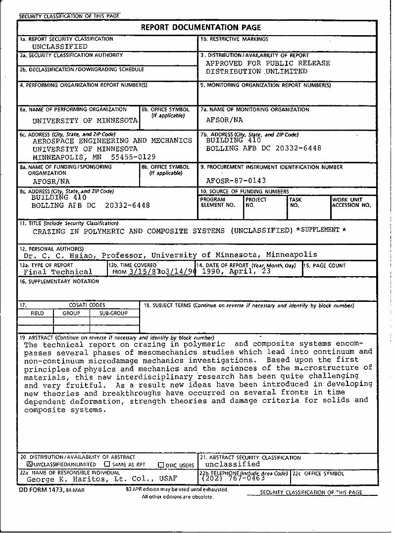
CRAZING IN POLYMERIC PND COMPOSITE SYSTEMS (UNCLASSIFIED)
12. PERSONAL AUTVCR(S)Dr. C. C. Hsiao, Professor, University of Minnesota, Minneapolis
13a. TYPE OF REPORT 113b. TIME COVERED 14. DATE OF: REPORT (Year Month, Day) E COUNFinal Technical 1FROM 3/15/8-ko3/14/9q 1990, April, 13.PECON
16. SUPPLEMENTARY NOTATION
17 COSATI CODES 18 SUBJECT TERMS (Continue on reverse if necessary and identify by block number)FIELD I GROUP jSUB-GROUP
19. ABSTRACT (Continue on reverse if necessary and identif4y by Lolock number)The technical report on crazing in Dolymeric and composite systems encom-passes several phases of mesomechanics studies which lead into continuum andnon-continuum microdamage mechanics investigations. Based upon the firstprinciples-of physics and mechanics and the sciences of the microstructure ofmaterials, this new interdiscipilinary research has been quite challengingand very fruitful. As a result new ideas have been introduced in dEvelopingnew theories and breakthroughs have occurred on several fronts in timedependent deformation, strength theories and damage criteria for solids andcomposiE systems.
20. DISTRIBUTION /AVAILABILITY OF BSTRACT 21. ABSTRACT SECURITY CLASSIFICATIONMIUNCLASSIFIEDIUNLIMITED ;SAME AS RPT ODTIC USERS unclassified
22a. NAME OF RESPONSIBLE INDIVIDUAL 22b. TEL PHONE~George K. Haritos, Lt. Col., USAF ( 2 0M)7 6 yf4 Sjt Irea Cd) I22c,.OFFIE OL
DO FORM 1473, 84 MAR 83 APR edition may be used until exhausted. SECURITY CLASSIFICATION OF 7H15 PAGE- -. . All other editions are obsolete. I
91 4 26 02i 6'
Crazng in Pokmeric: and Comosie Syslems - Fnal ,echnkal Report. Apdl 23. 1M0
CRAZING IN POLYMERIC AND COMPOSITE SYSTEMS
Table of Contents
I . Introduction .............................................................................. 2
Il. Background information and objectives ......................................-...............
III. Micromechanics of polymers and composites ............................................... 4
IV. Progress during the first year-publication .................................................. 8
V. Progress during the second year-publications --------------------------------------------- 8
1. "Analysis of Crack-Induced-Craze in Polymers" .................................. 82. "Analyzing Polymer Crazing as Quasifracture" ..................................... 9
3. 'Time Dependent Fracture Strength of Solid Bodies" ............................. 9
4. 'Temperature Variation During Polymer Failure" .................................. 105. "A New Generalized Damage Criterion for Polymers" ........................... 10
VI. Progress during the third year-research and publications .............................. 11
1. "A New Damage Criterion for Composites" ........................................ 112. "Kinetic Strength of Solids" .......................................................... 12
3. "Analyses of Three-Dimensional Crazing in Polymers" .......................... 15
4. "Crazing as Damaging Behavior of Irradiated Polymers" ......................... 27
5. "Propagation of Crack-Induced-Crazing in Unidirectional Coml. "(sites" ....... 30
VII. Current research dbvelopment and possible future impact .................................. 33
1. "A New General Unified Strength Theory and Damage Criterion forAnisotropic Solids and Composite Systems" ....................................... 34
2. "Significance of Critical Energy Theory for Damage of Anisou'opic Solidsand Composite Systems" .............................................................. 43
3. "Mechanical Strength and Damage of Polymers and Composites" ............... 44
4. "Computer Model for Amorphous Polystyrene" ................................... 48 or.
DT "
3U~'. £Ii]t r__
Avq11ability C ce
,vspa1 /
PAGESARE
MISSINGIN
ORIGINALDOCUMENT
Crazing in Polyneric and CorVosite Systems Final iechnical Repod. Apil 23. 1990
i. introduction
The study of an important and challenging problem in science and engineering has been the
understanding of the strength and fracture behavior of stressed solid systems. This is particularly
true of failure behavior and its prediction in viscoelastic material systems. Both the structural and
functional application of these materials demand a better understanding of their behavior and failure
mechanisms. When sufficiently large tensile stresses are associated with these materials, various
modes of damage develop. To elucidate these, one common mode of response, namely crazing
under an applied simple stiess, must first be understood.Major advances and breakthroughs in the
crazing behavior in microscopic and macroscopic levels of understanding will yield tremendously
useful information not only theoretically but also practically. Considerable technological and
scientific significance is attached to this :oposed endeavor. The initiation and propagation of
crazing as quasifracture, the time dependent fracture strength of oriented polymers, the associated
molecular orientation and ultimate strength in and around a craze, and the interaction of crazes in
polymeric and composite systems are just some of the features to be understood. The determination
of the time dependent fracture strength of polymers and composite systems, the displacement field
and the stress distribution in the vicinity of craze-crack transition regions as well as the propagation
behavior of craze and crack are important problems to be solved prior to the consideration of many
other relevant topics. Currently a firm foundation has been established. It appears that continued
research in the relevant outgrowth topics will result in a truly fruitful understanding of the subject
matter and lead into future fundamental investigations in mesomechanics, the connection between
microstructure and mechanics.
II. Background information and objectives, with references
Advanced reinforced plastics, consisting of a polymer matrix and fibres, continue to generate great
interest in their application to high performance structural components. Fracture of these composite
2
Crazing in Polymeric and Composite Systems Final ,echnical Report. April 23. 1990
systems may result from flaws in fibres or matrix as well as the failure of the bonds. Thus the
strength of any such composite is governed by the time dependent strength characteristics of the
matrix, the fibres and the bonds. Because of the difference in the mechanical behavior of the three
constituents of composites, up to now many strength criteria have been considered and developed
by scientists and engineers all over the world as reflected by, for example, several recent references
[1-3].
The studies of time-dependent failure of composites have been relatively scarce in spite of
the strong dependence of the failure characteristics on time. The formulation of the models must
now be based upon the microstructural peculiarities of deformation, the molecular orientation,
temperature and time [4-6]. Aside from the phenomenological models, perhaps, statistical models
[7-9] should also be considered concurrently so that they may reinforce each other's findings and
development.
References
1. Handbook of Composites Series (Strong Fibres, Structure and Design, Failure Mechanicsof Composites and Fabrication of Composites). Edited by A. Kelly and Y. N. Rabotnove,North Holland (1985).
2. Proceedings of International Symposium on Composite Materials and Structures. Edited byT. T. Loo and C. T. Sun, Beijing, China (June, 1985).
3. M. F. Kanninen and C. H. Popelar. Advanced Fractures Mechanics. Oxford UniversityPress, New York; Clarendon Press, Oxford (1985).
4. A. S. Krausz and H. Eyring. Deformation Kinetics. Wiley-Interscience, New York,London, Sydney, Toronto (1975).
5. C. C. Hsiao -nd W. Chen, A Constitutive Representation of Inhomogeneous PolymericSystems, in Polymer Networks, Structural and Mechanical Properties. Plenum Press, NewYork, London, 395 (1971).
6. C. C. Hsiao and S. R. Moghe, Characterization of Random Micro-structural Systems, inProceedings of the International Conference on Structure, Solid Mechanics andEngineering Design in Civil Engineering Materials, Part II (Southampton, England). JohnWiley, London, 1203 (1971).
3
Crazing in Polyneric and Contposite Systems Final, echnical Report, Ap il 23. 1990
7. W. Chen and C. C. Hsiao, Nonlinear Viscoelastic Constitutive Behavior as a StatisticalDynamic System, in Advances in Polymer Science and Engineering, Plenum Press, NewYork, London, 115 (1972).
8. D. R. Axelrad. Micromechanics of Solids. Elsevier Scientific Publishing Co., Amsterdam,Oxford, New York; PWN: Polish Scientific Publishers, Warszawa, 1978.
9. D. R. Axelrad. Foundauios of the Probabilistic Mechanics of Discrete Media. PergamonPress: Oxford, New York, Toronto, Sydney, Paris, Frankfurt, 1984.
Ill. Micromechanics of polymers and composites
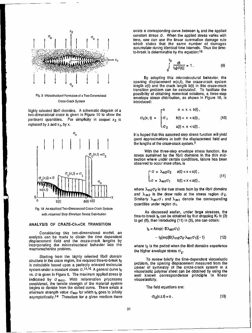
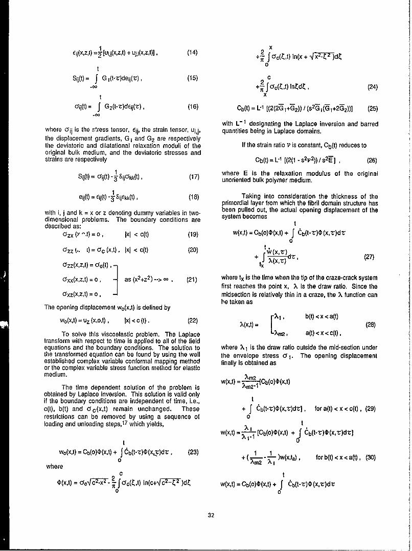
The phenomenon of crazing and its relation to some fractre analyses are considered as follows:
The formation of a craze comes about from a physical transformation in the deformation
processes of the microscopic material molecules under tensile stress. The transformation takes
place from a homogeneous deformation to a craze configuration when a critical condition is
reached. Subsequently, the craze boundary propagates as a function of applied stress, time,
temperature, physical and chemical influences as well as the actual microstructural changes
subjected to geometrical constraints. As a result, usually minute voids are generated among
oriented molecules and the density of the medium in the crazed region is nonuniformly reduced
whereas the bulk of the homogeneous material body deforms more uniformly. The interface
boundary layer enveloping crazes of many solid materials is capable of being drawn and
transformed into bundles of highly oriented molecular domain structure in the craze region. Further
stressing will eventually initiate craze-crack transition. It appears necessary to take these physical
variations into consideration in any mathematical modeling and formulation in analyzing the
stresses from the time when crazes incept to the time when they propagate and transform into real
fractures.
The science of crazing, a quasifracture state, and subsequent cracking, a fracture state, of
solid material systems under tension has been making large strides in the recent past. The crazing
mechanism has been associated with molecular orientation and fracture strength [1 to 5].
4
CrazinQ in Polymeric and Coniposlte Systems Final iechnical Report, Av, A, 1990
Subsequently various methods have been utilized to determine and confirm the molecular
mechanism with respect to craze formation and fracture in thermoplastics [5, 6]. Essentially under
tensile stresses certain solid materials deform from sites where high stress concentrations are
created and crazes develop. Because of geometrical constraints and energy requirements, the
material molecules orient themselves in the direction of stressing with voids among them. As stated
earlier, the presence of oriented polymeric molecules in a craze region bounded by surprisingly
smooth interface layers is visualized as an actual physical phase transformation in the deformation
processes from one orientation state to another depending upon the magnitude and rate of applied
tensile stress [8], material characteristics as well as, of course, temperature and physical and
chemical environments, etc., surround the solid body. As a result, the mechanical behavior of the
material is greatly affected by the macroscopic geometry and the distribution and interaction of the
individual crazes as well as the microscopic molecular configuraion and voids within each craze
region and along its immediate boundaries enveloping the area. Macroscopically the development
of crazes and their distribution can be detected statistically by laser diffraction techniques [9]. The
geometry of an individual craze which can be studied by focused laser beams [10] is of primary
importance in understanding the processes of its initiation and propagation as well as the
deformation, quasifracture-fracture transition, and eventually the fracture behavior of the medium.
Knowledge of craze initiation and geometry helps in determining the craze displacement field, the
stress distribution and the craze-crack transition and propagation under load [11, 12]. An eventual
understanding of the true mechanism of molecular strength and fracture behavior of a simple solid
matrix and a complex composite system can be obtained if fundamental microscopic information is
utilized in macroscopic analyses.
In a craze the highly strained molecular bundles act as boundary tractions with great
strength; any governing mathematical formulation must include this feature for any adequate
analysis. Crazes of different forms and properties have occurred in polymeric materials (13, 14]
5
Crazing in Polymeric and Composite Systems Final i echnical Report, April 23. 1990
and other solid systems including even single crystals [15]. An analysis is highly aesirable and
may be useful for studying general solid systems.
Both long- and short-range programs may be considered. It appears fruitful that emphasis
be placed on the study of micromechanics of individual craze-crack transition, the scurce of failure
under various internal and external stresses for the matrix and the composite systems.
The nature of the stresses in and around a craze-crack transition region is the key to the
understanding of the morphology and nucleation as well as the propagation of crazes and cracks.
The first attempt in calculating the state of macroscopic tensile stress field in the direction of the
applied load as a function of craze length has been based upon a model with an assumed craze
boundary displacement as a crack opening in an infinite elastic sheet [16]. The stresses were
calculatdd as though the craze were a continuum and the craze boundary developed no stress
perpendicular to the direction of applied stress. The solution of the two-dimensional-homogeneous
biharmonic equation for a semi-infinite elastic medium due to the application of an external
pressure to the surface has been used [17, 18]. This implies that the craze behavior is independent
of the craze medium [18, 19] under stress. The solttions were obtained using a Fourer transform
technique [20] or a complex variable method of analysis [19, 21, 22]. With proper assumed
boundary conditions the latter method of approach gives probable stress and displacement fields
surrounding a craze. A model for craze growth has also been considered with the creep of craze
material as the cause of craze propagation. The craze growth was found to be linear with respect to
the log of time [19].
The aforementioned stress analyses have been made essentially on the basis of the classical
elasticity theory for a homogeneous elastic medium with either an assunmed stress distribution for
certain portions of a crack without considering any time dependency.
:: i 'i ' iII 1 IFIP" I'- 'lr~ "t "'.'x..'v---'Lv~''''--:o'j''j''' ... " " I
Craz n in Polymeric and Composite Systems Final i echnical Report, Apil23. 1990
The development of crazing is not only a function of stress but also a function of time [23,
24]. Using th current theory and by taking into consideration the isotropic and anisotropic material
constants the mathematical model describing the crazing mechanism have been successful [25-29].
References
1 J. A. Sauer, J. Marin and C. C. Hsiao, J. App!. Phys. 20, 507 (1949).
2. C. C. Hsiao and J. A. Sauer, J. App!. Phys. 21, 1071 (1950).
3. C. C. Hsiao, J. Appl. Phys. 30, 1492 (1959).
4. C. C. Hsiao, Section IV in Fracture Processes in Polymeric Solids, Interscience, JohnWiley, 529 (1964).
5. S. R. Kao and C. C. Hsiao, J. Appl. Phys. 35, 3127 (1964).
6. S. Rabinowitz and P. Beardimore, CRC Critical Reviews in Macromolecular Science 1,(1972).
7. R. P. Kambour, J. Po!y Sci-Macromolucular Reviews 7, 1 (1973).
8. R. W. Tr:u- and G. A. Chadwick, J. Mat. Sci. 11, 1385 (1976).
9. C. C. Hsiao, Appl. Phys. Lett. 23, 20 (1973).
10. C. C. Hsiao, J. Appl. Phys. 48, 1168 (1977).
11. A. P. Wilczynski, C. H. Liu and C. C. Hsiao, J. Appl. Phys. 47, 4301 (1976).
12. A.P. Wilczynski, C. H. Liu and C. C. Hsiao, J. Appl. Phys. 48, 1149 (1977).
13. H. H. Kausch and M. Dettenmaier, Polymer Bulletin 3, 565 (1980).
14. M. Dettenmaier and H. H. Kausch, Polymer Bulletin 3, 571 (1980).
15. X. F. 14s and Z. Z. An, J. Appl. Phys. 55, 95 (1984).
16. A.C. Knight, J. Polymer Sci. 3A, 1845 (1965).
'7. H. C. Kxernz. Relationships Between Structure and Micromechanics of Solvent Crazes inGlassy Polymers, Ph.D. thesis, Cornell U.'-iversity, 115 (January, 1977).
18. N. Verineulpen-Heymans, J. Polymer Sci. Phys. 14, 93 (1976).
19. N. Verheulpen-Heymans and J. C. Bauwens, J, Mat. Sci. 11, 7 (1976).
20. B. D. Lauterwasser and E. J. Kramer, Philo. Bull. 3, 565 (1980).
7
Crazing in Polymeric and Cor,,posite Systems Final echnical Report, April23, 1990
21. N. I. Muskelishvili, Some Basic Problems of the Mathematical Theory of Elasticity, P.Noordhoff Groningen, 333 (1953).
22. T. Y. Fan, Foundations of Fracture Mechanics (in Chinese), Jiangsu Scientific andTechnical Publisher, Jiangsu (December, 1978).
23. S. S. Chem and C. C. Hsiao, J. AppI. Phys. 52, (10) 5994 (1981).
24. S. S. Chem and C. C. Hsiao, J. Appl. Phys. 53, (10) 6541 (1982).
25. S. S. Chem, Z. D. Zhang and C. C. Hsiao, J. Poly. Sci. Phys. 23, 2579 (1985).
26. C. C. Hsiao and S. R. Moghe, Characterization of Random Microstructural Systems,Proceedings, International Conference on Structure, Solid Mechanics and EngineeringDesign in Civil Engineering Materials, Southampton, England, 1969, John Wiley,London, Part I, 95 (1971).
27. V. S. Kuksenko and V. P. Tamuzs, Fracture Micromechanics of Polymer Materials,Martinus Nijhoff Publishers, 202 (1981).
28. S. S. Chem and C. C. Hsiao, J. Appl. Phys. 53, 6541 (1982).
29. Z. D. Zhang, S. S. Chern and C. C. Hsiao, J. AppI. Phys. 54, 5568 (1983).
IV. Progress during the first year-publication
A paper on "Noncontinuum Craze-Crack Transition" by C. C. Hsiao was presented at the 1988
Annual Meeting of ASME, Boston and published in Damage Mechanics in Composies-AD-I
Vol. 12 (Eds. A. S. D. Wang and G. K. Haritos), (Book No. G00376).
V/. Progress during the second year-publications
1. "Analysis of Crack-Induced-Craze in Polymers", by B. N. Sun, H. S. Houand C. C. Hsiao, published in Eng. Fracture Mechanics 30, 595 (1988).
The analysis of the crack-induced-craze in polymers is believed to be a fairly general phenomenon
in fracture studies. This work will deal with the use of a viscoelastic boundary element method for
analyzing a polymer quasi-fracture. A time dependent boundary stiffness will be considered and
the viscoelstic solution in the time domain may be obtained by applying the collocation Laplace
inversion technique. Using these methods, the quasifracture problem with tine dependent stiffness
fractions in a two-dimensional case may be analyzed. Both the craze opening displacement profile
8
Crazing in Polymeric and Corsposite Systems Finat , echnical Report, April 23, 1990
and the envelope stress distribution around a craze can be computed. This will pave the way in
evaluating the propagation history of both the crack and the craze. Results thus obtained may be
compared with those obtained by previous considerations such as the use of the Dugdale model
and the concern on the stress concentration phenomenon.
2. "Analyzing Polymer Crazing as Quasifracture", by B. N. Sun andC. C. Hsiao, published in J. Polymer Science, Phys. 26, 967 (1988)
Before any real fracture develops under stress in polymeric or composite systems, it seems that, in
a fairly general picture common to most solid systems, crazing incepts first. Following the
previously state craze-crack transition and crack-induced-craze, the initiation of crazing is simply
a special case. In the absence of crack the craze as quasifracture has been studied by many
scientists. Since the boundary element method has become recently a powerful technique for
solving boundary value problems including some nonlinear ones, it is especially important as a tool
to be used in problems having viscoelastic deformations and fractures. Therefore, it may be fruitful
in developing proper procedures for calculating the stress distributions around a craze envelope.
3. "Time Dependent Fracture Strength of Solid Bodies", by 0. M. Ettorneyand C. C. Hsiao, published in J. Appi. Phys. 64, No. 10, Part 1, 4884(1988)
Statistical theories in fracture kinetics constitute a very important role in investigating the fracture
strength of solids and their utilization in modem engineering. In this short report, a review of some
of the recent concepts and models is provided. The main concern is the effect of the breaking stress
on the time-to-break. Based upon the consideration of the fraction of integrity of a medium, a
number of models have been evaluated and compared. Two basic considerations used for
evaluation and comparison are Zhurkov's empirical kinetic relationship and Hsiao's statistical
absolute reaction rate model. Other considerations reducible from these two are also given for
comparison. Using a well-known numerical analysis method, it appears that the nonlinear
mathematical consideration is more realistic in describing the time-dependent fracture strength
9
Crazing in Polymeric and Comp)osite Systems Final , echnical Report, April 23, 1990
behavior of a medium over any linear ones. The computed results seem to fit reasonably well with
the general observations.
4. "Temperature Variation During Polymer Failure", by C. C. Hsiao andY. S. Cheng, published in Europhysics Conference Abstracts, 20th
% Europhysics Conference on Macromolecular Physics and 3rd LausannePolymer Meeting on Physical Mechanisms in Polymer Failure,(Lausanne, Switzerland) Vol 12J, September (1988)
This paper attempts to discuss the temperature variation during polymer failure using a statistical
absolute reaction rate theory. At fracture, the temperature may increase or decrease depending upon
a quantity named fraction of integrity f and its rate f and accelerator f as well as a stress modifier
P .
For over a century, scientists and engineers have observed temperature variations during
loading and testing of solids. Most work in this area focused on metallic systems: temperature
changes during elastic and/or plastic deformations, as well as theoretical investigations based on
mechanics and thermodynamics.
Using the statistical absolute reaction rate theory, the present work attempts to analyze the
temperature variation during polymer failure.
5. "A New Generalized Damage Criterion for Polymers" by C. C. Hsiao,published in Europhysics Conference Abstracts, 20th EurophysicsConference on Macromolecular Physics and 3rd Lausanne PolymerMeeting on Physical Mechanisms in Polymer Failure, (Lausanne,Switzerland) Vol 12J, September (1988)
Since the dawn of human culture, the problem of strength of solids has been experienced and
utilized empirically. Probably not until the past 500 years has the problem of strength and
deformation of solid bodies been investigated quantitatively. The phenomena of yielding and
strength have been carefully considered during the past 100 years. It is only during the last twenty
years that special attention has been given to the study of craze initiation criteria of polymers by
Sternstein and Ongchin (1969), Gent (1970), Bowden and Oxborough (1973), and Argon et al.
10
Crazing in Polymeric and Corrfosite Systems Final technical Report, April 23, 1990
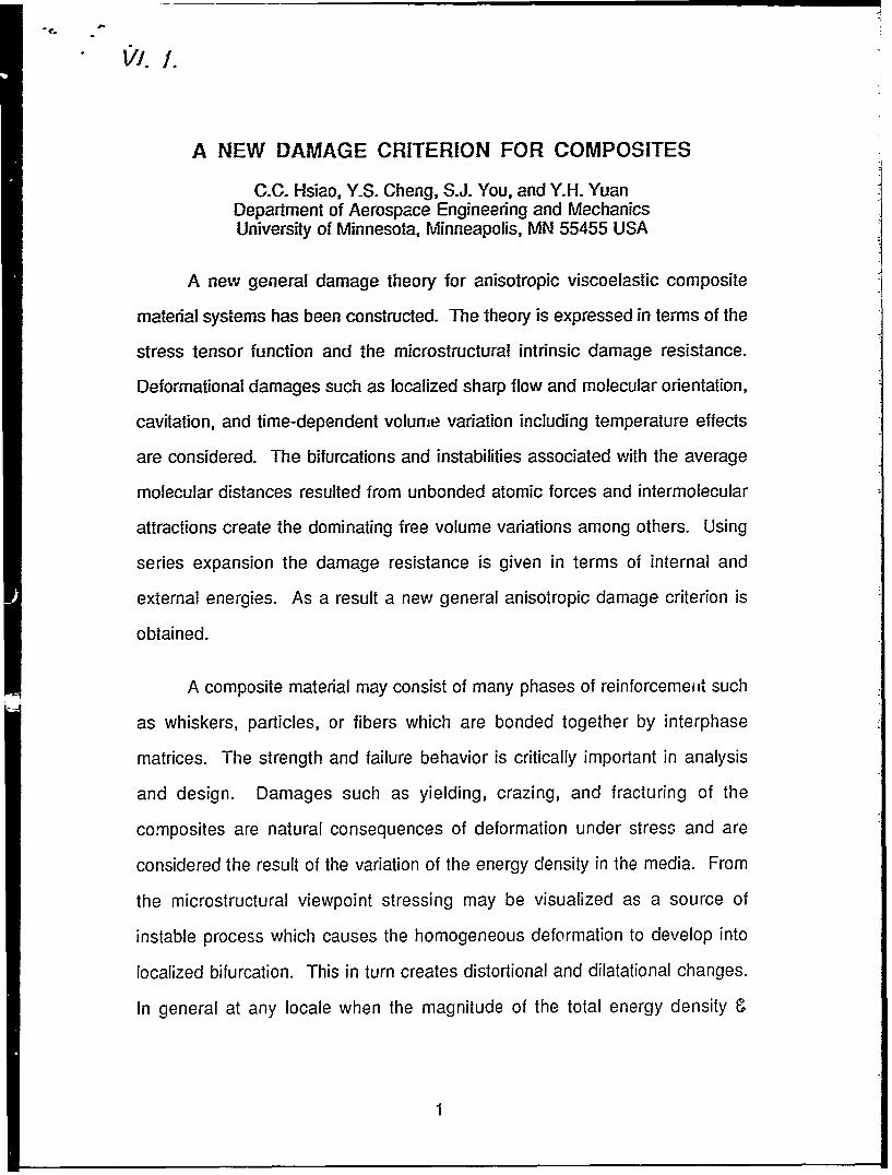
volume variations among others. Using series expansion the damage resistance is given in terms of
internal and external energies. As a result a new general anisotropic damage criterion is
constructed.
2. "Kinetic Strength of Solids", C. C. Hsiao, Advances in Fracture Research,Proceedings of the Seventh International Conference on Fracture (ICF7),2913 (1989)
The time dependent kinetic strength of solids has been studied for over half a century. In general,
two levels of approach have been employed. One is submicroscopic atomic consideration and the
other may be referred to as supermacroscopic continuum investigations. The latter is mostly
phenomenological which results in numerous empirical relationships. One of the most extensive
experimental investigations is that done by Zhurkov [1]. Under a state of constant stress creep
condition more than 50 different kinds of solids including metallic and nonmetallic, amorphous and
crystalline, oriented and unoriented systems were recorded the stress dependent of the time-to-
break data. Even data on the temperature variations were tested and analyzed. It was found that the
logarithm of time-to-break and the applied uniaxial tension were linearly related as
tb = to exp[(U -'y)/kT] (1)
where
tb is time-to-break,to is a constant,U is a constant which may be related to the activation energy of the solid,y is a positive definite constant,a is the applied constant stress,k is the Boltzmann constant andT is the absolute temperature.
However, in reality, there is deviation from this empirical linearity when either super high
stresses or relatively low stresses beyond the meso-stress range is encountered.
12
Crazing in Polymeric and Comoosite Systems F'mal, ech al Rewoo. AMi 23. 1.=--O
This short report is to address this point using an equation derived from the Tobolsky-
Eyring-Hsiao expression [2]. Essentially, the theory is based upon considerations at a
submicroscopic atomic level. At !his level, the statistical nature of any system behavior can be
calculated according to the rates of forming and breaking of bonds. To make it easily accessible to
engineering applications, the mathematical model used is a matrix of oriented submicroscopic
bonds randomly distributed in an arbitrary domain. The fraction of intact bonds "f' measures the
degree of integrity of the system. The integrity or strength of a solid body is identified by
calculating f, the rate of change of f, as follows:
f = Kr(-f) - Kbf (2)
where
Kr is the rate of reformation of broken bonds.Kb is the rate of breaking of intact bonds.
These rates can further be expressed in terms of the following submicroscope quantities:
Kr =O) exp(- U/RT- pWt, (3)
Kb =COb exp(- U/RT + 3). (4)
where
(or is the frequency of motion of the broken bonds,U is the activation energy,R is the universal gas constant,T is again the absolute temperature,p is a positive definite stress modifier,M' is the stress in the bonding direction,otb is the frequency of motion of the intact bonds and3 is a positive definite stress modifier.
13
Crazn in Po.kume and Convasile Systens Fial ,edmical Revoi. A.a 23. 1i9so
It would be interesting to compare the high kinetic strengths with experiment valule Up to
now little or no data have been found yet However, it is felt that expression (2) should predict the
kinetic strength benavior adequazely.
As stated, Zhurkov's model was and is an enmpiical relationship where s the present model
is based upon submicroscopic atomic as well as molecular considerations. It is also quite apart
from Hoff's [3] or Kachanov's [4, 5] models. Using an atomistic approach, the current model
should not be looked upon as a one-dimensional model as it is easily extended to a three-
dimensional situation by introduction of a molecular orientation mechanism as a result of
deformation [6]. This mesomechanics approach is considered to be very sound as it makes the
connection between microstructure, micromechanics, and macromechanics. Therefore the kinetic
strength is given in terms of the basic atomic and molecular quantities, so that the mechanical
properties can be deduced for solids exhibiting creep, diffusion, or dislocation glide and so on as
the time, temperature, molecular motion, and elementary bonding stresses, etc. have been
i,,orporated into the model in the first place [7, 8, 9].
References
1. Zhurkov, S.N. (1965). Kinetic concept of the strength of solids. Int. J. Frac. Mech. 1,311.
2. Krausz, A.S. and H. Eyring. (1975). Deformation Kinetics. John Wiley, New York, p.349.
3. Hoff, N.J. (1953). The necking and rupture of rods subjected to constant tensile loads. J.Appl. Mech. 20, No. 1, 105.
5. Kachanov, L.M. (1958). On the time of fracture under creep conditions. Jzv. AN SSSR.Oid. teckn nauk. 8, 26.
6. Mun, M.S. and C.C. Hsiao. (1986). Time dependent fracture strength of orientedpolymers. J. Appl. Phys. 60, 2655.
7. Hsiao, C.C. (1964). Molecular orientation-dependent fracture strength. Fracture processesin Polymeric Solids, Chap IVC, p. 529.
14
Crazi in Polme.ic and Conosie S.sr.ms Fnal ecukl Report. Aml 23. 19=0
8. Hsiao, C.C. and S.R. Moghe (1971). Characterization of random micro-structuralsystems. Proc. In. Conf. in Stracture, Solid Mechanics, and Engineering Design in CivilEngineering Materials, Parr L (Southampton, England). p. 95. John Wiley, London.
9- Ettorney, O.M. and CC. Hsiao (1988). Time dependent fracture strength of solid bodies.J. Appl. Phys. 64, 4884 (1988).
3. "Analyses of Three-Dimensional Crazing in Polymers -- in preparationfor publication
Polymers and polymeric composites usually fail by first developing crazing on the surface of the
material system. Internal crazes can also be initiated when sufficient and necessary conditions
exisL The time-dependent craze failure prccess, whether two-dimensional or three-dimensional,
may be characterized by several stages: deformation, development of microporosity, craze
initiation, craze-crack transition and propagation until complete failure occurs. The interrelationship
among the applied stress, craze initiation, time and temperature has been established and a fairly
general time-dependent theory on craze initiation in viscoelastic media has been formulated.
In 1982, C. C. Hsiao et al proposed and analyzed a two-dimensional craze growth on
surface of polymeric materials. It gave information on the time-dependent nature of craze growth in
viscoelastic media. In many actual cases of damage, however, the craze growth in a polymer is of
3-dimensional nature. But till now it does not seem that there is any work available in the literature
describing time-dependent 3-dimensional crazing-cracking behavior in polymers.
To gain a better understanding for the craze behavior in polymers, here in this report an
analysis for the time-dependent crazing in polymers is developed. The analytical work is divided
into two parts. In the first part of this report, a "DISK" model of the 3-dimensional craze is
proposed, and then a complete set of governing equations is given on the basis of viscoelastic
principles, energy theorem and variational considerations. Basic time dependent unknown
functions are the craze envelope stress (CZES), craze opening displacement (CZOD) and craze
radius (CZR). Using the variational considerations, conditions for admissible envelope stresses
(CZES) are given by singularity analysis of the stresses at the craze tip. In the second part, an
15
Crazin o in Polymeric and Conosle Svstems Firal ,echnical Re ort. Arwil 23. 193
important class of craze growth, i. e. "self-similar" solutions is proposed and considered. In this
case, any unknown field, say w,, is not considered to be directly related to the polar radius r and
time t, but only with one variable, r/c(t), here c(t) is the craze radius at time L Thus, mathematical
simplifications could be obtained in the treatment of the quadrature of the basic equations with
complexity and nonlinearity. The complicated basic equations are reduced to a single nonlinear
ordinary differential equation for the craze growth. Analytic expressions are obtained for the craze
opening displacements in terms of elliptical integrals of the first and second kinds.
Two types of simple viscoelastic media, i. e., the Maxwell and '. ,igt solids have been
considered. Numerical quadrature is used to evaluate the integral expressions containing elliptic
integrals. The nonlinear equations are solved by Runge-Kutta method numerically, to obtain the
craze opening displacements (CZOD).
Computed 3-dimensional results of craze growth are also compared with those of two-
dimensional cases.
Introduction
The study of craze initiation and growth has lasted around four decades since the first paper given
by C. C. Hsiao and J. A. Sauer in 1950 [1]. Some questions and concerns related to the
understanding of the crazing problem may be stated as follows:
a. For polymers under a set of given conditions will craze occur [2,3,4] ?
b. What are the temperature and time effects on craze initiation and growth [5-9,20] ?
c. How to model the real process of crazing behavior in polymers [9-14] ?
The knowledge obtained from crazing research is important in predicting the durability of plastics
and polymeric engineering components. Besides the theoretical approach in modelling and
16
Crazino in Pollri-c and Contoos-1e Systems Final , echn-fcal Resort. AMril 23, ISO
analyzing the craze growth, certain other experimental work has also been reported [15-23]. In
studying the craze growth processes, many different models have been considered and analyzed.
Knight [11] has proposed a craze critical initiation stress in the local craze tip area. When the local
tensile stress reaches this critical level, crazing is produced. This model gives rate insensitive craze
initiation which contradicts to the experimental observations [15,16]. Heymans et al [12] presented
a craze model, in which craze was divided into two zones with the polymer inside the craze as
being deformed plastically and outside as elastic. The results show that the craze length increases
as a logarithmic function of time, in agreement with their experimental data on polycarbonate.
Chem and Hsiao [14] analyzed a two-dimensional craze in which the viscoelastic behavior of the
bulk polymeric medium and the nature of molecular orientation within the craze region are taken
into account. Based upon this time-dependent viscoelastic model, both craze opening
displacements and craze length extensions have been computed. To obtain a better understanding
on crazing in a polymeric medium, a time-dependent theory and analysis of craze growth in
viscoelastic solids is given in the present report to elucidate the fundamental mechanism of a 3-
dimensional crazing behavior in polymers.
In this report, the work is divided into two parts. The first part is concerned with a 3-
dimensional DISK model of the time-dependent craze growth. A complete set of governing
equations and solutions are developed on the basis of viscoelasticity theory [24], energy theorems
and variational considerations. Basic unknown functions are the time-dependent craze envelope
stress (CZES), craze opening displacement (CZOD) and craze radius (CZR). Using the variational
methods, the admissible conditions for the craze envelope stress are given by singularity analysis
of the stress at the craze tip. In the second part, the complex nature of the mathematical equations is
discussed and the self-similar solutions have been proposed. Important mathematical
simplifications are obtained in the treatment of the quadrature of the basic equations for the craze
size. Analytic expressions in terms of elliptical integrals are also obtained for the craze opening
displacements [25].
17
Crazina in Polymeric and Connxsite Systems Final technical ReDort. Anril 23. 1990
Two types of simple viscoelastic media: i. e., the Maxwell and Voigt solids are considered.
Numerical quadrature is used to evaluate some integral expressions containing elliptic integrals in
their integrand appearing as parameters in solving the nonlinear ordinary differential equation for
crazing by Runge-Kutta method [26]. The craze opening displacements. (CZOD) are then
computed. Results are compared with those for the two-dimensional cases.
A 3-dimensional DISK model of craze
To deal with the analysis of a 3-dimensional craze growth problem, it is desirab!e to consider the
following DISK model as shown in Fig. 1 and Fig. 2:
In the above figures and below, the following notations are used:
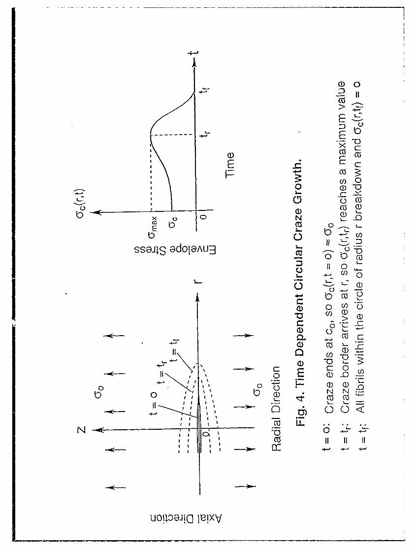
c(t): Radius of the craze at time t
w(r,t): Craze opening displacement at r and time t
d(r,t): Diameter of fibril bundle domain at rt in a craze(yc(r,t): Craze envelope stress at r,t(Yf(r,t): Stress of fibril domain at r,tVf(r,t): Volume fraction of fibrils in a craze at r,t
GO(t): Remote applied stress at t
N(rt): Number of load bearing fibril per unit craze area
Wm(r,t): Thickness of primordial layer from which fibril domain is drawn out
wo(r,t): Equals to w(r,t)-wm(r,t)
Figs. 1 and 2 describe a 3-D symmetrical craze in a simple stress field co. In the craze region,
oriented molecular fibrous bundles and voids are formed. Surrounding the craze region there is the
viscoelastic bulk polymer. The fibril connections are load bearing which can take stress af(r,t). The
craze envelope stress ac(r,t) is an average engineering stress which may be calculated by dividing
the applied force with the volume containing both the fibrils and the voids. Based upon
experimental observations, an idealized craze structure is composed of cylindrical fibrils domains
of diameter d(r,t), which may vary from position to position. During crazing process, the diameter
18
E~ C:
o 0-
I---0
ON
C) ca
IN LL
i105Oa-
0
00
o c
a)-0NC
1 - cu-C)n ca4-0
:-'-/:4-'
w 0
E I
I -m
N "--r
El
i0
Caigin Pal' imerc and Corniosite Svs'emi? Fial i echnir2!lj1--. Amil 23. Ir490
of each fibril domnaip. chatjoges with finne a~s its length changes. The craze fibr.ils re for med by
conitinuous drawing firom the unoriernted bulk polymer. This drawing process causes mass to flow.,
fromi parent phase (unoriented bulk polym~er); into new phasi: (highly oriented fibrils). The general
state of stress in the bulk polymner is expressed by a(rz,t) as shown in Fig.2. 111t is easily seen that
the volume fraction of fibrils in a craze Vf(r-,t) can be ex-pressed by c(r,t)fc Kr,t). in Fig. 1, the
fibril density distribution N(r,t) is defined as the number of load bearing fibrils passing through a
unit craze area at r,t. Permitting some possible fibrils breakdown under high loading conditions
from time to time, the function N(rt) is considered time dependent.
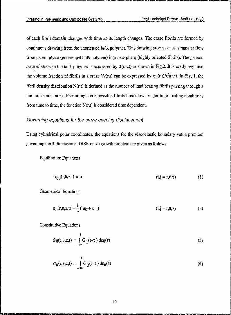
Governing equations for the craze opening displacement
Using cylindrical polar coordinates, the equations for the viscoelastic boundary value probiemi
governing the 3-dimensional DISK craze growth problem are given as follows:
Equilibrium Equations
GYj'j(r,O,z,t) = 0 (i~J = rO'z) (1),
Geometrical Equations
ejj(r,o,z,t) = I ( ui.,j+ uj;i) (i~j = rG'z) (2)
Constitutive Equations
tSij (r,oxzt) f G I (t-) deij (r) (3)
-00
taYjj(r,O,z,t) =f G2(t-x dEjj(tr) (4~
-019
Crazina in Polymeric and Composite Systems. Final i echnical Report, April 23. 1990
ij (ij =r,0,z) (5)
1
eij = eij- 3 jkk (6)
where (r,e,z) are the cylindrical polar coordinates and t is time.The symbol ";" means co-variant
differentiation. aij, ejj are stress and strain tensors respectively, and ui are displacements. S j,e,
are deviatoric stress and strain tensors, 8ij is the delta symbol and G I(t), G2(t) (t >o) are
respectively the deviatoric and dilatational moduli of the bulk polymeric media.
To complete the boundary value problem, the following boundary and initial conditions are
9. H. H. Kausch et al, Polym. Bull. 3, 565, (1980)
10. M. Dettenmair et al, Polym. Bull. 3, 571 (1980)
11. A. C. Knight, J. Polym. Sci. A3, 1845 (1965)
12. N. V. Heymans et al, J. Mater. Sci. 11, 7 (1976)
13. A. S. Argon et al, Phil. Mag. 36, 1193 (1977)
14. S. S. Chem and C. C. Hsiao, J. Appl. Phys. 53 (10), 6541 (1982)
15. A. Robinson et al, J. Appl. Phys., 31, 1602 (1960)
16. C. C. Hsiao, J. Polym. Sci. 44, 71 (1960)
17. M. I. Bessonov et al, Sov. phys. Solid state, 3, 950 (1961)
18. G. Biglione, Proc. Int. Conf. Fract. 2, 503 (1969)
26
C.C)
0
00100
NW
co I
l
-- 0- - -- - - --- - - -c
Qz >
0
Ca
(U)
10 10
LL
Ce)
00
C\j
0
co
/ / Ca)
'3)3
(DD
0)0
m 02) -0
0 0~
qi6ua-l aejo POGz!1luwJON 00/0 LL
CC,,
0 0
0Th 0
CC~)
oo" 0Lo45O 0ZOP~lWO
Crazing in Polymeric and Coi,posite Systems Finai .e chnical Report, April 23,_1990
attempt is made here to observe and characterize the behavior of polymers under simultaneous
irradiation and stress conditions. The results obtained from this approach can be combined with
those from chemical and other relevant experiments to formulate a better and broader explanation
and description of the physical process undergone by polymers when exposed to stress and
irradiation. In order to achieve a model description of the phenomenon under these conditions the
physical process of crazing, which has been known about for more than thirty years [11-13], will
be emphasized in the light of earlier work on craze initiation [14], propagation [15], and energy
absorption of crazing [16].
Exposure of polymers to irradiation results in a number of physical and chemical changes,
either temporary or permanent. Polymers can undergo one or more of the following processes:
cross-link, depolymerization, evolution of gases, change in color and/or change in crystallinity.
Among these, degradation and cross-linking are fundamentally important, because these processes
strc.gly affect the mechanical properties of the polymer, The behavior of a polymer depends
directly upon its molecular weight and chain entanglement. The variation of the aforementioned
processes can take place simultaneously. However, the ratio between the changing rates depends
on the structural configuration of the polymer, the nature of the substance present in the system and
the type of irradiation energy.
Both the degradative and cross-link processes originate from an initial bond breaking
reaction which occurs as a result of the absorption of the influential wavelength of electromagnetic
radiation. In the case of degradation, the initial reaction may represent the total extent of damage or
it may be the prelude to a series of secondary bonding reactions leading to further scission,
recombination or substitution of bonds. However, in the case of cross-linking, the process leads
to the formation of three-dimensional network structures.
As for the role of mechanical action at the atomic level, electron spin resonance
spectroscopy has graphically demonstrated that stretching, grinding, milling or any type of
28
CrazinQ in Polymedc and Cowposite Systems Finai ,echnical Report, April 23, 1990
polymer shearing process can also produce free radicals as a result of the fracture of the main chain
of the polymer [17, 18].
This article devotes special attention to the study of the craze density development and craze
propagation in samples subjectedto simultaneous irradiation and mechanical action. Results are
them compared with those found earlier in samples subjected to mechanical action only.
By piecing together the results and observations obtained thus far, a paper is being
prepared for possible publication in the future.
References
1. B. Ranby and J. F. Rabek, Photodegradation, Photo-oxidation and Photostabilization ofPolymers: Principles and Applications, Wiley-Interscience, New York (1975).
3. D. L. Allara and W. L. Hawkins, eds., Stabilization and Degradat;.on of Polymers, Adv.Chem. Ser. 169 (1978).
4. Longterm Properties of Polymers and Polymeric Materials, Appl. Polym. Symp., 35(1979)
5. A. Davis and D. Sims, Weathering of Polymers, Applied Science Publishers Ltd., London(1983).
6. N. S. Allen, ed., Developments in Polymer Photochemistry, vol.2, Applied SciencePublishers Ltd., London (1982).
7. F. A. Makhlis, Radiation Physics and Chemistry of Polymers, John Wiley & Sons, NewYork (1975).
8. A. D. Jenkins, Polymer Science, vol. 2, North-Holland Publishing Co. (1972)
9. T. Fukushima, Durability Build. Mater., 1(4), 327-343 (1983).
10. K. Sh. Bocharov, Y. S. Stroilov, V. F. Udovenko and M. V. Zinov'ev, Probl. Prochn.,(11), 108-10 (1976)
11. C. C. Hsiao and J. A. Sauer, J. Appl. Phys. 21, 1071 (1950)
12. S. Rabinowitz and P. Beardmore, Crit. Rev. Macromol. Sci. 1, 1 (1972)
13. R. P. Kambour, J. Polym. Sci. D.7, 1 (1973)
29
Crazing in Polymeric and Composite Systems Final iechnical Report, April 23. 1990
14. S. S. Chem and C. C. Hsiao, J. Appl. Phys. 57(6) (1985)
15. Z. D. Zhang, S. S. Chem and C. C. Hsiao, J. Appl. Phys. 54(10) (1983)
16. S. S. Pang, Z. D. Zhang, S. S. Chem and C. C. Hsiao, J. Polym. Sci. 23, 683-693(1985)
17. J. Shoma, Dev. Polym. Deg. 2, 99 (1979)
18. G. Scott, Adv. Chem. Ser. 169, 30 (1978)
19. S. S. Chem, Z. D. Zhang, and C. C. Hsiao, J. Polym. Sci. 23, 2579-2597 (1985)
5. "Propagation of Crack-Induced-Crazing in Unidirectional Composites"
This paper is in preparation for publication.
The paper deals with the propagation of a crack-induced craze which bisects a
unidirectional lamina of composites into two regions with orthotropic viscoelastic properties. This
complex crack-induced crazing problem has been separated into two modes: normal mode and
shear mode. Using the superposition principle and the Fourier transform technique, the associated
elasticity solution has been obtained for the determination of the time-dependent crack and craze
propagation velocities (t) and (t), employing the elasic-viscoelastic and Laplace inversion
technique numerically. It is interesting to find that the crack propagation will be arrested if the
initial crack length ao is less that a critical length ac. The viscoelastic properties of the composite
matrix is considered. The crack-induced crazing displacement at any point on the envelope surface
and the propagation history have been calculated numerically for two viscoelasticity model
matrices: Maxwell linear model matrix and generalized Kelvin model matrix.
It is well-known that the strength of a lamina composite is much greater than that of a single
matrix material of the same geometry. But the strength of individual lamina in a laminate varies
over a wide range. In many cases the composite structure will contain a number of weak sheets.
These weak lamninae will fail first due to craze-crack transition and subsequent crack-induced
crazing. As a result, the load-bearing capability of the composite may be greatly reduced
30
Crazing in Polymeric and Coinposite Systems Final echnical Report. April 23, 1990
Therefore, it is significant to investigate the crack-induced crazing in a single lamina which
contains an initial crack after craze initiation and craze-crack transition. Because of the
development of minute voids and the orientation of the polymer molecules in front of the crack tip,
craze is induced; thus it is referred to as crack-induced craze. On the other hand, the matrix
material of the composites, such as epoxy resin, is a typical time-dependent viscoelastic medium,
and so is the lamina. In this case both the stresses and the displacements are time-dependent, as
the are functions of the viscoelastic properties. Obviously it is important to study the time-
dependent crack-induced craze propagation.
However, in the past twenty years, most analyses of crack-induced craze growth
considered only the time-independent behavior of the stresses and strains. G. C. Sih [1]
considered the unidirectional composites as homogeneous anisotropic or nonhomogeneous
isotropic elastic media, and applied his criterion of minimum energy density for studying the crack
propagation. This is linear elastic fracture estimation only; the rate of crack-induced craze
propagation cannot be predicted. Some other scientists did consider the time-dependent crack-
induced craze propagation: for example, McCartney [2, 3] applied the linear isotropic viscoelastic
model to study the crack propagation and Schapery [4] developed the study of crack growth in
nonhomogeneous viscoelastic media for normal crack mode. However, these results still could not
be applied to the composite materials because the lamina of composites usually consist of
anisotropic viscoelastic media and each cracking lamina should be represented by a complex
fracture mode composed of a combination of normal and shear modes.
Experimental results revealed that the rate of crack propagation can be modified
significantly by controlling resin properties [5] in composite materials. Therefore the fracture
characteristics of the matrix are controlling parameters in crack-induced craze for aligned composite
materials. Some scientists thought that the crack propagation might be dependent upon the
polymer yield strength beyond the crack tip [6]. In that case, the Dugdale model of fracture was
borrowed to consider the propagation of crack in polymers [7]. However, it appears that the
31
Crazing in Polymeric and Composite Systems Final iechnical Report, April 23, 1990
Dugdale model is unlikely to be suited for studying the quasifracture problem of polymers because
new phases are created as a result of molecular orientation and many bundles of fibril domains are
usually found beyond the crack tip in the matrix of the composite. Such Fibril structure of the
craze beyond the crack is the feature that distinguishes it from other localized fracture in metals.
The small fibril domains, which can range from 5 to 50 nm in diameter, are loadbearing members
of the craze. Embedded in voids, the fibril domains can break down to form larger voids causing
crack propagation until fast fracture ensures [8-11]. The stress distribution along the envelope of a
craze has been successfully considered as simple step functions [12-14]. Using this crack-induced
crazing model together with energy criteria the propagation rate of cracking and crazing along the
fiber direction of a composite is studied in the present work.
For most composites there exists an angle between the fiber and the load direct. The crack-
induced crazing is a complex quasi-fracture. Some experimental work [15, 16] has shown that the
crack-induced craze propagation in a lamina is located in the matrix between the fiber domains
originated from initial d-fects such as voids or other flaws. Based upon these experimentally
observed failure models, this paper is directed toward the analysis of the lamina composite
consisting of a crack-induced craze formation in a sheet having orthotropic viscoelastic properties.
The crack-induced crazing of finite length is situated in the matrix and parallel to the fiber domains.
That means the unidirectional composite contains an initial crack-induced craze surrounded by
orthotropic viscoelastic materials. The analysis is separated into two parts: one dealing with the
normal mode and the other, the shear mode. An integral transform technique is used to reduce the
problem to the solution of dual integral equations. Then applying the superposition principle and
Laplace inversion technique, the associated elasticity solution in the Laplace domain has been
obtained and correspondingly the stress distribution, the crack and craze opening displacement
have been inverted into the real time domain. According to the universal energy rate balance, the
crack and craze growth rates (t) and c(t) in the unidirectional composite material have been derived
and calculated numerically.
32
Crazingj in Polymeric and Composite Systems Final technical Report, April 23, 1990
References
1. G. C. Sih, Fracture of composite materials, Proceedings of the First USA-USSRSymposium on Fracture of Composite Materials. Sizthoff and Noordhoff 111 (1979)
2. L. N. McCartney, Int. J. of Fracture 13, 641 (1977)
3 L. N. McCartney, Int. J. of Fracture 14, 547 (1978)
4. L. N. McCartney, Int. J. of Fracture 14, 293 (1978)
5. P. J. Hogg and D. B. P. F. Hull, 13th Reinforced Plastics Congress, Brighton 29 (1982)
6. S. Yamini and R. J. Young, J. Mat. Sci. 14, 1609 (1979)
7. W.-C. V. Wang and E. J. Kramer, J. Mat. Sci. 17, 2013 (1982)
8. C. C. Hsiao, J. Appl. Phys. 23, 1189 (1952)
9. C. C. Hsiao, Nature. 186, 535 (1960)
10. C. C. Hsiao and S. R. Moghe, Characterization of Random Micro-structural Systems, inProceedings of the International Conference on Structure, Solid Mechanics andEngineering Design in Civil Engineering Materials, Part I (Southampton, England). JohnWiley, London, 95 (1971).
11. E. J. Kramer, Polym. Eng. Sci. 24, 76 (1984)
12. S. S. Chern and C. C. Hsiao, j. Appl. Phys. 53, 6541 (1982)
13. Z. D. Zhang, S. S. Chern and C. C. Hsiao, J. Appl. Phys. 54, 5568 (1983)
14. E. H. Andrews, Duvelopment in Polymer Fracture-i, Applied Science Publishers Ltd.,London (1979)
15. M. A. Biot, Proceedings of the Fourth Midwestern Conference on Solid Mechanics 94(1955)
16. Zvi, Hashin, AIAA Journal 4 No. 8 1411 (1966)
VII. Current research development and possible future impact
As a natural outgrowth several ;mportant phases of research have been considered and preliminary
breakthrough investigations have been made. It appears that very fruitful results are forthcoming.
33
Crazin in Pomeric and Cointosie Systerns Finai .echrdcal Remit. Au 23. 19
1. "A New General Unified Strength Theory and Damage Criterion forAnisotropic Solids and Composite Systems"
Preliminaries
Using an energy approach, the concept of a new general unified strcngth theory and damage
criterion is put forward. The total critical energy, including distortional and dilatational energies,
must be overcome for damage initiation in any solid or composite systems. Using variational
principles, the extremum critical energy is obtained with respect to the specific mean free volume of
the microstructural material system. An application of the calculus of variations yields a differential
equation identifying the specific mean free volume variation of a material system as a function of
time-dependent microstructural parameters. Solutions of the differential equation will yield the
energy required for damage initiation in anisotropic solids and composite systems.
However, if the total energy representing the intrinsic damage resistance function is given
simply in terms of a series, a general time-dependent expression can be easily established.
Eigenvalues of specific mean free volume and eigenfunctions of extremum energy quantities are
obtainable. Damages by yielding, crazing and/or subsequent fracturing are associated with these
energy quantities. The new general theory can be reduced to most existing individual prominent
strength theories and damage criteria for time-independent material systems.
The damage mechanism of material systems under stress may be associated closely with
shear deformation, molecular orientation, and microcavitation. From th,. microstructural
viewpoint, stressing may be visualized as a source of energy which develops an instable process,
causing the field of homogeneous deformation to develop into localized flow and cavitation
characteristics. Thus, the creation of microcavities and the formation of micromolecular slippage
and orientation occur in regions as crazes. This bifurcation creates variations of the vacant spaces
or the free volume, in contrast to the volume occupied by atoms and molecules, and sharp flow
which is provided by the existence of loading and the available work done to the material system.
34
Crazh. in Po v..'zc and Coawose Svstens Final echdnicJ Re oit. Awl 23. 1%1k)
As a resulh, the compatibility condition for a continuum analysis breaks down. This non-
continuum behavior creates singularities. The transition from a homogeneous to non-
homogeneous state must be taken into consideration in the analysis if the strength and damage
behavior of the solid systems is to be better understood-
It is the purpose of this paper, based upon mesomechanics and energy considerations for
material systems, to develop new concepts and new governing equations in terms of eigenvalues-
eigenfunctions appropriate to different given conditions. Since the emphasis is placed on time-
dependent solid and composite systems, a few words on polymeric glass transition, the
thermodynamic aspect of the glassy state, and the equation of state of the material may be relevant.
In this study dimensional changes of polymeric matter are important. There are many
factors which can cause the dimensional change of matter. Among the most important ones are
temperature, mechanical stresses, materials structure, and the effects of time. Then physical
phenomena such as the formation of voids and crazes during mechanical deformation, fracture
initiation and propagation, and shape changes are second order transitions. Most of these changes
are related to the variation of volume. In certain situations, when a medium is in an equilibrium
state, its volume can be expressed by an equation of state which describes the dependence of the
volume on several other state variables. However, in the solid state the properties of a material,
including the volume, may depend on external stresses and temperature. Their path and time
dependency is intimately tied to specifying the degree of precision of the specific free volume used
in analyses. Nevertheless, the behavior of the specific free volume has served well in describing
the equilibrium and quasi-equilibrium transitions for amorphous polymeric systems.
While the concept of specific free volume is still qualitative, it has been useful in explaining
many properties and phenomena for polymers in their glassy state. Based upon the consideration
of the effect of time, the specific volume of a material may be written as:
35
Crazir in Polyameric and Comoosite Systems Final technical Report. Aril 23. 1990
S current volume - original volumeSpecific Volume -original volume
where the current volume is the volume measured at time t and the original volume is that
deteimined at original time to. The current volume at time t equals the vacant space or the free
volume plus the actual volume occupied by atoms and molecules at time t. Thus the specific
volume may be written as:
actual volume + free volume - original volumeoriginal volume
where the actual volume is not considered to vary greatly with respect to stress, temperature, and
time. This is particularly true when a polymer is below its glass transition temperature. This
means that the actual volume is essentially a constant. Then the variation of the specific vacant
space or free volume can be approximated by the variation of the specific volume. That is, in
dealing with the volume change, the specific free volume can be used approximately in place of the
specific volume. Therefore the specific free volume is considered in the analysis. The term
specific free volume is preferred because it characterizes and dominates the internal microscopic
damage behavior of a material system whether it be simultaneously due to microstructural
distortion or dilation or both as an internal state variable. In dealing with time-dependent
mesomechanics it may be convenient to employ the term specific mean free volume in a
mesodomain in any kinetic analyses where various degrees of free volume variation can occur, and
it may be satisfactory to consider their average information.
General Approach on Strength Theory and Damage Criterion
Using the stress tensor components a1,, the magnitude of the total energy is expressible for
an anisotropic state of stressing in terms of an anisotropic tensor Bij:
36
Crazing in Polymeric and Comoosite Systems Final i echnical Report. April 23. 1990
e=Bij(,ij. l
At any locale in a medium, when the magnitude of this energy is greater than or equal to a critical
value Cc (i.e. P >_ Cc), damage will develop. Here Cc is seen as an intrinsic damage resistance
associated with the non-uniform and non-gradual behavior of yielding, crazing and/or subsequent
fracturing, representing, among many others, distortional and/or dilatational changes.
The intrinsic damage resistance is dependent upon the intermolecular forces and in turn the
intermolecular and interatomic spacings. The average intermolecular distance may be related
closely to the specific mean free volume, characterizing this distance. Hence it may be useful to
consider the critical energy as an intrinsic damage resistance function of the specific mean free
volume.
(2)
where V is the specific mean free volume, a dimensionless quantity identifying the variation of the
specific mean free volume in a small domain in a given medium. Assuming this is accurate
enough, then to a first approximation, it may be adequate to establish a fairly general theory of
strength and damage initiation criterion for material systems in the following form when a critical
energy is overcome.
C > Cc = ( ), (3)
where the function D is to be determined for initial yielding, crazing and/or subsequent fracturing.
The material system is considered as an ensemble of microstructures in mechanical
equilibrium but not necessarily in thermodynamic equilibrium. The cohesive energy, the internal
energy, and the entropy of the system are intimately associated with the stress and strain tensors
37
Crazing in Polymeric and Composite Systems Final i echnical Report, April 23. 1990
through derivatives. Based upon the'nodynamics and statistical mechanics considerations, the
macroscopic mechanical properties may be deduced from the microstructure by neglecting the
entropy contribution [1]. And the total potential energy becomes a dominating quantity in
determining the constitutional internal stress and the anisotropic relaxation moduli as a function of
the straining. This deformational strain gives rise to the total energy variation as a function of the
specific mean free volume in a mesodomain of the microstructural system. The critical energies are
the minima and maxima of the specific mean free volume vs. energy curve. The minima
correspond to the natural conformation and configuration of a system of microstructures in their
most stable free energy states through natural molecular arrangements which give the stable
equilibrium states, while the maxima identify the unstable nonequilibrium behavior of crazing and
fracturing. Between any adjacent minimum energy and maximum energy states there exists a
transition region at which the damage due to "yielding" may occur. Usually "yielding" is
interpreted as the inception of plastic flow without considering any other possible damage
microscopically or macroscopically. It does not seem accurate enough to describe the true behavior
of a medium under load when both its shape and its volume change simultaneously. It may be
adequate to state that "yielding" describes the energy transition region of a material system under
straining when the energy rate changes. In other words, yielding should describe the inflection of
the energy rate between a stable minimum energy state and an unstable maximum energy state.
Further explanation on this point will be given later.
Complex Material Systems with Time-Dependent Microstructural Characteristics
First let us look at this theory as an extremum problem. Whether it involves the
extremization of a definite integral or just a function, the general concept is to determine the
stationary value at a function. The necessary and sufficient condition that a function (D of n
variables shall have a stationary value at a certain point is that the n partial derivatives of (D with
respect to all the n variables shall vanish at that point. However, in analyzing the thermodynamic
38
Crazing in Polymeric and Composite Systems Fina; i echnical Report, April 23, 1990
aspects of materials in their glassy state, a certain nonequilibrium state of the microstructure exists.
Aside from temperature and pressure, a set of structural parameters [z1, z2 , ... , zn] should be used
to characterize the nonequilibrium thermodynamic state. At the glassy state, some of the structural
parameters are locked in and would not attain their equilibrium value and thus the variation of the
free energy with respect to each of the structural parameters which deviates from its equilibrium
value would not vanish. Therefore the attention is fixed on the multiple integral in the application
of the variational principle in a definite region of multiple space.
Utilizing the method of calculus of variations, the critical strength and damage resistance
function of any material system (D may be obtained through the application of the extremization
process. Collectively consider that the specific mean free volume representing the straining
characteristics of the material system under load as a function of time and temperature as well as
other parameters associated with the material system zj(j=l, 2, ..., n) where these variables can be
pictured as coordinates of a point in a space of n dimensions. In motion, this extremum problem
involves a definite integral in such a way that the total energy & of the system is to be made an
extremum by suitably determining V as a function f of zj corresponding to points in the boundary
of the surface zlz2z3 ... Zn in the n+l dimensional space. Mathematically the energy is represented
as a surface by the following multiple integral containing an integrand function r:=f f ... f r"(Zi, Z2, ...,1, , qj, q2, ..,qn) dzldzpdz3 ... dzn . (4)
where
...,=jz qn= -Z .
The integration is over a given surface area in the ziz2.. .Zn plane, V being given for all
values of zj (j=0, 1, 2,..., n) corresponding to points in the boundary of the surface area.
39
Crazing in Polymeric and Coniposite Systems Final echnical Report, April 23, 1990
Here the. variation of the specific mean free volume V is the increment produced in V by
altering the form of the function f, zj's being held fast, and is a function of zj (j=l, 2, ..., n).
If 8q, , qn = ,then 5qj, ..., 8qn are the increments produced in qj,
8V, ... , q= 7 5
.... qn respectively. Now let E be a small quantity and
V= :f(zi, z2,.., Zn) + E 8v. (5)
is one of a family of surfaces which is slightly different from the original one:
f(z 1 , Z2 , Zn). (6)
Then
(E)=f f..f "(Zz," .,- - Zn, V+8-v, ql+ E 5iql, q2+ E 5q2, ..,qn+ E 5qn)
dzldz 2 ... dzn (7)
(O)=f . +7-1 8q , + 8q2 + + qn
dzldz 2 ... dzn (8)
or
F,-(0) 8f f ... f Tdzldz2 ... dzn=5C . (9)
The necessary condition is that P shall be an extremum when 89--0.
Now in order to find the form of the surface or the differential equation which renders the
integral an extremum,
40
Crazing in Polymeric and Coriposite Systems Final, echnical Report, April 23, 1990
e=f f ... f (1+Yq )1 2dzldz2 ... dzn (10)
must be taken over the area bounded by the projection of the given curve in the ztz2. .. zn plane.
Thefi the variation
f... f J q 2j dzld7, ... dzn
... I J (i+ q2)i12 dzldz 2 ... dzn (11)
Integration by parts for any Zk (k=1, 2, ... , n) results in
f q94 qkSv a qk(1 - dzk =/2 - f -k (l+y 8vdzk (12)
In each of the Zk integrations, other Zk'S (k=l, 2, ..., n) are held fast. The limits are the abscissas
of the points on the projection of the given boundary which corrcspond to the value of the Zk in
question, and for these points 8v--O. Thus the term outside the integral sign vanishes and
(i+zq dzk k ) vdzk , (k=1,2, ... , n) (13)
Hence
n
n_f f .f y ( qk(Xqj"qj)
= I I (1+q) 3/ 2 8 dzdz2... dzn (14)k=1l
8,-0 when and only when
41
Crazing in Polymeric and Composite Systems Final i echnical Report, April 23, 1990
q(1+q ) _qkqj aqj -0. (15)k=1
This is the differential equation of the required extremum energy which can be put into the
following form:
T I+k I T- - =0. (16)
k=1
After this differential equation is solved, the specific mean free volume variation as a
function of material parameters zj(t) will determine the stability, transitional and ultimate damage
behavior, i.e.
v(t) =f(zj) . (j=1, 2, ... , n) (17)
Equation (16) may have many solutions. The individual possible solutions when they are
minima will indicate the stable situation of the material system, while the maxima will correspond
to the unstable damage condition such as crazing or fracturing when their corresponding energy
values are overcome. That is, for any time..dependent material system in motion, the new unified
strength and damage criterion at any spatial position x may be specified and expressed as follows:
(x, V, zI , ... , Zn) > Fc (X, ;d, Z1, ... , Zn) (18)
where Fe is the critical energy for stability or damage initiation corresponding to specific mean free
volume Vd which makes the energy integral an extremum.
This work is being extended. A paper will be prepared in the future.
42
Crazing in Polymeric and Cornposite Systems Final , echnical Report, April 23, 1990
2. "Significance of Critical Energy Theory for Damage of Anisotropic Solidsand Composite Systems"
Using an energy approach, a general unified strength theory and damage criterion is developed in
terms of a microscopic specific mean free volume concept. The general time and temperature
dependent formulation is reducible to most individual existing specific strength theories and
damage criteria for linear elastic material systems as special cases. Damages including the initiation
of yielding, crazing, fracture and fatigue as well as propagation of cracks are a result of
overcoming complex energy quantities in terms of a measure of the specific mean free volume.
Associated with an eigenvalue of the specific mean free volume there exists an eigenfunction of
energy which governs the stability, transition and instability of the material system. In this paper
the significance of the strength and damage is interpreted and analyzed. The various possibilities
of utilizing the fundamental concept and formulations are discussed.
Based upon mesomechanics considerations [1-16] the damage mechanisms of solid
systems under stress may be associated primarily with both shear deformation and volume
variation, as a result of molecular slippage and orientation, microcavitation and microfrature.
From the microstructural viewpoint, stressing may be visualized as a source of energy input into a
system which develops localized unstable processes. As a result, the compatibility conditions for a
continuum analysis breaks down. Transitions from homogeneous equilibrium to non-equilibrium
states involve nonlinear, kinetic deformational analyses.
References
1. C.C. Hsiao, A new general unified strength theory and damage criterion for anisotropicsolids and composite systems, to be published.
2. S.S. Chem and C.C. Hsiao, A generalized time-dependent theory on craze initiation inviscoelastic media, J. Appl. Phys. 57, 1823 (1985).
3. C.C. Hsiao, Kinetic strength of solids Advances in Fracture Research, Proc. 7th Int'nat'lConf. on Fracture (ICF7), Houston, Texas, March 20-24, 1989, pg. 2913.
43
Crazing in Polymeric and Composite Systems Final, echnical Report, April 23, 1990
4. O.M. Ettorney and C.C. Hsiao, Time-dependent fracture strength of solid bodies, J. Appl.Phys. 64, 4884 (1988).
5. A.S. Krausz and H. Eyring, Deformation Kinetics, Wiley-Interscience, New York (1975).
6. V.S. Kuksenko and V.P. Tamuzs, Fracture Micromechanics of Polymer Materials,Martinus Nijhoff Publishers, The Hague (1981).
7. C.C. Hsiao, Theory of mechanical breakdown and molecular orientation of a model linearhigh-polymer solid, J. Appl. Phys. 30, 1492 (1959).
10. M.S. Mun and C.C. Hsiao, Time-dependent fracture strength of oriented polymers, J.Appl. Phys. 60, 2655 (1986).
11. C.B. Henderson, P.H. Graham and C.N. Robinson, A comparison of reaction rate modelsfor the friature of solids, Int. J. Fracture Mech. 6, 33 (1970).
12. C.C. Hsiao, Non-continuum craze-crack transition in Damage Mechanics in Composites-AD-Vol. 12 (ed. A.S.D. Wang and G.K. Haritos) (Book No. G00376) Am. Soc. ofMech. Engs. 25 (1987).
13. S.N. Zhurkov, Kinetic concept of the strength of solids, Int. J. Frac. Mech. 1, 311(1965).
14. C.C. Hsiao, Flow orientation and fracture strength of a model linear hard polymer solid, J.Polymer Sci. XLIV, 71 (1960).
15. C.C. Hsiao and T.S. Wu, Orientation and strength of branched polymer systems, J.Polymer Sci. A. 1, 1789 (1963).
16. A.S. Krausz, The theory of non-steady state fracture propagation rate, Int. J. of Fracture12, 239 (1976).
3. "Mechanical Strength and Damage of Polymers and Composites"
Introduction
The macroscopic propeities of polymers and their composites are determined to a large extent by
the mclecular structure of the constituent chains. Up to now, however, the explorations of material
properties are mainly qualitatively descriptive rather than quantitatively predictive.
44
Crazingi in Polymeric and Composite Systems Final i echnical Report, April 23, 1990
The statistical mechanical theory of amorphous molecular system in bulk polymer provides
methods to deal with the random molecular system. With the advent of modem computers, it is
possible to apply the principles of statistical mechanics to real life systems. Computer simulation
has provided some needed insight on the properties of polypropylene.
Preliminary work has been started and continued which attempts the step from chemical
structure to the damage and mechanical strength of amorphous polymeric glasses and their
composites.
Briefly, the objectives of this project are:
1. To develop a quantitative computer model of molecular structure for an amorphous
polystyrene below its glass transition temperature. It provides detailed information
on the conformation and relative arrangement of chains in the bulk.
2. To simulate a mechanical deformation of the model mentioned above. Damage
point will be predicted by studying the breakage of molecular chains.
3. To develop a quantitative computer model of molecular structure in a unidirectional
fiber-reinforced amorphous polymer composite.
4. To determine some elastic constants of the composite material by simulating a
small-strain mechanical deformation which is perpendicular to the fiber direction on
the model for the composite system.
Background information
From the microscopic viewpoint, amorphous polymers and their composites are inhomogeneous
materials. Although bonding lengths and bonded angles in the molecular structure can be consider
to be rather rigid, the molecular configurations are random because of the rotational possibilities
around the bonds.
45
Crazing in Polymeric and Composite Systems Final , echnical Report, April 23, 1990
Flory has introduced a statistic theory to consider the amorphous polymer system. The
basic idea is to replace the random system by a crystalline system so that once a model molecule is
available, the whole molecular system can be set up. To reasonably represent the actual molecular
system, the model molecule having the average information of an amorphous system must be
considered.
The basic approximation of Flory's molecular configuration theory is [1, 2]: each
molecule, or bond, is treated as appearing in one or another of discrete rotational states. These
states ordinarily are chosen to coincide with potential minima. Fluctuations about the minima are
ignored. This is the so-called rotational isomeric state (RIS) approximation.
The probability of each discrete rotational state is determined by the potential energy of that
state, by considering the atomic interactions in a molecular structure, one can calculate the values
of the potential minima. Then the statistical weight of the minima can be obtained. Using the
Monte Carlo method, the configuration of model molecular structure can be generated. The
sequence of states of the model chain is an equivalent Markov chain. If the model chain is
sufficiently long, it can represent the average information of the amorphous system.
Using Flory's theory and Suter and Flory's work on potential energy analysis of
polypropylene, Theodorou and Suter [3, 4] have constructed a model for a polypropylene
molecule. By introducing a small deformation to the model system, the change of the molecular
structure and corresponding bonding force across a specific surface may be calculated.
Subsequently the elastic coefficients can be accurately determined.
46
Crazing in Polymeric and Composite Systems Final echnical Report, April 23, 1990
Research already developed
We consider atactic polystyrene and atactic epoxy composites at room temperature (210 C).
Atacticity of the polymers makes their molecular structure completely amorphous. At room
temperature polystyrene and epoxy are glassy polymers.
Our molecular model rests on the following assumptions: a) the model does not
incorporate thermal motion, i.e. it is static; b) bond lengths and bond angles are kept fixed.
Molecular rearrangement can occur exclusively through relation around skeletal bonds; c) we
concentrate on the purely elastic response to deformation.
It is verified that these assumptions are reasonable.
Foi the atactic polystyrene molecular system, Rotational Isomeric State Theory can be
directly used in generating molecular conformation. A two-state RIS model, developed by Yoon,
Sundararajan and Flory [5], will be used for this new program.
For the atactic epoxy, a program, CHEM-X, which is designed to calculate minimum
potential energy states for small molecules, is ready to calculate the isomeric rotational states for the
molecular system [6].
For the fiber-reinforced epoxy composite, it is more difficult to use RIS theory because
interaction between fibers and polymer matrix is introduced in the system. The molecular model
has to cover this kind of interaction. Probabilities of the minimum potential energy states for
molecular conformation must be obtained. The quasi-Newton matrix-updating algorithm of
Broyden, Fletcher, Goldfarb and Shanno [7] will also be used for relaxing the molecular system.
To date the program of determining the elastic coefficients for polystyrene has already been
half done. A program dealing with composites is being prepared.
47
Crazin-q in Polymerk; and Corosite Systems F-al'1echil Re.oL Atd. 23. 10990
References
1. P. J. Flory, Statistical Mechanics of Chain Molecules, Intersci--nce, New York (1969)
2. P. J. Flory, Foundations of rotational isomeric state theory and general methods forgenerating configurational averages, Macromolecules 7, 381 (1974)
3. D. N. Theodorou and U. W. Suter, Detailed molecular structure of a vinyl polymer glass,Macromolecules 18, 1467 (1985)
4. D. N. Theodorou and U. W. Suter, Atomistic modeling of mechanical properties ofpolymeric glasses, Macromolecules 19, 139 (1986)
5. D. Y. Yoon, P. R. Sundararajan and P. J. Fiory, Conformational characteristics ofpolystyrene, Macromolecules 8, 6 (1975)
6. S. S. Pang, Z. D. Zhang, S. S. Chem and C. C. Hsiao, Energy absorption in polymercrazing, J. Polym. Sci. 23, 683 (1985)
7. J. E. Dennis, Jr. and J. J. More, Quasi-Newton method, motivation and theory, SIAMReview 19 (1977)
4. uComputer Model for Amorphous Polystyrene"
Introduction
In polymer science, physical properties of materials and their relationship with spatioconfigurations
and conformations have been subjects of intensive study.
Flory established a statistical treatment for macromolecules [1, 2]. By using Flory's
rotational isomeric state (RIS) theory, detailed computer simulations for linear polymer chains (e.g.
vinyl polymers) are possible due to the simplicity of its simple spatial configurations.
Theodorou [3] utilized RIS theory and generated a computer model which successfully
predicted the properties of polypropylene under small elastic deformations (el<<l% ), where e is
the simple swain.
It is possible to study more complicated behavior (such as defects inside the materials,
crazing, microcrack initiation, etc.) by detailed computer simulations on the atomic level.
48
Crazdi in Pohr edc and Cor te Svste ms Fmal , chncal Re:or. AMI 23. 19s)
Theoretical considerations
Polystyrene is an ideal material for computer simulations because of its brittle behavior at room
temnerature and the readiness of crazing under relatively small deformations.
From thermodynamic and statistical mechanics analyses, under the temperatures below
glass transition temperature (T<Tg-20C), the entropic contributions and vibrational contributions
to the internal energy can be neglected. Thus the molecular potential energy will be the dominant
factor which characterizes the internal energy of polymer chains.
Computer generation of model polystyrene
Molecular dynamics (MID) and Monte Carlo (MC) methods are two effective means of computer
simulations. Two methods have their own advantages and disadvantages [4, 5].
Molecular Dynamic simulation can only cover for an exceedingly short time span due to the
limited calculating capacity of computers. In contrast, the Monte Carlo method can be used in a
step by step manner with well relaxation procedures in each step. MC method showed its
successful usage in the study of plastic deformation in a model amorphous metal.
Statistical weight matrices of amorphous polystyrene
The two rotational stages are assigned [8] to be at 4k=10 ° and g=1 10° .
The principal conformations can be represented by two statistical weight matrices of 2x2
order.
The statistical weight matrices for the pair of bonds may be expressed as
(0" 1/m
U" m =( %42(for meso dyad)1/ri cq2
49
Crazina in Povrneric and Conroste Svstems Final i echnical ReDort. Anril 23.1990
The complementary matrix U'for the pair of bonds flanking the substituent carbon Ca may
be represented by
The expectation of meso-dyads for conventional atactic polystyrene is given by
0.3 _< om -< 0.5
A priori probability and conditional probability
In Flory's RIS theory, each molecule, or bond, is treated as occuring in one another of several
discrete rotatic-al states [2].
The a priori probability for bond i in states is
ri-hr n-i1Pq:i =Z1IJ [ 1 U h U'.q:i In~lUjI ,
*L h=2 I J= -+1 J
where Z is the rotational partition function of the chains and defined as
Z= Jexp [-PUPOt(o)] do
=Jull (2 UkJUx -lJ*T
and
J =[10],
J* [1 1].
51
Crazin in Polymeric and Corizoosite Systems Final , echnical Report. April 23. 1990
The statistical matrix Uk is defined as
Uk = U'TJk (2 k_ x-2)
with
U-k = U"m (if dyad is meso)
UTk = Ur (if dyad is racemic)
and
U1 = Udiag(1,li)U-'
Ux-1 = UlUdiag(1,l)
where U"is either U"m or U r, because
U'diag(1,T1)U"m = U'diag(1,q)U"r
and
U'TJmdiag(1,ii) = UT'rdiag(l,rl).
The a priori probability for bond 2 to be in state is
P A:2 = ZlJUoU' diag(1,rl)U"[ Uk Ux-1 JT
where U' symbolizes the matrix obtained from U' by replacing all of its elements by 0, except
those of column .
52
Crazing in Polymeric and Con,,posite Systems Final. echnical Report, ApdI 23. 1990
The a priori probabilities P;t that bond i- will be in state C and bond i in state are given
as follows:
For bond 3,
p = Z-1U'diag(,1W,)U4:1 [l Uk Ux 1 j*T
For bond i (4<i<x-1)
Pf;2h = Z-IJU 1 [ ri U k] UC Uh [h IUk] Ux-1J*T
h-1 x-2
Pt;2h+1 = Z-J 1 [r 1i U k] " U h [ X k Ux-J*T
P;;2x-2 = Z'IJUI [ Uk U'U"g;x-j diag(lT)J * T
Pk;2x-i = Z-IU1 R'2 Uk UTU"U;x-I diag(lT)J*T
where U'C is a matrix obtained from U' by replacing all of its elements by 0, except the one lying
at row and column . U".,k is obtained from U"k the same way.
The conditional probability q for bond i in state {, given that the bond i-I in state
(_<i _2x-1), is
q;P;i -Mq ;j = P ;i-1 --~;~pW- PF- ;i-1
S
The conditional probability rests on the assumption that the interdependence of the bond
rotation does not extend beyond first neighbors.
53
Crazing in Polymeric and Composite Systems Final echnical Report, April 23, 1990
In Theodorou's treatment for polypropylene, the conditional probability is modified to take
into account long range interactions which gives a more realistic model. The rotational isomeric
state conditional probability is then modified as [3],
exP RT]q 4; %4= j q;i
AuLR1
~q .exp - RT i
where AUL; is the increase in long-range interaction energy upon addition of the skeletal carbon
i+l and the substituent of carbon i, if bond i is assigned the rotational state 4.
Intermolecular forces and potential 'energy
1) Non-bounded potential energy
It is found that the short-range repulsion forces between two atoms (or two molecules) are
proportional to 1/r6. The non-bonded potential energy is usually approximated by [10]
V(r) = -A/r6 + B/rn (n > 6)
This is known as Mie(n,6) model.
The Lenard-Jones potential is given where n is equal to 12,
Vij= ( j' i
or
Vij = 4eij ri 1 -rij J
54
Crazing in Polymeric and Composite Systems Final echnical Report, April 23, 1990
where cij is the London dispersion parameter following the Slater-Kirkwood formula [10] by
which the London dispersion energy EL [11, 12] for unlike molecules or atoms is calculated by
where a is polarizability, n the effective number of electrons, and r the distance between interacting
atoms.
The constants aij are assigned to minimize the potential V(r) and
1aij = gcij r
Parameter Yij is the separation of the particles where V(r)=0 and eij is the depth of the
potential well at the minimum in V(r),
1 1J- * cij,
1J
ij= 21- rij.
2) Bonded potential energy
The bonded potential energy is calculated as an intrinsic three fold potential having a barrier of
k=2.8 kcal mol -1 for each skeletal C-C bond [2].
VO(D) =:- (1--cos35)
55
Crazing in Polymeric and Composite Systems Final iechnical Report, April 23, 1990
where 0 is the bond torsional angle.
Parameters used in energy calculations for polystyrene are listed as follows [7, 8],
Atom rO(A) C(CA3) ni
C 1.8 0.93 5H 1.3 0.42 0.9c ar 1 1.95 1.23 5
Phenyl group
The distinguishing feature of the phenyl group is that it has a plane of symmetry. The phenyl
substituent is confined to the orientations such that its plane is approximately perpendicular to the
plane defined by the skeletal bonds flanking the ca to which it is attached. The more detailed
analysis justified the mean value of rotation angle of the phenyl group , X, is at 0° .
In our model, we treat the phenyl group as 11 single atoms following Flory's treatment in
calculation of conformational energy of polystyrene [8]. The exact calculation avoids the
inaccuracy of being an approximation of the phenyl group in the expense of the increment of
calculating time and the relatively smaller model.
In future developments, a good approximation of the phenyl group by a relatively much
simpler atom-unit(s) is need,,d in order to decease the computing time such that the model can be
reasonably large so that the accuracy of simulation of large deformation, where the model size is
also a critical factor [4], can be improved.
Size of cubic model
The cubic model is filled with one single parent chain according to the experimental density of the
material.
56
Crazing in Polymeric and Composite Systems Final t echnical Report, April 23, 1990
For polystyrene, the cubic size and the polymerization x of the parent chain has the
following volume relationship
V =a (b xc)
1 [(2x+l)MC + (8x+4)MH]pNA
where a, b, and c are edge vectors giving the volume V. p is the density of the polymeric system.
NA denotes the Avogadro number, and MC and MH are respectively the atomic weight of carbon
and hydrogen.
According to the minimum image convention [13] which allows each atom in the center
cube to interact at most with one image of another atom either in the center cube or within its 26
neighboring cubes.
The edge of each cube a is decided as
a __ 2r
where r is the effective range of L-J potential.
Based on the calculating time and the restriction on the size of the model, the
polymerization x can be chosen. The cubic size is usually of the order of 10 A.
Further development
Theodorou [3] showed that the computer model based on Flory's RIS theory can be used to
predict properties in small elastic deformations. Since the repeating methods of deform-relaxation
was successfully applied to the amorphous metals dealing with plastic deformation [6], it is
57
Crazing in Polymeric and Conmposite Systems Final ,uchnical Report, April 23, 1990
possible to use this procedure to study the large deformation, the phenomenon of crazing and the
formation of microcrack which are two characteristics of brittle polymer materials.
The local structure defects along with atomic level stresses and strains need to be studied.
1. Atomic stresses (Atomic-level stresses)
The concept of atomic stresses or the atomic-level stresses were first introduced by K. Huang [14]
in his paper dealing with atomic elastic theory of crystalline solids, and was stated by Born and
Huang [15].
For a central force model, the atomic interaction is described by a central force pctential
(D(rij), where rij is the separation of atom i and j.
The cx3 components of the stress tensor of atom i is given,
Cr(j~i)°1()-20li j drij rij
kwhere r* is the kth component of vector r.
The atomic elastic modulus tensor of the ith atom is defined as
i j "r_;F r--rijX 1 + Ur2 - Lr "I r=rij .
where 92i in equation 0 and 0 is the atom volume such that the total cell volume,VceU, is calculated
by the following equation.
VceU = X.Giatoms
58
Crazing in Polymeric and Composite Systems Final, echnical Report, April 23,1990
Atomic stresses are the quantities which can be used to characterize the deformation,
defects and potential energy of the model studied.
2. Structure Defects in Amorphous Materials
The concept of structural defects such as point defects and line dislocation were introduced in the
study of crystalline materials.
In the last ten years, structural defects in the amorphous material have been studied [16,
17].
In the study of structure defects of amorphous solids [16], the structural defects are defined
as the regions of high stress and low symmetry. By comparing the stresses and symmetry-
coeffient distributions of those in the cores of dislocations in crystals, the region consisting of
compressive and tensile parts is then defined as a dislocation-like structural defect. A collection of
split vacancies which determine a region of lower density under tension is a vacancy-like defect
while an interstitial-like defect is a crowded region under compression.
Large concentrations of defects may aggregate and form precipitates (and will form extra
lattice plane in crystals). Ofie of the possible results of such motions and aggregations of defects is
the formation of the micro-surface which is a critical condition of crazing and the formations of
microcracks.
References
1. P. J. Flory , Foundations of the rotational isomeric state theory and general methods forgenerating configurational averages, Macromolecules 7 (1974)
2. P. J. Flory, Statistical Mechanics of Chain Molecules, John Wiley-Interscience, New York(1969)
3. D. N. Theodorou, Molecular Modeling of polymer glasses, Ph.D thesis, MassachusettsInstitute of Technology (1985)
59
Crazing in Polymeric and Composite Systems Final, echnical Report, April 23, 1990
4. M. Bishop, D. Ceperley, H. L.Frisch, and M. H.Kloos, Supercomputers in chemistry,ed. P. L. Lykos, I.Shauitt (1980)
5. W. G. Hoover;, G. De Lorenzi, B. Moran, J. A. Moriarty and A. J. G. Ladd, Computer-Based Microscopic Description of the Structure and Properties of Materials, ed.J.Broughton; W. Krakow; S. T.Paulelides (1986)
6. K. Maeda and S.Takeuchi, Atornistic process of plastic deformation in a model amorphousmetal, Phi. Mag. A 44 (1981)
7. U. W. Suter and P. J. Flory, Conformational energy and configurational statistics ofpolypropylene, Macromolecules 7, 765-776 (1975)
8. D. Y. Yoon, P. R. Sundasdrojan, and P. J. Flory, Conformational characteristics ofpolystyrene, Macromolecules 8, 776 (1975)
9. D. W. Calvin and T. M. Reed Ill, Mixture Rules for the Mie(r.,b) intermolecular pair
potential and the Dymond-Alder pair potential, 5. Chem.phys. 54, 3, 3733 (1971)
10. A. Abe, R. L. Jermgan, and P. J. Flory. J. Am. Chem. Soc. 88, 631 (1966)
11. A.Bondi, Physical Properties of Molecular Crystals, Liquids and Glasses, John Wiley &Sons (1968)
12. K. S. Pitzer, Adv. Chem. Phys. 2, 59 (1959)
13. D. N. Theodorou and U.W.Suter, Geometrical considerations in model systems withperiodic boundaries, J. Chem. Phys. 82 (1985)
14. K. Huang, On the atomic theory of elasticity, Proc. Roy. Soc. A, 203, (1950)
15. M. Born and K. Huang, Dynamical theory of crystal lattices, Oxford: Clarendon Press,(1954)
16. T.Egami, K. Maeda and V. Vitek, Structural defects in amorphous solids, a computersimulation study, Phi.Mag A, 41 (1980)
17. D. Srolovitz, K. Maeda, V. Vitek and T. Egami, Structural defects in amorphous solids,statistical analysis of a computer model, Phi. Mag. A. 44 (1981)
60
Supplement to theFinal Technical Report
(covering a period of three years fromMarch 1987 to March 1990)
CRAZING IN POLYMERIC ANDCOMPOSITE SYSTEMS
C. C. HsiaoUniversity of Minnesota
April 1991
Prepared under U.S. Air Force Office of Scientific ResearchGrant AFOSR-87-0143
6a. NAME OF PERFORMING ORGANIZATION 6b. OFFICE SYMBOL 7a. NAME OF MONITORING ORGANIZATION
UNIVERSITY OF MINNESOTA (If applicable) AFSOR/NA
6c. ADDRESS (City, State, and ZIP Code) 7b. ADDRESS (Ci, State, and ZIP Code)
AEROSPACE ENGINEERING AND MECHANICS BUILDING 410UNIVERSITY OF MINNESOTA BOLLING AFB DC 20332-6448MINNEAPOLIS, MN 55455-0129
Ba. NAME OF FUNDING/SPONSORING 8b. OFFICE SYMBOL 9. PROCUREMENT INSTRUMENT IDENTIFICATION NUMBERORGANIZATION (If applicable)
AFOSR/NA AFOSR-87-0143
8c. ADDRESS (City, State, and ZIP Code) 10. SOURCE OF FUNDING NUMBERSBUILDING 410 PROGRAM PROJECT TASK WORK UNITBOLLING AIB DC 20332-6448 ELEMENT NO. NO. NO. ACCESSION NO.
11. TITLE (include Security Classification)
CRAZING IN POLYMERIC AND COMPOSITE SYSTEMS (UNCLASSIFIED) *SUPPLEMENT *
12. PERSONAL AUTHOR(S)Dr. C. C. Hsiao, Professor, University of Minnesota, Minneapolis
13a. TYPE OF REPORT 13b. TIME COVERED 14. DATE OF REPORT (Year Month, Day) I5. PAGE COUNTFinal Technical IFROM 3/15/ 87 O3/14/91 1990, April, 23
16. SUPPLEMENTARY NOTATION
17. COSATI CODES 18. SUBJECT TERMS (Continue on reverse if necessary and identify by block number)
FIELD GROUP SUB.GROUP
19 ABSTRACT (Continue on reverse if necessary and identify by block number)The technical report on crazing in polymeric and composite systems encom-passes several phases of mesomechanics studies which lead into continuum andnon-continuum microdamage mechanics investigations. Based upon the firstprinciples of physics and mechanics and the sciences of the m.Lcrostructure ofmaterials, this new interdisciplinary research has been quite challengingand very fruitful. As a result new ideas have been introduced in developingnew theories and breakthroughs have occurred on several fronts in timedependent deformation, strength theories and damage criteria for solids andcomposite systems.
20. DISTRIBUTION/AVAILABIUTY OF ABSTRACT 21. ABSTRACT SECURITY CLASSIFICATION
[UNCLASSIFIEDIUNLIMITED 0 SAME AS RPT 0 DTIC USERS unclassified22a NAME OF RESPONSIBLE INDIVIDUAL 22b. TELEPHONE Include Area Code) 22c OFFICE SYMBOL
George K. Haritos, Lt. Col., USAF (202) 767 63
DD FORM 1473, 84 MAR 83 AOR edition may be used until exhausted. SECURITY CLASSIFICATION OF -HIS PAGEAll other editions are obsolete.
Crywin in PoIhmwrik and Compoate Svemn Suppkn a Final Tchnical Rcpon. March 23.1991
Research Objective
The overall research objectives of this program are to analyze and to obtain a better understanding
of the role of crazing in polymeric and comosite systems. Following a basic and fundamental
consideration of microstructure and its connection with the mechanics of the material system, these
interdisciplinary mesomechanics studies are to develop time-dependent mathematical models of
crazing as global damage for polymeric solids and composite systems.
Research Summary
The approach used in this program emphasized the study of the damage problem of
polymer and composite materials. The strength and fracture behavior of stressed systems has been
closely associated with microstructural information. The initiation of crazing, the transition of a
craze to crack has been analyzed for a viscoelastic system with time-dependent characteristics. A
viscoelastic boundary element method has been employed to analyze the opening displacement and
the envelope stress of a crack-induced craze. This quasifracture problem has been successfully
studied to give good results comparable with theoretical micromechanics predictions.
The effect of time on breaking stress was also investigated. It was found that Hsiao's
statistical absolute reaction rate nonlinear model considerations were more successful for
interpreting many general observations.
This statistical model has also been used to study the temperature influence on polymer
fracture. The mathematical expression was satisfactorily examined to account for temperature
variations at fracture. As a result, a new generalized fracture theory and damage criterion has been
initiated and an initial attempt to formulate a general damage theory for simple solids and
composites was very encouraging. It appears that this multiphase approach has rapidly achieved
the initial goals. The results obtained this far have given very fruitful understanding of the subject
matter and the research findings have converged toward a truly mesomechanical investigation of
C-azine in Polmric& and Compatsi S-vsuzs Supplcment to Final Teemical ReloWL. k rdh 23.1991
the damage mechanics of composites. Since the research effort has involved many phases of
interdisciplinary studies, the available time did not permit the studies to be brought to a conclusion.
Individually published materials showing results are attached herewith. Research papers
presented as invited lectures and speeches are listed. Unfinished phases of research are also given
as references for possible future continuations of research in this field.
Reprints of published papers (please see Appendix):
IV.A* "NONCOnINUUM CRAZE-CRACK TRANSITION,' C.C. Hsiao. American Societyof Mechanical Engineers AD-Vol. 12, Damage Mechanics in Composites 25-37(1987)
V.A "ANALYSIS OF CRACK-INDUCED-CRAZE IN POLYMERS," B.N. Sun, H.S. Hou,and C.C. Hsiao. Engineering Fracture Mechanics 30(5), 595-607 (1988)
V.2 "ANALYZING POLYMER CRAZING AS QUASIFRACTURE," B.N. Sun and C.C.Hsiao. Journal of Polymer Science B: Polymer Physics 26, 967-979 (1988)
V.3 "TIME-DEPENDENT FRACTURE STRENGTH OF SOLID BODIES," O.M. Ettouneyand C.C. Hsiao, Journal of Applied Physics 64(10, pt.1), 4884-4888 (1988)
V.4 "TEMPERATURE VARIATION DURING POLYMER FAILURE," C.C. Hsiao and Y.S.Cheng, Europhysics Conference Abstracts, 2 th Europhysics Conference onMacromolecular Physics and 3rd Lausanne Polymer Meeting on PhysicalMechanisms in Polymer Failure, Lausanne, Switzerland, Vol. 12J (1988)
V.5 "A NEW GENERALIZED DAMAGE CRITERION FOR POLYMERS," C.C. Hsiao,Europhysics Conference Abstracts, 20th. Europhysics Conference onMacromolecular Physics and 3r L Lausanne Polymer Meeting on PhysicalMechanisms in Polymer Failure, Lausanne, Switzerland, Vol. 12J (1988)
VI.1 "A NEW DAMAGE CRITERION FOR COMPOSITES," C.C. Hsiao, Y.S. Cheng, S.J.You and Y.H. Yuan, Proceedings, 71h International Conference on Compositematerials (ICCM VII). International Publishers and Pergamon Press 3, 340 (1989)
VI.2 "KINETIC STRENGTH OF SOLIDS," C.C. Hsiao. Advances in Fracture Research.Proceedings, 7Vh International Conference on Fracture (ICF 7), 2913-2919 (1989)
* Roman numerals rcfcr to the chapters in the original Final Technical Report.
2
Crazing in Polmcric and Composite Sygems Supplement to Final Tcchnical Rcpon. March 23. 1991
Invited lectures and spoken papers:
"UV-IRRADIATED POLYMERS," High Polymer Physics Meeting, American Physical Societ-, NewYork, March 1987
"MODELNG QUASIFRACTURE BEHAVIOR IN VISCOELASTIC MEDIA," International Conference on
Fracture and Fracture Mechanics, Shanghai, April 1987
"CRAZING AND MESOMECHANICS" Beijing Materials Research Institute, Peking, May 1987
"COMPOSITES AND MESOMECHANICS," Lanzhou Railway Institute, Lanzhou, P.R. China, May1987
"LASER AND CRAZING OF POLYMERS," Zhong Shan University, Guangzhou, P.R. China, May1987
"NONCONTINUUM CRAZE-CRACK TRANSITION," The Winter Annual Meeting of the AmericanSociety of Mechanical Engineers, Boston, December 1987
"STRENGTH AND DAMAGE OF POLYMERS," High Polymer Physics Meeting, American Physical
Society, March 1988
"DAMAGE MECHANICS," University of Hong Kong, Hong Kong, December 1988
"GENERAL DAMAGE CRITERIA FOR SOLIDS," International Conference on Fracture, Houston,March 1989
"KINETIC STRENGTH OF SOLIDS," International Conference on Fracture, Houston, March 1989
"UNIFIED STRENGTH THEORY FOR ANISOTROPIC SOLIDS AND COMPOSITES," University ofSydney, New South Wales, Australia, August 1989
"KINETIC STRENGTH OF SOLID BODIES," University of New South Wales, New South Wales,Australia, August 1989
"STRENGTH AND DAMAGE OF SOLIDS," University of Newcastle, Newcastle, Australia, August1989
"TIME-DEPENDENT FRACTURE STRENGTH OF SOLIDS," University of Melbourne, Melbourne,Australia, August 1989
"CRAZING AND DAMAGE OF POLYMERS," Polymer and Composites Group, Victoria, Australia,August 1989
"MICROSTRUCTURE AND MECHANICAL BEHAVIOR OF POLYMERIC SYSTEMS," AeronauticalResearch Laboratories, Melbourne, Australia, August 1989
"CRAZING AND MESOMECITANICS OF POLYMERS," University of Auckland, Auckland, NewZealand, August 1989
"VISCOELASTIC BEHAVIOR OF POLYMERIC SYSTEMS," University of Canterbury, Christchurch,Ntw Zealand, August 1989
3
Crazing in Polymcric and Composite Sysems Suppkmcnt to Final Technical Rcport, March 23,1991
General content of some of the invited lectures and spoken papers:
"A NEW UNIFIED STRENGTH THEORY FOR ANISOTROPIC SOLIDS AND COMPOSITES": Using an
energy approach, a new unified strength theory is developed. The general time and temperature
dependent formulation is reducible to almost every existing theory put forward during the past
centuries for linear elastic material systems as individual special cases. It is found that the initiation
of yielding, the nucleation of crazing, the inception of fatigue cracking, and the propagation of
fracture under stress are a result of overcoming the distortional and/or dilatational energy.
"KINETIC STRENGTH OF SOLID BODIES": The kinetic strength of solid bodies has been studied
theoretically. Using the statistical absolute reaction rate theory, the nonlinear time-dependent
fracture strength can be satisfactorily analyzed. Results thus obtained fit very well with the
experimentally determined empirical linear relationship of the logarithm of time-to-break and the
fracture strength.
"NONCONTINUUM CRAZE-CRACK TRANSITION": An approach in studying the damage problem
of solids and composite material systems is reviewed. It appears highly desirable to investigate the
strength and failure behavior of stressed systems by connecting the macro- and micro-mechanics
analyses with microstructure of the material body. Starting from the nucleation of craze, the
process of transition to a mature crack in an infinite viscoelastic medium under stress is described
physically and analytically. Emphasis is placed on the nature of its time dependency. The
propagation of both the external and internal craze and crack is analyzed theoretically under a
simple state of tension.
"A GENERAL DAMAGE CRITERION FOR SOLID BODIES": A general damage criterion dealing with
yielding, crazing and fracturing of solids is introduced. Using a unique free volume concept,
damages under both quasi-static and dynamic loading conditions can be analyzed by considering
distortional and dilatational variations of the media.
4
Crazing in Polymeric and Composite Systems Supplement to Final Technical Report, March 23, 1991
Unfinished research (Please refer to the original Report):
VI.3. "Analyses of Three-Dimensional Crazing in Polymers"
VIA. "Crazing as Damaging Behavior of iradiated Polymers"
VI.5. "Propagation of Crack-Induced-Crazing in Unidirectional Composites"
VII.I. "A New General Unified Strength Theory and Damage Criterion for AnisotropicSolids and Composite Systems"
VII.2. "Significance of Critical Energy Theory for Damage of Anisotropic Solids and
Composite Systems"
VII.3. "Mechanical Strength and Damage of Polymers and Composites"
VII.4. "Computer Model for Amorphous Polystyrene"
List of Professional Personnel Involved in the Program:
C.C. Hsiao Principal InvestigatorB.N. Sun Visiting Research FellowH.S. Hou Graduate Research AssistantO.M. Ettouney Graduate StudentY.S. Cheng Research FellowS.J. You Graduate Research AssistantY.H. Yuan Graduate Research AssistantM.A. Morales Graduate StudentR.J. Lippert Graduate Student
5
Iv. /.
NON-CONTINUUM CRAZE-CRACK TRANSITION
C. C. HsiaoDepartment of Aerospace Engineering and Mechanics
University of MinnesotaMinneapolis, Minnesota
ABSTRACT d I average diameter of fibril domain under craze
An approach studying the damage problem of envelope stress a1I
polymeric and composite material systems is reviewed. Itappears highly desirable to investigate the strength and d2 average diameter of fibril domain under crazefracture behavior of stressed solid systems by combining envelope stress ("2microstructural information with macro- mechanicalanalysis. E(t) relaxation modulus
Starting from the initiation of crazes, the process of eij deviatoric strainstransition of a craze to crack in an infinite vis.. lasticmedium under stress is described. The actual physicalchange of a craze into a crack is considered. Emphasis is f fraction of integrity of microstructural systemplaced on the nature of its time dependency. Theenlargement of both craze and crack is analyzed under a G I(t-,c) time-dependent deviatoric relaxation modulussimple state of tension. Suggestions on future researchupon temperature influence on crazing and craze-crack G2(t-C) time-dependent dilatational relaxationinteractions are also given. modulus
NOMENCLATURE c(t) rate of energy absorption of quadrantal craze
A,B material constants II , 12 constants
an integer constants (-0 < n <J 2( -'Q) time dependent bulk creep compliance
a(t) time-dependent length to high stress level C2 function
b(t) time-dependent crack length measured from K1, K2, K3, K4 differential or integral functionscenter of symmetry Kb = O)bexp[- U/RT +D4'(t)] rate coefficient of broakage
c(t) time-dependent craze-crack length measuredfrom center of symmetry Kr = 0rexp[- U/RT - '"'f(t)] rate coefficient of reformation
Cb(t) time-dependent material creep compliance kf(t) rate of kinetic energy of craze fibril domainsfunction
n integersDf (t) rate of energy dissipation of craze fibril
domains ni, nj unit vectors (I, j = 1,2 Of 3)
d(x,t) time- and position-dependent diameter of P(t) time-dependent loadcraze fibril domains
25
dP infinitesimal elemental vector in reference z x3 third coordinate axisframe XK (K = 1,2 or 3)
NO constant linear thermal coefficient ofdp infinitesimal elemental vector in current frame expansion
Xk (k= 1,201 3),6 positive parameters
q craze-crack system depth measured fromcenter of symmetry 8ij delta function
R universal gas constant [b, Fc material constants
S magnitude of deviatoric stress tensor orientation strain (- 1 <e <S orientation strain tensor <oo
S deviatoric stress tensor Ekl strain tensor (k, I = 1,2 or 3)
s Laplace parameter e, 4 spherical coordinates
Sij deviatoric stresses (T) temperature function
S(t) rate of creation of craze fibril domain surface 2.(xt) time- and position-dependent draw ratio
T absolute temperature X I draw ratio beyond craze mid-section
t real time under stress C I
ta time when a(t) reaches position x .ml draw ratio of craze mid-section atstress level C'I
tb time-to-break?om2 draw ratio of craze mid-section at
tc craze initiation time stress level a2
tf craze-crack transition time v strain ratio
th time when b(t) reaches position x = tt(T), il = "')(T) shift times
tn nucleus incubation time n strain ratio
tx time for tip of craze-crack system to reach p density of the probability distributionposition x function of molecular orientation
t2 period of time fibril domains subjected to C applied stressstress o"2 fo(T,t) constant temperature, time-dependent stress
U activation energyoa, all principal stresses
Of (t) rate of strain energy absorption of craze fibrildomains C"1, a52 craze envelope stress levels
Vf volume fraction of craze fibril domains o'b tensile strength or fracture strength
w(x,t) craze opening displacement measured from oaij stress tensor (I, j = 1, 2 or 3)center of symmetry
wo(xt) uz (xot), lxi < c (t)i. opening displacement time derivative of the isotropic stress tensormeasured from center of symmetry of amax maximum breaking stresscraze-crack system as defined
x M xI coordinate along first coordinate ax:s o5min minimum breaking stress
XK coordinates in reference frame (K = 1, 2 or 3) V time or dummy parameter
Xk coordinates in current frame (k = 1, 2 or3) (D(x, t) stress function Pt spatial position x and time t
26
4(T) temperature-time shift function macroscopic behavior. However, little attention has beengiven to make this connection for many decades.
Taxial stress of an element One of the first analyses of the growth of crazing
dw solid angle was modeled as a continuum theory. Under a criticaltensile stress the linearly elastic material initiates crazes
(0b frequency of motion in breaking process which are rate insensitive.2 Several other analyses usingelasticity theory have also appeared more recently. 3.4
of motion in reforming process Similar to the analysis of a craze, many craze-relatedr frequency omocrack problems have been investigated in viscoelastic
media.5-10 The intention of these studies was to takePRELIMINARIES AND INTRODUCTION care of the energy dissipation which takes place in the
viscoelastic bodies not considered in the elastic theory.For a long time, the analyses and prediction of the The time-dependent size and shape of cracks in linearly
mechanical strength behavior of engineering components viscoelastic isotropic continuum media have beenhave been dependent mostly upon the application of analyzed. No microstructural nature is consideredcontinuum theories. This is true even in failure studies. however. Subsequently, approximate methods ofElasticity, viscoelasticity, plasticity and linear elastic analysis have been presented and illustrated with afracture mechanics have dominated much of the analytical failure zone to obtain viscoelastic stresses andinvestigation in solid mechanics. Failure criteria for displacements for elastic solutions. In the analysis, incontinuous media are considered to be independent with order to satisfy the developed governirg equations, therespect to the integrity of the media. There is no failure zone in the elastic problem is modified to meet theintroduction of noncontinuum damage mechanics based traction boundary condition for the crack faces. Inupon microstructural behavior, and discrete interactions general, the connection between the mechanics of theamong discontinuous flaws are not predictable. problem and the noncontinuum microstructural nature is
not made in these investigations. Therefore, in theRecently, however, a new research direction has following example a noncontinuum craze-crack transition
emerged to connect microscopic material behavior with is analyzed in light of the actual microstructural behaviormacroscopic structural mechanics. This is motivated and the mechanics of the problem. Equations governingprimarily by the strong desire to design the constitution the rupture of the fibril domain structure in the middle ofand configuration of the microstructure of material systems the craze envelope surfaces subject to a uniform tensionfor obtaining required macromechanical properties and is considered for an isolated craze in an infinitefunctions. In doing so, the integrity of the medi a is viscoelastic polymer sheet. Solutions yield bothincluded in failure criteria as well as in the constitutive information on the time dependent craze-crack transitiondescription. Micromechanisms and their interactions are and the displacement field around the craze-cracktaken into consideration in analyses aside from their time envelope profile describing the shape of the craze-crackand temperature dependencies. region. Before this is done relevant noncontinuum
information is reviewed. Justifications and significance ofIn failure investigations of solids and composite using the noncontinuum microstructure are described.
material systems, an important and challenging problemin science and engineering has been the attempt to TIME DEPENDENT DEFORMATION ANDunderstand the strength and fracture behavior of stressed MECULPENDENT ATIONsolid systems. Either continuum or noncontinuum method MOLECULAR ORIENTATIONof approach has been used to study the problem. The By incorporating microstructural information, thecontinuum damage mechanics approach deals with the deformation of a material system may be analyzed underphenomenological behavior of matrix cracking in fiber- stresses with the help of classical continuum theory. Forreinforced composites using quantities such as stress, some polymeric and composite systems, the deformationstrain, strain rate and temperature fields. The processes may be characterized to contain a molecularnoncontinuum approach deals with the individual micro- orientation mechanism with a microporosity sensitive todamages such as minute crazes and cracks formed in the oienan mecan t r y i
matrix together with the matrix-fiber interfaces incomposites. Usual field quantities appropriate to the A realistic medium may be represented by a systemproblem as well as unusual parameters are introduced to of microstructural elements which translate and rotateeffect a satisfactory solution. During such a course of under stressing. As shown in Figure 1, an elementalinvestigation, both micro- and macro-structural information vector dP in the reference frame XK (K = 1 2, or 3)is connected. This noncontinuum approach relies on the tor dP in the rrenc frame XK (k = 1, 2 or 3)mode of damage and micromechanism. Aside from usual transforms to dp in the current frame Xk (k = 1,2 or 3) underparameters, the ultimate results can depend upon other a time-dependent load P(t). Then the stress tensor Oij atquantities such as a function of the fraction of integrity any point can be calculated under certain conditions.11
and/or a distibution function of molecular orientation, etc.The following gives an example concerning anoncontinuum micromechanics and craze-crack transition oij(Ekl,T,t) = Jp(e,+,Ekl) - f(e,+,c,T,t)behavior.
Since the first publication of the pioneer work on (,+,e,T,t)ninj do (1)crazing, 1 there was an inadvertent attempt to connect themicrostructure of the polymer medium with its
27
Xl P(t) where the nonlinear deformational behavior of anisotropic continuum medium must be modified by themolecular orientation behavior to give a more realisticcombined constitutive description. This no doubt will1 affect the further response of the material system to
3 dstressing such as the initiation of crazes and the stabilityd Xor instability of the system... / x2
ENERGY STATE, TEMPERATURE AND0 ,X 3 0 CRAZE INITIATION
At a constant temperature, the stability of thehomogeneous deformation of a real material system
X2 xunder a simple uniform tension will eventually be upset atsome time when a specific energy state of themicrostructural system develops. The possible responses
Fig. 1 Molecular Entanglement and Orientation in Deformation may be described with the help of Figure 3. Under load,
where EkI is the strain tensor, TIME
T is the absolute temperature, 0 tn tc tf
>- U - I I(D 0 IZ l-Zis time, cc w,,io g.iS
Z D2 C] r- 'lp is the density of the probability distribution LU 0i , 15
function of molecular orientation, w - - i0
0, # are spherical coordinates, u"-. . ------ -SHEARING
W Nf is the fraction of integrity of the
microstructional system, 0 ----- CRAZING
E is the orientation strain (- 1 < E < 00),
T, is the axial stress in an element, CRACKING
ni, nj are unit vectors, and Fig. 3 Lowest Free Energy State and Deformation Behavior
dw equals sined0d+ representing the solid angle the stability or instability of a material system may best befrom which statistical expectation may be determined by its free energy state. The material systemevaluated. readjusts its microstructural configuration to maintain its
lowest energy state until certain dominating
Since the stresses are functions of the orientation characteristics develop. After an incubation period isit is likely that the constitutive behavior will be reached the material system may deform in shearstrain, at simple iostatin bhor in e primarily as a result of the rotational motion of certain
greatly affected. A simple illustration is shown in Figure 2 microstructures. Thus, a simple shearing band develops
cin the system. The material system may develop cracks,6 as a result of a basically translational motion of the
8 microstructure including possibly the slipping and.. rupturing of molecular bonds. This may be the simple
,_ ,- cracking of a material system. When a complex kineticz 6 -4 z situation occurs, both the rotational and translationalWO 5- / ) motion of the microstructure may take place. Crazing may) • -3 u) develop as a result.4 / L
3o / i- For a two-dimensional craze, the isocnronousu) 3 ,,OR.NTATION/.BEHIOR 2 U) biaxial locus for craze initiation is given in Figure 4.2 BEH"- Various criteria put forward to date are plotted for
_ iON comparison. Detailed information can be found in anKON, , 6 1 10 o earlier reference. 12 Only the three-dimensional craze
'0 1 2 3 4 5 6 initiation criterion is given below in a series form with an
as an integer constant and n an integer.SIMPLE STRAIN
Fig. 2 Simple Stress-Strain Constitutive Behavior
28
6050-
nL 40;--30 2Z _9 3o-
ig. 5!tes epraueEfcso
(/)0 30 ,,, V o-
Stres"i iU)10-6 020
0 12 34 56 7 89 60 40 0
~INITIATION TIMEIN HOUjRs
Fig. 5 Stress, Temperature Effects on
Craze Initiation in Polymers
Stress in MWaBiaxial locus for criteria of craze initiation in polymers by: MICROSTRUCTURE AND1. Sternstein and Ongchin, MECHANICAL STRENGTH2. Bowden and Oxborough,3. New Criterion, Based upon the microstructural behavior and the4. Argon, dynamic nature of molecular motion, the fraction of5. Distortion strain energy, and integrity can be determined and utilized to establish a6. 450 reference line fracture criterion for a material system. Subsequently the
connection between the microstructure and themacromechanical strength can be made. This has been
Fig 4 Biaxial Locus for Criteria of Craze Initiation in Polymers done by means of the statistical theory of the absolutereaction rate. Not only can the microstructural orientation
00 and the rupture of the microscopic structural units beS(Xk, T, t) an[3Co(T) incorporated but their reformation can also be included in
the theory to obtain the time-dependent mechanicaln=.oo strength particularly for long times as illustrated in Figure
6.11,13-15 This tensile strength which is the fracturetdzjn strength as a function of time has been well established
+ JJ 2(-Oii(Xk) n (2) as shown. The tensile strength of a stressed solid.oo material system for both short or long times tends to Lvel
off as shown. This means that the tensile strengthwhere S is the magnitude of the deviatoric stress tensor S becomes independent of time for very short times as wellwhich must overcome an intrinsic flow resistance, an areconstants, Oo is the constant linear thermal coefficient ofexpansion, O(T) is the temperature function, J2( - 1q) t amaxis the bulk creep compliance function with =t4(T) Xand i" = "z4(T) as shift times defined by the "temperature-time shift" principle for "thermorheologically simple" zviscoelastic media and orii is the time de-ivative of the ccisotropic stress tensor. This three-dimensional craze I-
U,initiation criterion is reducible to any of the other criteria by Lintroducing appropriate values for an. In Figure 4 this new MODIFICATION DUEcriterion is represented by line 3 for the two-dimensional Z ETO INFLUENCE OFrersntdb REFORMATION PROCESSESsituation. This line reduces to each of the other curves Wfrom 1 through 5 when appropriate values of an and n are min ------------------ ----introduced. "--
The influence of temperature motion on craze- LOGARITHM OF TIME-TO-BREAK In tbinitiation is also plotted in Figure 5 together with theapplied stress for the polystyrene material systemcomputed with ao = - 30 MN/m 2, a-1 = 0.3 MN/m 2 and Fig. 6 Microstructural Orientation and Reformation Effects on aa, =o. Time-Dependent Mechanical Strength
29
as for very long times. In between these times, the tensile '4(t)f(t) = o" (4)strength is linearly proportional to the logarithm of time.The temperature effect on the time-dependent mechanicalstrength is given in Figure 7 to show that temperature is The functional relationship between ',' and t isan important entity in this complex situation which must be 2taken into consideration in the analysis for any material - r (system. I Kr(1 -yKbW(5
Integration results in the time-to-break tb. With zero initialw Ftime
tb= (6)
O--wd
.0 I tb [Kb+Kr(1.&P/O5)].(6
< Usually near fracture, Kr becomes unimportant, and< the time-to-break may be approximated to
a.J d4'Wtb = exp(U/RT) (7)_ - f b'Pexp( ,8 ) '
OH-
W /... ,. which can further be simplified to
LOGARITHM OF TIME-TO-BREAK In tb tb = Aexp(- B) (8)
Fig. 7 Temperature Effects on Time.Dependent with A and B as material constants.Mechanical Strength Now let us consider the craze problem as shown in
Figure 8. Under a temperature and time dependent stress
Consider a material system composed of a large 'o(T,t) a three-dimensional craze may develop from thenumber of randomly oriented similar molecular units or surface of a material body. In general the microstructureelements which elongate and rotate in a stress field. In on the surface of the material body is composed of aorder to formulate a temperature- and time-dependent network of highly oriented fibril domains drawn out of thefailure criterion for such a material system, one can use envelope profile and separated by cavities. Thisthe quantity f(t), the time-dependent fraction of integrity, combined structure propagates along the surface of theBy calculating its time rate of change as follows: material body and penetrates into the body as indicated
respectively by c(T,t) and q(T,t) which are measured from" Kr(1-f) - Kbf (3) the center of craze at the origin 0. The stress at any point
in the material is designated as (5(x 1,x2 ,x3,T,t) and thewhere Kr = brexp[- U/RT - "'I'(t)] is the rate coefficient of craze envelope stress by OCc(X ix 2,x3,T,t) as shown.reformation of the disconnected units and Kb =wbexp[- U/RT + D'4(t)], the rate coefficient of breakage of X3 Oro(T,t)the connected elements, b)r and (Ob are respectively thefrequencies of motion with respect to forming andbreaking processes of these units, U is the activationenergy, R is the universal gas constant, and W and D are G(Xl' x2' x3,T,t)positive parameters which modify the true axial stress '(t) x2 xin each elemental unit.
The failing of a material system is when I Yc(xj' x2' x3Tt)
approaches zero. In these formulations, Kr and Kb, areboth functions of temperature and the true stress inindividual elements. Once a stress cr is applied to thematerial system, the energy state is altered and the time-to-break tb can be calculated. 0 x,b(T~t)c(T,t)
The fracture strength, the statistical mean strengthin the vicinity of any point in the system, has been Fig. 8 Microstructure of a Three-Dimensionalanalyzed and found to be proportional to the modulus of Craze-Crack Systemindividual elements, their length and the number of theelements per unit volume. For an oriented system, thefracture strength is a function of deformation as briefly A strong interest has been the determination of thereviewed in the previous section. For a fully oriented displacement field since it is not easily measured. Thissystem11 under a ronstant applied stress (5, we may noncontinuum feature is easily seen in Figure 9, in whichwrite the randomly oriented microstructure is being drawn into
30
X3 exists a corresponding curve between tb and the applied
constant stress c'. When the applied stress varies witht '0 time, one can use the linear summation damage ruleI ' "which states that the same number of damagesaccumulate during identical time intervals. Thus the time-
.- .- . .to-break is determinable by the equation: 16
L.: . . ---: ---. xi tbtbdt
=J (9)0
- By adopting this microstructural behavior, theI topening displacement w(xt), the craze-crack system
Go length c(t) and the crack length b(t) in this craze-cracktransition problem can be calculated. To facilitate the
Fig. 9 Microstructural Formaton of a Two-Dimensional possibility of obtaining numerical solutions, a three-stepenvelope stress distribution, as shown in Figure 10, is
Craze-Crack System introduced:
highly oriented fibril domains. A schematic diagram of a o o < x < b(t),two-dimensional craze is given in Figure 10 to show thepertinent quantities. For simplicity in sequel x3 is ac(x,t) = b(t)< x <a(t), (10)replaced by z and x 1, by x. -(52 a(t) < x < c(t).
(1o It is hoped that this assumed step stress function will yieldgood approximations in both the displacement field andthe lengths of the craze-crack system.1
With the three-step envelope stress function, thec Xt) =(72 stress sustained by the fibril domains in the thin mid-
section where under certain conditions, failure has beenobserved to occur more often, is
ao(X'I) = r a = Xm20.2 a(t) < x < c(t),G ((11)
C 1 10Lac = XimI 0' b(t) <x <a(t),
where 2Xm20"2 is the true stress born by the fibril domainsand .m2 is the draw ratio at the stress region a"2 .
0 b(t) a(t)c(t) ' Similarly >.mli 01 and XmI denote the correspondingquantities under region a",.
Fig, 10 An idealized TwoDimensional CrazeCrack SystemSrsDstiuinAs discussed earlier, under large stresses, thewith Assumed Step Envelope Stress Distrbution time-to-break tb can be obtained by first dropping Kr in (3)
to get (8), then introducing (11) in (9), one can obtain:ANALYSIS OF CRAZE-CHACK TRANSITION
tb = Aexp(- BXm 0a1)Considering this two-dimensional model, an
analysis can be made to obtain the time dependent - t2{exp[B(m2C2-),ml1)] - 1} (12)displacement field and the craze-crack lengths byincorporating the microstructural behavior into the where t2 is the period when the fibri! domains experiencemacromechanics problem. the higher envelope stress a"2.
Starting from the highly oriented fibril domainstructure in the craze region, the required time-to-break tb To review briefly the time-dependent viscoelasticis calculable based upon a perfectly oriented molecular problem, the opening displacement measured from the
center of symmetry of the craze-crack system in asystem under a constant stress a.'1,15 A general curve tb viscoelastic polymer sheet can be obtained by using thevs. a" is given in Figure 6. The maximum applied stress is well known correspondence principle in linearindicated by a max. With reformation processes viscoelasticity.considered, the tensile strength of the material systembegins to deviate from the dotted curve. There exists a The field equations are:minimum strength value (5min for which tb goes to infinityasymptotically. 14 Therefore for a given medium there a"jji(x,z,t)=o, (13)
with L- I designating the Laplace inversion and barredwhere oij is the stress tensor, Eij, the strain tensor, ui,j, quantities being in Laplace domains.the displacement gradients, G I and G2 are respectivelythe deviatoric and dilatational relaxation moduli of the If the strain ratio V is constant, Cb(t) reduces tooriginal bulk medium, and the deviatoric stresses andstrains are respectively Cb(t) = L-1 [(2(1 - s 2V2)) / s 2E] , (26)
1 (where E is the relaxation modulus of the originalSi1(t) = aij(t) - 8ij~rkkt), (17) unoriented bulk polymer medium.
eij(t) = cij(t) --ISijEl,k(t), (18) Taking into consideration the thickness of theprimordial layer from which the fibril domain structure has
with i, j and k = x or z denoting dummy variables in two- been pulled out, the actual opening displacement of thedimensional problems. The boundary conditions are sdescribed as:
czz ,. ) = oc (x,t), IxI < c(t) (20) t .,(x C (27)t1 2.(x,'U)
clzz(X,Z,t) = Cro(t) ,-[x
cOxx(X,z,t) = o, as (x2+z2 ) --> 00 (21) where tx is the time when the tip of the craze-crack systemfirst reaches the point x, X is the draw ratio. Since the
Cxz(X,Z,t) = o, midsection is relatively thin in a craze, the X function canhe taken asThe opening displacement wo(x,t) is defined by
Wo(X,t) = Uz (x,o,t) , xi < c (t). (22) X1(x,t) = [ (28)
To solve this viscoelastic problem. The Laplace LX1 2 , a(t) < x < c(t),transform with respect to time is applied to all of the fieldequations and the boundary conditions. The solution to where X I is the draw ratio outside the mid-section underthe transformed equation can be found by using the well the envelope stress a 1. The opening displacementestablished complex variable conformal mapping method finally is obtained asor the complex variable stress function method for elasticmedium. 2Xm2mdu.w(x,t) = . Cb(O)(x,t)
The time dependent solution of the problem is =m21
obtained by Laplace inversion. This solution is valid onlyif the boundary conditions are independent of time, i.e., tc(t), b(t) and Cc(X,t) remain unchanged. These + j (b(t-)D(x,v)dr], for a(t) < x<c(t), (29)restrictions can be removed by using a sequence of 0loading and unloading steps,17 which yields, Itw(x,t) = .1[Cb(O)O(x~t) + 0f( b(t- "V)O¢(x,'r')dv ]
1 ) 1stress o'c(x,t) must balance the applied external load+ ( - :w(x,ta) + X th) corresponding to an applied simple tension 450 to ensure
that the stress field within the uncrazed bulk material isfor o < x < b(t), (31) finite everywhere for all times t. In mathematical form this
means:where ta and th respectively denote the times when a(t)and b(t) arrive at the point x. c
Sc(x,) dx =E(50 (36)
CRAZE AND CRACK LENGTHS o
With regard to the length of the craze-crack system When the three-step envelope stress function (10) is
and that of the crack, suppose that the fibril domain substituted in, it yields:
nucleation rate at the craze tips is proportional to theat) ( 2- O a in-1 c(t) (37)
growth velocity (t) of the system. Then the energy rate a(t) = c(t) sin(E si2-n (37) ' trequired for the growth of craze tip is 'c.(t) and that for
the crack tip is rb 6(t), where rc and rb are material The other equation is from the consideration of theconstants. Based upon the assumption that the rate of nature of the failure of the craze material, which obviouslyenergy required for drawing the fibrils out of the craze provides a relation between the craze-crack system andsurface envelope is proportional to the rate of creation of crack lengths,the new fibril domain surface S (t), using theproportionality constant rs, the following local energy b(t) = c (t - tb). (38)balance equation can be written as:
It should be noted that the time-to-break tb is spatiallytlc(t) = "cC(t) + Pb6(t) + FsS(t) dependent and it is evident that
where Hc(t) is the energy absorption rate of the quadrantal RESULTS AND DISCUSSIONportion of the craze system, 01(t) is the strain energyabsorption rate of fibril domains, Dr(t) is the energy Generally speaking, c(t) and b(t) can be obtaineddissipation rate by the craze fibrils, and RI(t) is the rate of as functions of time by solving Equations (35), (37) andkinetic energy. due to the motion of the craze fibril (39). But it is still rather complicated because of the
domains. Uf, Df and Kf are negligible when compared unusual form of Equation (39).
with the other rate quantities in the quasi-static conditions. If the craze-crack system and the crack propagateWith this simplification and the terms expressed by steadily without drastically change in their propagatingelementary parameters defined earlier, the following speeds, Equation (39) can be simplified to the followingequations can be established. Since the stress each fibril form
domain sustains is X o'c which equals arc/V1 if V1 is the
volume fraction: b(t) = c(t) - tbC(t), (40)
C 8w(x t) where tb has been evaluated and displayed as Equation
0 Usually, the distance c(t) - a(t) is relatively small since
where d(x,t) is the time and position dependent diameter it is associated with the region of stress concentration.of craze fibril domains. Now using these, Equation (32) Thus t2 can be expressed as
becomes an implicit nonlinear differential equation of thecraze-crack system length c(t) and the crack length b(t) as t2 = (c - a)/ . (41)
follows: Using the envelope stress profile proposed earlier,c Equation (24) turns out to be
This implicit differential equation has threeunknown quantities, a(t), b(t) and c(t) to be determined. In bNc 2 -7 - xq1c2border to solve this equation, some subsidiary equations + alx In bc + xJcbare necessary. One of them is that17 the craze envelope b -FP'x- + x'
33
- Lo626 )g tNe r- .rC-=-s
C- ,jc2* = .b Z
- ~bn % - -R-b " (42)
aSince the product of the average fibril domain damter = a (and the envelope stress has been found to be constant. = (that is. didI = d2C = constant, thus let
d,. b(t)<x<a(t) and subs u.ing them in:o (44). we haved{x. t) = (43)Q d2 , at)<x x< c).( Kia()+Kzb{t+K 364f+K,=o. (49)
and noting that Vf = l/ and Equation j32) then, bl- wheresubstitution, Equation (35) becomes
8 ¢'ac ,aob,~((-4rs c aw K =Cb(o)[ (1Q, 1)0(a.t)+ -a + 2, (50)
(Cr- s ) f- j- dx O ~m2 a K2 0 + aOba D
+(d-4rs~ a Bdx -c= ~+rb6. (44)+ la f j~~)+- b . ()K3 = Cb(O)( lZ-b--+ 11 [1b8t )-r. (52)
4F- ac
Since Of(c, t) = o, obviously.and
f W dx 'Xm2 {Cb Ao;4(a~t)K ()1Sat Xm2-1 " K4 = Cb(O)(2ac ' l 0 ba)
a
t tc + 12 f Cb(tl-)acd-" + I! f -b0t-1)0bad r, (53)
dt0 0a
C( with iI and 12 being constants, and
+ t J'b(O) c!(x,d)dx 4rs=(2d
aC t2 d 2 i m2l+ f" f" Ct-VA'))(x,,r)drdx}. (45) 12 =(Cd2"dXn ) m2-1" (55)
a o
The explicit forms of those quantities in expressionsa aw x A-of K's are given in the Appendix.Ja-t-d = ~--{Cb(O)[fb(b,t) - a¢(a,t)
The calculations should be divided into two st6ps.d a First, the x.ginal craze propagates during the absence of
+d J4(xt)dx] a crack. This can be calculated by simply setting b(t) = obf in Equations (38) and (44), which degenerates into the
case discussed earlier.1 7 After certain time elapses, thea fibril domains first poduced in the mid-section of the craze
breaks down and crack commences. Second, the crack+ bJ C(())O)(xt)dx comes into play and the Equations (38), (41), (42) and
b (44) must be used to calculate simultaneously theat propagations for both the craze-crack system and the
a t crack.+f fJ Cb(t-'C)4(x.,)d'dx1. (46)
o Now to illustrate the changes of a craze-crack systemin polystyrene, a Voigt solid is taken as an example. Thematerial properties are taken to be18-23
34
= ("9 + 5.0911 - exp,-tj] + 2+ Mi - exov-tI1cO) complex phenomena are yet to be considered in thefu.ture aaye.+ 6.59 (1 - exp-t 1102)] + 12.72(1 - exp(-t 1104)]a
v for polystyrene is 0.395, a constant, and the appliedstress is considered to be 36 MN / m2 , that is: ao = 36 0 20 40 60 80 100 pmMN I M2 . In addition, based upon some experimentalevidence, (11 and a 2 are assumed to be respectively CRAZE-CRACK LENGTH40 MN I m 2 and 80 MN / m2 for numerical calculations.
The normalized length of the craze-crack system F 12 Noi-ear Crack and Craze-Crack Length Behaviorand that of the crack are shown in Figure 11. where the
60 90
50- 75ZW
40- 60Z NW <-J n-
0 30- O0 45W30
< 20 -' 300 C'Z 10 0 15
150 300 450 600 750 900 0 2 4 6 8 10 12
TIME IN SECONDS TIME IN 102 SECONDS
Fig. 11 Time-Dependent Crack and Craze-Crack Fig. 13 Nonlinear Behavior of Normalized Craze LengthSystem Lengths
normalization is made with respect to the initial length of REMARKS AND SUGGESTIONSthe craze-crack system. The opening displacements atdifferent times are plotted in Figure 12. From the review of the connection between
microstructure and macromechanics as well as theFor ease of visua!:zation, the normalized craze analysis of the craze-crack transition it is seen that, in
length as a function of time is also given in Figure 13. The general, the complete frz -re processes tale time tonon-linear nature of the craze behavior is self-evident, develop and mature. Depending upon the degree of
energy absorption by the microstructure of a medium,As can be seen from the calculations, both the shear flow, craze or crack may occur. If craze occurs first,veluc es of the craze-crack system and that of the crack then the transition from craze to crack is likely to be highlybecome larger and larger. Thus further calculation is not nonlinear. Results are important in studying the tim3-accurate since the unsteady propagation gives rise to dependent strength and fracture behavior of poiymericirregular growth, branching and/or bifurcation. These and compositR systems. By averaging alt the microscopic
35
belavior specific in each rnoecu ar orientation, a fracture acriterlon may be ertabished to analyze the time and + (Oz-o r - a-4aIn)deformion dependent breaking strength of an orientedpolymer seofd. Utilizing spherical functions and thedouble Fourier series expansion, the statistical - .)- bmicroscopic behavior in the vicinity of a point in an "(;2 2)(a arl2" + b +b Eoriented medium may be converted into severalsymmetric tensorial terms. Then the time-to-break can be -%c-b2 ?aysynthesized and incorporated in calculating the -b ln-:b i1 (A3)macroscopic behavior. By taking into account theindividual values of the cirectional fract'on of integrity, thefracture time as well as the most probable direction of a 1 . . b c 2-2b 2
fracture init;ation within any volume element in the -- [cz(sin-- ----medium can be prediced. However, results thus obtained 8bgoverns only the localized behavior of a material. For a -%Gc-_a 2 blayered composite system, the interactions among craze- - a a - -b- 4bln-)crack regions must also be determined. Perhaps a joint
distribution function of the characteristic parameters can . a 4 c= - b4c2-a 2
be introduced to obtain the final analytical result of the - a-c 2 -b + b4c 2-a2strength and fracture of a composite system. In addition,since the material systems are viscoelastic, 4 - ameasurements of temperature fields in and around a -aln )]c-b2 - 4 = (A4)craze-crack system are extremely important in connectingthe properties of the microstructure and the analysis of theenergy dissipation of the macromechanical behavior. a'ba 1 a b
- = =1f(c 2-C'1) 4 2 a '14TT
APPENDIXa lb
(sin-= - sin- 'Z)cSubstituting Equation (42) into (47) and (48), yields
a a 2 b2 abJ ~dx =-f Pj c 2 -Cr1) aNC-a7 +(5- c)E a1 c cN-a~4 b
b+ i 1b4c2- J(sin-' "- sin-t)[( 2-" 1)b2
- aa 2 (a"2-20 1)c21}, (M)
+1 (2(I-G2) (a2 + b2) in a~fc 2-b2 - b4cT-aT
aNc 2 b2 + b4c 2-a2 a(Dac 1 c2-2a 2 aa b 6- ClI [ r .- r )( Cos- , + a + 4a m -)
_- '-'' qJ 2 a c-a(26o'-or2)ab In Nc--- 4_ -
(2cr + _- coa-aT a4PT 2 - b4-c -a
+ 2(cr-cr2)a2 In+ 2a 1 b2 Inb}, (A1)- iJc-T
ac 0 6 1 C2-2b2 Ia
- ( cos-la 4c=-
1 (a2+b2 ) In " -2 + b 4 c-a -. - 2 -b -b q/c-+ ~aqJ-b 2
- bqJc-a"~bI11.a4c2_-b2 + b._Ta2
" a-,z , -+-, -+ 2 abc= n,.+. 2" '6 + 4--a (A7)
+ 2( 2 .- )3 2 Inn}. (A2)" C 3 ac 1 a b a
Differentiating (Al) and (A2) yields ac - ,n {[("cYO) 4c2 2 c c
ACKNOWLEDGEMENTS 11. Hsiao, C. C. and Moghe, S. R.,"Characterization of Random Microstructural Systems,"Proceedings of the 1969 International Conference onThe author wishes to thank the scientists of the A7.r Structure. Solid Mechanics and Engineerina Design in
Foce Office of Scientific Research for their partial support Ciil Enoineering Materials. Southampton, England, Johnof this research. The analysis of the craze-crack transition Wiley, London, Part 1, 1971, pp. 95-103.p.oblem was carried out by H. S. Hou. He has spent agreat deal of time to obtain the numerical results for the 12. Chern, S. S. and Hsiao, C. C., "Aproblem. Generalized Time-Dependent Theory on Craze Initiation
in Viscoelastic Media," Journal of Aoolied Physics. Vol.REFERENCES 57, No. 6. March 1985, pp. 1823-1834.
1. Hsiao, C. C. and Sauer, J. A., "On Crazing of 13 Hsiao, C. C., 'Fracture," Physics .2ft- VoLLinear High Polymers," Journal of Aooied Physics Vol. 19, No. 3, March, 1966, pp. 49-53.21 No. 11. Nov. 1950. pp.1071-1083. 14. Kausch von Schmeing, H. H., Mohge. S. R.
2. Knight, A. D., "Stress Crazing of Transparent and Hsiao, C. C., "Influence of Reforming Processes onPlastics. Computed Stresses at a Nonvoid Craze Mark," the Fracture Strength of Solids," Journal of AppliedJournal of Polymer Science, Part A, Vol. 3, 1965. pp. Physics Vol. 38, No. 1, Jan. 1967, pp. 201-204.1845-1857.
15. Moghe, S. R., Kawatate, K., Cheung, J. E.3. Warren, W. A., "Stress and Displacement Fields and Hsiao, C. C., "Mechanical Breakdown of Oriented
at the Tip of a Craze Containing a Crack," Polymer Solids under Time Dependent Loads," Proceedings of theEngineering and Science, Vol. 24, No. 10, July 1984, Fifth International Conoress on Pheo.. vgg, Vol. 1, Oct. 7-pp. 814-819. 11, 1968, Kycto, Japan, 1969, pp. 595-606.
4. Walton, J. R. and Weitsman, Y., "Deformations 16. Kuksenko, V. S. and Tamuzs, V. P., Fracureand Stress Intensities Due to a Craze in an Extended Micromechanics of Polymer Materials, Martinus NijhoffElastic Material," Journal of Apolied Mechanics, Vol. 51, Publishers, Hague, Boston, London, 1981, Chapter 7.March 1984, pp. 84-92.
17. Chern, S. S. and Hsiao, C. C., "A Time5. Williams, M. L., "Initiation and Growth of Dependent Theory of Crazing Behavior in Polymers,"
Viscoelastic Fracture," International Journal of Fracture Journal of Aoolied Physics. Vol. 53, No. 10, Oct. 1982, pp.Mechanics, Vol. 1, No. 4, 1965, pp. 292-310. 6541-6551.
6. Willis, J. R., "Crack Propagation in Viscoelastic 18. Kramer, E. M., "Craze Fibril Formation andMedia," Journal of Mechanics and Physics of Solids, Vol. Breakdown," Polymer Engineering and Science, Vol. 24,15, No. 4, 1967, pp. 229-240. No. 10, July 1984, pp. 761-769.
7. Graham, G. A. C., "The CorrespondencePrinciple of Linear Viscoelasticity Theory for Mixed 19. Doll, W., "Kinetics of Crack Tip Craze ZoneBoundary Value Problems Involving Time-Dependent Before and During Fracture," Polymer Engineering andBoundary Regions," Quarterly Apolied Mathematics, Vol. Science, Vol. 24, No. 10, July 1984, pp. 798-808.26, No. 2, 1968, pp. 167-174. "Two Extending CrackProblems in Linear Viscoelasticity Theory," Vol. 27, No. 20. Verheulpen-Heymans, N., "Craze Failure by4, 1969, pp. 497-507. Midrib Creep," Polymer Engineering and Science, Vol. 24,.
No. 10, July 1984, pp. 809-813.8. McCartney, L. N., "Crack Propagation, Resulting
from a Monotonic Increasing Applied Stress, in a Linear 21. Williams, J. G., "Modelling Crack Tip FailureViscoelastic Material," International Journal of Fracture, Mechanisms in Polymers," Metal Science, Aug-Sept.Vol. 13, No. 5, Oct. 1977, pp. 641-654. 1980, pp. 344-350.
9. Schapery, R. A., "A Theory of Crack Initiation 22. Chan, T., Donald, A. M., Kramer, E. J., "Filmand Growth in Viscoelastic Media," International Journal Thickness Effects on Craze Micromechanics," Journal ofof Fracture, I. Theoretical Development, Vol. 11, No. 1, Material Science, Vol. 16, 1981, pp. 676-686.Feb. 1975, pp. 141-159. II. Approximate Methods ofAnalysis, Vol. 11, No. 3, June 1975, pp. 369-388. III. 23. Zhang, Z. D., Chern, S. S. and Hsiao, C. C.,Analysis of Continuous Growth, Vol. 11, No. 4, Aug. 1975, "Propagation of Crazing in Viscoelastic Media," Journal ofpp. 549-562. Aoolied Physics, Vol. 54, No. 10, Oct. 1983, pp. 5568-pp. 5576.
10. Schapery, R. A., "A Method for Predicting Crack
Growth in Nonhomogeneous Viscoelastic Media,"International Journal of Fracture, Vol. 14, No. 3, Jung1978, pp. 293-309. "Correspondence Principles and aGeneralized J Integral fcr Large Deformation and FractureAnalysis of Viscoelastic Media," Vol. 25, 198A, pp. 195-223.
37
ruprm( ,dfrom Damage Mechianics in Composites - AD-Vol. 12Editors: A.S.D. Wang and G.K. Haritoc
(Book No. G00376)
published byTHE AMERICAN SOCIETY OF MECHANICAL ENGINEERS
345 East 47th Street, New York, N.Y. 10017Printed in U.S.A.
Eap ae nrg Fia.W a shak VoL 30. No. 5. pp. 595-607. I9M 001.U-79.4195 ;.00+.00
Fni_-cd in Cu- B."haio. Wira:mP mo P- pc.
VI
ANALYSIS OF CRACK-INDUCED-CRAZE INPOLYMERS
B. N. SUN. H. S. HOU and C. C. HSIAODepartment of Aerospace Engineering and Mechanics, University of Minnesota, Minneapolis.
MN 55455, U.S.A.
Abstract-In this paper, the viscoelastic boundary element method is used to estimate theopening displacement and the envelope stress on the surface of an isolated crack-induced-crazesystem. To predict the propagation history of both the crack and the craze in a polymer sheet,the material properties of the glassy polymers are represented by a generalized linear viscoelasticmodel. In the calculation, the energy absorption criterion is utilized to determine the initialbreaking time and the propagation rate. A sequence of numerical calculations of crack-induced-craze propagation by means of the boundary element method are carried out. Results arecompared with the theoretical micromechanics predictions. Good agreements are obtained. Thisinvestigation illustrates that the three-step envelope stress profile is reasonably adequate for usein analysing polymer quasifracture problems. The stress concentration phenomenon, neglectedon the Dugdale model, is taken into consideration in the present work.
INTRODUCTION
THE QUASIFRACTURE and fracture behaviors of a crack-induced-craze system in glassypolymers have been investigated extensively by many researchers both theoretically andexperimentally up to now[I-8]. Generally speaking, the crack-induced-craze model in micro-mechanics accentuates the opening displacement, the envelope stress distribution around theinterfaces of a craze, and especially the propagation processes of the craze and the crack. Forsome of the studies[5-7] the opening displacement profile has been determined experimentallyfirst, from which the envelope stress distribution was evaluated by some analytical methods suchas Fourier transform, whereas others obtain the envelope stresses based upon experimentalobservations first, then the opening displacement profile analytically. Some scientists[6, 9]considered that the yield property beyond the crack tip would determine the cracking andcrazing properties, thus the Dugdale model was employed. Although the Dugdale model isthought to be able to predict the overall effect, it is questionable whether it is good enough inrepresenting the true behavior of cracking and crazing properties in glassy polymers. Based on anumber of experimental observations and theoretical analyses[6, 7], Hsiao et al. proposed thestress step-distribution model some years ago[2], which seems more reasonable and- accurate inrepresenting the properties of the region behind the craze tips.
Until now quite a lot of investigations on this subject matter have been reported, amongwhich most were done by an experimental or analytical method. Papers using numerical methodsfor predicting the cracking and crazing behaviors have also appeared. Bevan[10, 11] studied thecraze micromechanics by using linear boundary element method, in which the craze at crack tipwas modeled by linear springs with constant stiffness. However, the linear elasticity and constantstiffness are not accurate enough to represent the properties of crack-induced-craze system inglassy polymers since it is well known that glassy polymers behave viscoelastically rather thanelastically, and the drawing process is the dominant mechanism in polymer crazing. Therefore,some scientists considered the time dependent crack-craze propagation, such as Chern andHsiao[2], McCartney[12] and Schapery[13] who appplied the linear viscoelastic model forstudying the craze or crack propagation, and Schapery[14], also studied the crack growth innonhomogeneous viscoelastic media for opening crack model. Some others[15, 16] investigatedthe nonlinear quasifracture properties using finite element method, and the time-dependentbehavior of a craze using a viscoelastic boundary element method. In these studies, the polymermaterial around the crack or craze has been regarded as viscoelastic represented by ageneralized Kelvin model. The relationship between the tractions and the displacement of fibrildomains in a craze was represented by a convolution integral: Using the correspondenceprinciple in linear viscoelasticity aad the boundary element method, the time-dependent opening
595
596 B. N. SUN el al.
displacement field and the stress distribution along the craze surface envelope have beencalculated numerically.
In this article, the viscoelastic boundary element method is utilized to study the propagationof a crack-induced-craze system. Meanwhile, the opening displacement profile and the envelopestresses on the craze interface surface have been obtained for different propagation steps. Forcomparison, the theoretical analysis using an energy balance method was formulated, with athree-step stress distribution for calculating the propagation of the crack-induced-craze system.The opening displacement profile of the crack-craze contour was also evaluated. Because of thechange of the boundary conditions during the propagation of both the craze and the crack.Salamon's[17] superposition principle of a step-like propagation has been applied to thisproblem, and a numerical calculation sequence of the boundary element method has beenderived. Comparing the numerical and analytical results, good agreement has been obtained. Itappears that the step distribution of the envelope stress used in the analysis is a goodapproximation suitable in dealing with glassy polymers. The viscoelastic boundary elementmethod has the advantage of ease in preliminary preparation, economical in computing time.and the required accuracy for studying the.crack-induced-craze system propagation problemmay be achieved without much difficulty.
THEORETICAL CONSIDERATIONS
Craze is filled with load bearing highly oriented fibril domains and cavitated networksformed by continuous flowing of the bulk polymer during the crazing process. Based upon someexperimental observations[18, 19] and the craze model developed earlier[2], referring to acentral fixed (xj, x3) coordinate system, an idealized symmetric crack-induced-craze system in aconstant simple stress field a-o is shown in Fig. 1. Figure 2 shows c(t) as the half-length of thecrack-craze system and a(t), the half-length of the crack only at time t. The stresses acting onthe interfaces are called the envelope stresses with notation o-(xi, t) as a function of position andtime. The half distance w(xi, t) between two craze or crack interfaces is known as the halfopening displacement.
The half opening displacemenL of the crack-induced-craze system in a viscoelastic polymericsheet can be obtained by using the correspondence principle in linear viscoelasticity theory[20].The field equations and the constitutive relations are:
Fig. I. Schematic fibrillar structure of a two-dimensional crack-induced craze system.
Crack-induced-craze in polymers 597
X3 110
at c(t)
Fig. 2. A two-dimensional quadrantal crack-induced-craze system.
eqi(t) J (t - r) di , (3)
Ckk(t) = J2(t - r) Ookk(7) d-, (4)
where o-i is the stris the strain tensor, Ui,, the displacement gradients, and J, and J2are respectively the shear and isotropic creep compliance functions of the original bulk medium.
S1 (t) = o.,j(t) - ,,o-kk( t), (5)3
e,1(t) = ECi(t) -S 8,'ekk(t), (6)
with i, j and k = 1, 3 denoting dummy variables. The boundary conditions are,
o-31(x,, 0, t) = 0, lxIi < c(t), (7)
o-33(x, 0, t) = ,,-(x,, t), IxIi < c(t), (8)
O33(XI, X3 , t) = 0O(t) (9)
o 11(x, 3, t) = 0 as (x1 +3x)*o. (10)O-13 (Xl, X3 , ) = J (11)
The opening displacement wo(xi, t) is defined as
Wo(X 1 , t) = U3(x,, 0, t), IxII < c(t). (12)
To solve this viscoelastic problem, the Laplace transform of the field equations and theboundary conditions is applied to reduce the time dependency. Then the solution to thetransformed equations can be found by using Muskhelishvili's complex variable conformalmapping method[21] or Westergaard's complex variable stress function method[22] for anelastic medium when c(t), a(t) and o-,(x, t) remain unchanged with respect to time[23].
The time dependent solution of the original problem is obtained by a Laplace inversion.This solution is valid only if the boundary conditions are independent of time as mentionedearlier. These shortcomings can be surmounted by using a superposition method, i.e. a sequenceof loading and unloading steps[17, 24], which yields,
o'(q, t) ln(x + xf-, .2) d.0+- - J o(r. t) In rid o, (14)I 0
or(
and with an assumed constant strain ratio v, L - being the Laplace inversion:
Cb(t) L - 2(1-sv) (15)s2E(s),
where E is the relaxation modulus of the bulk polymer and E(s) represents the same in theLaplace domain s.
Taking into consideration the thickness of the primordial layer from which the fibrildomain structure has been pulled out. the actual opening displacement of the systembecomes[25, 26]:
w(x,, t) = Cb(0 (XI, t) + Cb(t - ')D(x1, ") dr+ V(xl, T) dr, (16)I,, A (x I ,)
where tx, is the time when the crack-craze-system tip first reaches the point x1 , and A is the drawratio. The values of A are found to be virtually unchanged along the periphery of the craze[8,27-31], with only a slight increase in the central region and near the craze tip. Therefore, A canbe considered as a constant and the opening displacement reduces to:
w(x, )= -- i [C'b(O)(x,, t)+ f Cb(t-')rD(x,, T)d'],
where t,, denotes the I ne when the crack tip arrives at the point x, = a.The crack and craLe lengths can be obtained by considering the energy balance. The energy
absorbed by the craze [32] is spent to nucleate fibril domains near the craze tips, to pull fibrils outof the craze envelope surface and to break the fibril boundles[4]. With the supposition that thefibril nucleation rate at the craze tips is proportional to the system growth velocity e(t)[33] theenergy rate necessary for craze tip growth is Fre(t). Similarly, the energy rate required for thecrack tip growth is r,,a(t), where r, and r,, are material constants. Based upon the assumptionthat the energy rate required for drawing fibrils out of the craze envelope surface is proportionalto the new fibril domain surface creation rate S(t), and use the proportionality constant rs, we havethe following local energy rate balance equation:
/'.At) = r +(t) +Fa +i(t)+ (t) (19)
where -h,(t) is the -:%ccgy absorption rate of the quadrantal system. Here the strain energy,energy dissipation and kinetic energy have been neglected since during steady state they arenegligible )mpared with the other rate quantities. With this simplification and the terms definedearlier, it tollows that[2, 3, 32-34]
-/(t) = o o'C(xI, t) Ow(x 1 , 0t d x t ' (20)0dat
Crack-induced-craze in polymers 599
f' VA(xI, t) O w(xl, t) dxi. (21)S d(xI, t) at
where Vf is the volume fraction of the crazed polymer and d is the diameter of the individualfiber domains.
Substituting into (19) results in
o'c - 4 V w(x1 , t) dx, = Fce + F,. (22)
BOUNDARY ELEMENT CALCULATION
The viscoelastic boundary element method is applied to a polymer sheet with an isolatedcrack-induced-craze centrally located. The sheet is subjected to a unit step tension stresso'oH(t), where H(t) is the unit step function of time t. The material properties of the bulkpolymer around the crack-induced-craze system is considered to be linearly viscoelastic. Theconstitutive equation can be expressed by convolution integrals eqs (3) and (4). For a linearviscoelastic polymer, a very convenient expression for the creep compliance J(t) is obtainable byusing a generalized Kelvin model [2, 35, 36] composed of a series of Voigt elements as describedbelow:
n
J(t) = Jo+ J(1 -e-/',), (23)i-I
where Jo and J. are constants and 'i, retardation times. Since some experimental results [32] haveshown that the strain ratio v(t) remains virtually unchanged for long creep times, the viscoelasticrelaxation modulus E(t) can be shown to be of the following form:
E(t)= L-'[ [ (] =L-[s(Jo+ J 1 -S,)] (24)
where the bar indicates Laplace transform and L', Laplace inversion. Taking into con-sideration of the fibril structure of the craze beyond the crack tip, the two opposite interfaces ofthe craze region are connected by the fibrillar structure as shown in Fig. 2, which is formed by afibrillation process due to the advances of the crack. These connections are capable oftransmitting load and can sustain large deformations. The stress state of an individual fibrildomain is considered as an uniaxial tension. The relationship between the traction T3(x1, t) andthe opening displacement U3(xi, t) of the crack-induced-craze system can be shown as follows:
rT(XI t)=- g(xl, t - T) aU3(x,, T)dT
= K(xi, O) U3(x,, t) + Ko (x1, t - T) U3(xz, ) dr, (25)
on xl < c and x3 = 0,
where K(xi, t) is the stiffness per unit area on the craze surface and K(x,, 0), the initial value ofK(xi, t) at x1. Using the molecular orientation theory[16], the stiffness turns out to be:
K(xi, t) = L' [K(xi,,OJo (26)
It should be noted that the drawing process is the main mechanism of craze thickening. Thus
ZIN 30:5-D
600 B. N. SUN et al.
K(xi, t) here is not stiffness in the usual sense. It must take the drawing process intoconsideration.
The traction T3(xi, t) acting along the craze envelope becomes
T3(x1, t) = - L-'[sK(x,, s) U3(x, s)]. (27)
Because of the symmetry of the problem, only a quarter of the uniform sheet of width B.length L is considered in the boundary element calculation. The boundary conditions around thequadrantal sheet with isolated crack-induced-craze system are:
As the crack-craze-system propagates, new crack and craze surfaces are created. The associatedenergy release rate is
/D(t) = ra(t) + Fce(t), (34)
where [,, and r, represent, respectively, the coefficients of fracture work for crack andcrack-induced-craze, and d(t) and 6(t) are, respectively, the crack and the system propagationrates. The energy absorption rate for the crack-induced-craze system is expressed by eq. (19).The energy absorption criterion claims that
D(t) =
i.e. Fai(t)+ F,(t) = o' (xi, t) a 3(x ' t) dxl. (35)
In addition, sometimes the constant crack opening displacement criterion can be used as thepropagation criterion of the crack-induced-craze system. However, these two criteria are thesame if the deformation associated with the crack tip is fixed with respect to time, a situationwhich occurs when the applied stress is constant. Thus both the crack and the craze propagate atthe same velocity[37]. In this case, the opening displacement of the crack-induced-craze systemis of the form:
U3(x,, t) = f[xi - c(t)], (36)
which means that the shape of the crack and that of the craze are conserved during thepropagation, i.e.
Crack-induced-craze in polymers 601
dU 3 - d(t)f'[xl - c(t)]. (37)
If the envelope stress is considered as the following step functional distribution:
Icalro a(t)<- x, :-b(t), (8
{a20O b(t) < x, <- c(t),
where c(t)-b(t) is a small quantity representing the stress growth at the craze tip, then in theanalysis, the energy absorption criterion formula (35) will be:
alo U3 dx, + J a20o dxl, (39)
Fa + I. = o-o(a, U3(a, t) - (at - a2) U-4(b, t)], (40)
where U3(a, t) = U3(xi, t)Ix,., and U3(b, t) = -U3(x,, t)Ix,-b, are the opening displacements ofthe crack tip and the craze tip, respectively. Noting that U3(b, t) < U3(a, t), eq. (40) becomes:
[,a + FcU3(a, t) = ,(41)
which is the constant crack opening displacement criterion in linear fracture mechanics.Therefore, in the theoretical and numerical analyses of the propagation of crack-induced-crazesystem, either the energy absorption criterion or the crack opening displacement criterion maybe applied to determine the propagation rates at different times.
The viscoelastic boundary element method for analysing crack-induced-craze system inpolymers has been described in detail in an earlier study[16]. Using the correspondenceprinciple in linear viscoelasticity theory, a series of transformed simultaneous algebraicequations can be solved. The displacement Uk and traction Tk on the boundary involving thecrack-craze surface can be obtained in the Laplace domain. Based upon Schapery's collocationnumerical method[38] for Laplace inversion, the components of the stress and displacementfields at any point can be represented for the fixed time t by the series:
M
F(t)= Co+Ct+ Z Arn , (42)
with Co, C,, A, and b, being constants. Taking the Laplace transformation of eq. (42) andmultiplying by the transform parameter s yield:
CM Am
sF(s) = Co + C Z (43)S ,-1 I+ bm
S
where F(s) designates the Laplace transform of a time function F(t). When time t goes to infinitythe function F(t) should remain finite. Therefore the constant cl has to be chosen as zero. After asequence of Sk (k = 1, 2 .... M + 1) is selected, the constants CO and Am can be calculated by theviscoelastic boundary element method, and the opening displacement 3j and the envelopestress T3, on the jth boundary element of crack-craze system surface for time t become
MU1 = Doi + F D, e-"', (44)
m1
MT3j = Goj + 2 G,,, 0-'..Z (45)
ra-!
602 B. N. SUN et al.
Substituting the above two equations into the energy absorption criterion (35) for fracture, thebreaking or the initial propagation time t of the crack-craze system for discreted boundaryelements will be of the form:
b = N IT(ra + r,,) (46)tb---- ) dU3i (6
z T3j-4 f ) Ii,
where 1T is the length of the boundary element on the crack tip and Ij the jth element length onthe crack-craze system, U3j and T3j are respectively the displacement and the envelope stress onjth boundary element of the crack-craze system surface before propagation. After thecommencement of the propagation of the crack-craze system, both the boundary shape and theboundary conditions will change as a function of time. Therefore, the numerical solutions U3jand Tj are not valid for propagating crack-craze system because the linear viscoelasticcorrespondence principle can only be applied to the problem with time independent boundaryconditions. These restrictions can be removed by a generalized method of superpositionprinciple, which uses stepwise development boundary conditions formulized by Salamon[17].This method is utilized here to deal with the changing boundary conditions. A time dependentfunction F(t) after n steps in the time interval t, < € < t,+, may be expressed as follows:
where ri is some critical linear dimension and F the solution, i.e. the opening displacement or thetraction, which can be solved by the linear viscoelastic correspondence principle in the ith timestep, t. and t,,, are the nth and the (n + 1)th time steps. Similarly, the envelope traction T31 andthe displacement U3j on jth element of the crack-craze system after the nth element propagatescan be written as:
MUS = DV))(e-"uI,- 1) e-2('-'34-*'" -o)
i-,I
M
+ D1 (e - ,'t2 - 1) e - 93+
f+ ' ' "
d ......I,,1
M
+ G On - 'D (e-"'3- - 1) e-t-i,-I
M
+ yD , e -0'n + Q (48)iul
MT } = Z O J' (e- 0 , i - 1) e - 0a('24- '34 ' '+4-'
i-l
+ Gi'- (e-O,,o- - 1) e- ,4-a +i-I
+ E G I e-1 '" + G } (49)
According to the principle, the calculation procedures are expounded as follows. The first step isto calculate the coefficients Dij and G1 on the jth element using the viscoelastic boundaryelement method, in which the length of crack is al and that of the crack-craze system c,. Thensubstituting Dj and Gij (i = 0, 1,... M) into eq. (35) the tfansition or the initial breaking time
Crack-induced-craze in polymers 603
can be obtained. After that, both crack and craze propagate a distance of one element length forthe steady state propagation case. Correspondingly the boundary conditions on the craze surfacewill shift forward by a length of one element. The second step is the calculation of Diq and Gij(i = 0, 1 .... M) on the jth element using the same viscoelastic boundary element method. But atthis time the length of crack is a, + I and that of system cl + 1, where I is the length of an element.Substituting these coefficients, together with Dii and G1, into eqs (25) and (26), the openingdisplacement U31 of the system surface, the envelope traction T31 can be obtained. The breakingtime t for the system to propagate to the next element can again be calculated from the energyabsorption criterion eq. (35). The same procedure continues to be iterated until the system growsto the nth element. At that time, the coefficients Dj, and Gij are evaluated. And the openingdisplacement U3 and the envelope stress T3j on the jth element can be obtained at time t,.
RESULTS
A quarter of the sheet used in the calculation using th? boundary element method has unitthickness, width B = 500 p.m and length L = 600 ptm. The initial lengths of the system and thecraze are taken to be c(O) = 98 .m and a(0).= 38 pm respectively. The total number of theboundary elements is 155 with the smallest element of the length 4 pzm located on the crazesurface. The mesh construction is shown in Fig. 3, where the elements around the craze tip aredrawn in an enlarged scale. The surface of the crack-induced-craze system is divided into 23boundary elements. Beyond the craze tip there are 10 elements in 40 p m span.
The viscoelastic material properties are represented by a generalized Kelvin model (23)with other material constants taken to be as follows:
n =4,
Jo = 4.17 X 10⁻⁴ m2/MN,
Jt = 0.71 x 10⁻⁴ m2/MN,
J2 = 0.62 X 10⁻⁴ m2/MN,J3 = 0.43 x 10⁻⁴ m2/MN,
14 = 0.31 X 10⁻⁴ m2/MN,
x3 (10t tt thu fitt it it
Crack Tip
Craze Tip
X3 Crack Tp Craze Tip
F I I ho ae
Fig. 3. Boundary element mesh with craze tip shown 11 an enlarged scale.
V
B. N. SUN eral.
v=0.3.
= I.Oh.
2= 10.0 h.
= 80.0 h.
1. 100.0h.
r, - 0.3 Jim:.
r. = 2.72 J/m2.
a, = 1.21.
= 2.58.
The following quantities occurring in the calculations of theoretical method are alsoused[39-41]:
A =2.
r, = 0.231 JIm2.
d = 4.4 nm.
which represent the properties of polycarbonate. The applied stress is O-o = 37.4 MN/m 2.The first kind of calculation is based upon the stiffness distribution shown in Fig. 4.
Correspondingly, the instantaneous opening displacement of the crack-induced-craze system isplotted in Fig. 5 against the distance measured from the center of crack. The data pointsindicating the experimental observations[6, 8], tr'ingles represent the theoretical solutions, andthe solid curve is the result obtained by the boundary element method. Initially the distributionof the stress normal to the surface is shown in Fig. 6.
When the applied constant stress O-o is maintained, the opening displacement of the systemincreases as a result of creep and the drawing of the fibril domains. According to the energyabsorption criterion, the craze-crack transition time tb = r, can be determined numerically. Thenthe crack-craze system propagates steadily and the case that the crack and the system have thesame velocity[9] is considered here. During the calculation of the propagation rate the stiffnesson the craze-surface is shifted stepwise by one element. Figure 7 shows the time dependentnormalized lengths of the crack-induced-craze system, where the points are obtained by theboundary element method and the solid line is calculated by theoretical method. As can be seenfrom the figure, the propagation rate at the steady state is almost constant. After a certain periodof time, both the crack and the system propagation rates increase drastically. The openingdisplacement profile of the crack-craze system as a function of time is shown in Fig. 8. The
181.
16 [141
WIZ
U, 12.W
C 60z4
2v, v , , i
40 53 60 70 80 90 109 120
DISTANCE FROM CRACK TiP IN tim
Fig. 4. Stiffness distribution in craze region.
C.=ck-induced-crazc in po!.yac 605
2° 43 V V 71 T2
S TA-F7RC RC M E RV t.r
Fie. 5. Opening displacement profile of crack-craze sytem.
-=0 - 1 21HT
Z: e,
23 -3 60 63 %3 23 1IQ
D:STACE FROM CRACK CEfTER I pm
Fig. 6. Initial envelope stress on surface of craze region.
3 -
-- 0 BctJr*4&ty eleme rest s
0Z
0 4 8 12 16 20 24
TIME IN HOURS
Fig. 7. Time dependent normalized length of crack-induced-craze system.
42
I 7me : 0.923 Hours36 2 Time 5 751 Hours
3 Time - 10 49 HoursZ 4 Time . 12.71 Hours- 30
Z 4
M 24- 3O 2
05
12wLu0 06
0 20 40 60 80 100 120 14C
DISTANCE FROM CRACK CENTER IN prm
Fig. 8. Opening displacement of crack-craze system-A several time steps.
606 B. N. SUN et al.
-:2
.u h: ecjesl.
0 22 -3 83 3 so L0 "20 IZ3
CRACK-CRAZE LENGTH IN pm
Fig. 9. Comparison of opening displacements by boundary element method and theoretical analysis.
opening displacement profiles at different times exhibit somewhat similar shape. Figure 9 showsthe comparison between the results obtained by the boundary clement method and the analyticalresults at time t= 12.21 h. A very good agreement is obtained. Figure 10 shows the envelopestress distribution in the craze region.
The closeness between the theoretical results and those obtaincd by the boundary elementmethod in Figs 5, 7 and 9 connotes that the boundary element results are generally in goodagreement with the analytical results. The accuracy depends on the mesh construction and thetype of element used. Constant el.lnts used in the boundary element calculation procedureyield satisfactory results in this case. TIL,. use of higher order elements, such as first and secondorder elements, or much smaller elements would improve the accuracy. The stress distributionon the craze surface has almost the same shape and magnitude throughout the propagation. Infact, it has been suggested that !he Dugdale model is not fully adequate for analysis in describingthe craze envelope stress. Nevertheless, the analytical formulation using the three-step dis-tribution function has been shown to be a reasonable and good approximation for analysing theisolated crack-craze system. As can be seen in Figs 6 and 10, there is a deep stress minimum justbehind the tip of the craze. This characteristic feature persisted during the course of thisinvestigation. This is somewhat similar to the results obtained earlier using the finite elementmethod. Two extreme values in the envelope stress distribution have occurred. Like in thepresent case a minimum envelope stress is located at some point behind the craze tip where thestiffness gradient changes sharply and a maximum one occurs at the tip. Both of these extremeshave been obtained by either analytical or experimental methods[1, 2, 42, 43, 44]. It is hopedthat this phenomenon will be studied further to acquire a better understanding of its behaviorwith respect to the crack-craze system.
120
100 •
9 80
I.. 60U)uJ
) 60 40~Applied Stress
U)1 2
Crack Tp Craze Tip
0 20 40 60 80 100 120
DISTANCE FROM CRACK CENTER IN pm
Fig. 10. Envelope stress on craze surface at tfne = 12.21 h.
Crack-induced-craze in polvimers 607
Acknowkedgemen-This work was supported in part by a grant from NASA and AFOSR.
REFERENCES
(1] S. S. Chern and C. C. Hsiao. J. appl. Phys. 52, 5994 (1981).[2] S. S. Chewn and C. C. Hsiao. J. appi. Phys. 53. 6541 (1982).[3] Z. D. Zhang, S. S. Chewn and C. C. Hsiao. J. appl. Phys. 54. 5568 (1983).(4] S. S. Chewn and C. C. Hsiao. Proc. ICF6 New Delhi. India. p. 2603 (1984).[5] B. D. Lauterwasser and E. J. Kramer. Phil. Mag. A39. 469 (1979).[6] Wen-chou V. Wang and E. J. Kramer. J. Maier. Sci. 17. 2013 (1982).[7] E. H. Andrews. Development in Polymer Fracture-i. p. 78. Applied Science Publishers Ltd. London (1979).[8] A. M. Donald and E. J. Kramer. J. Maier. Sci. 16. 2977 (198 1).[91 Elio Passaglia, Polymer 23. 754 (1982).
[10] L. Bevan, J. Polvm. Sci. Phys. 19. 1759 (1981).[11] Idem. J. appl. Polvm. Sci., 27,4263 (1982).(12] L N. McCartney, Int. J. Fracture 13. 641 (1977); 14. 547 (1978).(13] R. A. Schaperv. Int. J. Fracture 11, 141, 369, 549 (1975).[14] R. A. Schapery, Int. J. Fracture 14. 293 (1978).[15) B. N. Sun and C. C. Hsiao, J. appl. Phys. 57. 170 (1985).[16] B. N. Sun and C. C. Hsiac, to be published.[17] M. D. G. Salamon. Advances in Rock Mechanics. Part B. National Academy of Science. (1974).[18] P. Beahan, NM. Bevis apd D. Hull, J. Maier. Sci. 8, 162 (1972).[ 19] X. C. Lu, C. G. Fan and T. Z. Qian, Proc. ICF Int. Symp. Fracture Mech., Beijing, p. 1075 (1983).[20] R. M. Christensen. Theory of Viscoelasicity-An Introduction. Academic Press. New York (1971).[21] N. 1. Muskhelishvili, Some Basic Problems of Mathematical Theory of Elasticity, p. 340. Noordhoff. Gronigen. The
Netherlands (1953).[22] H. N1. Westergaard. J. appl. Mech. 6, 49 (1939).[23] N. V. Heymans and J. C. Bauwens. J. Maier. Sci. 11. 7 (1976).[24] H. K. Mueller, Ph.D thesis, California Institute of Technology (June. 1968).[25] 1. Murray and D. Hull, J. Maier. Sci. 6, 1277 (197 1).[26] S. S. Chern. Univ. of Minn., Mpls, Minn., Ph.D thesis (Aug 1983).[27] A. NM. Donald and E. J. Kramer, J. Polym. Sci. Phys. 20, 1129 (1982).[28] T. Chan, A. M. Donald and E. J. Kramer, J. Mater. Sci. 16, 676 (1981).[29] R. P. Kambour, 1. Polym. Sci., Part A 2, 4165 (1964).[30] H. G. Krenz, et al. J. Maier. Sci. 11, 2198 (1976).[3 1] E. J. Kramer et al., J. Polym Sci. Phys. 16. 349 (1978).[32] S. S. Pang, Z. D. Zhang, S. S. Chem and C. C. Hsiao, 1. Folym. Sci. Phys. 23, 683 (1985).[33] S. S. Chern and C. C. Hsiao, 1. appl. Phys. 53, 6541 (1982).[34] H. H. Kaush and M. Deitrmaicr, Polym. Bull. 3, 565 (1980).[35] A. J. Stavarman, F. Schwarz], Die Physik der Hochpolymeren (Edited by H. A. Stuart). Springer, Berlin (1965).
[36] Z. Rigbi, Appi. Polym. Symposia, No. 5, p. 1 (1967).[37] P. Trassaert, R. Schirrer, J. Maier. Sci. 18, 3004 (1983).[38] R. A. Schapery, U.S. Nail Con gr. appl. Mech., p. 1075 (1961).
[41E. J. Kramer. Polym. Engng Sci. 24, 761 (1984).[4)N. V. Heymans, Polym. Engng Sci. 24, 809 (1984).[4]J3. Newman, Jr, AIAA J. 13, 1017 (1975).
[4]J .Newm an, Jr., ASTM STP 56, 637 (1977).[4)E .Kramer, Advances in Polymer Science, Vols. 52/53, Crazing in Polymers 1. Springer, Berlin, Heidelberg(1983).
V.
Analyzing Polymer Crazing as Quasifracture
B. N. SUN and C. C. HSIAO, Department of Aerospace Engineeringand Mechanics, University of Minnesota, Minneapolis, Minnesota
Synopsis
This paper deals with a viscoelsti:: boundary element method for analyzing a polymerquasifracture usually called a craze in polymers. A time-dependent boundary stiffness is consid-ered on the quasifracture envelope surface. The viscoelastic property of the glassy polymer isrepresented by a generalized Kelvin model with multiple retardation times. According to thelinear viscoelastic correspondence principle, the associated elasticity solution can be solved byapplying the general integral boundary element method. Then the viscoelastic solution in thetime domain can be obtained by applying a collocation Laplace inversion transformation. Usingthese methods, the quasifracture problem composed of an isolated craze opening with time-depen-dent stiffness traction in a stressed rectangular plate is analyzed. The displacement profile andthe stress distribution around the craze envelope surface are computed.
INTRODUCTION
The craze or quasifracture behavior of glassy polymers has been studiedrecently by many scientists using theoretical and/or experimental methods. 3
Only a few papers reported the linear elastic quasifracture behavior usingnumerical methods. Bevan' applied both the elastic finite-element methodand boundary-element method with linear boundary condition for investigat-ing the craze problem. Recently, using the nonlinear finite element method,the stress distribution around the envelope surface and the displacementprofile associated with a craze have been reported." However, since theboundary element method has currently become a powerful technique forsolving boundary value problems, including some nonlinear ones, it is worthyof utilization, since it has several advantages over the finite-element method.The number of unknowns in the calculation system depends only on theboundary discretization rather than upon the discretization of the wholevolume of the material body as in the finite element method. The singularkernels in the integral equations weigh the unknown quantities near a singularpoint more heavily than those far away, and the resultant matrices aregenerally well behaved. The physical quantities obtained by differentiation ofthe primary variables such as the stresses obtained from displacements aredetermined pointwise inside and on the body. Thus there is less chance tohave discontinuities. This is especially important in problems having visco-elastic deformations and, in particular, viscoelastic fracture mechanics prob-lems.6 In addition, this method takes less computing time and yields greateraccuracy than those problems analyzed using the finite element method undersomewhat similar situations. Therefore, in the case wherein highly localizedstresses may exist, more elements can be introduced 6o that any possiblesingularities will not be suppressed by the analysis. Since the quasifracture
behavior of crazing is important for studying engineering plastics and polymercomposites, in this paper a viscoelastic boundary-element method for analyz-ing polymer quasifracture and determining the displacement field has beendeveloped. In this attempt, emphasis is placed on the procedural developmentof the method. T he measured displacement field obtained earlier has beenemployed3 in the computation.
it is well known that glassy polymers behave viscoelastically. Using thecorrespondence principle in the linear theory of viscoelasticity, the quasifrac-ture behavior of a polymer can be calculated from the solution of an associ-ated elasticity problem by means of a numerical method; then inversion yieldsthe required time-dependent response. Therefore, in this paper the boundaryelement method is applied to solve the associated elasticity problem in theLaplace domain. By applying the numerical Laplace inversion techniquedeveloped by Schapery7 and Cost,8 the associated elasticity solution can betransformed from the Laplace domain back into the time domain. There areseveral reports dealing with the use of the viscoelastic boundary elementmethod. For simple specific viscoelastic models, Kusama and Mitsui9 devel-oped an improved collocation method and applied the boundary elementmethod to solve a Kelvin viscoelastic model. Rizzo and Shippyl ° used thedirect boundary integral method to solve a standard linear viscoelastic model.Wang and Crouch applied the displacement discontinuity boundary elementmethod and collocation inversion technique to solve a rock mechanics problemrepresented by a Burgers model. In this paper the general boundary elementmethod together with the collocation inversion technique is used to solve anisolated quasifracture having a generalized Kelvin model behavior with multi-ple retardation times. In using such a method, the prescribed boundarycondition may be either the displacements or the tractions. For a quasifrac-ture problem the boundary condition on the craze envelope surfaceis prescribed in a stiffness form. By considering the molecular orientationmechanism12 of the craze fibril domains, the boundary displacement of a crazeenvelope surface may be represented by a convolution integral. Then thedisplacement field and the stress distribution along a craze surface envelopecan be calculated in several time steps. It is interesting to show that thecalculated stress distribution along the craze envelope surface did not changevery much with respect to initial zero time and several hundred hours.
FUNDAMENTAL BOUNDARY VALUE PROBLEM
The governing equations for the quasifracture boundary value problem arethe equilibrium equations in terms of the stress components aij, relationsbetween displacements, ui and strain components ejj together with a set ofconstitutive equations. The stress and displacement fields must satisfy theprescribed boundary conditions on the craze envelope surface and otherboundaries. They are, in a rectangular coordinate system (0 - x 1, x 2, x3),
The constitutive equations can be written in integral form as
e 00= J(t - a )-;, (3)
ft dokk( )
)kk(t) f j B(t - -dr, (4)
where J(t) and B(t) are, respectively, the shear and bulk creep compliances;kk and kk are, respectively, the hydrostatic stresses and strains by implying
the summation convention. Sj and ej are, respectively, the deviatoric compo-nents of stress tensor a- and strain tensor cij and are related to other stressand strain components as follows:
i -ij 3 ijAk' (5)
eij -cij - 83 ijkk, (6)
where 8O are delta functions.In a linear viscoelastic polymer, a very good approximation 3"3"4 for the
tensile creep compliance D(t) is obtainable using a generalized Kelvin modelcomposed of a series of Voigt elements, or simply it can be mathematicallyrepresented in the following form:
n [ (D(t)=Do0 + D, 1 -exp -(7)
where Do and D, are constants and r, are discrete retardation times. Now ifone adopts the notation and definition that
, X3, s) = oo (x, x3, t) e-t dt, (8)
where f(x 1, x3, s) is the Laplace transform of the time-dependent functionf(xI, x 3, t) with s as the Laplace parameter, then it can be shown that theshear and bulk creep compliance functions can be obtained through Laplaceinversion:
J(t) = L'(J(s)) = L'[( + sP(s))J(s)], (9)
B(t) = L-'((s)) L-'[(1 - 2s(s))B(s)], (10)
where P(s) is the Laplace transform of the time-dependent strain ratio. It isto be noted that in analyzing a problem involving the time-dependent visco-elasticity, P(t) is time dependent. The quantity Poisson's ratio in the classicaltheory of elasticity is meaningless in viscoelestic behavior; thus P(t) is tennedthe strain ratio. Experimental results" have shon that, the strain ratio v(t)became approximately a constant for long creep ti-ms. With t.s inforoation,
970 SUN AND HSIAO
X3
a.I , I I I x,
X1
- C
I I IIFig. 1. Schematic diagram of a two-dimensional craze.
the viscoelastic tensile relaxation modulus function E(t) can be shown as
E (t) = L - l [ 2 ( ) j - " (1
s) Do+ D,,s
In the crazo region, oriented molecular domains and voids are formed asshown schematically in Figure 1. Since the domains are composed of groups ofcormected fibrils of molecules, they bear load and are subjected to largedeformations. When a craze elongates, its displacement field in the directionof stressing also increases. Although a part of the contribution of the displace-'ment field is due to the creeping of the fibril domains, the major contributioncomes as a result of the drawing of the molecules from the bulk of thepolymer. This drawing mechanism coupled with a simultaneous neckdown ofthe fiber domains dominates the local crazing behavior composed of the
iolecular orientation mechanism and the formation of pores. A local strainfield r (- 1 < F < oo defined as A - 1, where X is the draw ratio) identifies thedegree of moleculax orientation termed the orientation strain and has beenfound assentially constant 2, , 6 throughout the craze length as it is intimatelyassociaed with the natural draw ratio of the polymer. During the process ofdeformation, individual fibril domain is considered to be under uniaxialtension. Under a uniaxial stress a33(x,, t), a corresponding small strainc33(x,, t) << c(x,, t), the orientation strain, of a fibril domain will occur. Therelationship between the small strain and the tensile stress of each fibrildomain at x, is
f dE 33(X,, T
r33(X1, t E(x,, t -0 d-, on x, < c, x 3 = 0, (12)
CRAZING 971
where EI(t) is the viscoelastic tensile relaxation modulus of the fibil domainwhile the orientation strain E contributes no additional stress. In preparationfor computation using the boundary element method, the traction T3(x,, t)acting on the craze envelope at x, may be written as follows:
T3(xl, t) = f~ K(xl, t - T)d U3(x 1,T)
K(x,,O)U'(x1, t) + f tK(XI, t - T)U3(xI, T) dT,
0
onx 1 c,x 3 = 0, (13)
where Ua(x,, t) is the opening displacement measured from the horizontalcenter line of symmetry of the craze corresponding to c3a(xl, t) at theboundary of the craze envelope at x 2,'12 as the thickness of the primordiallayer is small as compared with U3. By writing
K(xl, t) = E(x,0) (0 _< t < oo), (14)U3(x IY)' (O c),(4
it becomes the stiffness per unit area of a craze fibril domain. K(x, 0)K(xl, t)J,-o is the initial stiffness at x,. Now we use the convolution integralrelationship (13) as the boundary condition on the craze envelope. The tensilecreep compliance D,(t) of a fibril domain can be found. By referring to themolecular orientation theory,1 2 the tensile relaxation modulus Ef(c) of a fibrildomain may be represented as follows:
E(f) = C( )E, (15)
where, as stated before, c, the orientation strain, is essentially a constant.Thus, C(c), being a function of the orientation strain, is also a constant, andE is the modulus of elasticity of the original polymer medium. Therefore, ifthe time dependency is introduced as given in the following equation:
E,(c, t) = C(c)E(t), (16)
both the nature of molecular orientation and the time-dependent viscoelasticbehavior of the moduli are preserved. In the Laplace domain, we treat C(c) asconstant:
Ef(C, s) = C()E(s), (17)
and
( = 1. (18)
For indivdual fibril domains a similar relationship may be written as
s'E (S ) = 1, (19)
972 SUN AND HSIAO
where D1(s) is the tensile creep compliance function of the fibril domain inthe Laplace s domain. Solving for D1(s), one gets
Df (s) C -(f)[s2 (s)] - (20)
orD,(s) - C-1(E)D(s) • (21)
Thus after inversion
D,(t) = C-1()D(t). (22)
At position x,, let us write
D(x 1 , t) = C-'(xl, c) D(t) = C-I(x, c)(Do + E D,[1- exp(-tI)]
(23)
where
C-'(x,,c) = DI(xl,O)/D o (24)
is a spatial parameter. Then the stiffness becomes
K(xjL t) = L-1 - K(xi,0)Do (25)K~~~xX , tI I aXl s2D-(s) ]
And the traction T3(x,, t) acting on the craze envelope surface is
T3(xl, t) = L-'[sK(xl, s)U3(x,, s)]. (26)
According to the correspondence principle in linear viscoelasticity, we cantransfer the boundary value problem of quasifracture into the s domainmerely by replacing the elastic parameters by their corresponding time-depen-dent viscoelastic parameters in the Laplace domain s as follows:
E -s(s),
K - K(xl,0) Do/s 2D(xl, s),
(T) o - (T)o(s) = (T)oS ,
(Uo- (U)0(s) = (U,)o/s, (27)
where (T) 0 and (U) 0 are, respectively, the prescribed constant boundarytraction and displacement at point i. Once the associated elasticity solution isobtained, then the Laplace numerical inversion will yield the time-dependentsolution of the problem.
CRAZING 973
CALCULATING PROCEDURE
In order to solve the associated elasticity problem, the general integralboundary element method may be applied. The detailed investigation of thesemethods and others may be found in the literature. 7 '9 For simplicity onlyone approach is utilized, and the basic formulation for the linear elasticityproblem is described here. In the two-dimensional elastic continuum R withboundary r, which is assumed to be isotropic without body force, thegoverning equation may be obtained from pages 125 and 126 of Ref. 17 asfollows:
Ci~Ui + f T'*U, dr = f U1*T, dr, (k, = 1 or 3) (28)
where Ci = 1/2 for point i when it becomes a boundary point on a smoothboundary, U is the displacement in the k direction due to a unit force actingin the 1 direction at point i, Uk is the displacement at any point on theboundary F in the k direction, Tk is the traction at any point on theboundary P in the k direction, and TZ is the traction in the k direction dueto a unit force acting in the I direction at point i. The fundamental solutionsfor the two-dimensional isotropic plane strain problem are easily writtenfollowing the equations given on pages 126 and 141 of Ref. 17. They are
-1 ( r[ ar ar]TZ (31~ - [() lkV> - + - - J4v( - ) I r d X1 aXk
ra r ar
Tlk 417(l -- )r dn (1 - 2v) 81k + 2"O-"-
-(I - 0 k Or n]} (29)
where G and v are elastic shear modulus and Poisson's ratio, respectively, njis the outward normal to the boundary, and r is the distance from the loadpoint to the point under consideration. Equation (29) is known as Kelvin'ssingular solution due to a point load in an infinite elastic medium.
At first, the boundary r was divided into N elements with assumedconstant values of Uk and Tk in each element. By applying the viscoelasticcorrespondence principle, the following equations are obtained in the Laplacedomain:
N fr kd N JrT P (k,/= lor3)ciuli + F, T , kd r E f Ul*Tk d r, (30)q-1 r. -I rq (q =1,2,..., N).
As shown above, there are 2N simultaneous algebraic equations. When 2Nboundary tractions and boundary displacements are given, another 2N un-known boundary tractions and boundary displacements can be obtained. For
974 SUN AND HSIAO
some boundary elements, beginning a, say, such as Fq (q = a,..., N), onwhich the stiffness boundary condition was prescribed, equation (30) becomes
a-1N
= f U Tk dF, (q =1,2... a N). (31)q-1 rq
By solving the above simultaneous algebraic equations, we can obtain thevalues Uk and Tk successively for discrete values in the Laplace domain. Basedupon the thermodynamic principle, Schapery7 developed a collocation methodfor numerical Laplace transform inversion. This method shows that thecomponents of stress and displacement at any point can be represented by aseries F(t) defined as follows:
'M
F(t) = C1 + C2t + , Amebmt, (32)m-i(
where C1, C2, Am, and bm are constants. Taking the Laplace transform of eq.(32) and multiplying by the transform parameter s gives
M Am (3sp(s) = C1 + C2+ M A_ ins (33)s m-1+bm/s
When time t goes to infinity, the function F(t) should be finite. Therefore,the constant C2 is chosen to be zero. In order to determine the constants inthis equation, a value for M and a sequence of values of s must be selected,i.e.:
s = sp, (=1, 2,..., M + 1), (34)
Based upon Schapery's suggestion, the relationship between s and t iss = 1/2t. The M values of bm are taken to be the first M + 1 values of s.Then eq. (33) can be written
M Ams#F(sfl).= C, + Am/s (P = 1,2,...,M, M + 1), (35)
which is a set of M + 1 linear algebraic equations with M + 1 unknowns C1
and Am solvable using standard procedures. The guidelines for selecting thediscrete values of s can be found in Rizzo and Shippy.10
BEHAVIOR OF A CRAZE
According to the aforementioned theory and method, an illustration isprovided by calculating the displacement field in the neighborhood of a holein a linear viscoelastic infinite plate. The load applied was expressed as a stepfunction. The contour of the circular hole was divided into 24 boundaryelements as shown in Figure 2. The radial displacements calculated by eitherthe viscoelastic boundary element method or an analytical solution are shownin Figure 3. The radius of the hole is 3 m. The applied internal pressure is 100MN/n 2. For linear viscoelastic behavior the tensile creep compliances of the
CRAZING 975
Fig. 2. Mesh division for viscoelastic infinite plate with a hole.
material was represented by a generalized Kelvin model with multiple re-tardation times, as shown below:
Do= 0.238 x 10⁻³ m2/MN, 0.33,
D = 0.071 x 10⁻³m2 /MN, T, 1 lh,
D= 0.062 x 10⁻³ m2/MN, T2 = 10 h,
D)3= 0.045 X 10⁻³m 2/MN, T3 = 80 h,
D)4= 0.031 X 10⁻³ m2/MN, T4= 110 h.
0.3*
-ANALYTICAL SOLUTION
E 0 DATA POINTS OBTAINED FROM
0. BOUNDRY ELEMENT METHOD
F-
W 500 HOURIS
0. 0.1- 0HLM
-j
1 2 3 4 5 6 7
DISTANCE / RADIUS
Fig. 3. Radial displacement of viscoelastic infinite plate with a hole.
976 SUN AND HSIAO
As seen in Figure 3, the data computed by the viscoelastic boundaryelement method produced excellent agreement with the analytical resultsobtained by transforming the classical elasticity solution of a circdar hole inan infinite plate into a time-dependent solution in linear viscoelasticity usingthe well-known correspondence principle.
Now for studying the quasifracture, an idealized symmetrical craze in aconstant stress field has been considered. The craze basic structure wasrepresented by a slit with fiber domains di"i.'buted along the craze envelopeboundary. The distance between the top and the bottom craze envelopes hasbeen referred to as the craze-opening displacement measured from the centerof symmetry. The stress acting on the interface of the craze was referred to asthe craze envelope stres. The total craze length considered was 2 rm; thus,c = 1 mm, which is usually referred to as the craze length measured from thecenter of a craze. The width of plate was B = 11.2 mm, and the length of theplate was L = 14 mm, with unit thickness throughout. Because of symmetry,a quarter of the plate containing an isolated quasifracture was divided into 58boundary elements as shown in Figure 4. The properties of the bulk materialwere again represented by a generalized Kelvin m~iel. The tensile creepcompliances D. and retardation times Tm were the same as before. The shapeof the applied stress po was a unit step function H(t) modified to 42 N/mm2 .
X3
- '4:";;iiif:I I I I I I I I I I ---l.t Xi
CRAZE TIP
Fig. 4. Mesh division for a quarter plate with a craze.
CRAZLNG 977
The bouriary conditions used on the plate are
T3(xn, t) = f t -r) dt0
T(x,, t) = 0
U3(x1 2t)= 01 (c5x,<B,x3 =0), (37)
T1(x3, t) = o0
T 1(x 3,t)=0 , (0x B, x 3 L), (38)T3 (x 3 , t) =0)
Initially by using the finite element method and considering the molecularorientation of the fibril domains in the quasifracture,4 the initial instanta-neous craze-opening displacement U3(x1 ,O) and the craze envelope stressa,(xl, 0) were calculated. They agreed fairly well with the experimental results.Subsequently the instantaneous stiffness K(xl, 0) was calculated and K(xl, t)determined from expression (25). In applying the viscoelastic boundary ele-
E 10 1. TIME = 500 HOURSZL 2. TIME = 50 HURS
C 3. TIME = 5 HOURSz - 4. TIME = 0Z
w0< 6:EUJ
a
0
4 0zz
o 2
N
0 0.2 0.4 0.6 0.8 1.0
CRAZE LENGTH in mmFig. 5. Creep opening displacement of the craze surface.
978 SUN AND HSIAO
60
50
E APPLIED STRESS
C 3
W 20a:.o.0 - TIlE = 0
z 10 0 TIMFE = 500ORS
0 a 0.2 0.4 0.6 0.8 1.0 1.2
GRAZE LENGTH in mm
Fig. 6. Comparison of stress distribution of craze surface in time = 500 h and time = 0.
ment method, the values of the s parameter were selected ranging from 10- 3
to 102, and time t was chosen as 1/2s as given earlier.7-10 Figure 5 shows theopening displacement U3 = w between the quasifracture envelope surfacesversus the distance from the center of craze for various times corresponding to500, 50, 5, and 0 h. It is seen that the quasifracture opening displacementincreases as time increases at a rate which is relatively high from 0 to 50 h.Beyond 50 h it changes slowly. However, it is interesting to find that thestress distribution remains constant as shown in Figure 6. These resultsindicate that the craze quasifracture behavior can be successfully analyzedusing .this viscoelastic boundary element method.
This work was supported in part by a grant from the Air Force Office of Scientific Research.
References
1. S. S. Chem and C. C. Hsiao, J. Appl. Phys., 52, 5994 (1981).2. S. S. Chem and C. C. Hsiao, J. Appl. Phys., 53, 6541 (1982).3. B. D. Lauterwasser and E. J. Kramer, Philos. Mag. A, 39, 469 (1979); Philos. Bull., 3, 565
(1980).4. L. Bevan, J. Polym. Sci. Polym. Phys. Ed., 19,1759 (1981); J. Appl. Polym. Sci., 27, 4263
(1982).5. ". N. Sun and C. C. Hsiao, J. Appl. Phys., 57, 170 (1985).6. S. Mukherjee, Boundary Element Methods in Creep and Fracture, Applied Science Pub-
lishers, London, 1982.7. R. A. Schapery, U.S. Nat. Congr. Appl. Mech., 1075 (1961).
8. T. L. Cost, AIAA J., 2, 2157 (1964).9. T. Kusama and Y. Mitsui, Appl. Math. Model., 6, 285 (1982).
10. F. J. Rizzo and D. J. Shippy, SIAM J. Appl. Math., 21, 321 (1971).
CRAZING 979
U. Y. G. Wang and S. L Crouch, 23rd US. Symposium Rock Mechanics, Berkeley, California,Issues in Rock Mechanics, ed. by R. E. Goodman and F. Heuze, American Society of MineralEngineering, New York, N.Y., 1982, p. 704.
12. C. C. Hsiao, J. Appl. Pks, 30, 1942 (1959); J. PoIjn. Sci, 44, 71 (1960); in FractureProcesses in Pol)meric Solids, B. Rosen, Ed, Interscience, New York, 1964, p. 529.
13. H. H. Kausch and M. Dettermaler, Pol)n. Bull, 3,565 (1980).14. A. J. Staverman and F. Schwarzl, in Die Physik der Hochpol)meren, H. A. Stuart, Ed.,
Springer-Verlag, Berlin, 1965, p. 1.1.5. Z. Rigbi, AppL Pol)m. S)mp., 1 (1967).16. A. M. Donald, E. J. Kramer, and R. A. Bubeck, J. Polynz. Sci.-Pol)7n. Ph)s. Ed., 20, 1129
(1982).17. C. A. Brebbia and S. Walker, The Boundary Element Techniques in Engineering, Newnes-
Butterworths, London, 1980, p. 120.18. P. K. Banedjee and R. Butterfield, Boundary Element Methods in Engineering Science,
McGraw-Hill, 1981, p. 78.19. T. V. Hromadka II, and Chintu La, The Complex Variable Boundary Element Method in
Engineering Analysis, Springer-Verlag, New York, 1987, p. 28.
Received December 16, 1985Accepted July 14, 1987
Reprinted from
Journal of
Time-dependent fracture strength of sofldbodiesOsama M. Ettouney and C. C. HsiaoUniversity of Minnesota, Minneapolis, Minnesota 55455 -
pp. 4884-4888
a publication of the American Institute of Physics
-
Time-dependent fracture strength of solid bodiesOsama M. Ettouney and C. C. HsiaoUnirersity of Minnesota. finneapolis. Minntsora 55455
(Received 14 December 1987; accepted -)r publication 26 July 1988)
Statistiwal theories in fracture kinetics constitute a er important role in investigating thefracture strength of solids and their utilization in modern engineering. In this paper, a reviewof some of the re,ent concepts and models is provided. The main concern is the effect of thebreaking stress on the time-to-break. Based upon the consideration of the fraction of integrityof a medium, a number of models have been evaluated and compared. Two basicconsiderations used for evaluation and comparison are Zhurkov's empirical kineticrelationship and Hsiao's statistical absolute reaction rate model. Other considerationsreducible from these t%%o are also given for comparison. Using a well-kno%% n numerical analysismethod. it appears that the nonlinear mathematical consideration is more realistic indescribing the time-dependent fratture strength beha% ior of a medium oer any linear ones.The computed results seem to fit reasonably well with the general observations.
INTRODUCTION K, = w, exp( - U/RT-pb),
Under load the time-dependent fracture processes of K, = wDb exp( - U/RT+ 3tb),solid bodies can be characterized in several stages- first is the with K, and K, as the rate of reformation of broken andnucleus incubation overlapping with an apparent homoge- oreakage of unbroken microelements, respectively, o, andncous deformation of the material body, followed by either (ob as the frequency of motion of the broken and unbrokenthe instable possible craze inception " or simply a d:rect microelements, respectively, and b3, andp as material con-crack formation Eventuall, either craze-crack transition stants. They are positive definite. R is the uniersal gas con-
takes place or crack propagation results Thus, fracture oc- stant, and t i) da(t)/f(it) as the axial stress subjected by
cur These feature behaviors depend on many factors, duch the indvidual)mcroelements of an oriented material system.
astcr,perature, time, composition, and microstructural con- Ths statistical model on the rate theory of fracture has
fiauration of th, medium, as well as environmental condi- strong phystical implcatons. It deals wth thermally acthvat-
tions_ ManN inestigators in the past - "' have studied and ed atomic-bonding formation and breakage processes as the
interpreted the time-dependent fracture phenomenon ofsol-
ids. It has been shown experimentally that the logarithm oftime-to-break has been found to be linearly related to theapplied uniaxial simple tension for a large number of solids, 12 1 Silver Chlonde
as shown in Fig. 1, ranging from seconds to months. Zhur- 2 Polyvinyl Chloride
kov2" represented this linear relationship betwcc, the loga- 4 Polymethyl
rithm of time-to-break tb and the applied tensile stress o, as 6 ,iMelhcrylalefollows U) 6 Celluloidfollows:
7 Rubber1 t " 8 Nflocetuo, = to exp[ (U - yor)/kT ], (1) '0 8 8Niroclluloid
Z5 9 Platinumwhere k is the Boltzmann constant, Tis the absolute tem- E hosphoriSverperature, and to. U, y are constants. However, there is devi- Z I2Caprone Onenled)
ation from this empirical linearity, as shown in Fig. 2, when % 40either large or small applied stresse! are involved in the ex-perimental measurement. This deviation was not clearly _mentioned or considered for any material system by Zhur- u()3
U)kov. The present report addresses this point by taking into W 9-.account the nonlinear behavior of the system based on the 1 8statistical theory of the Absolute reaction rate.21 " The W 2mathematical model used is a matrix of oriented microele- Dments representing primary and/or secondary bonding < 4
forces embedded randomly in an arbitrary matrix domain. ,rThe fraction of unbroken mnicroelements, identifying the 3
fracton of Integrity of the system as "f," and its rate ofchange is as follows: 0
\s here FIG I I ine-depcndent fracture strength for sod,, (after Zhurk on)
4884 J Appi Pr is 64 j10) 1b Noven0r 1988 0021-8979188,224884-05$02 40 c 1988 American Institute of Physics 4884
3 and( ) S: ?rCdea:2Z3 C t, = (1/ao)exp(U/RT- 2,3cr), (8)t2) A'rmrun a: 4C0 C(3) Orqa- .Gss 70 C which is similar to Eq. ( 1) given by Zhurkov. Equation (5)
can be rewritten to give
6Z =- I - exp( . - a. (9)0,( 2or) IRT
Comparing Eq. (1) with (9), it can be recognized that t. in(1) can be a function of the applied stress o, instead of being aconstant as suggested by Zhurkov.
U) To determine the influence of reforming processes on
2 * the fracture strength, Hsiao and co-workers1921.23 used Eqs.(2) and (4) to obtain an expression for the average rate of
2 - stressing on the unbroken microelements in the mathema'-< ical model
LOGARITHM TIME TO-BREAK In tb (SEC) where fi,, and fS, are constants associated, respectively,with 0ob and wt, as wvell as some other quantities independent
IG. 2. Fracture stress %s logarithm tinic-to-break, after Hsiao and Zhur- o tress.kov. of stress.
kov.An expression for the fracture stress and the time-to-
break behavior was then evaluated to give
fundamental kinetic mechanisms of fracture initiation and d(ln fi,,) ( 1)propagation. In this atomic level, the theory is valid for me- d(f/o-)
talli , ,crami,, and pol)mcrl,, material s)stems. Foi either Figure 3 shov s a qualitative representation ofEq. ( 11 ),r)stalhne or amorphous materials, the behakior of thL Nith high and lo\ stresses of frature bounded. This behax-broken and int.it bonds meay be differcnt and thL rates of ior is nonlinear %hili de atcs from the linear behavior ofbreaking and mending ate also ooisidercd different. Zhurko%'s Eq. ( 1 ). It should also be noted that in Eq. (2) if
Based upon the analyses of Hsiao, this rate theory well K, - 0, the cur~e w ill have steeper slopes?" (see Fig. 4).describes the stress, temperature dependence of the time-to-break for a laige number of,,rystallinc and am-orphous solids THE FRACTION OF INTEGRITY fat different temperatures, and for a wide range of appliedhighandlowstrsse. Tis vil besee thoug th folo~ing The integrity of a material body may be described, inni and stere Tatios undercnsantouh stee own- addition to other dominant quantities such as stress, strain,tinlyis Td nexprets uercnstis, eresson 2)anelastic modulus, etc., by a measure of the material's damage(3) Tesoldforthisechaictv eistics, eresions () a under stress, or its opposite, the fraction of integrityf(3) are solved for a hnuttng value of zb(t), where V'(I,, V5,¢'
for a constant applied stress a, then
4,(th) =cr/f(t), (4) -------------
to give 30
In-o, 0, exPy ..- exp(236-)exp(ln th,) =0. 25-(5)
This turns out to be not only satisfactory for the observed 20middle range of stresses as Zlurkov has reported but also (nconsistent with very small stress behavior as shown in Fig. 2. w 15In addition, it also yields information on fracture for veryhigh stresses and very short durations as will be seen later.
For relatively large values of a, within the observed mid-stress range, Eq. (5) may be approximated by
exp(2fla) > In(2r/¢,,). (6)
Equation (5) is then solved to show a linear relationship i I
between the logarithm of time-to-break t, and the constant 0 -30 20 -10 0 10
applied stress ar, then LOGAR. 1.1 TIME TO-BREAK In Qb~b
0r ( 1/2/3) ( U/R T - I ), (7) ft(, Quahiaoe \trctidependentinmc-to-hrkak
4885 J Apol Pnys Vol 64, No 10 15 Novemoer 1988 0 M Ettouney and C C Hsiao 4885
us) ILW
rro
1 0 N
LOGARITHM TIME TORA!, toTW-T-REAK i I
FIG. 4. liine-tiependent stiengoh orsow~s under simple tcn-zion.TIETOBA 1b
FIG. S. Qualitative rcpr-sentation of fraction orinlegrilyfvs limec t.
Changes in the velocity of ultrasound propagafion in thematerial, its density, volume of deformation, and other char- a ,=1frwihAepBrn,.,) 0acteristics are used to establish the degree of damage in a a j=IfrwihAcpBe,, .e, 0material system. Most often, a qjuantity D is identified with andthe density of microcracks in the vicinity of the examined at t= tb.f= 0 and A exp(Blc .....e,,,e~ - 1point or with thle relative quantity of the broken bonds. Dur- -usnoan aus 4 dduea xrsinfraing the loading process the value of D varies within the limits functino me Ttrs diad cost anteeson for a~.[0, 1]. In general, the rate of damageD is a function of many fucinotmesrsso adosatsaadie.arguments,24 such as stresses u, ,stress rates 6r,, strainis c,,, f = (I - ao) 1/' (16)strain rates i,, time 1, and other parameters. It was not clear from the author's description whal wi#.s Ohe
b = b~,b,..) (12) origin of Eq. ( 16). However, by expanding and si~Iifying
wvhere A, are material constants. In a simple state of stress- Eq. (2). a simnilar expression as ( 16) can he o'btained. If Eq.ingb cal b expesse a(16) is differentiated, the followving expression is obtained:
b = b(aD), (13) -'= -(1an)f(,7f)n. (17)
where a, represents an applied simple tension. Ani expression Also, the same authors did' troduce another expression fov'for cal b fomultedsimlarto hatgivn i ( 3),since f based on a model that utilizes a statistical overstress distri-
forfcanbe frmuatedsimlar o tat gvenin (3),bution and a kinetic theory of strength2 ;
f= A -D ) (14) f f{t 0 (ykn'exp[ (U- o-yf )/TI, (8
As illustrated earlier, Hsiao'9 used the statistical theory orof the absolute reaction rate and obtained anl expression for f - expi + ----. (9the fraction of integrity f as shown in Eq. (2). Then, he (t0oy/kT) \ k1T fT/introduccd an approximate solution foif (during the load- The main disad-,antage of the theory, as hasbicerLnientikineding process) in the form in their analysis, is the assumption that the stress conctentrii-
f = 1 + A exp (Ble,,,,, e ,e,(5 tion around the broken bonds can be disregarded. For t1'i-
where reason, the theory is unable to account for the fact that flualfracture begins in the presence of a considerable number of
Ki,/Kr = A exp(Ble,,,,e,e, unbroken, highly overstressed bondls. The theory limits itseif
6,,,nSi,~n is the sealar strain in individual elements in the de- with modeling of breaking of a bundle of fib.-rs.formation process, e,, and e,, are unit vectors, A and B are COPTT14ADAAconstants, and I is the length of each microelement. CMUAINADDT
The frac-tion of integrity f ma) be used to descriibe the For comparison, the previoislyx nentined exptessionsbchlA6io Of a specLific. n1Idiurn during the loading proes, have been evaluated with the help of it ornputer p4e;kageThis qUalitati e factor Lan be of treentdous help in closed cailled d) ikarlik; sy stem --imulation (DYSYS ). ' DYSYS \,as1001) cntrol systerns to predikt pointsof instability and frac,- dc': elo)peduo'Lr ape-iod f yeatrs ,at MIT for I he siial-aton ofture In general, it may be used to followN the behav'Or Uf a dynatnic systems. 11s key function is thv. solution of thec aji-rncdium under loading conditions. Inlitlbj the ftation of pi opi iatc- differential equation.~d dcscribtng a Sys(CM It Le, ainltegrity f decases slowly as time in~r eases, then it falls, fourLh order Runge-Kutte. integratfonl to obtain an Appia0-first gradually for some time and finall ,harply neat the priate solution to the differ-ntdl cquation,timeL to break. This relationship is, a highly nonlinear one. As has been mentioned earlier, the inaiii ob~.ctive jj'thisTO ill Ustr ate this stcmatically, Fig 5 showsthe ~ariation of report is to assess the 'valxdity of the differen~t expres .. nbthe fraction of inte-grity f s time t This theoretic.a: .urve dexetloped for describing the !inke-deptidcni fracirema) Also be re-presented by Eq. (15) in the following man StLeiig'th of solids. Trhis, in turn, would enato1e -vie ti., seicttier: the ni.)st appropriate theory for describing the fracture be-
4886 J, Appl. Phys.. Vol. 64, No. 10, 15 Novemnhr 1988 0. V. Ettouney and 0.0. ;-sipo 4886
havior of-4 medium. The empirical relationship and the theo-retical mathematical models that have been used in this eval- 20 O-o. \uation are: Zhurkov's kinetic relationship, Eq. (1); Hsiao's 0 Xqsitatistical absolute reaction rate considerations, Eqs. (2), 18 , G- (1/2P){1Tar.,ntdor
(7), (9), and (11); and Kuksenko and Tamuzs' kinetic ex- 0. X (lI0biexp(U/RT.2Pc;3
pressions, Eqs. (16), (17), and (19). Data were collected 0 b
and plotted for ease of comparison of polymeric sys- . 14teins 1 '2° '2- -24 as discussed and illustrated in the following %?section. X 12
z
RESULTS AND DISCUSSION b to')
Variations of the breaking strength with respect to the 8
logarithm of time-to-break are shown in Fig. 6 for variousexpressions! (1) Eq. (7) (after Hsiao' g ) was plotted with uj 613= (0.041X 10- 7 in. 2/lb) 0.285x10 - ' m2/N, U!
(after Zhurkov2° ) was plotted for kT/V = 13.629 N/m 2 ': 2 1=(1IO,)(In'vb2(o)exp(UI/-2l)"o \
with two different values for U/y, as designated. Each of the 2three curves shows a linear relationship between the loga- 0 L A 1 °rithm of time-to-break and the applied fracture stress and .50 .30 -10 10 30 50 70
thus is not realistic for very short or long time load applica- LOGARITHM TIME-TOBREAK In tb in SEC.
tioas. It should also be noted that, for the purpose of clear FIG. 7. Fracture stress vs trie-to-break for organic glass at 70*C.illustration and comparison, different constants have beenused for different expressions. However, tie linear relation-ship between the logarithm of time-to-break and the fracture rithm of time-to-break. Finally, as the stress becomes verystress has not been altered. low, the stress-time relationship takes a nonlinear behavior
In Fig. 7, the variation of stress versus logarithm of again with the magnitude of stress decreasing considerablytime to-break is plotted for an organic glass at 70 *C using as the logarithm of time-to-break approaches to infinity. OnEqs. (7) and (9) or (11) with /3-0.0027X!04 m2/ the other hand, Eq. (7) gives only a linear relationship be-N(0 00324"' 10O7 in 2/lb) over a long period of time. Equa- tween fracture stress and the logarithm of time-to-break fortor (1)) or (1t) gives essentially a nonlinear relationship the range of time indicated without any nonlinear behaviorbetweein fracture stress and the logarithm of time-to-break beyond. From these curves, it is seen that Eq. (9) or (11)with partial linearity behavior Three stages are recognized obtained from the consideration of the statistical theory ofduring the time span- At the beginning, when the stresses are the absolute reaction rate does give a more realistic behaviorvery high, the time-to-break is very short and the relation- for a medium under load.ship approaches a nearly constant fracture stress indepen- Similarly for the same polymer medium, in Fig. 8, thedet of time As the stress decreases, the curve exhibits a variation of the fraction of integrity f vs time t for severalstraight line having a constant slope with increasing loga- different expressions is shown: ( 1 ) the simplified form of Eq.
(2) withKr = 0 (after Hsiao22'23 ) and Eq. (19) (after Kuk-senko and Tamuzs 24); (2) and (4) the original form of Eq.
140 (2) with K, :-0 and3a = 5 and 7, respectively, and finally3(3) shows Eq. (17) (after Kuksenko and Tamuzs 24 ) with
120 r p -0.285 x 10.-M2,N given data as labeled. It is clear that Eq. (2) with K, #0 isz 1) a-!1201(oR.T- noYt ) ( 041 10 ,n2 b) the most sensitive one for describing a nonlinear behavior of
" UtRIT 65, (0 = 1778 x 10.6 tad/sot100 UiR. a medium during the loading process. On the other hand,
S802 Eq. (2) with kr = 0 and also Eq. (19), shown together onz 80 -A _a 'L, top of Fig. 8, are not sensitive at all and show only a linear.o 6 27T u/y_ _A0 0 " straight line behavior while Eq. (17) seems to be a variation
(0 b 0 (14 286 x 104 lb/in2) of Eq. (2) and does behave similarly. However, it is not- 6....T 29 N rn/n 3 ,3 04 N m1J clearly defined how the determination of the constants in the
40 -expression a and it can be made.cc The curves in Fig. 8 indicate the importance of a realistic
S20 • - Uo'-.t So x 1 7 x 2 io o/no nonlinear consideration for describing the behavior of a me-c t .. .. .- 13629 N rn,a 3 06,1 N M/M3) dium during loading. This consideration can be used to iden-L 1 2 3 4 6 7 8 tify points of instability and fracture for a specific model
LOGARITHM TIME-TO-BREAK In tb IN SEC. through a parameter: the fraction of integrityf, which repre-sents a measure of the integrity of the material under stress.
F. 6. . ,,Il .f ',iii V'. iV8'%aihAm ttuni-tu-btak l ui pumprii. sy- On the basis of these comparisons, it seems reasonablytens clear that the nonlinear statistical absolute reaction rate the-
4887 J Appl Phys, Vol 64, No. 10, 15 November 1988 0. M. Ettouney and C. C. Hsiao 4887
1.0 1i
0:0.8 )i=K, (1 -,0-Kf. K, = 0.
0
LL b
0 FIG S. Vaito of th frcto of inertyfv
ory. a=97 doe proid a n goo basis for decbing aim farl reliti ACKNOWEDGMENnolna tiedpnetfatrteghbhvo fa Teatosws oepesterapeito o hmeimudrsrs vLl h miia ierrltoshp prilspotb)nAORGati opeigtigie ony aial informati0oFloigti=ucesu t-7ok
bres prode into basics o s ericin tensorly emsi By ACMK tNWLEp cd SiUSR9M3(93N(nRTsa)nonlinear~~~~ ~ ~ ~ ~ ~ Niedpn tfatr srnt eairo The uthors BulwcSi. USS expes 78ei (1957)ian Rssian)
making ino r account the ndiv idu iale olitea retionlhip N.ria support and T.Panfia FSoy. an hy-oid cota tc n thi33 s90)
frstaonsfinterity, the itie-treak aetwed the mtro- '.C li aue16 3 16)scopixic ofracture idthe icrny'oopc belemiont jas 'K. FN andos Z. Z. An ~, J n. E.E Trplipsii o. Phys-S5,o4l194)solin or posila cpsted2h systoema ri may e preicntyd Stte 22C ls, 85 (1961. P .3,14 15)
pointis eprcsible n tems o a sperial fnctio %% ich as '. C. P1ines, Sy. Py-iDa ate 1, 238oste (1959). 197
ben add into th temperatrmeritnosoiid perior to 'G M Bartenevan Ve A. Eul.iUSR 9,m.oc53 (9394(196Ru)s(an)its' fNlr inception canl bead predcte unSer an, i78asn Russian).ussan)
ftato oftnterityA the momet ofa marfad e the o vo- "C..Kolsiy, Fracture (1il,3 Ne196k0). 9,81ableklic .ton f frctuc Nithi an volme lemet i a "S N Zhiurkov an B. N. LcNiarzlac E.E Toseh i, o. Phys.-USR3,167 193
.srnid ondiponss f a opsie maysbem dedacc feromctd (2)t that 1853 (i196a).BS. N. Plinerovn. Py.S Stat 1, p. Acad . SR1127(95
isfailure inepnll be redicted (20)r (inicrasn Russian).
''G. M. Bartenev, B. 1. Panishin, 1. B. Razunovskaya, and G. N. Fingenow,%vihen the applied stress a is directly proportional to time t Bull. ALad. Sc.i. USSR Mcl. Math. Des. 6,176 (1960).
and he bndig reormtionproess ecoes uimprtan. "F lBuechc, J App] Pliys. 26, 1133 (1955), 28, 784 (1957).Mid he ondng efoinaionprocss ecoes nimortnt. 161 1 Pcrepechko, Chap, 8, The Strength of Polymers in an hIt roduction to
Then differenitiation of (20) with respect to time wirll yield Polymer Physics (Mir, Moscow, 198 1), Chap. 8, p. 2 37."'B. D. Colman, J. AppI. Phys. 27, 862 (1956).
U. "13. D. Colman, A. G. Knox, and WV. F. McDevit, Text. Res. J. 28, 393(21) (1958).
RT 2 f f 9C. C. IlIsiao, Pliys. Today 19, 49 (1966).2'S. N. Zhurkov, Int. J. Fract. Mccli. 1, 311 (1965)
This indicates that when 2'A. S Krausz and 11. Eyring, Deformation Kinetics (WViley interscience,Newv York, 1975), pp. 343, 349.
ff- ff>3, (22) 22H. 11. Kausch von Schnieling, S. R. Moglie, and C. C. H1siao, J. Appl.Phys. 38, 201 (1967).
the temperature will increase at fracture and will decrease 2'C C. Ilsiao, S. R. Moglie, and H. H. Kausch von Sclhmehing, J. Appl.when Phys. 39, 3857 (1968).
24V. S. Kuksenko and V. P. Tamuzs, FractureiMicroinechanics of Polymzerf/f - f/f< 13. (23) Materialg (Nijhoff, The Hague, 198 1), p. 167.
Thust; -.omplex phenomenia have been observed experimen- "DYSYS. Dynamic System Simulation, Copyright 1979, Masba.chusettstallfortemeraure ncrase atfaiure.Som reult on Institute of Technology Joint Computer Facility, Cambridge, MA
tly frtmeaueicessafalr.Sm reuton (1979).these will be reported elsewhere in the future. '6M. S. Muti and C. C. Hsiao, J. AppI. Phys. 60, 2656 (1986).
4888 J AppI Phys, Vol. 64, No 10, 15 November 1988 0. M. Eitouney and C. C. Hsiao 4888
TEMPERATURE VARIATION DURING POLYMER FAILURE
C. C. Hsiao and Y. S. ChengDepartment of Aerospace Engineering and Mechanics
University of Minnesota, Minneapolis, MN 55455, U.S.A.
Using the statistical absolute reaction rate theory for thermally activated fracture processes an attempt ismade to investigate the temperature gradient during polymer failure. By considering the broken and intactbonds in a polymeric system, the fundamental mechanisms of failure initiation and propagation are analyzedthrough the application of a quantity f(t) describing the fraction of integrity of a material system as a measureof the bond breaking and connecting at time t under stress. As a result the variation of temperature at fractureis formulated and examined.
By considering different broken and intact bonding densities, the net rate of change of the fraction ofintegrity f can be established as follows [1,2]
= Kr[-f(t)] -Kj(t) (1)
Kr = (cr exp [-U/RT(t) - p p(t)] (2)
Kb = 6)b exp [-U/P 7(0 + P3V1i(t] (3)where Kr and Kb are rr vely the rate of connecting of the broken and breaking of the intact bonds, or andCob are the frequencie! motion of the broken and intact bonds, U is the activation energy, and R is theuniversal gas consta-. T(t) is the absolute temperature and p and P3 are respectively positive, definiteconstants modifying the longitudinal stress NI(t) per bond at time t.
In a random molecular system, the dominating bonds are those oriented in the direction of stressing.For simplicity, consider a fully oriented system which is thought to well represent the kinetic behavior ofeither a brittle or ductile polymer system.
The stress along each individual bond in a system under a simple stress a(t) is:
V, (t) = a(t)/f(t) (4)
In the case of monotonically increasing stress as a linear function of time,
3Pv(t) = 3ot (5)
and p becomes increasingly unimportant, thus the governing equation for the rate of change of the fraction ofintegrity becomes:
f = -cob fexp[-U/RT(t)] exp(P3ot) (6)
By differentiation with respect to time, the acceleration of the fraction of integrity can be obtained:
fJ = co(UtI/RT2(t) + po + f/f(t)] exp[-U/RT(t)] exp(13ot) (7)
Using (6), it becomes evident that
UT/RT 2(t) =f/f - f/f - Po (8)
Here 3o is likely to be positive, since 3,','(t) and t are all positive, therefore when
?f/- f/f < Po, T < 0 is negative (9)
the temperature must decrease. However, when
/ - f/f > Do 10)the :cmi)eratture of the sy.:em muist increase, i.e.
T> 0, 1% . .. ,
This is especially true when f -4 0 at fractu.-e. Fig. 1 shows the temperature risc at the lower right edge of abrittle polystyrene specimen stressed vertically just prior to the occurrence of fracture. Similarly, forpolycarbonate which is som ewhat ductile under tensile load, an increase in temperature was also observed atfracture (Fig. 2) in a region on the right center edge of a circular hole after a large plastic deformation hadtaken place.
Fig. 1. Temperature Gradient atFracture of Polystyrene
Fig. 2. Temperarure Gradient atFracture for PolvCarbonate
It is interestine to floze thzt the initial increase in temperature for the polystyrene specimen (lower righ,edge in Fig. I) just before the catastrophic fracture is no more tin 2*C, whereas for the polyearbonate'pecilenl at 5' C tei pera itire rise is shown on ie right central periphery of the dcormed circle tFig. 2).
N l\,i~:.' ~ I ):&h1'.IKlbn III-lic. \Vjltv liitC:.,ciellcc. IN% Yo"' .'-lor. ~:
V ' . A NEW GENERALIZED DAMAGE CRITERION FOR POLYMERS
C. C. HsiaoDepartment of Aerospace Engineering and Mechanics
University of Minnesota, Minneapolis, Minnesota 55455, U.SA
Since the dawn of human culture the problem of the strength of solids has been experienced andutilized empirically. Probably, not until the past 500 years has the problem of strength and deformation ofsolid bodies been investigated quantitatively. The phenomena of yielding and strength have beencarefully considered during the past 100 years. It is only during the last twenty years.that special attentionhas been given to the study of craze initiation criteria of polymers by Stemstein and Ongchin (1969), Gent*(1970), Bowden and Oxborough (1973) and Argon et al. (1973). More recently S. S. Chem and C. C.Hsiao (1985) have developed a generalized time-dependent theory of craze initation for viscoelasticmaterials. Since the mechanical damage behavior is intimately associated with deformation and yield aswell as crazing and fracture, a generalized damage criterion is described to account for the initiation ofyield, craze and fracture of polymeric systems in a unique theory.
The damage mechanism of polymers under stress may be associated closely with microcavitationand molecular orientation. From the microstructural viewpoint stressing may be visualized as a source ofinstable process which causes the field of homogeneous deformation to develop into localized flowcharacteristics. Thus the creation of microcavities under hydrostatic tension and the micromolecularslippage form highly oriented molecular domains occur in regions of crazes. This bifurcation creates freevolume and sharp flow which are provided by the existence of the deviatoric stress tensor S. In terms ofstress tensor components aij the magnitude of the deviatoric stress is expressible as follows:
S = {[(a,11 - (y22)2 + (a22 - a33)2 + ( -: " a11)2 + 6 (a 2 + a 23 + 21)]}1 2 (1)
At any locale when the magnitude o1 the deviatoric stress reaches a criticai val., e Sc (i.e. S > Sc), flow willdevelop. Here Sc is seen as the intrinsic flow resistance associated with the damage including the non-uniform and non-gradual behavior of yielding, crazing and fracturing.
The intrinsic flow resistance is dependent upon the intermolecular forces and in turn theinteratomic spacings. The average intermolecular distance may be related closely with the specific freevolume characterizing this distance. Hence
Sc = ¢(V) (2)where V is the free volume. That is the critical deviatoric stress is a function D of the dominating specificfree volume V among others.
Therefore it may be adequate to establish a generalized criterion for damage intiation when
S >_ 1(V) (3)where the function ¢ is to be determined for initial yielding, crazing or fracturing.
A general expression for 0 may be obtained by series expansion with respect to V:
(V)= XCnVnn=-oo (4)
where Cn are material parameters dependent upon the microstructural conformation of the medium. Forexample when Cn = Co = constant, V" = V° = 1, the above theory subject to certain restrictions gives thewell known von Mises theory of yielding--the distortional strain energy criterion. This indicates that thecriterion s not affected by volume variation. When n is not zero, volume is permitted to change, thereforecraztng and Iractunrg criteria can be formulated. All the criteria put forward eadier are reducible as specialcas, s from Ihe !ollowing time dependent generalized damage criterion-
eadiecr are reducib~le as special cases fromithe fov ring ti-r-- }~ig ie &draag- criterion [ll.
Xk ~coordinates in current frame of ref erence (k =1,2 or 3),
T absolute temperature,
t real time,
Cn expansion inateijal coefficients,
n integers n o<rio)
ao constant linear thermal coefficient of expansion,
0(T) temperature function,
J2 ( -q'j bulk creep compliance function, with=t i(T) and I #Mr4I as shift times defined by the 'temperature-time shift" function <for
'thermorheologically simple viscelastic media,
and oj derivative of the isotropic stress tensor with respect to time -c.
This three dimensional generalized damage criterion is reducible to any of the other criteria byintroducing appropriate values for Cn. In the two dimensional situation for craze initiation this new criterionis represented by line 3 as shown in Fig. 1. This reduces to each of the other curves from 1 to 5 whenappropriate values Of Cn and n are introduced.
q1 and all designate principal stresses5 in MPa
Biaxial locus for criterion of craze initiation in4 polymers by:
-3 2 1. Sternstein and Oncichin, n =-1, 0
0 30 60 15 2. Mohr-Coulomb (Gent,Bowden and Oxborough). n = 0,1
6 3. New Criterion,
4. Argon. et al., n = -1
5. Distortion strain energy, n = 0,1; 01= 0
6. 450 reference linE.
Fig. I 20 Biaxial Locus for Criteria of Craze Initiation in Polymer Matrix
ThiL gencraiized 3D Damnage Criterion is also applicable to fractt -e including fatigue failure for combinedcyclic stress for fiber reimorced composites [2].
Re'erences
1 C C llsirio. 0--ae Mechanics in Composites AD12,7- ASMEI (1987)2 C C iio ar: ' S. Cheng,"A General Damage Crilerion for S,)IdS - proc. ICF7. ln'ernaliowaI
Cc~:~ncc~ c , -clure, Houston, TX, M,1arch(18)
p.
A NEW DAMAGE CRITERION FOR COMPOSITES
C.C. Hsiao, Y.S. Cheng, S.J. You, and Y.H. YuanDepartment of Aerospace Engineering and MechanicsUniversity of Minnesota, Minneapolis, MN 55455 USA
A new general damage theory for anisotropic viscoelastic composite
material systems has been constructed. The theory is expressed in terms of the
stress tensor function and the microstructural intrinsic damage resistance.
Deformational damages such as localized sharp flow and molecular orientation,
cavitation, and time-dependent volume variation including temperature effects
are considered. The bifurcations and instabilities associated with the average
molecular distances resulted from unbonded atomic forces and intermolecular
attractions create the dominating free volume variations among others. Using
series expansion the damage resistance is given in terms of internal and
external energies. As a result a new general anisotropic damage criterion is
obtained.
A composite material may consist of many phases of reinforcement such
as whiskers, particles, or fibers which are bonded together by interphase
matrices. The strength and failure behavior is critically important in analysis
and design. Damages such as yielding, crazing, and fracturing of the
composites are natural consequences of deformation under stress and are
considered the result of the variation of the energy density in the media. From
the microstructural viewpoint stressing may be visualized as a source of
instable process which causes the homogeneous deformation to develop into
localized bifurcation. This in turn creates distortional and dilatational changes.
In general at any locale when the magnitude of the total energy density 9
reaches a critical value ,c damage will develop. That is when the following
condition is met, damage will occur.
G > -c.(1)
Here &c is seen as the intrinsic damage resistance to yielding, crazing, and/or
fracturing.
The intrinsic damage resistance is dependent upon the intermolecular
forces and in turn the interatomic spacings. The average intermolecular
distance may be closely associated with the specific free volume Av
characterizing the distance. Hence the damage resistance can be
approximated by a function of the specific free volume Av which is a
dimensionless quantity identifying the variation of the volume of the media:
%=4(Av). (2)
A general expression for (D may be obtained by series expansion with
respect to Av [1]
00
'1(Av) = an(Av)n (3)n=--o
where an are material parameters dependent upon the microstructural
conformation of the medium.
Since most composite systems may be regarded as viscoelastic, the
volume variation is expressible by summing the principal strains si(x,t), eli(x,t)
and clll(x,t) or e1(x,t) the normal components of the strain tensor where x
At this stage when a01-0, and an=0 (n 0), the above equation reduces to Tsai-
Wu's tensor theory [2] and in turn to Tsai-Hill's theory [3,4] for anisotropic
composite systems.
The development of their strength theories was originated from the
distortional energy theory for yielding of solids. However, it is generally
accepted that distortion cannot be separated from dilation in anisotropic
composite systems. But based upon the structure of their theories there is no
provision for considering the dilatational change of the material system. On the
other hand the present theory does provide the possibilities of dealing with both
distortion and dilatation. Detailed information will be published elsewhere in
the future.
The validity of the present theory can also be seen by considering the
strength theories of isotropic material systems [5]. By simplification and
reduction of (10) it is also found that the general theory is applicable to not only
static but also dynamic loads.
References
1. S.S. Chern and C.C. Hsiao, "A generalized time-dependent theory
on craze initiation in viscoelastic media," J. App/. Phys. 57, 1823
(1985).
2. S.W. Tsai and E.M. Wu, "A General Theory of Strength for
Anisotropic Materials," J. Composite Materials 5, 58 (1971).
5
3. R. Hill, The Mathematical Theory of Plasticity. Clarendon Press,
Oxford. (1953)
4. S.W. Tsai, "Strength Theories of Filamentary Structures" in
Fundamental Aspects of Fiber Reinforced Plastic Composites,
(R.T. Schwartz and H.S. Schwartz, eds.), Wiley (Interscience),
New York, 3 (1968).
5. C.C. Hsiao and Y.S. Cheng, "A General Damage Criterion for
Solids," to appear in Proc 7th Int. Conf. on Fracture (1989).
6
Reprinted from
Advancesin
Fracture ResearchPROCEEDINGS OF THE 7th INTERNATIONAL
CONFERENCE ON FRACTURE (ICF7),HutiSTON, TEXAS, 20-24 MARCH 1989
Editors
K. SALAMA, K. RAVI-CHANDARD. M. R. TAPLIN, P. RAMA RAO
Sponsored byTHE INTERNATIONAL CONGRESS ON FRACTURE (ICF)
Organized by
THE UNIVERSITY OF HOUSTON
PERGAMON PRESSOXFORD NEW YORK BEIJING FRANKFURT
SAO PAULO ' SYDNEY TOKYO TORONTO
VI. 2.
Kinetic Strength of Solids
C. C. HSIAOUniversity of Minnesota, Minneapolis, Minnesota 55455, USA
ABSTRACT
The kinetic strength of a solid has been analyzed empirically and theoretically. It isfound that the statistical reaction rate theory can explain satisfactorily the nonlinearbehavior between fracture strength and time while the linear empirical relationship islimited in its scope.
KEYWORDS
Strength of solid bodies, Kinetic strength, Fracture strength, Time dependentstrength, Reaction rate theory
The time dependent kinetic strength of solids has been studied for over half of acentury. In general, two levels of approach have been employed. One issubmicroscopic atomic consideration and the other may be referred to assupermacroscopic continuum investigations. The latter is mostly phenomenologicalwhich results in numerous empirical relationships. One of the most extensiveinvestigations is that done by Zhurkov (1965). Under a state of constant stress creepcondition more than 50 different kinds of solids including metallic and nonmetallic,amorphous and crystalline, oriented and unoriented systems were recorded thestress dependent of the time-to-break data. Even data on the temperature variationswere tested and analyzed. It was found that the logarithm of time-to-break and theapplied uniaxial tension were linearly related as
tb = to exp[(U -'f)kT] (1)
where tb is time-to-break,to is a constant,U is a constant which may be related to the activation energy of the solid,y is a positive definite constant,ais the applied constant stress,k is Boltzmann constant andT is the absolute temperature.
2913
7 11 Silver Chloride
2 PoinylChloride
3 Aluminum4 Polymethyl
6 -Methacrylate5Zinc
-') 6 Celluloid0- 7 Rubber
11\ 8 Nitrocelluloid9 Platinum
-C1 \10 Silver
Z11 Phosphoric BronzeN) " 2Caprone (Oriented)
4'< 10z
(.3W 9 7
C0)W
cc 2 -- -- "Aci:2
-10 -5 0 5 10 15 20 25 30
LOGARITHM TIME-TO-BREAK In tb(SEC.)
Fig. 1. Time-dependent fracture strength for solids, (after Zhurkov).
This result has been very useful as it was found to be reasonably consistent within ameso-stress range. Figure 1 shows the results of a variety of solids. It is seen thatthe time dependent fracture strength is indeed linearly related between the logarithmof time-to-break and the stress at fracture.
However, in reality, there is deviation from this empirical linearity when either superhigh stresses or relatively low stresses beyond the meso-stress range isencountered.
2914
amax
zwC-
w
o K"0
LOGARITHM TIME-TO-BREAK In tb
Fig. 3. lime-dependent strength of solids under simple tension.
30 (1) Silver Chloride at 2000 C
F0 8- (2) Aluminum at 400* C
C.) (3) Organic Glass at 700 C
00
D 6-
xr*- 0
,4-
W
w 4cc
D1
IL
0o 1 -4 &k-10 -5 0 5 10 15 20
LOGARITHM TIME-TO-BREAK In tb (SEC)
Fig. 4. Fracture stress vs. logarithm time
AFR-4-Q* 2917
20 0-0,0
0.18
(L% 16 b
CISE 14-z
0 12\z
0- \
-
(I)
cc= "bL- 2 '= (1I/C)b) (in 'Vb/20)exp(U/RT -2 Do) \
10
0 I I I I "0" - -
-50 -30 -10 10 30 50 70
LOGARITHM TIME-TO-BREAK In tb in SEC.
Fig. 2. Fracture stress vs. time-to-break.
tb = (1/o)b)(InAJ2a) exp(U/RT-2pra). (8)
Using proper values (Ettouney and Hsiao, 1988) for the various quantities, (8) is plot-ted in Fig. 2. As can be seen, not only the mesostress range is satisfied, as the cen-tral section shows the linear relations between the logarithm of time-to-break and thefracture stress but also the nonlinear portions for both the high and low stresses be-yond the linear region. From the expression (8), it is seen that Kr has been assumedzero; otherwise, the low stress region would move up as shown in Fig. 3 with Kr - 0.
All these tell us that using equation (2), the nonlinear relationships between high andlow levels of the fracture stress and the logarithm of time-to-break can be r,,atched.Indeed, this can be illustrated in Fig. 4 in which the data points for solids tested atelevated temperatures when low stress values become dominating were obtainedearlier by Zhurkov and the curves were computed to show the possiblerepresentation at all stress levels.
2916
'max
0zwcc
°((1SivrCloieat20)
wcc
<a.08- N,
Kr = 0 ,-
LOGARITHM TIME-TO-BREAK In tb
Fig. 3. Time-dependent strength of solids under simple tension.
30 (1) Silver Chloride at 2000 C
65 8- (2) Aluminum at 4000 C0C .. (3 ranic Glass at 70 C
('JE
z6
xI.-
z
(1)Wcc 2
U)w 4
cc1
0 4
-.<
o -I I I ~'- I "-:o -Io "o4 s-10 -5 0 5 10 15 20LOGARITHM TIME-TO-BREAK In tb (SEC)
Fig. 4. Fracture stress vs. logarithm time
AFR.4-Q. 2917
0A
(9I-zU_0z0
I-.
000 tb
TIME-TO-BREAK tb
Fig. 5. Qualitative representation of fraction of integrity f versus time t.
It would be interesting to compare the high kinetic strengths with experimentalvalues. Up to now little or no data have been found yet. However, it is felt thatexpression (2) should predict the kinetic strength behavior adequately. If this isaccepted ihen the time-to-break tb vs. f, the fraction of integrity, for a solid will berelated as shown in Fig. 5.
It should be pointed out that this report seems to give the appearance of theextension of the classical one-dimensional Zhurkov model, however, it isfundamentally different from it. As stated at the beginning of this write-up thatZhurkov's model was and is an empirical relationship whereas the present model isbased upon the submicroscopic atomic as well as molecular considerations. It isalso quite apart from Hof's (1953) or Kachanov's (1958) models. Using atomisticapproach the current model should not be looked upon as a one-dimensional modelas it is easily extended to a three-dimensional situation by introducing molecularorientation mechanism as a result of deformation (Mun and Hsiao, 1986). Thismesomechanics approach is considered to be very sound as it makes theconnection between microstructure, micromechanics, and macromechanics.Therefore the kinetic strength is given in terms of the basic atomic and molecularquantities, thereby the mechanical properties can be deduced for solids exhibitingcreep, diffusion, or dislocation glide and so on as the time, temperature, molecularmotion, and elementary bonding stresses, etc. have been incorporated into themodel in the first place (Hsiao and Moghe, 1971; Hsiao, 1971).
ACKNOWLEDGEMENTS
This write-up has been supported in part by a grant from AFOSR.
2918
References
Ettouney, O.M. and C.C. Hsiao (1988). Time dependent fracture strength ofsolid bodies. J. App. Phys. to appear in the November issue.
Hoff, N.J. (1953). The necking and rupture of rods subjected to constanttensile loads. J. Appl. Mech. 20, No. 1, 105.
Hsiao, C.C. (1964). Molecular orientation-dependent fracture strength.Fracture processes in Polymeric Solids, Chap. IVC, p. 529.
Hsiao, C.C. and S.R. Moghe (1971). Characterization of random micro-structrual systems. Proc. Int Conf. in Structure, Solid Mechanics, andEngineering Design in Civil Engineering Materials, Part L (Southampton,England). p. 95. John Wiley, London.
Kachanov, LM. (1958). On the time of fracture under creep conditions. Izv.AN SSSR. Old. teckn nauk., No. 8, 26.
Kachanov, LM. (1974). Principles of Fracture Mechanics. Moscow. Nauka,Moscow.
Krausz, A.S. and H. Eyring. (1975). Deformation Kinetics. Chap 4.4 Fracture.John Wiley, New York, p. 349.
Mun, M.S. and C.C. Hsiao. (1986). Time dependent fracture strength oforiented polymers. J. Appl. Phys. 60, 2655.
Zhurkov, S.N. (1965). Kinetic concept of the strength of solids. Int. J. Frac.Mech., 1, 311.