33
2012 Elixir ™ 5 Service Manual GEN.0000000003519 Rev C
2012 Elixir™ 5 Service Manual
GEN.0000000003519 Rev C
2
sram LLC warrantySRAM warrants its products to be free from defects in materials or workmanship for a period of two years after original purchase. This warranty only applies to the original owner and is not transferable. Claims under this warranty must be made through the retailer where the bicycle or the SRAM component was purchased. Original proof of purchase is required.
This warranty statement gives the customer specific legal rights. The customer may also have other rights which vary from state to state (USA), from province to province (Canada), and from country to country elsewhere in the world.
To the extent that this warranty statement is inconsistent with the local law, this warranty shall be deemed modified to be consistent with such law, under such local law, certain disclaimers and limitations of this warranty statement may apply to the customer. For example, some states in the United States of America, as well as some governments outside of the United States (including provinces in Canada) may:
a. Preclude the disclaimers and limitations of this warranty statement from limiting the statutory rights of the consumer (e.g. United Kingdom).
b. Otherwise restrict the ability of a manufacturer to enforce such disclaimers or limitations.
To the extent allowed by local law, except for the obligations specifically set forth in this warranty statement, in no event shall SRAM or its third-party suppliers be liable for direct, indirect, special, incidental, or consequential damages.
· This warranty does not apply to products that have been incorrectly installed and/or adjusted according to the respective SRAM technical installation manual. The SRAM installation manuals can be found online at www.sram.com, www.rockshox.com, www.avidbike.com, www. truvativ.com, or www.zipp.com.
· This warranty does not apply when the product has been modified.
· This warranty does not apply when the serial number or production code has been deliberately altered, defaced or removed.
· This warranty does not apply to damage to the product caused by a crash, impact, abuse of the product, non-compliance with manufacturer’s specifications of usage or any other circumstances in which the product has been subjected to forces or loads beyond its design.
· This warranty does not apply to normal wear and tear. Wear and tear parts are subject to damage as a result of normal use, failure to service according to SRAM recommendations and/or riding or installation in conditions or applications other than recommended.
wear and tear parts are identified as: Dust seals/Bushings/Air sealing o-rings/Glide rings/Rubber moving parts/Foam rings/Rear shock mounting hardware and main seals/Stripped threads and bolts (aluminum,titanium, magnesium or steel)/Upper tubes (stanchions)/Brake sleeves/Brake pads/Chains/Sprockets/Cassettes/Shifter and brake cables (inner and outer)/Handlebar grips/Shifter grips/Jockey wheels/Disc brake rotors/Wheel braking surfaces/Bottom out pads/Bearings/Bearing Races/Pawls/Transmission gears/Spokes/Free hubs/ Aero bar pads/Corrosion/Tools
· This warranty shall not cover damages caused by the use of parts of different manufacturers.
· This warranty shall not cover damages caused by the use of parts that are not compatible, suitable and/or authorized by SRAM for use with SRAM components.
· This warranty shall not cover damages resulting from commercial (rental) use.
avid brake serviCeWe recommend that you have your Avid brakes serviced by a qualified bicycle mechanic. Servicing Avid brakes requires knowledge of brake components as well as the special tools and fluids used for service.
This publication includes trademarks and registered trademarks of SRAM Corporation designated by the symbols ™ and ®, respectively.
Copyright © SRAM LLC 2013
For exploded diagram and part number information, please refer to the Spare Parts Catalog available on our web site at www.sram.com.
For order information, please contact your local SRAM distributor or dealer.
Information contained in this publication is subject to change at any time without prior notice. For the latest technical information, please visit our website at www.sram.com.
Your product‘s appearance may differ from the pictures/diagrams contained in this catalog.
Product names used in this document may be trademarks or registered trademarks of others.
3
Table of ConTenTselixir 5 brake lever overhaul ....................................................................................................................................... 5
PaRtS aNd toolS NEEdEd foR SERviCE: ................................................................................................................................................................. 5
elixir 5 brake Caliper overhaul ..................................................................................................................................15PaRtS aNd toolS NEEdEd foR SERviCE: ................................................................................................................................................................15
avid brake hose lengTh adjusTmenT .........................................................................................................................21PaRtS aNd toolS NEEdEd foR SERviCE: ................................................................................................................................................................21
avid brake bleed proCedure ........................................................................................................................................25PaRtS aNd toolS NEEdEd foR SERviCE: ...............................................................................................................................................................25
disC brake pad insTallaTion insTruCTions .............................................................................................................31
disC brake pad and roTor bed-in proCedure .......................................................................................................32
SAFETY FIRST!at SRaM, we care about YoU. Please, always wear your safety
glasses and protective gloves when servicing your componentry.
Protect yourself! Wear your safety gear!
important: Your parts may look different from those illustrated.
5 elixir 5 brake lever overhaul
e l i x i r 5 b r a k e l e v e r o v e r h a u l
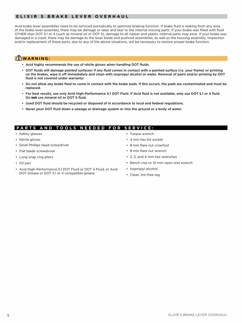
avid brake lever assemblies need to be serviced periodically to optimize braking function. if brake fluid is leaking from any area of the brake lever assembly, there may be damage or wear and tear to the internal moving parts. if your brake was filled with fluid otHER than dot 5.1 or 4 (such as mineral oil or dot 5), damage to all rubber and plastic internal parts may exist. if your brake was damaged in a crash, there may be damage to the lever blade and pushrod assemblies, as well as the housing assembly. inspection and/or replacement of these parts, due to any of the above situations, will be necessary to restore proper brake function.
Wa r n i n g :• AvidhighlyrecommendstheuseofnitrilegloveswhenhandlingDOTfluids.
• DOTfluidswilldamagepaintedsurfaces!Ifanyfluidcomesincontactwithapaintedsurface(i.e.yourframe)orprintingonthebrakes,wipeitoffimmediatelyandcleanwithisopropylalcoholorwater.Removalofpaintand/orprintingbyDOTfluidisnotcoveredunderwarranty!
• Donotallowanybrakefluidtocomeincontactwiththebrakepads.Ifthisoccurs,thepadsarecontaminatedandmustbereplaced.
• Forbestresults,useonlyAvidHigh-Performance5.1DOTFluid.IfAvidfluidisnotavailable,onlyuseDOT5.1or4fluid.DonotusemineraloilorDOT5fluid.
• UsedDOTfluidshouldberecycledordisposedofinaccordancetolocalandfederalregulations.
• NeverpourDOTfluiddownasewageordrainagesystemorintothegroundorabodyofwater.
p a r T s a n d T o o l s n e e d e d f o r s e r v i C e :• Safety glasses
• Nitrile gloves
• Small Phillips head screwdriver
• flat blade screwdriver
• long snap ring pliers
• oil pan
• avid High-Performance 5.1 dot fluid or dot 4 fluid, or avid dot Grease or dot 5.1 or 4 compatible grease
• torque wrench
• 4 mm hex bit socket
• 8 mm flare nut crowfoot
• 8 mm flare nut wrench
• 2, 3, and 4 mm hex wrenches
• Bench vise or 10 mm open end wrench
• isopropyl alcohol
• Clean, lint-free rag
6 elixir 5 brake lever overhaul
A
h
c
G
d
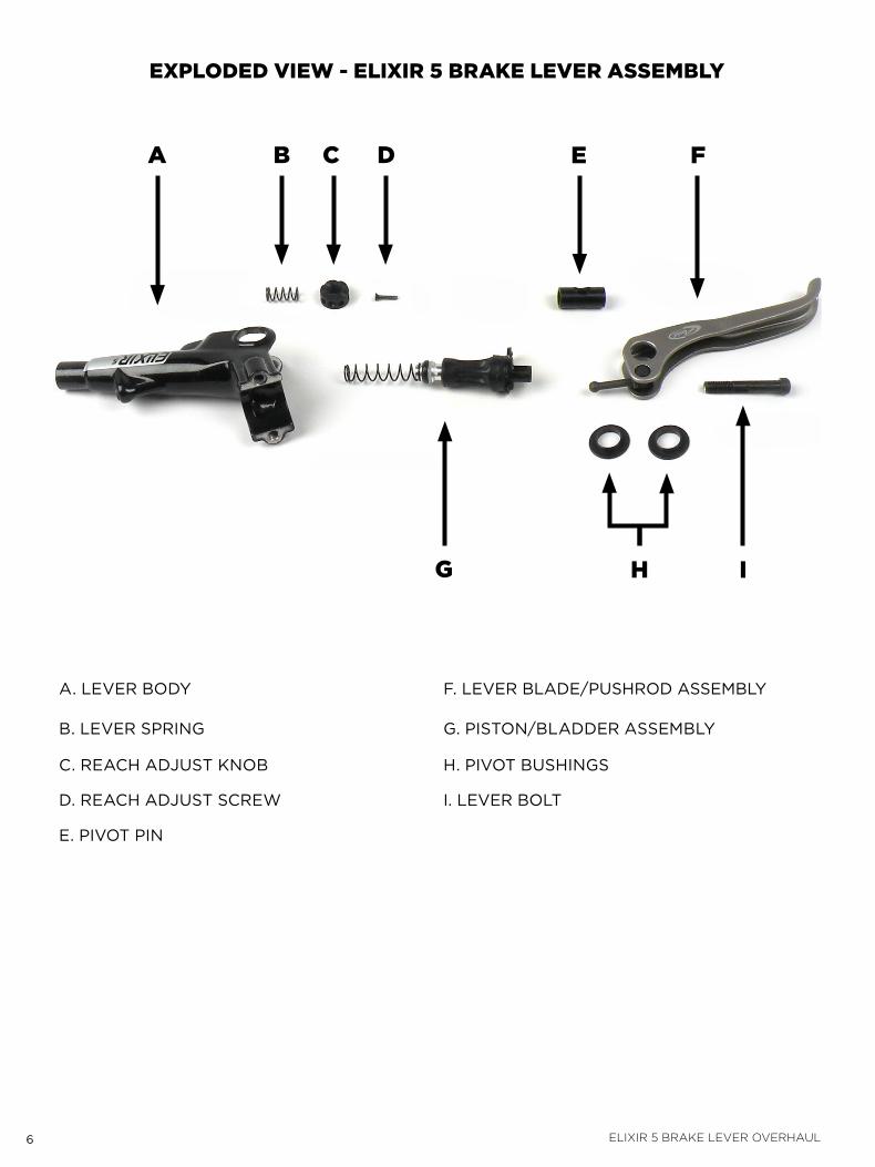
ExplodEd vIEw - ElIxIR 5 bRAkE lEvER ASSEmblY
E
a. lEvER BodY f. lEvER BladE/PUSHRod aSSEMBlY
B. lEvER SPRiNG G. PiStoN/BladdER aSSEMBlY
C. REaCH adjUSt kNoB H. Pivot BUSHiNGS
d. REaCH adjUSt SCREW i. lEvER Bolt
E. Pivot PiN
I
b F
7 elixir 5 brake lever overhaul
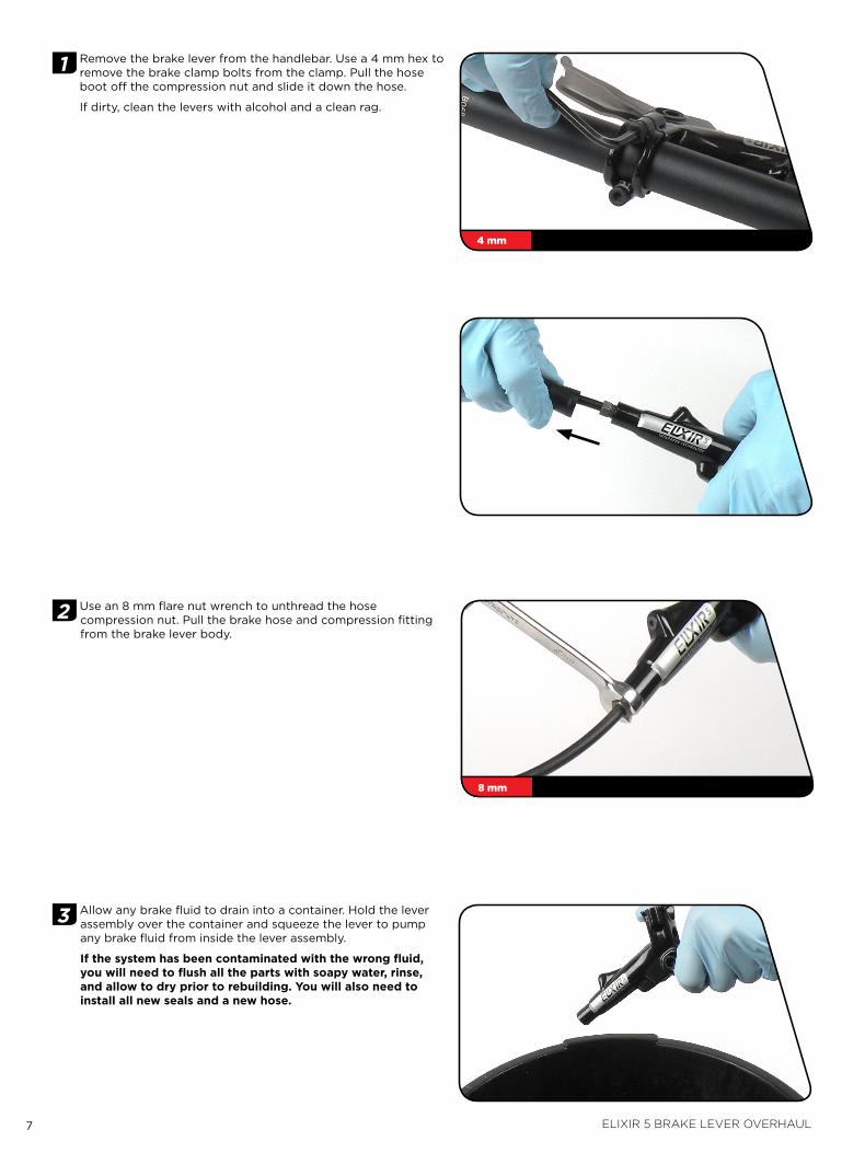
1 Remove the brake lever from the handlebar. Use a 4 mm hex to remove the brake clamp bolts from the clamp. Pull the hose boot off the compression nut and slide it down the hose.
if dirty, clean the levers with alcohol and a clean rag.
2 Use an 8 mm flare nut wrench to unthread the hose compression nut. Pull the brake hose and compression fitting from the brake lever body.
3 allow any brake fluid to drain into a container. Hold the lever assembly over the container and squeeze the lever to pump any brake fluid from inside the lever assembly.
if the system has been contaminated with the wrong fluid, you will need to flush all the parts with soapy water, rinse, and allow to dry prior to rebuilding. You will also need to install all new seals and a new hose.
4 mm
8 mm
8 elixir 5 brake lever overhaul
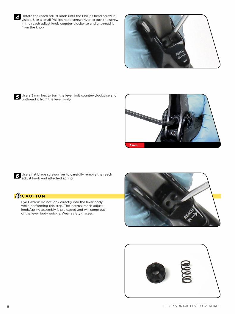
4 Rotate the reach adjust knob until the Phillips head screw is visible. Use a small Phillips head screwdriver to turn the screw in the reach adjust knob counter-clockwise and unthread it from the knob.
5 Use a 3 mm hex to turn the lever bolt counter-clockwise and unthread it from the lever body.
6 Use a flat blade screwdriver to carefully remove the reach adjust knob and attached spring.
C au Ti o nEye Hazard: do not look directly into the lever body while performing this step. the internal reach adjust knob/spring assembly is preloaded and will come out of the lever body quickly. Wear safety glasses.
3 mm
9 elixir 5 brake lever overhaul
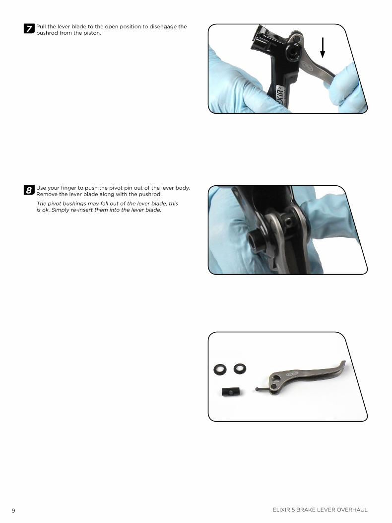
7 Pull the lever blade to the open position to disengage the pushrod from the piston.
8 Use your finger to push the pivot pin out of the lever body. Remove the lever blade along with the pushrod.
the pivot bushings may fall out of the lever blade, this is ok. Simply re-insert them into the lever blade.
10 elixir 5 brake lever overhaul
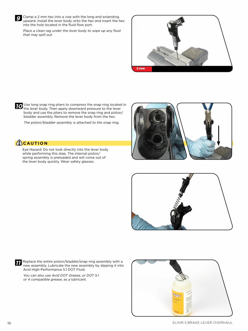
9 Clamp a 2 mm hex into a vise with the long end extending upward. install the lever body onto the hex and insert the hex into the hole located in the fluid flow port.
Place a clean rag under the lever body to wipe up any fluid that may spill out.
10 Use long snap ring pliers to compress the snap ring located in the lever body. then apply downward pressure to the lever body and use the pliers to remove the snap ring and piston/bladder assembly. Remove the lever body from the hex.
the piston/bladder assembly is attached to the snap ring.
C au Ti o nEye Hazard: do not look directly into the lever body while performing this step. the internal piston/spring assembly is preloaded and will come out of the lever body quickly. Wear safety glasses.
11 Replace the entire piston/bladder/snap ring assembly with a new assembly. lubricate the new assembly by dipping it into avid High-Performance 5.1 dot fluid.
You can also use avid dot Grease, or dot 5.1 or 4 compatible grease, as a lubricant.
2 mm
11 elixir 5 brake lever overhaul
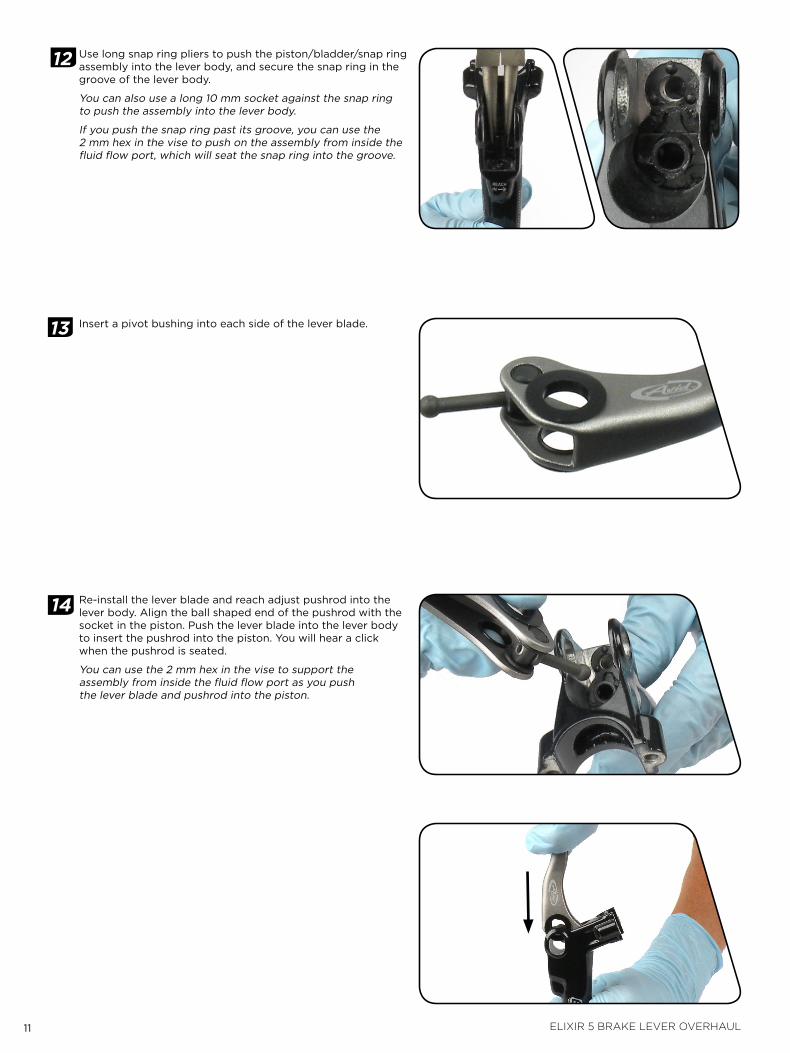
12 Use long snap ring pliers to push the piston/bladder/snap ring assembly into the lever body, and secure the snap ring in the groove of the lever body.
You can also use a long 10 mm socket against the snap ring to push the assembly into the lever body.
if you push the snap ring past its groove, you can use the 2 mm hex in the vise to push on the assembly from inside the fluid flow port, which will seat the snap ring into the groove.
13 insert a pivot bushing into each side of the lever blade.
14 Re-install the lever blade and reach adjust pushrod into the lever body. align the ball shaped end of the pushrod with the socket in the piston. Push the lever blade into the lever body to insert the pushrod into the piston. You will hear a click when the pushrod is seated.
You can use the 2 mm hex in the vise to support the assembly from inside the fluid flow port as you push the lever blade and pushrod into the piston.
12 elixir 5 brake lever overhaul
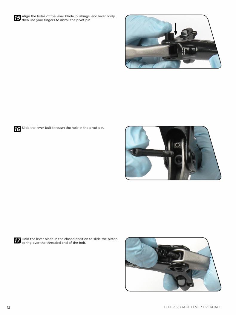
15 align the holes of the lever blade, bushings, and lever body, then use your fingers to install the pivot pin.
16 Slide the lever bolt through the hole in the pivot pin.
17 Hold the lever blade in the closed position to slide the piston spring over the threaded end of the bolt.
13 elixir 5 brake lever overhaul
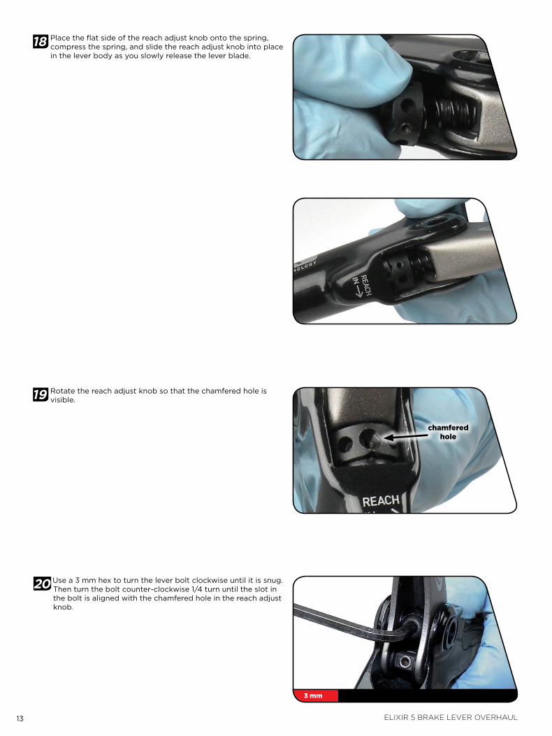
18 Place the flat side of the reach adjust knob onto the spring, compress the spring, and slide the reach adjust knob into place in the lever body as you slowly release the lever blade.
19 Rotate the reach adjust knob so that the chamfered hole is visible.
20 Use a 3 mm hex to turn the lever bolt clockwise until it is snug. then turn the bolt counter-clockwise 1/4 turn until the slot in the bolt is aligned with the chamfered hole in the reach adjust knob.
chamfered hole
3 mm
14 elixir 5 brake lever overhaul
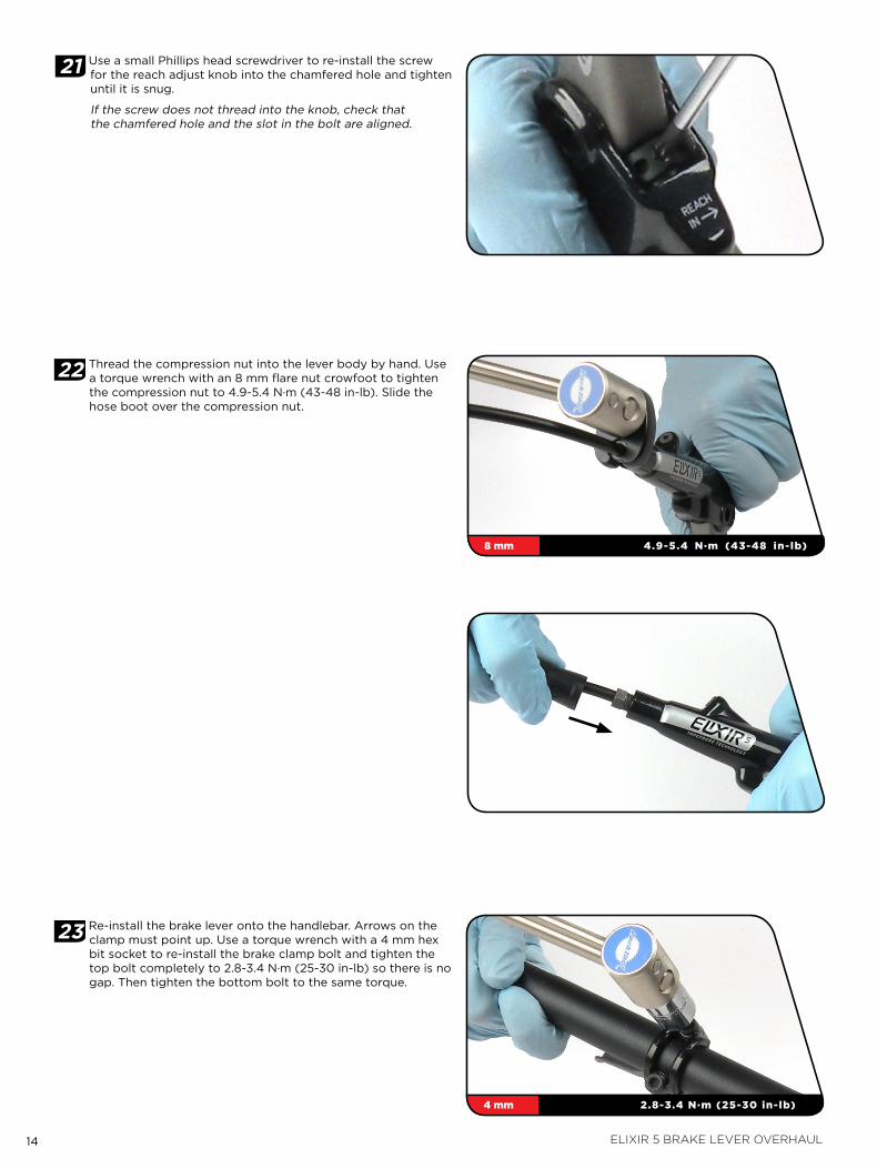
21 Use a small Phillips head screwdriver to re-install the screw for the reach adjust knob into the chamfered hole and tighten until it is snug.
if the screw does not thread into the knob, check that the chamfered hole and the slot in the bolt are aligned.
22 thread the compression nut into the lever body by hand. Use a torque wrench with an 8 mm flare nut crowfoot to tighten the compression nut to 4.9-5.4 N∙m (43-48 in-lb). Slide the hose boot over the compression nut.
23 Re-install the brake lever onto the handlebar. arrows on the clamp must point up. Use a torque wrench with a 4 mm hex bit socket to re-install the brake clamp bolt and tighten the top bolt completely to 2.8-3.4 N∙m (25-30 in-lb) so there is no gap. then tighten the bottom bolt to the same torque.
8 mm 4.9-5.4 N∙m (43-48 in-lb)
4 mm 2.8-3.4 N∙m (25-30 in-lb)
15 elixir 5 brake caliper overhaul
e l i x i r 5 b r a k e C a l i p e r o v e r h a u lavid brake lever assemblies need to be serviced periodically in order to optimize braking function. if brake fluid is leaking from any area of the brake lever assembly, there may be damage or wear and tear to the internal moving parts. if your brake was filled with fluid otHER than dot 5.1 or 4 (such as mineral oil or dot 5), damage to all rubber and plastic internal parts may exist. if your brake was damaged in a crash, there may be damage to the lever blade and pushrod assemblies, as well as the housing assembly. inspection and/or replacement of these parts, due to any of the above situations, will be necessary to restore proper brake function.
Wa r n i n g :• AvidhighlyrecommendstheuseofrubbergloveswhenhandlingDOTfluids.
• DOTfluidswilldamagepaintedsurfaces!Ifanyfluidcomesincontactwithapaintedsurface(i.e.yourframe)orprintingonthebrakes,wipeitoffimmediatelyandcleanwithisopropylalcoholorwater.Removalofpaintand/orprintingbyDOTfluidisnotcoveredunderwarranty!
• Donotallowanybrakefluidtocomeincontactwiththebrakepads.Ifthisoccurs,thepadsarecontaminatedandmustbereplaced.
• Forbestresults,useonlyAvidHigh-Performance5.1DOTFluid.IfAvidfluidisnotavailable,onlyuseDOT5.1or4fluid.DonotusemineraloilorDOT5fluid.
• UsedDOTfluidshouldberecycledordisposedofinaccordancetolocalandfederalregulations.
• NeverpourDOTfluiddownasewageordrainagesystemorintothegroundorabodyofwater.
p a r T s a n d T o o l s n e e d e d f o r s e r v i C e :• Safety glasses
• Nitrile gloves
• avid High-Performance 5.1 dot fluid or dot 4 fluid, or avid dot Grease or dot 5.1 or 4 compatible grease
• oil pan
• flat blade screwdriver
• air compressor with blow gun chuck
• torque wrench
• 5 mm hex bit socket
• 8 mm flare nut crowfoot
• 8 mm open end wrench
• 2.5 mm and 5 mm hex wrenches
• Sharp pick
• Clean, lint-free rags
• isopropyl alcohol
T r o u b l e s h o o T i n g‘Sticky’ or slow brake pad return feel
Before completely disassembling your caliper, it’s worth trying to loosen the sticky piston. try the following:
1. Clamp the bicycle in a bicycle work stand.
2. Spin the affected wheel. lightly squeeze the brake lever and watch the brake pads when the lever is released.
3. determine which side of the caliper has a slow returning brake piston.
4. Remove the caliper from the bicycle. if you have a caliper mounting bracket, remove the bracket with the caliper attached.
5. Remove e-clip from the guide pin groove on top of the caliper. Use a 2.5 mm hex to remove the guide pin from the caliper.
6. Remove both brake pads and h-spring.
7. Use a 10 mm box wrench to press the working piston into caliper body.
8. While continuing to hold the piston inside the caliper body, squeeze the brake lever slowly to move the sticky piston inward. Press the piston back into the caliper again.
9. Repeat these steps to correct caliper piston inner o-ring position.
10. Both pistons should now be moving freely. Re-install the spring pad clip, h-spring, and pads into the caliper. if there is no improvement, continue with caliper service.
11. Re-install the caliper (or mounting bracket with attached caliper) on the bicycle. You may need to re-center the caliper to the rotor. if you removed the caliper without an adapter, or removed it from the adapter, it will need to be re-centered. Spin the wheel and check brake function.
16 elixir 5 brake caliper overhaul
1 Use a 5 mm hex to remove the brake caliper from the fork or frame and remove the caliper mounting bracket and hardware from the caliper. Set aside in the correct order (not pictured).
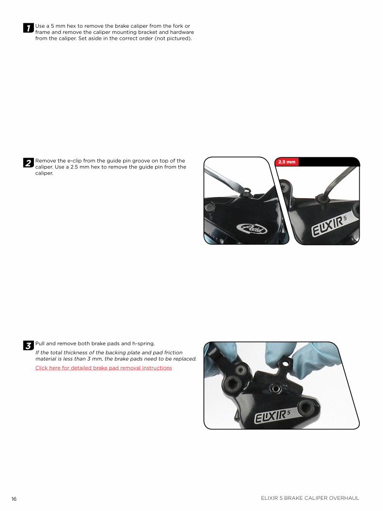
2 Remove the e-clip from the guide pin groove on top of the caliper. Use a 2.5 mm hex to remove the guide pin from the caliper.
3 Pull and remove both brake pads and h-spring.
if the total thickness of the backing plate and pad friction material is less than 3 mm, the brake pads need to be replaced.
Click here for detailed brake pad removal instructions
2.5 mm
17 elixir 5 brake caliper overhaul
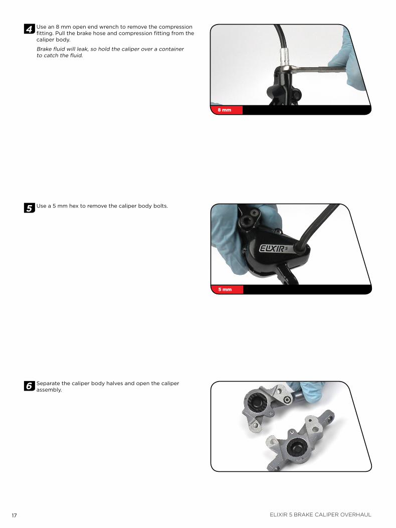
4 Use an 8 mm open end wrench to remove the compression fitting. Pull the brake hose and compression fitting from the caliper body.
Brake fluid will leak, so hold the caliper over a container to catch the fluid.
5 Use a 5 mm hex to remove the caliper body bolts.
6 Separate the caliper body halves and open the caliper assembly.
8 mm
5 mm
18 elixir 5 brake caliper overhaul
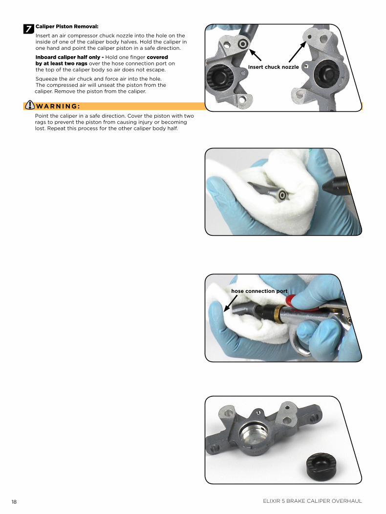
7 caliper piston Removal:
insert an air compressor chuck nozzle into the hole on the inside of one of the caliper body halves. Hold the caliper in one hand and point the caliper piston in a safe direction.
Inboard caliper half only - Hold one finger covered by at least two rags over the hose connection port on the top of the caliper body so air does not escape.
Squeeze the air chuck and force air into the hole. the compressed air will unseat the piston from the caliper. Remove the piston from the caliper.
Wa r n i n g :Point the caliper in a safe direction. Cover the piston with two rags to prevent the piston from causing injury or becoming lost. Repeat this process for the other caliper body half.
insert chuck nozzle
hose connection port
19 elixir 5 brake caliper overhaul
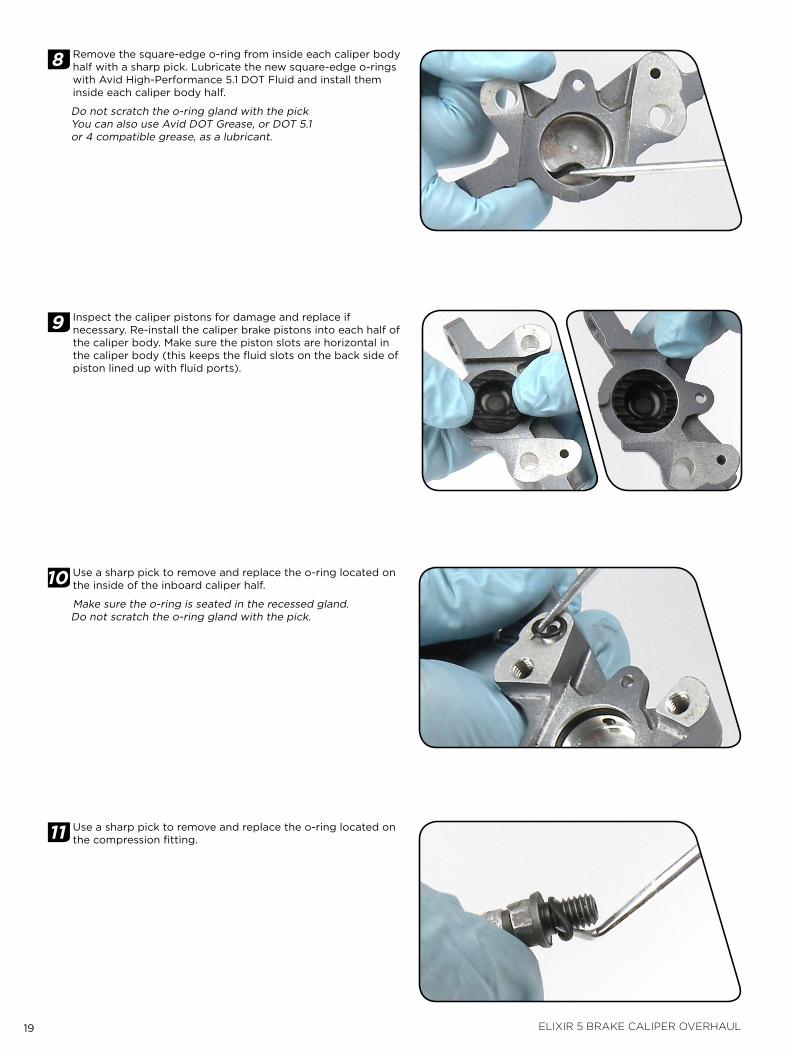
8 Remove the square-edge o-ring from inside each caliper body half with a sharp pick. lubricate the new square-edge o-rings with avid High-Performance 5.1 dot fluid and install them inside each caliper body half.
do not scratch the o-ring gland with the pick You can also use avid dot Grease, or dot 5.1 or 4 compatible grease, as a lubricant.
9 inspect the caliper pistons for damage and replace if necessary. Re-install the caliper brake pistons into each half of the caliper body. Make sure the piston slots are horizontal in the caliper body (this keeps the fluid slots on the back side of piston lined up with fluid ports).
10 Use a sharp pick to remove and replace the o-ring located on the inside of the inboard caliper half.
Make sure the o-ring is seated in the recessed gland. do not scratch the o-ring gland with the pick.
11 Use a sharp pick to remove and replace the o-ring located on the compression fitting.
20 elixir 5 brake caliper overhaul
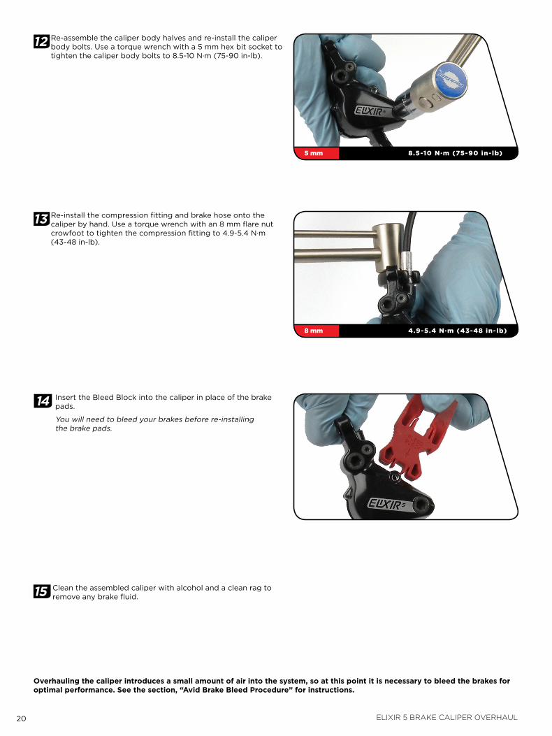
12 Re-assemble the caliper body halves and re-install the caliper body bolts. Use a torque wrench with a 5 mm hex bit socket to tighten the caliper body bolts to 8.5-10 N∙m (75-90 in-lb).
13 Re-install the compression fitting and brake hose onto the caliper by hand. Use a torque wrench with an 8 mm flare nut crowfoot to tighten the compression fitting to 4.9-5.4 N∙m (43-48 in-lb).
14 insert the Bleed Block into the caliper in place of the brake pads.
You will need to bleed your brakes before re-installing the brake pads.
15 Clean the assembled caliper with alcohol and a clean rag to remove any brake fluid.
overhauling the caliper introduces a small amount of air into the system, so at this point it is necessary to bleed the brakes for optimal performance. see the section, “avid brake bleed procedure” for instructions.
5 mm 8.5-10 N∙m (75-90 in-lb)
8 mm 4.9-5.4 N∙m (43-48 in-lb)
21 avid brake hose length adjustment
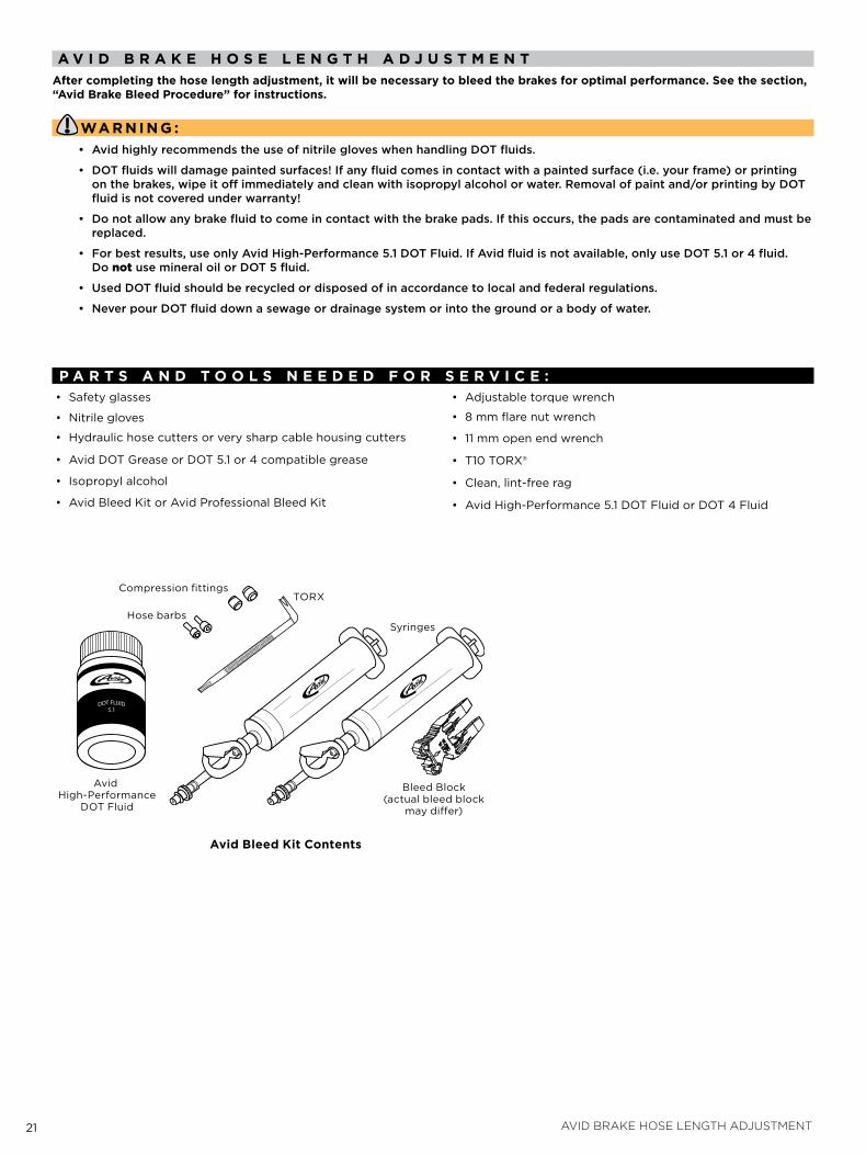
a v i d b r a k e h o s e l e n g T h a d j u s T m e n Tafter completing the hose length adjustment, it will be necessary to bleed the brakes for optimal performance. see the section, “avid brake bleed procedure” for instructions.
Wa r n i n g :• AvidhighlyrecommendstheuseofnitrilegloveswhenhandlingDOTfluids.
• DOTfluidswilldamagepaintedsurfaces!Ifanyfluidcomesincontactwithapaintedsurface(i.e.yourframe)orprintingonthebrakes,wipeitoffimmediatelyandcleanwithisopropylalcoholorwater.Removalofpaintand/orprintingbyDOTfluidisnotcoveredunderwarranty!
• Donotallowanybrakefluidtocomeincontactwiththebrakepads.Ifthisoccurs,thepadsarecontaminatedandmustbereplaced.
• Forbestresults,useonlyAvidHigh-Performance5.1DOTFluid.IfAvidfluidisnotavailable,onlyuseDOT5.1or4fluid.DonotusemineraloilorDOT5fluid.
• UsedDOTfluidshouldberecycledordisposedofinaccordancetolocalandfederalregulations.
• NeverpourDOTfluiddownasewageordrainagesystemorintothegroundorabodyofwater.
p a r T s a n d T o o l s n e e d e d f o r s e r v i C e :• Safety glasses
• Nitrile gloves
• Hydraulic hose cutters or very sharp cable housing cutters
• avid dot Grease or dot 5.1 or 4 compatible grease
• isopropyl alcohol
• avid Bleed kit or avid Professional Bleed kit
• adjustable torque wrench
• 8 mm flare nut wrench
• 11 mm open end wrench
• t10 toRX®
• Clean, lint-free rag
• avid High-Performance 5.1 dot fluid or dot 4 fluid
avid bleed kit Contents
avid High-Performance
dot fluid
toRX
Hose barbs
Compression fittings
Syringes
Bleed Block(actual bleed block
may differ)
22 avid brake hose length adjustment
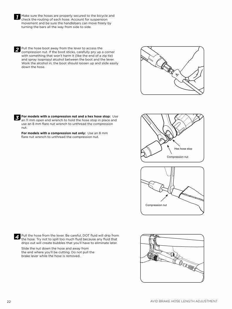
1 Make sure the hoses are properly secured to the bicycle and check the routing of each hose. account for suspension movement and be sure the handlebars can move freely by turning the bars all the way from side to side.
2 Pull the hose boot away from the lever to access the compression nut. if the boot sticks, carefully pry up a corner with something that won’t harm it (like the end of a zip tie) and spray isopropyl alcohol between the boot and the lever. Work the alcohol in; the boot should loosen up and slide easily down the hose.
3 for models with a compression nut and a hex hose stop: Use an 11 mm open end wrench to hold the hose stop in place and use an 8 mm flare nut wrench to unthread the compression nut.
for models with a compression nut only: Use an 8 mm flare nut wrench to unthread the compression nut.
4 Pull the hose from the lever. Be careful, dot fluid will drip from the hose. try not to spill too much fluid because any fluid that drips out will create bubbles that you’ll have to eliminate later.
Slide the nut down the hose and away from the end where you’ll be cutting. do not pull the brake lever while the hose is removed.
Hex hose stop
Compression nut
Compression nut
23 avid brake hose length adjustment
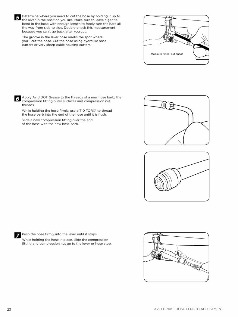
5 determine where you need to cut the hose by holding it up to the lever in the position you like. Make sure to leave a gentle bend in the hose with enough length to freely turn the bars all the way from side to side. double-check this measurement because you can’t go back after you cut.
the groove in the lever nose marks the spot where you’ll cut the hose. Cut the hose using hydraulic hose cutters or very sharp cable housing cutters.
6 apply avid dot Grease to the threads of a new hose barb, the compression fitting outer surfaces and compression nut threads.
While holding the hose firmly, use a t10 toRX® to thread the hose barb into the end of the hose until it is flush.
Slide a new compression fitting over the end of the hose with the new hose barb.
7 Push the hose firmly into the lever until it stops.
While holding the hose in place, slide the compression fitting and compression nut up to the lever or hose stop.
Measure twice, cut once!
24 avid brake hose length adjustment
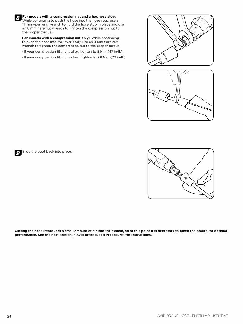
8 for models with a compression nut and a hex hose stop: While continuing to push the hose into the hose stop, use an 11 mm open end wrench to hold the hose stop in place and use an 8 mm flare nut wrench to tighten the compression nut to the proper torque.
for models with a compression nut only: While continuing to push the hose into the lever body, use an 8 mm flare nut wrench to tighten the compression nut to the proper torque.
∙ if your compression fitting is alloy, tighten to 5 N∙m (47 in-lb).
∙ if your compression fitting is steel, tighten to 7.8 N∙m (70 in-lb)
9 Slide the boot back into place.
Cutting the hose introduces a small amount of air into the system, so at this point it is necessary to bleed the brakes for optimal performance. see the next section, “ avid brake bleed procedure” for instructions.
25 avid brake bleed procedure
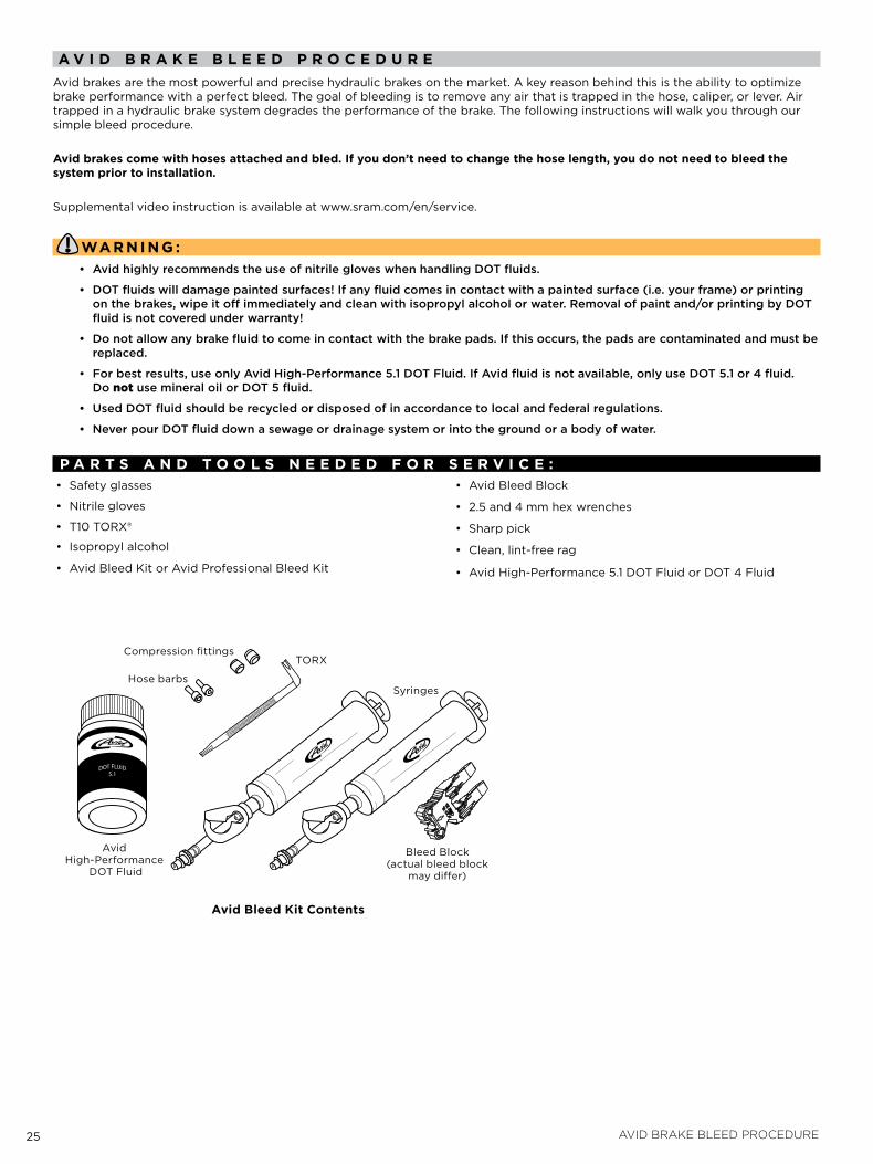
a v i d b r a k e b l e e d p r o C e d u r eavid brakes are the most powerful and precise hydraulic brakes on the market. a key reason behind this is the ability to optimize brake performance with a perfect bleed. the goal of bleeding is to remove any air that is trapped in the hose, caliper, or lever. air trapped in a hydraulic brake system degrades the performance of the brake. the following instructions will walk you through our simple bleed procedure.
avid brakes come with hoses attached and bled. if you don’t need to change the hose length, you do not need to bleed the system prior to installation.
Supplemental video instruction is available at www.sram.com/en/service.
Wa r n i n g :• AvidhighlyrecommendstheuseofnitrilegloveswhenhandlingDOTfluids.
• DOTfluidswilldamagepaintedsurfaces!Ifanyfluidcomesincontactwithapaintedsurface(i.e.yourframe)orprintingonthebrakes,wipeitoffimmediatelyandcleanwithisopropylalcoholorwater.Removalofpaintand/orprintingbyDOTfluidisnotcoveredunderwarranty!
• Donotallowanybrakefluidtocomeincontactwiththebrakepads.Ifthisoccurs,thepadsarecontaminatedandmustbereplaced.
• Forbestresults,useonlyAvidHigh-Performance5.1DOTFluid.IfAvidfluidisnotavailable,onlyuseDOT5.1or4fluid.DonotusemineraloilorDOT5fluid.
• UsedDOTfluidshouldberecycledordisposedofinaccordancetolocalandfederalregulations.
• NeverpourDOTfluiddownasewageordrainagesystemorintothegroundorabodyofwater.
p a r T s a n d T o o l s n e e d e d f o r s e r v i C e :• Safety glasses
• Nitrile gloves
• t10 toRX®
• isopropyl alcohol
• avid Bleed kit or avid Professional Bleed kit
• avid Bleed Block
• 2.5 and 4 mm hex wrenches
• Sharp pick
• Clean, lint-free rag
• avid High-Performance 5.1 dot fluid or dot 4 fluid
avid bleed kit Contents
avid High-Performance
dot fluid
toRX
Hose barbs
Compression fittings
Syringes
Bleed Block(actual bleed block
may differ)
26 avid brake bleed procedure
When bleeding avid brakes, keep in mind that you are simply forcing air bubbles out of the system. We recommend that you bleed your brakes at least once a year to ensure optimal performance. if you ride frequently or in aggressive terrain, you should bleed your brakes more often.
When bleeding brakes, you may notice discoloration of the old fluid as it exits the system into the syringe at the lever. if the fluid is severely discolored, this indicates that the fluid is very old. in this case, bleeding the system twice in order to completely remove the old fluid is recommended.
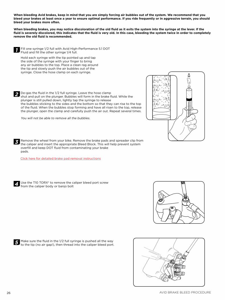
1 fill one syringe 1/2 full with avid High-Performance 5.1 dot fluid and fill the other syringe 1/4 full.
Hold each syringe with the tip pointed up and tap the side of the syringe with your finger to bring any air bubbles to the top. Place a clean rag around the tip and slowly push the air bubbles out of the syringe. Close the hose clamp on each syringe.
2 de-gas the fluid in the 1/2 full syringe. leave the hose clamp shut and pull on the plunger. Bubbles will form in the brake fluid. While the plunger is still pulled down, lightly tap the syringe to release the bubbles sticking to the sides and the bottom so that they can rise to the top of the fluid. When the bubbles stop forming and have all risen to the top, release the plunger, open the clamp and carefully push the air out. Repeat several times.
You will not be able to remove all the bubbles.
3 Remove the wheel from your bike. Remove the brake pads and spreader clip from the caliper and insert the appropriate Bleed Block. this will help prevent system overfill and keep dot fluid from contaminating your brake pads.
Click here for detailed brake pad removal instructions
4 Use the t10 toRX® to remove the caliper bleed port screw from the caliper body or banjo bolt
5 Make sure the fluid in the 1/2 full syringe is pushed all the way to the tip (no air gap!), then thread into the caliper bleed port.
27 avid brake bleed procedure
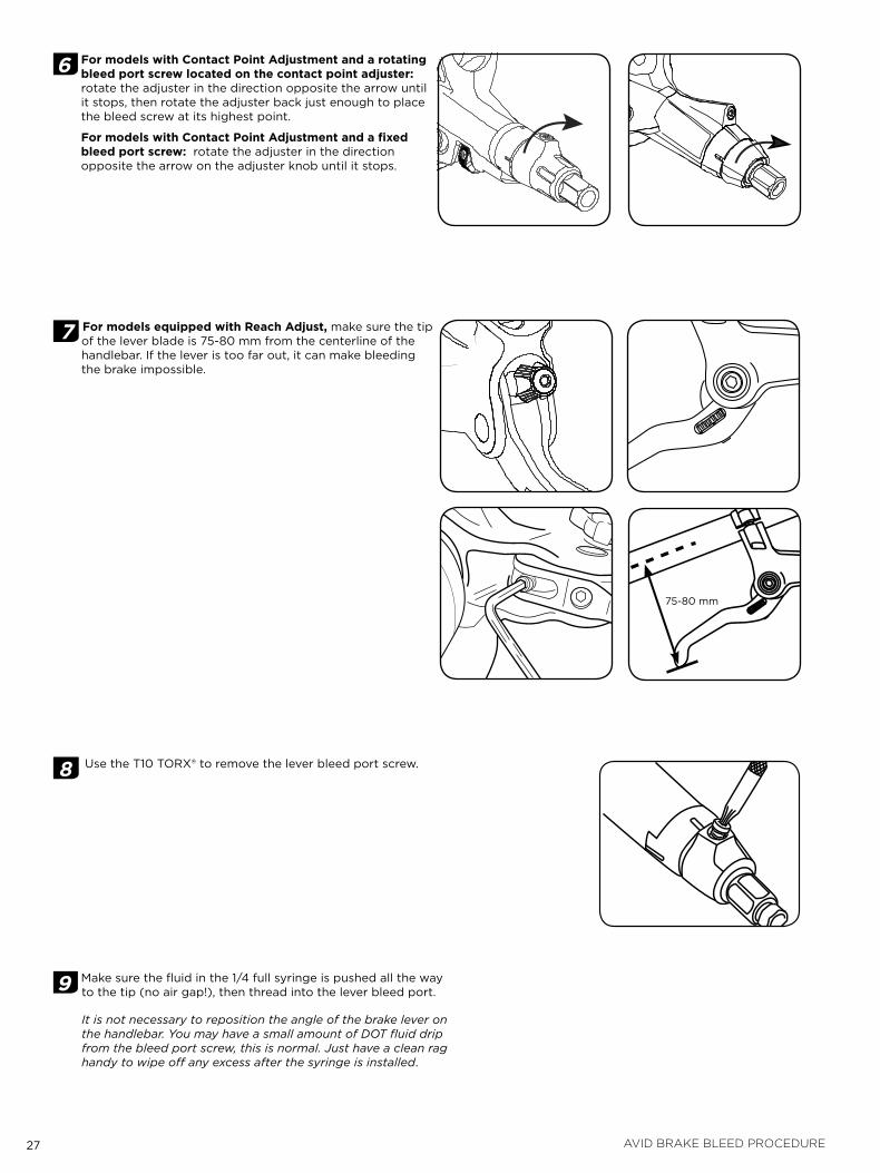
6 for models with Contact point adjustment and a rotating bleed port screw located on the contact point adjuster: rotate the adjuster in the direction opposite the arrow until it stops, then rotate the adjuster back just enough to place the bleed screw at its highest point.
for models with Contact point adjustment and a fixed bleed port screw: rotate the adjuster in the direction opposite the arrow on the adjuster knob until it stops.
7 for models equipped with reach adjust, make sure the tip of the lever blade is 75-80 mm from the centerline of the handlebar. if the lever is too far out, it can make bleeding the brake impossible.
8 Use the t10 toRX® to remove the lever bleed port screw.
9 Make sure the fluid in the 1/4 full syringe is pushed all the way to the tip (no air gap!), then thread into the lever bleed port.
It is not necessary to reposition the angle of the brake lever on the handlebar. You may have a small amount of DOT fluid drip from the bleed port screw, this is normal. Just have a clean rag handy to wipe off any excess after the syringe is installed.
75-80 mm
28 avid brake bleed procedure
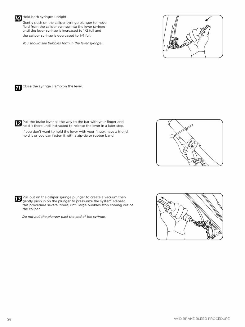
10 Hold both syringes upright.
Gently push on the caliper syringe plunger to move fluid from the caliper syringe into the lever syringe until the lever syringe is increased to 1/2 full and the caliper syringe is decreased to 1/4 full.
You should see bubbles form in the lever syringe.
11 Close the syringe clamp on the lever.
12 Pull the brake lever all the way to the bar with your finger and hold it there until instructed to release the lever in a later step.
if you don’t want to hold the lever with your finger, have a friend hold it or you can fasten it with a zip-tie or rubber band.
13 Pull out on the caliper syringe plunger to create a vacuum then gently push in on the plunger to pressurize the system. Repeat this procedure several times, until large bubbles stop coming out of the caliper.
Do not pull the plunger past the end of the syringe.
29 avid brake bleed procedure
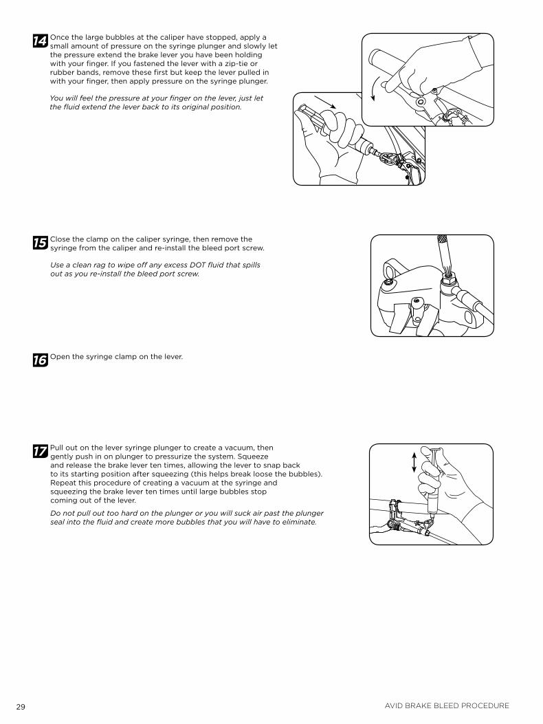
14 once the large bubbles at the caliper have stopped, apply a small amount of pressure on the syringe plunger and slowly let the pressure extend the brake lever you have been holding with your finger. if you fastened the lever with a zip-tie or rubber bands, remove these first but keep the lever pulled in with your finger, then apply pressure on the syringe plunger.
You will feel the pressure at your finger on the lever, just let the fluid extend the lever back to its original position.
15 Close the clamp on the caliper syringe, then remove the syringe from the caliper and re-install the bleed port screw.
Use a clean rag to wipe off any excess DOT fluid that spills out as you re-install the bleed port screw.
16 open the syringe clamp on the lever.
17 Pull out on the lever syringe plunger to create a vacuum, then gently push in on plunger to pressurize the system. Squeeze and release the brake lever ten times, allowing the lever to snap back to its starting position after squeezing (this helps break loose the bubbles). Repeat this procedure of creating a vacuum at the syringe and squeezing the brake lever ten times until large bubbles stop coming out of the lever.
Do not pull out too hard on the plunger or you will suck air past the plunger seal into the fluid and create more bubbles that you will have to eliminate.
30 avid brake bleed procedure
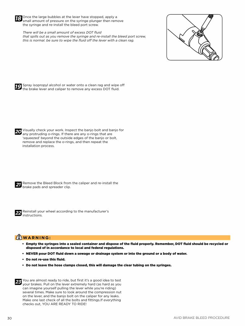
18 once the large bubbles at the lever have stopped, apply a small amount of pressure on the syringe plunger then remove the syringe and re-install the bleed port screw.
There will be a small amount of excess DOT fluid that spills out as you remove the syringe and re-install the bleed port screw, this is normal. be sure to wipe the fluid off the lever with a clean rag.
19 Spray isopropyl alcohol or water onto a clean rag and wipe off the brake lever and caliper to remove any excess dot fluid.
20 visually check your work. inspect the banjo bolt and banjo for any protruding o-rings. if there are any o-rings that are ‘squeezed’ beyond the outside edges of the banjo or bolt, remove and replace the o-rings, and then repeat the installation process.
21 Remove the Bleed Block from the caliper and re-install the brake pads and spreader clip.
22 Reinstall your wheel according to the manufacturer’s instructions.
Wa r n i n g :• Empty the syringes into a sealed container and dispose of the fluid properly. Remember, doT fluid should be recycled or
disposed of in accordance to local and federal regulations.
• NEvER pour doT fluid down a sewage or drainage system or into the ground or a body of water.
• do not re-use this fluid.
• do not leave the hose clamps closed, this will damage the clear tubing on the syringes.
23 You are almost ready to ride, but first it’s a good idea to test your brakes. Pull on the lever extremely hard (as hard as you can imagine yourself pulling the lever while you’re riding) several times. Make sure to look around the compression nut on the lever, and the banjo bolt on the caliper for any leaks. Make one last check of all the bolts and fittings.if everything checks out, YoU aRE REadY to RidE!
31 disc brake pad installation instructions
d i s C b r a k e p a d i n s T a l l a T i o n i n s T r u C T i o n s
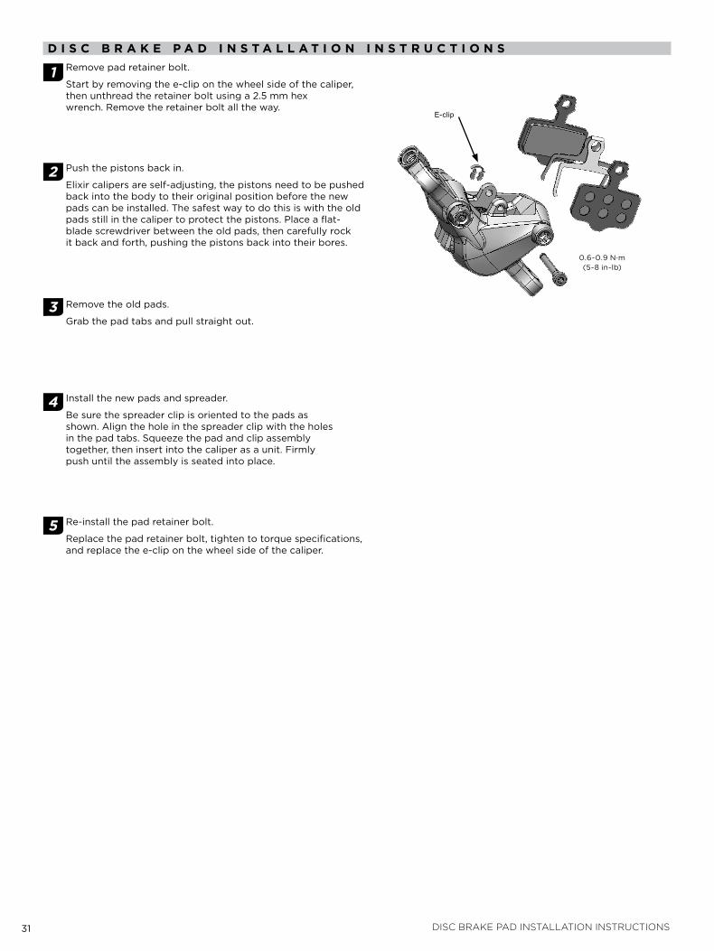
1 Remove pad retainer bolt.
Start by removing the e-clip on the wheel side of the caliper, then unthread the retainer bolt using a 2.5 mm hex wrench. Remove the retainer bolt all the way.
2 Push the pistons back in.
Elixir calipers are self-adjusting, the pistons need to be pushed back into the body to their original position before the new pads can be installed. the safest way to do this is with the old pads still in the caliper to protect the pistons. Place a flat-blade screwdriver between the old pads, then carefully rock it back and forth, pushing the pistons back into their bores.
3 Remove the old pads.
Grab the pad tabs and pull straight out.
4 install the new pads and spreader.
Be sure the spreader clip is oriented to the pads as shown. align the hole in the spreader clip with the holes in the pad tabs. Squeeze the pad and clip assembly together, then insert into the caliper as a unit. firmly push until the assembly is seated into place.
5 Re-install the pad retainer bolt.
Replace the pad retainer bolt, tighten to torque specifications, and replace the e-clip on the wheel side of the caliper.
0.6-0.9 N∙m (5-8 in-lb)
E-clip
32 disc brake pad and rotor bed-in procedure
d i s C b r a k e p a d a n d r o T o r b e d - i n p r o C e d u r eall new brake pads and rotors should be put through a wear-in process called ‘bed-in’. the bed-in procedure, which should be performed prior to your first ride, ensures the most consistent and powerful braking feel along with the quietest braking in most riding conditions. the bed-in process heats up the brake pads and rotors which deposits an even layer of brake pad material (transfer layer) to the braking surface of the rotor. it this transfer layer that optimizes braking performance.
Wa r n i n g :The bed-in process requires you to perform heavy braking. You must be familiar with the power and operation of disc brakes. braking heavily when not familiar with the power and operation of disc brakes could cause you to lose control of your bicycle, which could lead to a crash and could lead to serious injury and/or death. if you are unfamiliar with the power and operation of disc brakes, you should have the bed-in process performed by a qualified bicycle mechanic.
i m p o r Ta n T:to safely achieve optimal results, remain seated on the bike during the entire bed-in procedure.
1 accelerate the bike to a moderate speed, then firmly apply the brakes until you are at walking speed. Repeat approximately twenty times.
2 accelerate the bike to a faster speed. then very firmly apply the brakes until you are at walking speed. Repeat approximately ten times.
i m p o r Ta n T:do not lock up the wheels at any point during the bed-in procedure.
3 allow the brakes to cool prior to any additional riding.

www.sram.com


