Shared interest in a more productive tomorrow. eLoran System Definition and Signal Specification Tutorial Presented by: A. Helwig, G. Offermans, C. Stout, C. Schue (UrsaNav) International Loran Association (ILA-40) – November 2011
Transcript
Shared interest in a more productive tomorrow.
eLoran System Definition and Signal Specification Tutorial
Presented by:
A. Helwig, G. Offermans, C. Stout, C. Schue (UrsaNav)
International Loran Association (ILA-40) – November 2011
EMEA Operations Bertem, Belgium
Corporate Headquarters Chesapeake, Virginia
Washington DC Metropolitan Area Leesburg, Virginia 2
Overview
• eLoran basics • eLoran System requirements
– Maritime, Aviation, Land-mobile, Timing • eLoran System Overview
– Core eLoran service provider – Application service provider
• eLoran Signal in Space – Loran pulse shape – Timing control – Loran Data Channel (LDC)
• eLoran vs. Loran-C • Maritime Harbor Entrance and Approach
EMEA Operations Bertem, Belgium
Corporate Headquarters Chesapeake, Virginia
Washington DC Metropolitan Area Leesburg, Virginia 3
eLoran Basics
• Enhanced Loran is an internationally-standardized positioning, navigation, and timing (PNT) service for use by many modes of transport and in other applications. It is the latest in the longstanding and proven series of low-frequency, LOng-RAnge Navigation (LORAN) systems, one that takes full advantage of 21st century technology.
• eLoran meets the accuracy, availability, integrity, and continuity performance requirements for aviation non-precision instrument approaches, maritime harbor entrance and approach maneuvers, land-mobile vehicle navigation, and location-based services, and is a precise source of time and frequency for applications such as telecommunications.
• eLoran is an independent, dissimilar, complement to Global Navigation Satellite Systems (GNSS). It allows GNSS users to retain the safety, security, and economic benefits of GNSS, even when their satellite services are disrupted.
From eLoran Definition Document International Loran Association November 2006
EMEA Operations Bertem, Belgium
Corporate Headquarters Chesapeake, Virginia
Washington DC Metropolitan Area Leesburg, Virginia 4
eLoran Basics (cont.)
• The core eLoran system comprises modernized control centers, transmitting stations and monitoring sites. eLoran transmissions are synchronized to an identifiable, publicly-certified, source of Coordinated Universal Time (UTC) by a method wholly independent of GNSS. This allows the eLoran Service Provider to operate on a time scale that is synchronized with but operates independently of GNSS time scales. Synchronizing to a common time source will also allow receivers to employ a mixture of eLoran and satellite signals.
• The principal difference between eLoran and traditional Loran-C is the addition of a data channel on the transmitted signal. This conveys application-specific corrections, warnings, and signal integrity information to the user’s receiver. It is this data channel that allows eLoran to meet the very demanding requirements of landing aircraft using non-precision instrument approaches and bringing ships safely into harbor in low-visibility conditions. eLoran is also capable of providing the exceedingly precise time and frequency references needed by the telecommunications systems that carry voice and internet communications.
From eLoran Definition Document International Loran Association November 2006
EMEA Operations Bertem, Belgium
Corporate Headquarters Chesapeake, Virginia
Washington DC Metropolitan Area Leesburg, Virginia 5
eLoran Development
• eLoran technology is built upon the foundation of Loran-C • eLoran has been developed over the past decade as a
response to the recognized vulnerability of GNSS, by international government agencies, industry and academia
• eLoran transmitter and receiving equipment makes full use of 21st century technology
• eLoran is recognized and recommended by the International Association of Lighthouse Authorities (IALA)
• eLoran receiver Minimum Performance Standards are being developed by the Radio Technical Commission of Maritime services (RTCM) Special Committee 127
EMEA Operations Bertem, Belgium
Corporate Headquarters Chesapeake, Virginia
Washington DC Metropolitan Area Leesburg, Virginia 6
The Difference Between eLoran and Loran-C
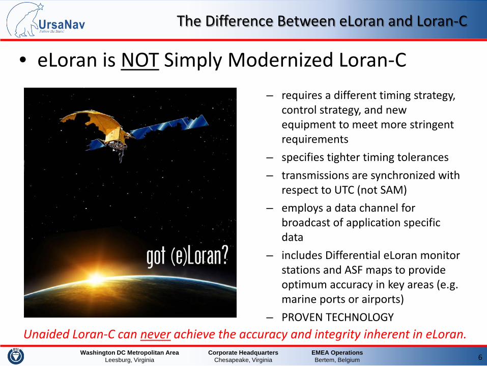
• eLoran is NOT Simply Modernized Loran-C – requires a different timing strategy,
control strategy, and new equipment to meet more stringent requirements
– specifies tighter timing tolerances – transmissions are synchronized with
respect to UTC (not SAM) – employs a data channel for
broadcast of application specific data
– includes Differential eLoran monitor stations and ASF maps to provide optimum accuracy in key areas (e.g. marine ports or airports)
– PROVEN TECHNOLOGY Unaided Loran-C can never achieve the accuracy and integrity inherent in eLoran.
EMEA Operations Bertem, Belgium
Corporate Headquarters Chesapeake, Virginia
Washington DC Metropolitan Area Leesburg, Virginia 7
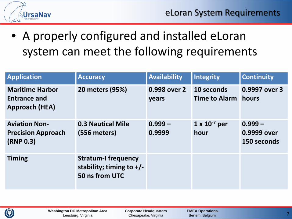
eLoran System Requirements
• A properly configured and installed eLoran system can meet the following requirements
Timing Stratum-I frequency stability; timing to +/- 50 ns from UTC
EMEA Operations Bertem, Belgium
Corporate Headquarters Chesapeake, Virginia
Washington DC Metropolitan Area Leesburg, Virginia 8
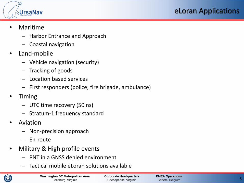
eLoran Applications
• Maritime – Harbor Entrance and Approach – Coastal navigation
• Land-mobile – Vehicle navigation (security) – Tracking of goods – Location based services – First responders (police, fire brigade, ambulance)
• Timing – UTC time recovery (50 ns) – Stratum-1 frequency standard
• Aviation – Non-precision approach – En-route
• Military & High profile events – PNT in a GNSS denied environment – Tactical mobile eLoran solutions available
EMEA Operations Bertem, Belgium
Corporate Headquarters Chesapeake, Virginia
Washington DC Metropolitan Area Leesburg, Virginia 9
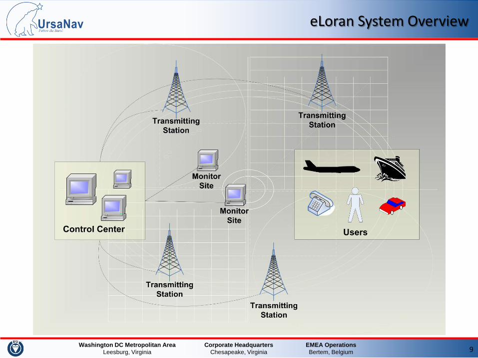
eLoran System Overview
EMEA Operations Bertem, Belgium
Corporate Headquarters Chesapeake, Virginia
Washington DC Metropolitan Area Leesburg, Virginia 10
eLoran System Overview (cont.)
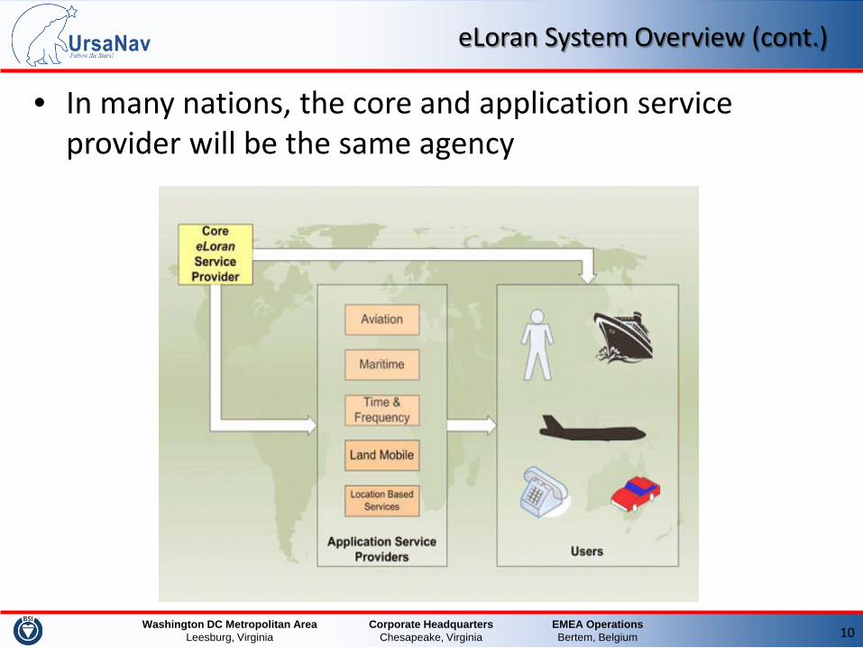
• In many nations, the core and application service provider will be the same agency
EMEA Operations Bertem, Belgium
Corporate Headquarters Chesapeake, Virginia
Washington DC Metropolitan Area Leesburg, Virginia 11
eLoran System Overview (cont.)
• Core eLoran service – eLoran transmitters provide a highly stable eLoran signal – eLoran transmitters are autonomous, unmanned, self-controlled, self-
supporting – Signals are synchronized to an identifiable source of UTC (no SAM control) – Monitor sites and Control centers do not interfere with the timing control
of the transmitted signal
• eLoran application service – To improve accuracy and/or integrity application specific monitor stations
provide augmentation data – Application data is broadcast to the users over the Loran Data Channel
(e.g. maritime differential corrections or aviation early skywave warnings) – Application data are treated as corrections or integrity warnings and will
not influence the delivery of the core eLoran service
EMEA Operations Bertem, Belgium
Corporate Headquarters Chesapeake, Virginia
Washington DC Metropolitan Area Leesburg, Virginia 12
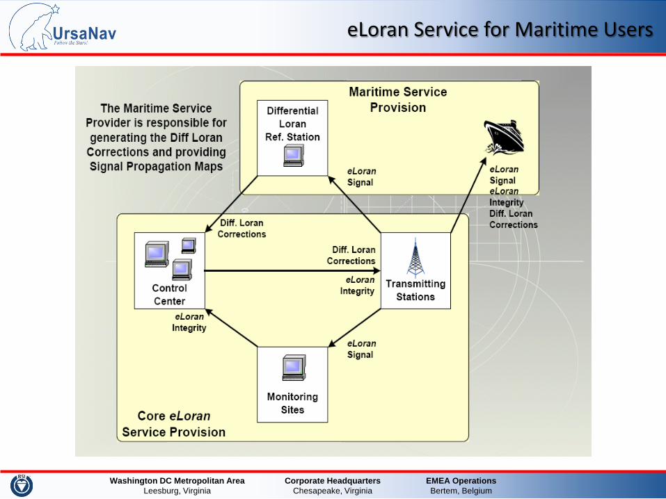
eLoran Maritime Application Service Provider
• The core eLoran service needs to provide signals with good geometry and signal strength in the maritime coverage area
• The Maritime Application service provider publishes an ASF map for the maritime coverage area, providing grid data with nominal propagation corrections per transmitter
• The Differential eLoran Reference Station provides real-time corrections on the nominal published ASFs for each transmitter through the Loran Data Channel
• The maritime user applies the ASFs from the map and differential corrections from the LDC to improve its positioning accuracy to better than 20 m (95%)
• The eLoran Integrity Monitor monitors the resulting eLoran accuracy and issues integrity warnings over the Loran Data Channel in case the service exceeds the horizontal protection limit
EMEA Operations Bertem, Belgium
Corporate Headquarters Chesapeake, Virginia
Washington DC Metropolitan Area Leesburg, Virginia 13
eLoran Signal in Space
• The eLoran Signal in Space for the most part follows the specified Loran-C signal as published by the USCG, differences include: – eLoran specifies tighter synchronization to UTC, tighter timing
tolerances between GRIs, between pulses and between zero-crossings in a pulse.
– eLoran specifies tighter tolerances with respect to pulse shape – Time and frequency equipment apply phase corrections in a
continuous manner instead of Local Phase Adjustments (LPA) of 10 or 20 ns steps.
– eLoran uses Time of Transmission (synchronization to UTC) for all stations instead of Service Area Monitoring (SAM) timing control.
– eLoran does not apply Blink anymore to indicate an out-of-tolerance condition. Integrity messages are conveyed through the LDC. In case of serious and harmful loss of synchronization, the transmitter will be take of the air.
EMEA Operations Bertem, Belgium
Corporate Headquarters Chesapeake, Virginia
Washington DC Metropolitan Area Leesburg, Virginia
100 kHz carrier
14
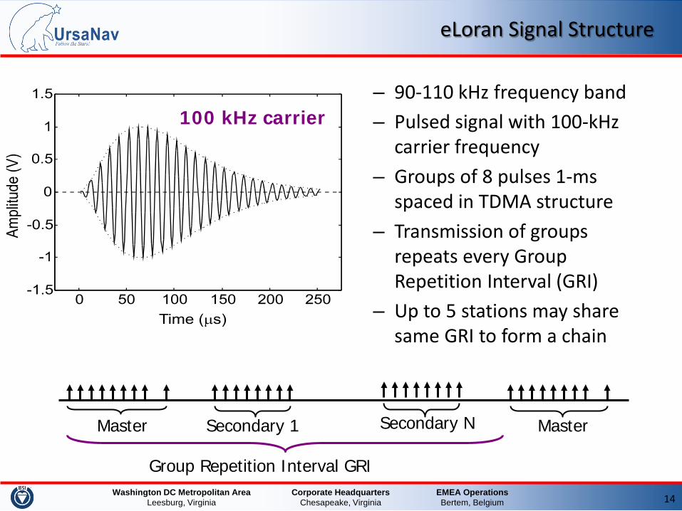
eLoran Signal Structure
– 90-110 kHz frequency band – Pulsed signal with 100-kHz
carrier frequency – Groups of 8 pulses 1-ms
spaced in TDMA structure – Transmission of groups
repeats every Group Repetition Interval (GRI)
– Up to 5 stations may share same GRI to form a chain
Group Repetition Interval GRI
Secondary 1 Master Secondary N Master
EMEA Operations Bertem, Belgium
Corporate Headquarters Chesapeake, Virginia
Washington DC Metropolitan Area Leesburg, Virginia 15
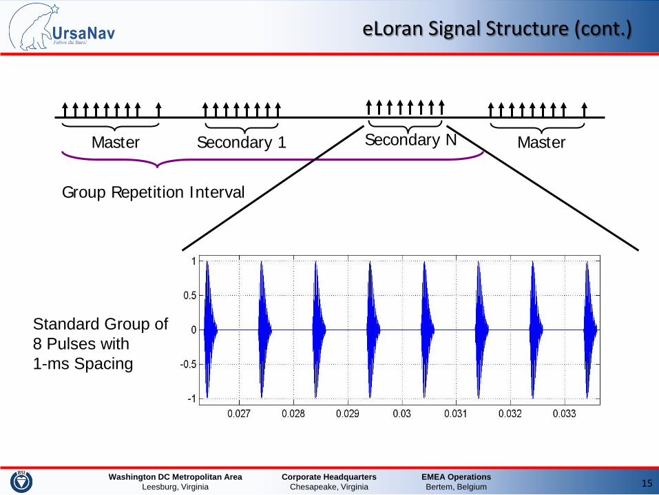
eLoran Signal Structure (cont.)
Standard Group of 8 Pulses with 1-ms Spacing
Group Repetition Interval
Secondary 1 Master Secondary N Master
EMEA Operations Bertem, Belgium
Corporate Headquarters Chesapeake, Virginia
Washington DC Metropolitan Area Leesburg, Virginia 16
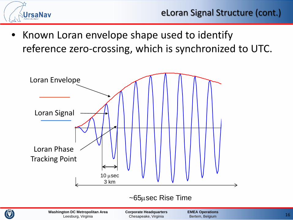
eLoran Signal Structure (cont.)
• Known Loran envelope shape used to identify reference zero-crossing, which is synchronized to UTC.
Loran Signal
Loran Envelope
10 µsec 3 km
Loran Phase Tracking Point
~65µsec Rise Time
EMEA Operations Bertem, Belgium
Corporate Headquarters Chesapeake, Virginia
Washington DC Metropolitan Area Leesburg, Virginia 17
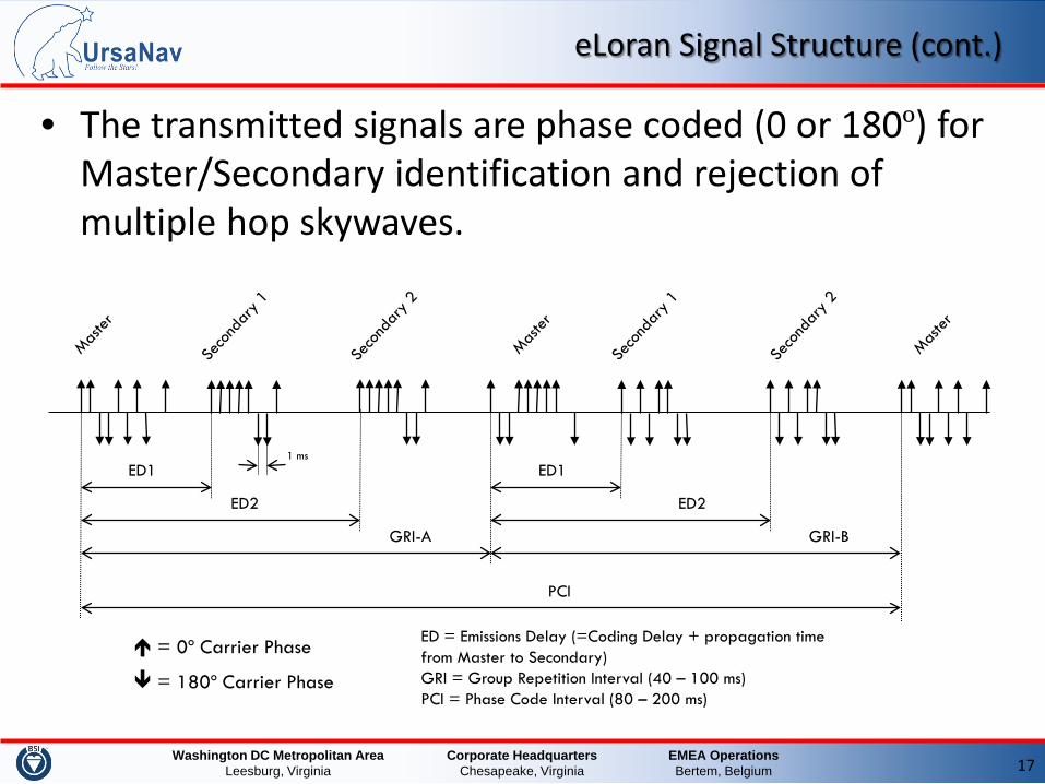
eLoran Signal Structure (cont.)
• The transmitted signals are phase coded (0 or 180º) for Master/Secondary identification and rejection of multiple hop skywaves.
ED = Emissions Delay (=Coding Delay + propagation time from Master to Secondary) GRI = Group Repetition Interval (40 – 100 ms) PCI = Phase Code Interval (80 – 200 ms)
= 0º Carrier Phase
= 180º Carrier Phase
1 ms ED1
ED2 ED2
ED1
GRI-A GRI-B
PCI
EMEA Operations Bertem, Belgium
Corporate Headquarters Chesapeake, Virginia
Washington DC Metropolitan Area Leesburg, Virginia 18
eLoran Signal Improvements
• Improved phase codes – Phase codes should average to zero. – Pseudo-Random Noise (PRN) based phase codes will allow
unique identification of a station in a group and will reduce cross-correlation of signals from other stations.
• The 9th Master pulse in the 10th pulse slot is no longer needed for identification and can be removed. This improves cross-rate interference and frees up the slot for the LDC.
• Waveforms can be improved over “standard” Loran-C. • Shorter pulses allow for more navigation pulses, or room for
more data. Navigation function is not degraded. • Shorter pulses reduce negative cross-rate and skywave
effects.
EMEA Operations Bertem, Belgium
Corporate Headquarters Chesapeake, Virginia
Washington DC Metropolitan Area Leesburg, Virginia 19
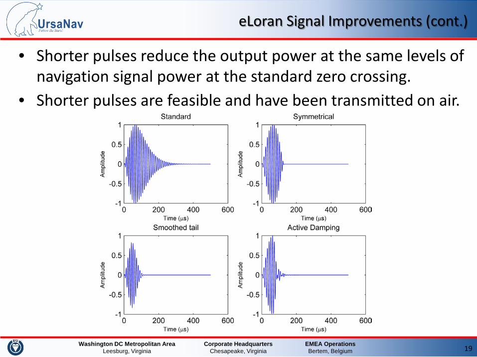
eLoran Signal Improvements (cont.)
• Shorter pulses reduce the output power at the same levels of navigation signal power at the standard zero crossing.
• Shorter pulses are feasible and have been transmitted on air.
EMEA Operations Bertem, Belgium
Corporate Headquarters Chesapeake, Virginia
Washington DC Metropolitan Area Leesburg, Virginia 20
eLoran Data Channel
• Major difference between Loran-C and eLoran is the Loran Data Channel
• Data Channel carries – Differential eLoran Correction – UTC Time of day and date information – eLoran Integrity information – Differential GPS information – GPS integrity information – Other data
• Two implementations exist: – 3-state Pulse Position Modulation (Eurofix)
• Standardised by RTCM and ITU – 9th Pulse Modulation
EMEA Operations Bertem, Belgium
Corporate Headquarters Chesapeake, Virginia
Washington DC Metropolitan Area Leesburg, Virginia 21
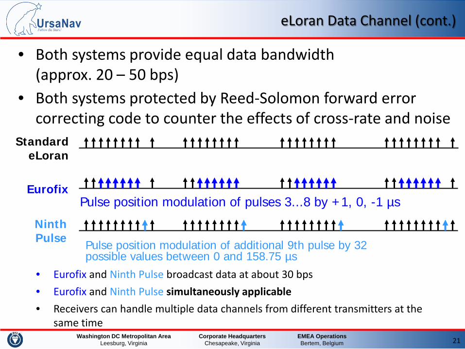
eLoran Data Channel (cont.)
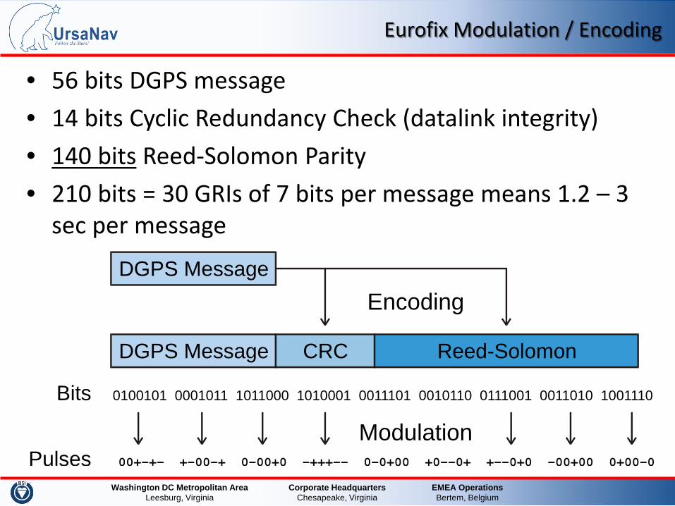
• Both systems provide equal data bandwidth (approx. 20 – 50 bps)
• Both systems protected by Reed-Solomon forward error correcting code to counter the effects of cross-rate and noise
• Eurofix and Ninth Pulse broadcast data at about 30 bps • Eurofix and Ninth Pulse simultaneously applicable • Receivers can handle multiple data channels from different transmitters at the
same time
Standard eLoran
Eurofix Pulse position modulation of pulses 3...8 by +1, 0, -1 µs
Ninth Pulse Pulse position modulation of additional 9th pulse by 32
possible values between 0 and 158.75 µs
EMEA Operations Bertem, Belgium
Corporate Headquarters Chesapeake, Virginia
Washington DC Metropolitan Area Leesburg, Virginia
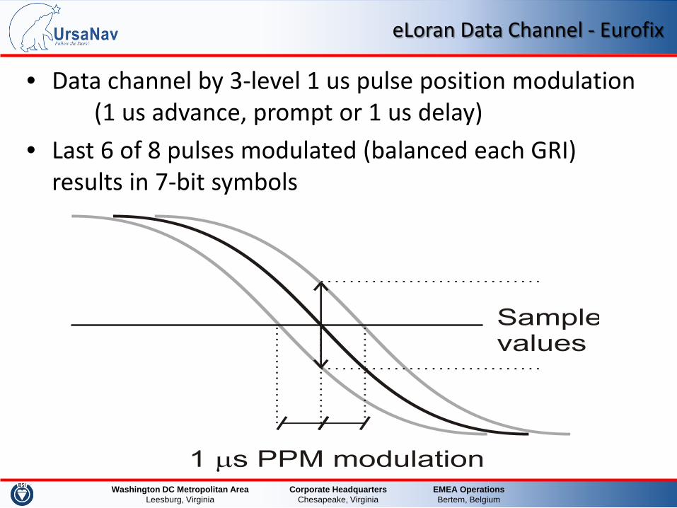
eLoran Data Channel - Eurofix
• Data channel by 3-level 1 us pulse position modulation (1 us advance, prompt or 1 us delay)
• Last 6 of 8 pulses modulated (balanced each GRI) results in 7-bit symbols
EMEA Operations Bertem, Belgium
Corporate Headquarters Chesapeake, Virginia
Washington DC Metropolitan Area Leesburg, Virginia
Washington DC Metropolitan Area Leesburg, Virginia
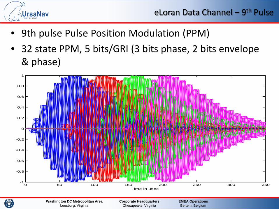
eLoran Data Channel – 9th Pulse
• 9th pulse Pulse Position Modulation (PPM) • 32 state PPM, 5 bits/GRI (3 bits phase, 2 bits envelope
& phase)
0 50 100 150 200 250 300 350-1
-0.8
-0.6
-0.4
-0.2
0
0.2
0.4
0.6
0.8
1
Time in usec
EMEA Operations Bertem, Belgium
Corporate Headquarters Chesapeake, Virginia
Washington DC Metropolitan Area Leesburg, Virginia
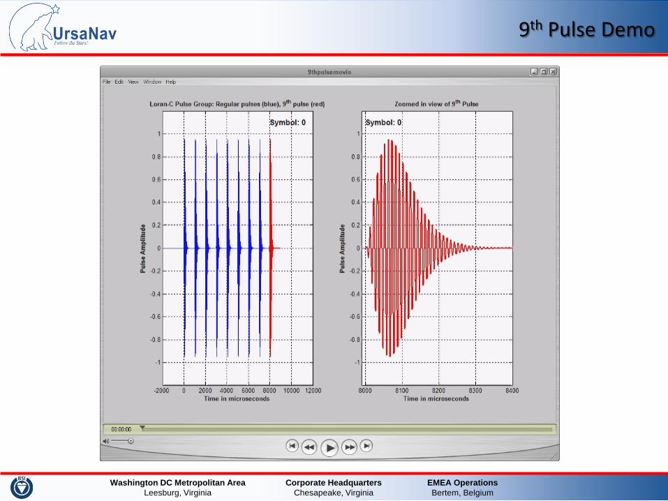
9th Pulse Demo
EMEA Operations Bertem, Belgium
Corporate Headquarters Chesapeake, Virginia
Washington DC Metropolitan Area Leesburg, Virginia
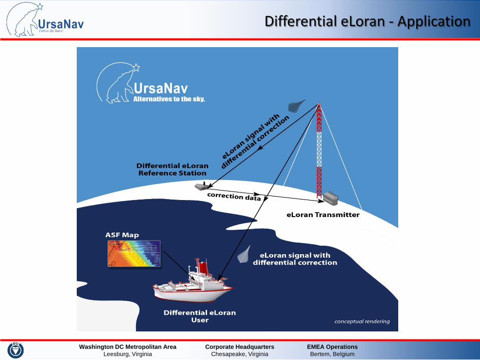
Differential eLoran - Application
EMEA Operations Bertem, Belgium
Corporate Headquarters Chesapeake, Virginia
Washington DC Metropolitan Area Leesburg, Virginia
eLoran Service for Maritime Users
EMEA Operations Bertem, Belgium
Corporate Headquarters Chesapeake, Virginia
Washington DC Metropolitan Area Leesburg, Virginia 28
eLoran for Maritime Uses
• To explain maritime ASF we need to understand: – Positioning using eLoran – eLoran signal propagation – Concept of ASFs and the ASF map – Concept of differential corrections
EMEA Operations Bertem, Belgium
Corporate Headquarters Chesapeake, Virginia
Washington DC Metropolitan Area Leesburg, Virginia 29
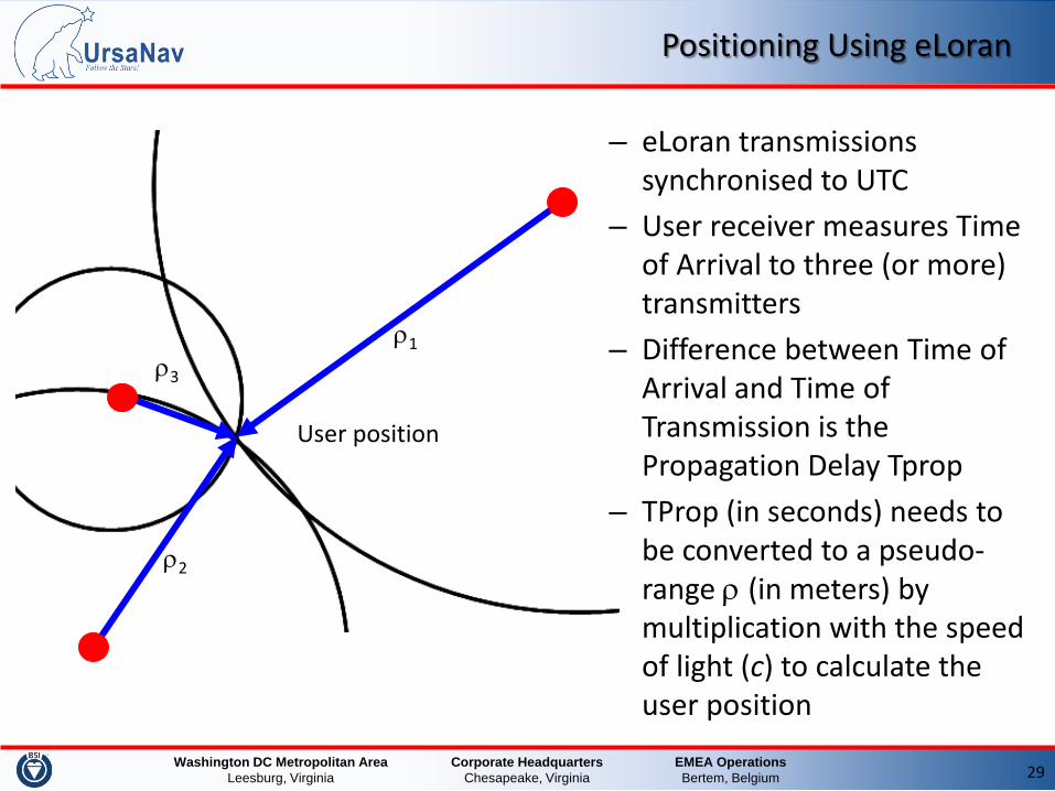
Positioning Using eLoran
– eLoran transmissions synchronised to UTC
– User receiver measures Time of Arrival to three (or more) transmitters
– Difference between Time of Arrival and Time of Transmission is the Propagation Delay Tprop
– TProp (in seconds) needs to be converted to a pseudo-range ρ (in meters) by multiplication with the speed of light (c) to calculate the user position
User position
ρ1
ρ2
ρ3
EMEA Operations Bertem, Belgium
Corporate Headquarters Chesapeake, Virginia
Washington DC Metropolitan Area Leesburg, Virginia 30
Positioning Using eLoran (cont.)
• A position calculation is based on 3 (or more) pseudoranges to 3 (or more) transmitters
• The receiver measures arrival times, which convert to pseudoranges by multiplication with the signals’ propagation velocity
• This velocity is not equal to the speed of light in vacuum, but depends on the medium the signals travel in and over!
EMEA Operations Bertem, Belgium
Corporate Headquarters Chesapeake, Virginia
Washington DC Metropolitan Area Leesburg, Virginia 31
eLoran Signal Propagation
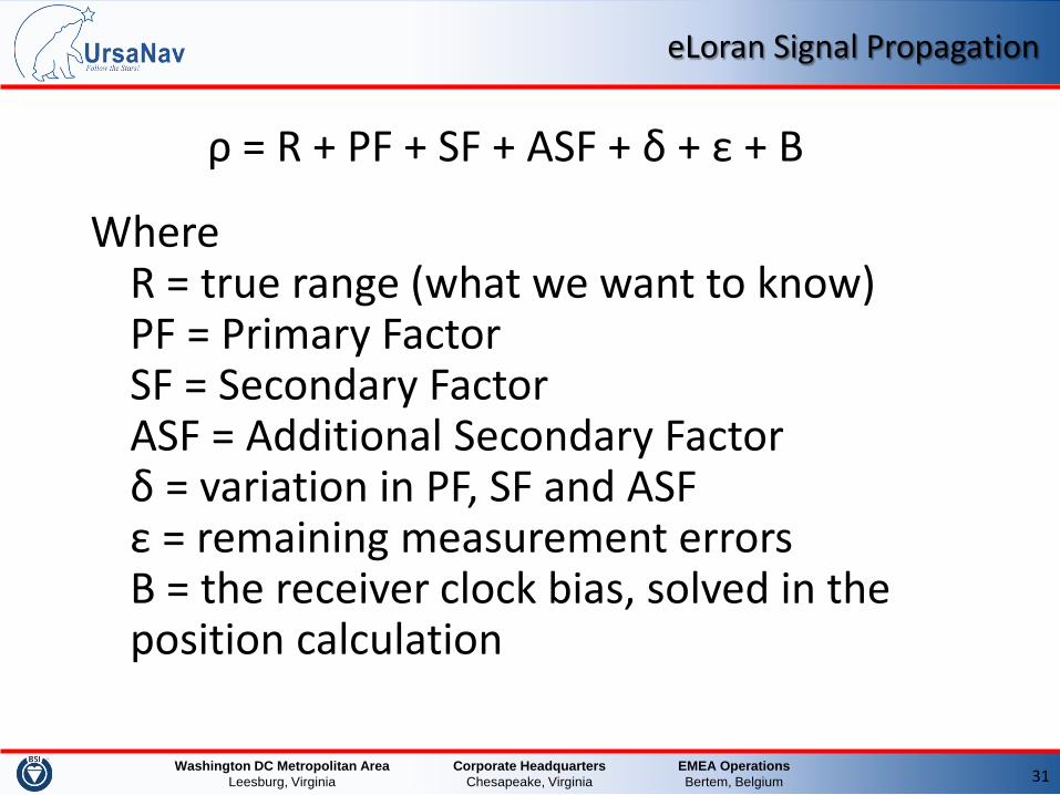
ρ = R + PF + SF + ASF + δ + ε + B
Where R = true range (what we want to know) PF = Primary Factor SF = Secondary Factor ASF = Additional Secondary Factor δ = variation in PF, SF and ASF ε = remaining measurement errors B = the receiver clock bias, solved in the position calculation
EMEA Operations Bertem, Belgium
Corporate Headquarters Chesapeake, Virginia
Washington DC Metropolitan Area Leesburg, Virginia 32
eLoran Signal Propagation (cont.)
EMEA Operations Bertem, Belgium
Corporate Headquarters Chesapeake, Virginia
Washington DC Metropolitan Area Leesburg, Virginia 33
Primary and Secondary Factor
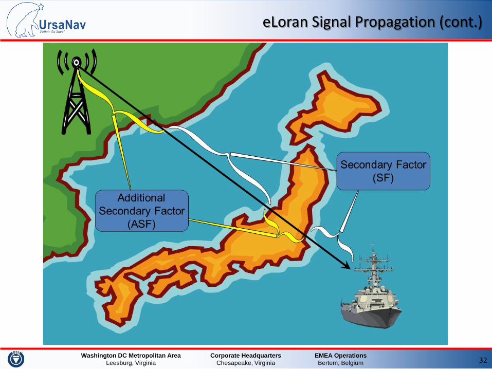
• The Primary Factor delay is the difference between propagation of the signal in the earth’s atmosphere as opposed to in free space
• The Secondary Factor delay accounts for signal propagation over sea-water
• PF and SF are known and considered constant, the receiver uses a model to calculate the delays
EMEA Operations Bertem, Belgium
Corporate Headquarters Chesapeake, Virginia
Washington DC Metropolitan Area Leesburg, Virginia 34
Additional Secondary Factor
• The Additional Secondary Factor is the delay caused by signal propagation over land and elevated terrain as opposed to over sea-water
• The ASF delay build-up depends on the type of soil • The ASF delay is the total cumulative delay the signal
experiences of sections with different ground conductivity
• The Maritime service provider publishes an ASF map for the operating area as a grid with surveyed nominal ASFs for each transmitter
• Not taking ASFs into account may result in positioning errors of several 100 meters to kilometers
EMEA Operations Bertem, Belgium
Corporate Headquarters Chesapeake, Virginia
Washington DC Metropolitan Area Leesburg, Virginia
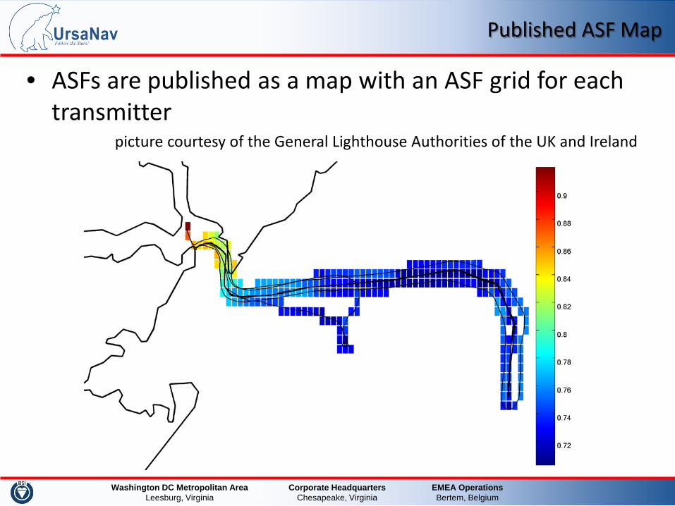
Published ASF Map
• ASFs are published as a map with an ASF grid for each transmitter
picture courtesy of the General Lighthouse Authorities of the UK and Ireland
EMEA Operations Bertem, Belgium
Corporate Headquarters Chesapeake, Virginia
Washington DC Metropolitan Area Leesburg, Virginia 36
Differential eLoran Corrections
• ASFs are relatively constant in time • Any variation in ASF due to weather, water vapor, air
pressure, seasonal influences is captured in δ • δ also contains any misalignment of the transmitter
timing wrt UTC • δ is unknown, but can be measured by a reference
station at a known and fixed location • In differential eLoran, these corrections are broadcast to
the users to improve their positioning and UTC time accuracy
EMEA Operations Bertem, Belgium
Corporate Headquarters Chesapeake, Virginia
Washington DC Metropolitan Area Leesburg, Virginia
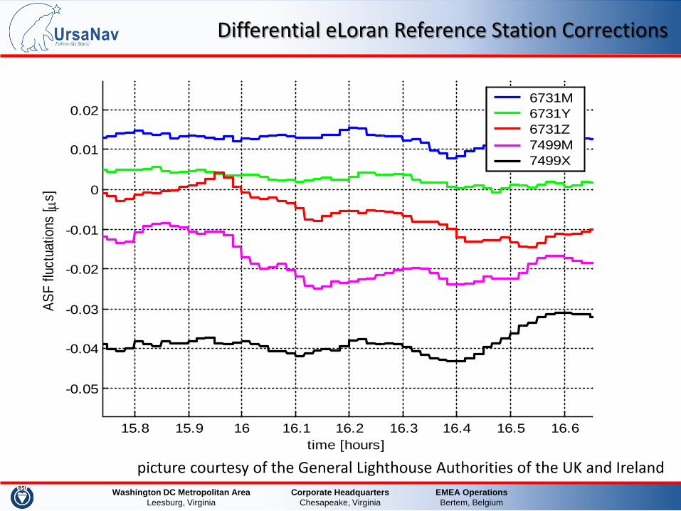
Differential eLoran Reference Station Corrections
picture courtesy of the General Lighthouse Authorities of the UK and Ireland
15.8 15.9 16 16.1 16.2 16.3 16.4 16.5 16.6
-0.05
-0.04
-0.03
-0.02
-0.01
0
0.01
0.02
time [hours]
ASF
fluct
uatio
ns [ µ
s]
6731M6731Y6731Z7499M7499X
EMEA Operations Bertem, Belgium
Corporate Headquarters Chesapeake, Virginia
Washington DC Metropolitan Area Leesburg, Virginia
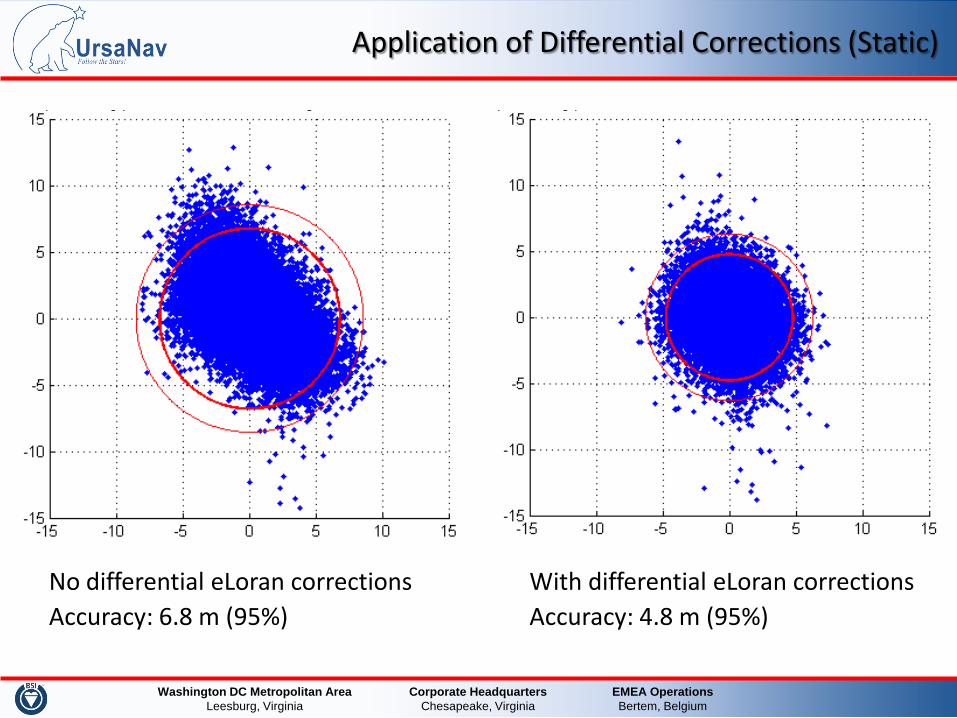
Application of Differential Corrections (Static)
No differential eLoran corrections Accuracy: 6.8 m (95%)
With differential eLoran corrections Accuracy: 4.8 m (95%)
EMEA Operations Bertem, Belgium
Corporate Headquarters Chesapeake, Virginia
Washington DC Metropolitan Area Leesburg, Virginia 39
Maritime Differential eLoran
• The Differential eLoran user calculates position based on: – eLoran range measurements – Corrected with modeled PF and SF – Corrected with ASF map values for the estimated location – Corrected with differential corrections coming from
eLoran Reference Station broadcast from eLoran transmitter
• Differential corrections compensate for changes in ASF map data and possible transmitter timing errors
EMEA Operations Bertem, Belgium
Corporate Headquarters Chesapeake, Virginia
Washington DC Metropolitan Area Leesburg, Virginia
Maritime Differential eLoran (cont.)
R + ε = (ρ - PF - SF - ASF - δ - B)
Where R = true range (what we want to know) PF = Primary Factor (modeled) SF = Secondary Factor (modeled) ASF = Additional Secondary Factor (published) δ = differential correction (broadcast) B = clock error bias (solved in positioning) ε = remaining measurement errors
Remaining errors ε, such as noise and interference cause the calculated position to deviate from the real position
EMEA Operations Bertem, Belgium
Corporate Headquarters Chesapeake, Virginia
Washington DC Metropolitan Area Leesburg, Virginia
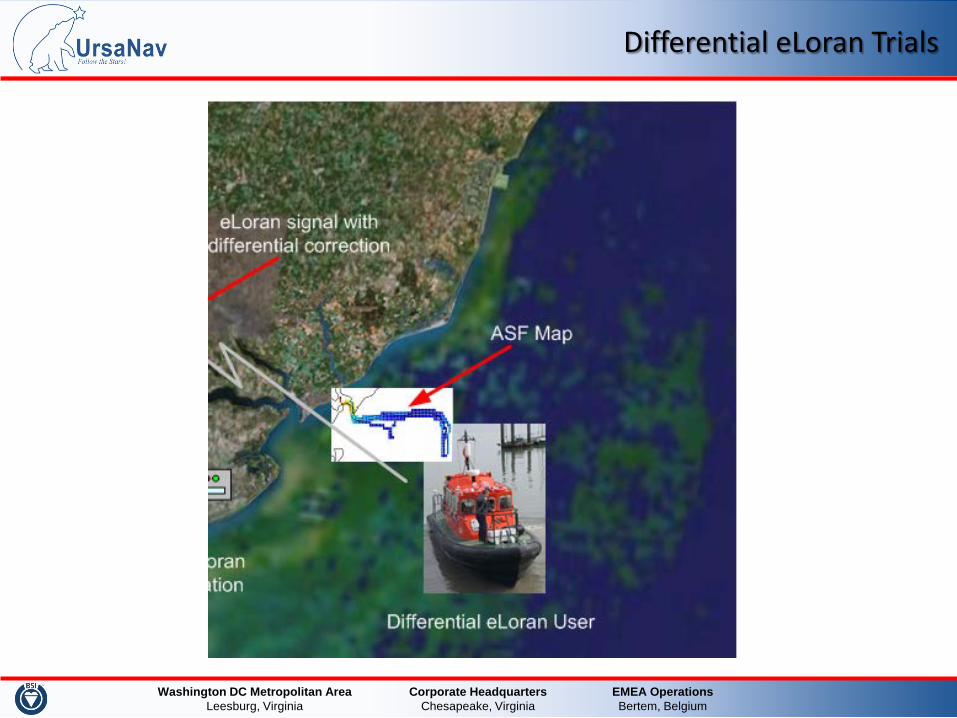
Differential eLoran Trials
EMEA Operations Bertem, Belgium
Corporate Headquarters Chesapeake, Virginia
Washington DC Metropolitan Area Leesburg, Virginia
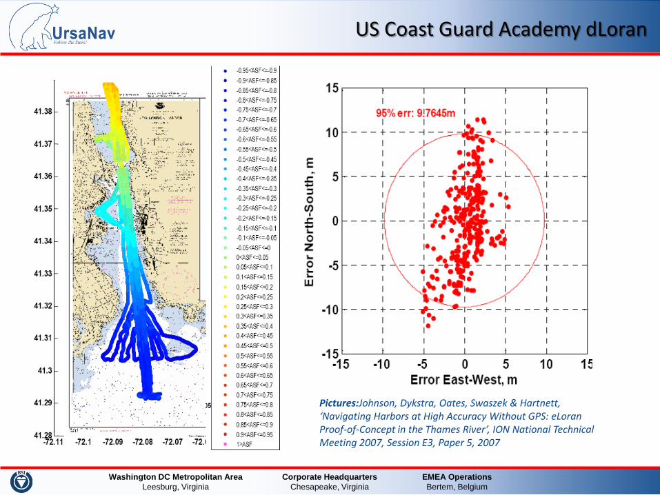
US Coast Guard Academy dLoran
Pictures:Johnson, Dykstra, Oates, Swaszek & Hartnett, ‘Navigating Harbors at High Accuracy Without GPS: eLoran Proof-of-Concept in the Thames River’, ION National Technical Meeting 2007, Session E3, Paper 5, 2007
EMEA Operations Bertem, Belgium
Corporate Headquarters Chesapeake, Virginia
Washington DC Metropolitan Area Leesburg, Virginia
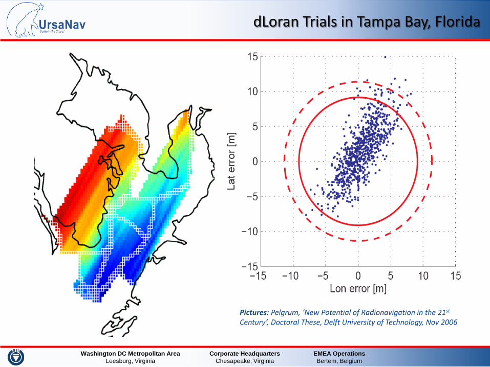
dLoran Trials in Tampa Bay, Florida
Pictures: Pelgrum, ‘New Potential of Radionavigation in the 21st Century’, Doctoral These, Delft University of Technology, Nov 2006
EMEA Operations Bertem, Belgium
Corporate Headquarters Chesapeake, Virginia
Washington DC Metropolitan Area Leesburg, Virginia
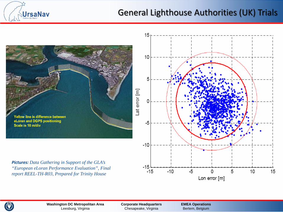
General Lighthouse Authorities (UK) Trials
Pictures: Data Gathering in Support of the GLA’s “European eLoran Performance Evaluation”, Final report REEL-TH-R03, Prepared for Trinity House
EMEA Operations Bertem, Belgium
Corporate Headquarters Chesapeake, Virginia
Washington DC Metropolitan Area Leesburg, Virginia 45
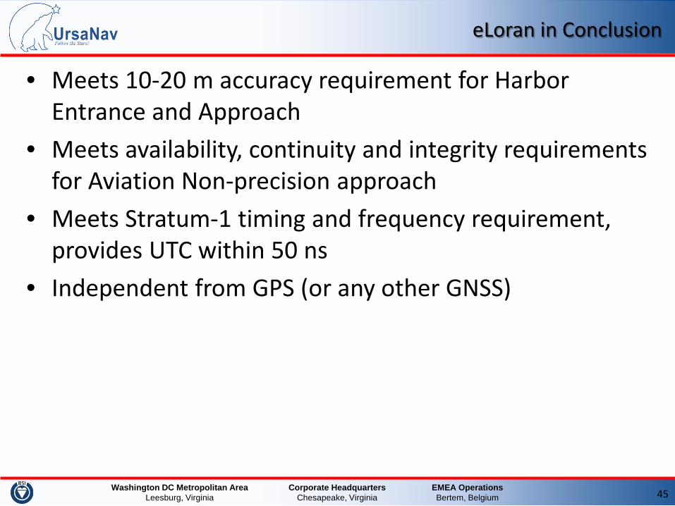
eLoran in Conclusion
• Meets 10-20 m accuracy requirement for Harbor Entrance and Approach
• Meets availability, continuity and integrity requirements for Aviation Non-precision approach
• Meets Stratum-1 timing and frequency requirement, provides UTC within 50 ns
• Independent from GPS (or any other GNSS)
EMEA Operations Bertem, Belgium
Corporate Headquarters Chesapeake, Virginia
Washington DC Metropolitan Area Leesburg, Virginia
Back-up Slides
EMEA Operations Bertem, Belgium
Corporate Headquarters Chesapeake, Virginia
Washington DC Metropolitan Area Leesburg, Virginia 47
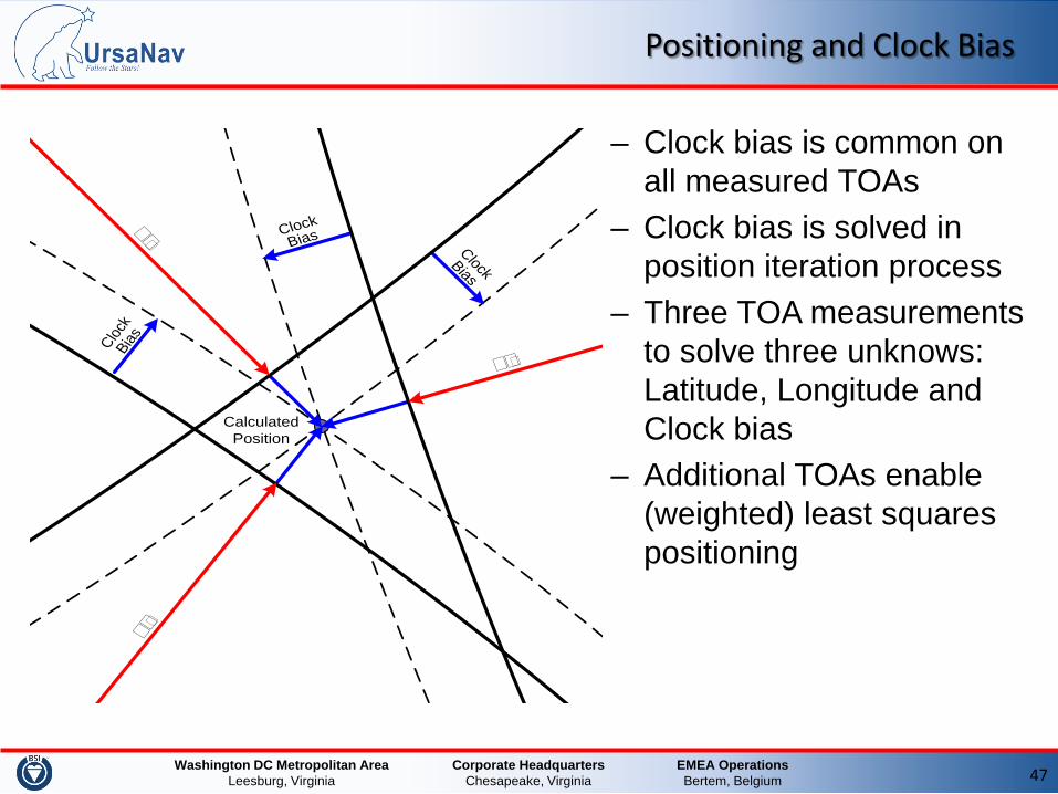
Positioning and Clock Bias
– Clock bias is common on all measured TOAs
– Clock bias is solved in position iteration process
– Three TOA measurements to solve three unknows: Latitude, Longitude and Clock bias
– Additional TOAs enable (weighted) least squares positioning


![Discrete Time Periodic Signals A discrete time signal x[n] is periodic with period N if and only if for all n. Definition: Meaning: a periodic signal keeps.](https://static.documents.pub/doc/80x56/56649d8c5503460f94a730c7/discrete-time-periodic-signals-a-discrete-time-signal-xn-is-periodic-with.jpg)


